EP3049766B1 - Vorrichtung und verfahren zum befestigen eines sensors und zum verschliessen eines schranks - Google Patents
Vorrichtung und verfahren zum befestigen eines sensors und zum verschliessen eines schranks Download PDFInfo
- Publication number
- EP3049766B1 EP3049766B1 EP14772342.3A EP14772342A EP3049766B1 EP 3049766 B1 EP3049766 B1 EP 3049766B1 EP 14772342 A EP14772342 A EP 14772342A EP 3049766 B1 EP3049766 B1 EP 3049766B1
- Authority
- EP
- European Patent Office
- Prior art keywords
- sensor
- bracket
- support rod
- housing
- external action
- Prior art date
- Legal status (The legal status is an assumption and is not a legal conclusion. Google has not performed a legal analysis and makes no representation as to the accuracy of the status listed.)
- Not-in-force
Links
Images


Classifications
-
- A—HUMAN NECESSITIES
- A47—FURNITURE; DOMESTIC ARTICLES OR APPLIANCES; COFFEE MILLS; SPICE MILLS; SUCTION CLEANERS IN GENERAL
- A47B—TABLES; DESKS; OFFICE FURNITURE; CABINETS; DRAWERS; GENERAL DETAILS OF FURNITURE
- A47B97/00—Furniture or accessories for furniture, not provided for in other groups of this subclass
-
- F—MECHANICAL ENGINEERING; LIGHTING; HEATING; WEAPONS; BLASTING
- F16—ENGINEERING ELEMENTS AND UNITS; GENERAL MEASURES FOR PRODUCING AND MAINTAINING EFFECTIVE FUNCTIONING OF MACHINES OR INSTALLATIONS; THERMAL INSULATION IN GENERAL
- F16M—FRAMES, CASINGS OR BEDS OF ENGINES, MACHINES OR APPARATUS, NOT SPECIFIC TO ENGINES, MACHINES OR APPARATUS PROVIDED FOR ELSEWHERE; STANDS; SUPPORTS
- F16M13/00—Other supports for positioning apparatus or articles; Means for steadying hand-held apparatus or articles
- F16M13/02—Other supports for positioning apparatus or articles; Means for steadying hand-held apparatus or articles for supporting on, or attaching to, an object, e.g. tree, gate, window-frame, cycle
-
- G—PHYSICS
- G01—MEASURING; TESTING
- G01D—MEASURING NOT SPECIALLY ADAPTED FOR A SPECIFIC VARIABLE; ARRANGEMENTS FOR MEASURING TWO OR MORE VARIABLES NOT COVERED IN A SINGLE OTHER SUBCLASS; TARIFF METERING APPARATUS; MEASURING OR TESTING NOT OTHERWISE PROVIDED FOR
- G01D11/00—Component parts of measuring arrangements not specially adapted for a specific variable
- G01D11/24—Housings ; Casings for instruments
- G01D11/245—Housings for sensors
-
- G—PHYSICS
- G01—MEASURING; TESTING
- G01D—MEASURING NOT SPECIALLY ADAPTED FOR A SPECIFIC VARIABLE; ARRANGEMENTS FOR MEASURING TWO OR MORE VARIABLES NOT COVERED IN A SINGLE OTHER SUBCLASS; TARIFF METERING APPARATUS; MEASURING OR TESTING NOT OTHERWISE PROVIDED FOR
- G01D11/00—Component parts of measuring arrangements not specially adapted for a specific variable
- G01D11/30—Supports specially adapted for an instrument; Supports specially adapted for a set of instruments
-
- A—HUMAN NECESSITIES
- A47—FURNITURE; DOMESTIC ARTICLES OR APPLIANCES; COFFEE MILLS; SPICE MILLS; SUCTION CLEANERS IN GENERAL
- A47B—TABLES; DESKS; OFFICE FURNITURE; CABINETS; DRAWERS; GENERAL DETAILS OF FURNITURE
- A47B2220/00—General furniture construction, e.g. fittings
- A47B2220/0091—Electronic or electric devices
-
- F—MECHANICAL ENGINEERING; LIGHTING; HEATING; WEAPONS; BLASTING
- F25—REFRIGERATION OR COOLING; COMBINED HEATING AND REFRIGERATION SYSTEMS; HEAT PUMP SYSTEMS; MANUFACTURE OR STORAGE OF ICE; LIQUEFACTION SOLIDIFICATION OF GASES
- F25D—REFRIGERATORS; COLD ROOMS; ICE-BOXES; COOLING OR FREEZING APPARATUS NOT OTHERWISE PROVIDED FOR
- F25D2700/00—Means for sensing or measuring; Sensors therefor
- F25D2700/02—Sensors detecting door opening
-
- F—MECHANICAL ENGINEERING; LIGHTING; HEATING; WEAPONS; BLASTING
- F25—REFRIGERATION OR COOLING; COMBINED HEATING AND REFRIGERATION SYSTEMS; HEAT PUMP SYSTEMS; MANUFACTURE OR STORAGE OF ICE; LIQUEFACTION SOLIDIFICATION OF GASES
- F25D—REFRIGERATORS; COLD ROOMS; ICE-BOXES; COOLING OR FREEZING APPARATUS NOT OTHERWISE PROVIDED FOR
- F25D29/00—Arrangement or mounting of control or safety devices
- F25D29/005—Mounting of control devices
Definitions
- the present invention relates to a device for mounting a sensor and for sealing a cabinet.
- a contact sensor is often rigidly fixed on a stationary frame, and the contact sensor is not movable relative to the stationary frame.
- the contact sensor must be mounted in a high position accuracy to ensure an external action displacement applied on a sensing contact of the sensor within a maximum stroke (a safe stroke) of the sensing contact.
- the contact sensor must have an enough mechanical strength to bear an overlarge external action force applied on the sensor by a triggering action (for example, a contact triggering action or a close triggering action).
- an overlarge external action force may cause the internal structure of the sensor to collapse and fail. Further, if the sensor is mounted in poor position accuracy, the external action displacement applied on a sensing contact of the sensor may be beyond the maximum stroke of the sensing contact, and the sensor may be ruined.
- Providing an indication that the sensor is sensing a correct condition, such as a door being closed, or a door sealing against a seal is also a concern.
- the present invention has been made to overcome or alleviate at least one aspect of the above mentioned disadvantages and concerns.
- the present invention is defined by independent claim 1.
- the elastic element is configured that:
- an opening is formed in the bracket; and at least a portion of the housing of the sensor is received in the opening and movable in the opening.
- the device comprises a plurality of support rods, and the plurality of support rods pass through respective mounting holes in the housing and respective guide holes in the bracket.
- the support rod has a first end and a second end opposite to the first end; and the first end of the support rod is positioned at one of the sensor and the bracket, and the second end of the support rod is positioned at the other of the sensor and the bracket.
- a radial slot is formed in the first end of the support rod, and a stop piece is provided in the radial slot to position the first end of the support rod at one of the sensor and the bracket; and a radial protrusion portion is formed on the second end of the support rod to position the second end of the support rod at the other of the sensor and the bracket.
- the opening is opened at a side edge of the bracket and has a substantially U-shape.
- two elastic elements are disposed at both sides of the support rod relative to the bracket, respectively.
- one elastic element is disposed at only one side of the support rod relative to the bracket.
- the bracket comprises: a first portion on which the sensor is mounted; and a second portion perpendicular to the first portion and fixed to a stationary body.
- the bracket is formed by folding a strip of plate material; and the first portion is configured to be a rectangle frame formed by folding the strip of plate material.
- the bracket comprises: a first wall on which the sensor is mounted; a second wall perpendicular to the first wall and fixed to a stationary body; and a third wall connected between the first and second walls, so that the bracket exists a triangle shape.
- the bracket is made by molding or machining.
- the senor is configured to be a contact sensor.
- the senor is configured to be a micro electromechanical sensor or a fiber optic sensor.
- the sensor when an overlarge external action force beyond the initial deformation force (that is, a protection force for the sensor) F0 or an overlarge external action displacement beyond the maximum stroke of the sensing contact is applied on the sensor, the sensor is moved relative to the bracket along the support rod against the elastic element. Since the elastic element can provide an elastic buffer distance for the sensor, it reduces the request for the initial mounting position accuracy of the sensor, and ensures that the sensor can still work normally under the overlarge external action force or the overlarge external action displacement.
- the senor is configured to be a contact sensor to sense when a door of a cabinet is properly closed and a seal is properly engaged.
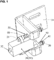
- Fig.1 is an illustrative perspective view of a device for mounting a sensor 30 according to an exemplary embodiment of the present invention
- Fig.2 is an illustrative perspective view of a bracket 10 of the device of Fig.1
- Fig.3 is an illustrative perspective view of a support rod 20 of the device of Fig.1 .
- a device for mounting a sensor 30, comprising: a bracket 10 formed with at least one guide hole 13 therein; at least one support rod 20 each passing through a mounting hole in a housing 31 of the sensor 30 and the guide hole 13 in the bracket 10 and mounted on the housing 31 of the sensor 30 and the bracket 10; and at least one elastic element 50 each disposed on the support rod 20, so that the sensor 30 is movable relative to the bracket 10 along the support rod 20 against the elastic element 50.
- the bracket 10 mainly comprises a first portion 11 and a second portion 12.
- the sensor 30 is mounted on the first portion 11.
- the second portion 12 is perpendicular to the first portion 11 and fixed to a stationary body (not shown).
- a plurality of elongated through holes 15 are formed in the second portion 12. Fasteners, for example, screws or bolts, may be inserted through the holes 15 and secured to the stationary body.
- the bracket 10 is formed by folding, cutting, and punching a strip of plate, and the first portion 11 is configured to be a rectangle frame formed by folding the strip of plate.
- an opening 14 is formed in the bracket 10.
- the opening 14 is opened at a side edge of the bracket 10 and has a substantially U-shape.
- the sensor 30 can be easily mounted in the opening 14.
- at least a portion of the housing 31 of the sensor 30 is received in the opening 14 and movable in the opening 14.
- the device comprises a pair of support rods 20.
- One of the support rods 20 passes through an upper mounting hole in the housing 31 and an upper guide hole 13 in the bracket 10 above the opening 14, and the other of the support rods 20 passes through a lower mounting hole in the housing 31 and a lower guide hole 13 in the bracket 10 below the opening 14.
- the device may comprise one, three or more support rod(s) 20.
- the support rod 20 has a first end (right end in Fig.3 ) and a second end (left end in Fig.3 ) opposite to the first end.
- the first end of the support rod 20 passes through the mounting hole in a housing 31 of the sensor 30 and the guide hole 13 in the bracket 10.
- a radial ring slot 22 is formed in the first end of the support rod 20, and a stop piece 40 is provided in the radial ring slot 22 to position the first end of the support rod 20 at the bracket 10.
- a radial protrusion portion 21 is formed on the second end of the support rod 20 to position the second end of the support rod 20 on the housing 31 of the sensor 30.
- the support rod 20 can be mounted on the housing 31 of the sensor 30 and the bracket 10 by the stop piece 40 at the first end and the radial protrusion portion 21 at the second end, respectively. Further, the support rod 20 cannot be disengaged from the housing 31 of the sensor 30 and the bracket 10 under the limit of the stop piece 40 and the radial protrusion portion 21.
- the first end of the support rod 20 having the radial slot 22 may be positioned on the housing 31 of the sensor 30, and the second end of the support rod 20 having the radial protrusion portion 21 may be positioned at the bracket 10.
- first end and the second end of the support rod 20 each may be formed with the radial slot 22, and the first end and the second end of the support rod 20 may be positioned at the bracket 10 and the sensor 30, respectively, by inserting the stop pieces 40 into the radial slots 22.
- two elastic elements 50 are disposed at both sides of the support rod 20 relative to the bracket 10.
- the elastic element 50 may be a spring or other suitable elastic piece.
- a first elastic element 50 is mounted on the support rod 20 with one end elastically engaged to (or contact) the stop piece 40 and the other end elastically engaged to (or contact) the bracket 10.
- a second elastic element 50 is mounted on the support rod 20 with one end being elastically engaged to (or contact) a washer 60 (sleeved on the support rod 20 and abutted against the housing 31 of the sensor 30, for example, an elastic washer) and the other end elastically engaged to (or contact) the bracket 10.
- the washer 60 is not necessary in the present invention, the washer 60 may be eliminated, and the second elastic element 50 may be directly and elastically engaged to (or contact) the housing 31 of the sensor 30.
- the senor 30 is configured to be a contact sensor.
- the sensor 30 may be configured to be a micro electromechanical sensor or a fiber optic sensor.
- the elastic element 50 is configured that:
- the forces Fa, Fl', F0, Fmax each is a constant, and the external action force F1 is a variable and can be gradually increased from zero.
- the sensor is trigged and sends the signal.
- the sensing contact 32 is moved to the position flush with the housing 31, at this time, the sensing contact 32 reaches the maximum stroke thereof.
- the sensing contact 32 and the housing 31 are not moved and are kept in a stationary state.
- the housing 31 of the sensor 30 begins to be moved against the elastic element 50.
- the elastic element 50 is compressed or stretched during mounting the sensor 30 to generate the initial deformation force F0.
- the initial deformation force F0 is served as the protection force for the sensor 30 and may be adjusted as necessary.
- the initial deformation force F0 of the elastic element 50 may be adjusted by changing the initial compressed or stretched amount, the material, or the size of the elastic element 50.
- an adjusting means for adjusting the initial compressed or stretched amount of the elastic element 50 may be provided on the support rod 20.
- the adjusting means may comprise a nut screwed on the support rod 20.
- the initial compressed or stretched amount of the elastic element 50 can be changed by screwing the nut on the support rod 20.
- the adjusting means may comprise a plurality of radial slots 22 formed at different axial positions of the support rod 20.
- the initial compressed or stretched amount of the elastic element 50 may be changed by inserting the stop piece into different radial slots 22.
- the initial deformation force F0 of the elastic element 50 may be changed by adjusting the length of the elastic element 50, the elasticity coefficient of the elastic element 50, the thickness of the stop piece 40 or the washer 60.
- the sensing contact 32 extends out of the housing 31 of the sensor 30 and can be moved by a safe stroke (the maximum stroke) relative to the housing 31.
- a safe stroke the maximum stroke
- the external action force is directly exerted on the housing 31 of the sensor 30. Since the housing 31 is moveably mounted on the support rod 20, the housing 31 can be moved by a distance (this distance can be adjusted by changing the number of the coils of the elastic element 50 and the position of the radial slot 22 on the support rod 20) relative to the bracket 10 along the support rod 20 against the deformation force of the elastic element 50 when the overlarge external action force is exerted on the housing 31.
- the external action displacement is within the safe stroke of the sensing contact 32 if the sensor 30 is accurately mounted in position.
- the sensor 30 is mounted in poor position accuracy, the external action displacement may exceed the safe stroke of the sensing contact 32.
- the sensor since the sensor is rigidly fixed to a stationary frame and cannot be moved, the sensor may be ruined when the external action displacement exceeds the safe stroke of the sensing contact. Therefore, in the prior art, the sensor must be mounted in high position accuracy to prevent the external action displacement from exceeding the safe stroke of the sensing contact.
- the support rod(s) and the elastic element(s) function as a bumper which can absorb the external action displacement exceeding the safe stroke of the sensing contact. Even if the sensor 30 is mounted in poor position accuracy and the external action displacement exceeds the safe stroke of the sensing contact 32, the sensor 30 can still work normally. Accordingly, the present invention reduces the request for the initial mounting position accuracy of the sensor 30.
- Fig.4 is an illustrative perspective view of a device for mounting a sensor 30 according to another exemplary embodiment of the present invention.
- an elastic element 50 is disposed at only one side of the support rod 20 proximal to the sensor 30, and there is not disposed the elastic element 50 at the other side of the support rod 20 distal to the sensor 30.
- the elastic element 50 may be disposed at only one side of the support rod 20 distal to the sensor 30, and there is not disposed the elastic element 50 at the other side of the support rod 20 proximal to the sensor 30.
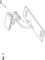
- the bracket 100 mainly comprises: a first wall 110 on which the sensor 30 is mounted; a second wall 120 perpendicular to the first wall 110 and fixed to a stationary body; and a third wall 130 connected between the first and second walls 110, 120, so that the bracket 100 exists a triangle shape.
- an opening 114 is formed in the first wall 110. At least a portion of the housing 31 of the sensor 30 is received in the opening 114 and movable in the opening 114.
- a plurality of elongated through holes 115 are formed in the second wall 120. Fasteners, for example, screws or bolts, may be inserted through the holes 115 and secured to a stationary body (not shown).
- the bracket 100 may be made by molding or machining.
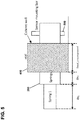
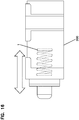
- the sensor 200 is mounted with a spring 1, that has to move over a distance ⁇ x1 to be activated to send a signal.
- the sensor is mounted on two additional springs 2 that are fixed in the cabinet.
- the door edge 300 needs to just touch the seal 400.
- the springs 2 will then have moved over a distance ⁇ x2. Once the door touches the seal, the seal may be further compressed against cabinet body 450 during closing. When the seal is fully compressed by the door the sensor has to be activated.
- the minimum outward position of the top of the sensor (out of the cabinet wall) may be: ⁇ x1 + ⁇ x2 + Dseal_compressed (see Fig. 6 minimum outward position of the sensor).
- the positioning of the sensor will be between the extremes. This creates some tolerance for possible deformations of the cabinet during transport or mounting.
- the preloading of springs 2 there may be a small preloading of the springs 2.
- this preloading in one implementation is not so large that springs 2 do not move before spring 1 is bottomed out.
- the preloading of springs 2 can indeed be so large that first spring 1 bottoms out before springs 2 move. It is also possible to have no preloading. In that case the total movement will be larger.
- the purpose of the design is that the sensor indicates that sealing is achieved. If the door is not closed completely, the springs will push the door open again. The installer or technician will notice this and the sensor will be deactivated. The sensor also indicates closure of the door at the end of the installation or intervention in the cabinet.
- spring 1 would move and later springs 2 would move, once the force on spring 1 reaches the preloading force on springs 2.
- Spring 1 moves to a sensing and signaling position, and then springs 2 moves, when the force in spring 1 reaches the preloading force in springs 2.
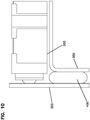
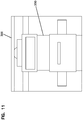
- Bracket 500 holds sensor 200 in position so that sensor 200 will signal when door 300 is properly closed and sealed against seal 400.
- seal 400 is positioned between cabinet body 450 and door 300, which in the example is hinged to cabinet body 450.
- Sensor 200 senses when the door is closed and the seal is compressed as in Figs. 10 and 11 .
- Brackets 500, 500a, 500b, 500c are adjustably mounted with fasteners and slots to cabinet body 450 at or between the maximum position of Fig. 5 and the minimum position of Fig. 6 .
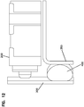
- Figs. 12-15 show an improperly closed and unsealed condition.
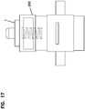
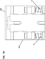
- Figs. 16-19 show the spring loaded sensor 200 and the mounting springs 2, which together allow for the desired sensing of the sealed condition of the cabinet.
- bracket 500 is adjusted so that sensor 200 sends a proper signal when the door is both closed and sealed. Once installed, the sensor 200 will activate and send a closed and sealed signal to the technician each time the door is properly closed and sealed.
Landscapes
- Physics & Mathematics (AREA)
- General Physics & Mathematics (AREA)
- Engineering & Computer Science (AREA)
- General Engineering & Computer Science (AREA)
- Mechanical Engineering (AREA)
- Force Measurement Appropriate To Specific Purposes (AREA)
- Casings For Electric Apparatus (AREA)
Claims (15)
- Ein System, beinhaltend:einen Sensor (30, 200) undeine Vorrichtung zum Befestigen des Sensors, beinhaltend:eine den Sensor (30, 200) haltende Klammer (10, 100, 500, 500a, 500b, 500c), wobei die Klammer verstellbar an einem Schrankkörper (450) befestigbar ist, wobei die Klammer mit mindestens einem Führungsloch (13) darin gebildet ist;mindestens eine Stützstange (20), die jeweils durch ein Befestigungsloch in einem Gehäuse (31) des Sensors (30, 200) und das Führungsloch (13) in der Klammer (10, 100, 500, 500a, 500b, 500c) führen und von dem Gehäuse (31) des Sensors (30, 200) und der Klammer (10, 100, 500, 500a, 500b, 500c) gestützt werden; undmindestens ein elastisches Element (50), die jeweils auf der Stützstange (20) angeordnet sind, sodass der Sensor (30, 200) relativ zu der Klammer (10, 100, 500, 500a, 500b, 500c) entlang der Stützstange (20) gegen das elastische Element (50) bewegbar ist,wobei der Sensor (30, 200) einen Erfassungskontakt (32) umfasst, der sich von dem Gehäuse (31) des Sensors (30, 200) erstreckt und konfiguriert ist, um eine bewegbare Tür (300) zu berühren, wobei der Erfassungskontakt (32) relativ zu dem Gehäuse (31) des Sensors (30, 200) bewegbar ist, wenn die bewegbare Tür (300) den Erfassungskontakt (32) berührt.
- System gemäß Anspruch 1, wobei das elastische Element (50) so konfiguriert ist, dass:(i) das elastische Element (50) eine anfängliche Verformungskraft F0 auf den Sensor (30, 200) ausübt, wenn keine externe Aktionskraft F1 auf den Sensor (30, 200) ausgeübt wird, wobei die anfängliche Verformungskraft F0 eingestellt ist, um geringfügig größer als eine erste externe Aktionskraft F1' zu sein, unter der ein Erfassungskontakt (32) des Sensors (30, 200) in eine mit dem Gehäuse (31) bündige Position bewegt wird, und kleiner als eine maximale externe Aktionskraft Fmax zu sein, die auf den Sensor (30, 200) ausgeübt werden darf; und(ii) die anfängliche Verformungskraft F0 auf den Sensor (30, 200) in einer Richtung ausgeübt wird, die entgegengesetzt einer Richtung ist, in der die externe Aktionskraft F1 auf den Sensor (30, 200) ausgeübt wird, wobei, wenn die auf den Sensor (30, 200) ausgeübte externe Aktionskraft F1 kleiner als oder gleich der anfänglichen Verformungskraft F0 ist, das Gehäuse (31) des Sensors (30, 200) nicht bewegt wird und das elastische Element (50) durch das Gehäuse (31) nicht bewegt und verformt wird; undwobei, wenn die auf den Sensor (30, 200) ausgeübte externe Aktionskraft F1 erhöht wird, um größer als die anfängliche Verformungskraft F0 zu sein, das Gehäuse (31) des Sensors (30, 200) anfängt, gegen das elastische Element (50) bewegt zu werden, und ein Teil der externen Aktionskraft F1 über der anfänglichen Verformungskraft F0 in eine Verformungskraft des elastischen Elements (50) umgewandelt wird, um sicherzustellen, dass der Sensor (30, 200) unter einer übergroßen externen Aktionskraft oder einer übergroßen externen Aktionsversetzung normal arbeitet.
- System gemäß Anspruch 2, wobei in der Klammer (10, 100, 500, 500a, 500b, 500c) eine Öffnung (14, 114) gebildet ist; und
wobei mindestens ein Teil des Gehäuses (31) des Sensors (30, 200) in der Öffnung (14) aufgenommen wird und in der Öffnung (14) bewegbar ist. - System gemäß Anspruch 3, wobei die Vorrichtung eine Vielzahl von Stützstangen (20) beinhaltet und die Vielzahl von Stützstangen (20) durch entsprechende Befestigungslöcher in dem Gehäuse (31) und entsprechende Führungslöcher (13) in der Klammer (10, 100, 500, 500a, 500b, 500c) führt.
- System gemäß Anspruch 4, wobei die Stützstange (20) ein erstes Ende und ein dem ersten Ende gegenüberliegendes zweites Ende aufweist; und
wobei das erste Ende der Stützstange (20) an einem von dem Sensor (30, 200) und der Klammer (10, 100, 500, 500a, 500b, 500c) positioniert ist und das zweite Ende der Stützstange (20) an dem anderen von dem Sensor (30, 200) und der Klammer (10) positioniert ist. - System gemäß Anspruch 5, wobei in dem ersten Ende der Stützstange (20) eine radiale Aussparung (22) gebildet ist und in der radialen Aussparung (22) ein Stoppstück (40) bereitgestellt ist, um das erste Ende der Stützstange (20) an einem von dem Sensor (30, 200) und der Klammer (10, 100, 500, 500a, 500b, 500c) zu positionieren; und
wobei auf dem zweiten Ende der Stützstange (20) ein radialer Vorsprungsteil (21) gebildet ist, um das zweite Ende der Stützstange (20) an dem anderen von dem Sensor (30, 200) und der Klammer (10, 100, 500, 500a, 500b, 500c) zu positionieren. - System gemäß Anspruch 6, wobei zwei elastische Elemente (50) an beiden Seiten der Stützstange (20) jeweils relativ zu der Klammer (10, 100, 500, 500a, 500b, 500c) angeordnet sind.
- System gemäß Anspruch 7, wobei die Klammer (10, 100, 500, 500a, 500b, 500c) Folgendes beinhaltet:einen ersten Teil (11, 110), an dem der Sensor (30, 200) befestigt ist; undeinen zweiten Teil (12, 120), der zu dem ersten Teil (11, 110) senkrecht ist und an einem stationären Körper fixiert ist.
- System gemäß Anspruch 8, wobei die Klammer (10, 100, 500, 500a, 500b, 500c) Folgendes beinhaltet:
eine dritte Wand (130), die zwischen dem ersten und zweiten Teil (110, 120) angeschlossen ist, sodass die Klammer (10, 100, 500, 500a, 500b, 500c) eine Dreiecksform aufweist. - System gemäß Anspruch 1, wobei der Sensor (30, 200) konfiguriert ist, um ein Kontaktsensor zu sein.
- System gemäß Anspruch 1, wobei der Sensor (30, 200) konfiguriert ist, um ein mikroelektromechanischer Sensor oder ein faseroptischer Sensor zu sein.
- Ein Schrank, beinhaltend:einen Schrankkörper (450);eine bewegbare Tür (300);eine Abdichtung (400) zwischen der Tür und dem Schrankkörper;das System gemäß einem der vorhergehenden Ansprüche, wobei der Sensor konfiguriert ist, um zu erfassen, wenn die Tür geschlossen ist und die Abdichtung zwischen der Tür und dem Schrankkörper eingegriffen ist.
- Schrank gemäß Anspruch 12, wobei der Sensor (30, 200) an der Klammer (10, 100, 500, 500a, 500b, 500c) der Vorrichtung befestigt ist, die Klammer (10, 100, 500, 500a, 500b, 500c) an dem Schrankkörper (450) befestigt ist.
- Schrank gemäß Anspruch 13, wobei die Klammer (10, 100, 500, 500a, 500b, 500c) Befestigungsaussparungen zum verstellbaren Befestigen der Klammer (10, 100, 500, 500a, 500b, 500c) und des Sensors (30, 200) in einer auswählbaren Position relativ zu der Tür (300) in der geschlossenen Position umfasst.
- Schrank gemäß Anspruch 12, wobei der Sensor (30, 200) mit einer ersten Feder (Feder 1) federbelastet ist und wobei eine zweite Feder (50, Feder 2) den Sensor (30, 200) an der Klammer (10, 100, 500, 500a, 500b, 500c) befestigt.
Priority Applications (1)
| Application Number | Priority Date | Filing Date | Title |
|---|---|---|---|
| PL14772342T PL3049766T3 (pl) | 2013-09-25 | 2014-09-24 | Urządzenie i sposób do montowania czujnika i do uszczelniania szafek |
Applications Claiming Priority (4)
| Application Number | Priority Date | Filing Date | Title |
|---|---|---|---|
| CN201310441909.6A CN104440050B (zh) | 2013-09-25 | 2013-09-25 | 用于安装传感器的安装装置 |
| CN201320594217.0U CN203509526U (zh) | 2013-09-25 | 2013-09-25 | 用于安装传感器的安装装置 |
| US201461953509P | 2014-03-14 | 2014-03-14 | |
| PCT/EP2014/070396 WO2015044219A1 (en) | 2013-09-25 | 2014-09-24 | Device and method for mounting a sensor and for sealing a cabinet |
Publications (2)
| Publication Number | Publication Date |
|---|---|
| EP3049766A1 EP3049766A1 (de) | 2016-08-03 |
| EP3049766B1 true EP3049766B1 (de) | 2019-06-26 |
Family
ID=52742113
Family Applications (1)
| Application Number | Title | Priority Date | Filing Date |
|---|---|---|---|
| EP14772342.3A Not-in-force EP3049766B1 (de) | 2013-09-25 | 2014-09-24 | Vorrichtung und verfahren zum befestigen eines sensors und zum verschliessen eines schranks |
Country Status (6)
| Country | Link |
|---|---|
| US (2) | US10034546B2 (de) |
| EP (1) | EP3049766B1 (de) |
| AU (1) | AU2014327268B2 (de) |
| ES (1) | ES2742678T3 (de) |
| PL (1) | PL3049766T3 (de) |
| WO (1) | WO2015044219A1 (de) |
Families Citing this family (10)
| Publication number | Priority date | Publication date | Assignee | Title |
|---|---|---|---|---|
| USD845114S1 (en) * | 2016-04-19 | 2019-04-09 | Walmart Apollo, Llc | Call button bracket |
| CN106092171B (zh) * | 2016-06-29 | 2018-04-10 | 苏州市职业大学 | 一种传感器支架 |
| TWI628946B (zh) * | 2016-11-11 | 2018-07-01 | 東友科技股份有限公司 | 支撐裝置 |
| CN107402033B (zh) * | 2017-08-04 | 2023-07-07 | 天津鼎成高新技术产业有限公司 | 一种多工位调节传感器安装支架装置 |
| CN108019605B (zh) * | 2017-12-05 | 2024-09-03 | 深圳怡化电脑股份有限公司 | 一种传感器安装支架 |
| USD907991S1 (en) * | 2018-10-16 | 2021-01-19 | Mafi Ab | Fastening device |
| CN110567355A (zh) * | 2019-09-24 | 2019-12-13 | 江苏中宏讯达科技有限公司 | 位移传感器安全行程夹紧装置 |
| US12163723B2 (en) * | 2019-10-25 | 2024-12-10 | Electrolux Do Brasil S.A. | Door hinge and foot assembly |
| EP4430440A4 (de) * | 2021-11-08 | 2025-10-08 | Commscope Technologies Llc | Sensor für faseroptische verschlüsse |
| CN116878555B (zh) * | 2023-08-31 | 2024-02-23 | 江阴市全盛自动化仪表有限公司 | 一种电涡流传感器调节支座 |
Family Cites Families (25)
| Publication number | Priority date | Publication date | Assignee | Title |
|---|---|---|---|---|
| US4077518A (en) | 1977-04-12 | 1978-03-07 | The United States Of America As Represented By The Secretary Of The Navy | Sensor transport system |
| JPS56112213A (en) * | 1980-02-13 | 1981-09-04 | Kimura Shindai Kogyo Kk | Drive apparatus for elevating floor part |
| US5122782A (en) * | 1991-01-29 | 1992-06-16 | Mazda Motor Manufacturing (Usa) Corporation | Misgrip sensor for a support member |
| US5684671A (en) | 1995-08-22 | 1997-11-04 | Sequent Computer Systems, Inc. | Packaging architecture for a data server |
| JP2000243180A (ja) * | 1999-02-16 | 2000-09-08 | Alps Electric Co Ltd | 位置検出装置 |
| US6495777B1 (en) * | 2000-09-19 | 2002-12-17 | Chin Ray Industry Ltd. | Pressure switch |
| US6935712B2 (en) * | 2002-02-14 | 2005-08-30 | U-Line Corporation | Refrigeration unit |
| GB2387443B (en) | 2002-04-11 | 2005-07-20 | Lansing Linde Ltd | Measuring device for contact-free measurement of positions,displacements and/or angles, and of parameters derivable from these |
| US6927690B2 (en) | 2003-01-10 | 2005-08-09 | Minatronics Corporation | Method and apparatus for determining when a door has opened |
| US20080210852A1 (en) | 2003-03-21 | 2008-09-04 | Browning Thomas E | Fiber optic security system for sensing the intrusion of secured locations |
| US7852213B2 (en) | 2007-08-06 | 2010-12-14 | Woven Electronics, Llc | Double-end fiber optic security system for sensing intrusions |
| US7782196B2 (en) | 2003-05-03 | 2010-08-24 | Woven Electronics, Llc | Entrance security system |
| CN100445193C (zh) | 2004-04-28 | 2008-12-24 | 三菱电机株式会社 | 电梯装置 |
| US7514670B2 (en) | 2005-08-29 | 2009-04-07 | Fiber Sensys Llc | Distributed fiber optic sensor with location capability |
| US8058588B2 (en) * | 2005-08-31 | 2011-11-15 | Western Industries, Inc. | Electronically controlled warmer drawer |
| JP5100105B2 (ja) * | 2006-03-13 | 2012-12-19 | Dtエンジニアリング株式会社 | ドアクローザー付きドア用ディレイ装置、ディレイ装置付きドアクローザー及びディレイ装置を備えたドアクローザー付きドア |
| US7683312B2 (en) | 2007-10-23 | 2010-03-23 | Us Sensor Systems, Inc. | Fiber-optic interrogator with normalization filters |
| US8368534B2 (en) | 2008-05-29 | 2013-02-05 | Commscope Inc. Of North Carolina | Optical fiber systems and methods for monitoring remote door access |
| US8965150B2 (en) | 2008-05-29 | 2015-02-24 | Commscope, Inc. Of North Carolina | Optical switch assembly for detecting movement |
| JP5315347B2 (ja) | 2008-08-20 | 2013-10-16 | 株式会社渡辺製作所 | 光ファイバセンシングシステム |
| KR101576679B1 (ko) | 2009-07-22 | 2015-12-10 | 엘지전자 주식회사 | 냉장고 도어 개방 장치 |
| US8686869B2 (en) | 2010-12-29 | 2014-04-01 | Secureall Corporation | Alignment-related operation and position sensing of electronic and other locks and other objects |
| GB201111030D0 (en) | 2011-06-29 | 2011-08-10 | Univ Strathclyde | Optical fibre sensor interrogation system |
| US9417103B2 (en) | 2011-09-20 | 2016-08-16 | Schlumberger Technology Corporation | Multiple spectrum channel, multiple sensor fiber optic monitoring system |
| US9404831B2 (en) | 2014-10-27 | 2016-08-02 | Baker Hughes Incorporated | Arrayed wave division multiplex to extend range of IOFDR fiber bragg sensing system |
-
2014
- 2014-09-24 US US15/024,866 patent/US10034546B2/en not_active Expired - Fee Related
- 2014-09-24 ES ES14772342T patent/ES2742678T3/es active Active
- 2014-09-24 EP EP14772342.3A patent/EP3049766B1/de not_active Not-in-force
- 2014-09-24 AU AU2014327268A patent/AU2014327268B2/en not_active Ceased
- 2014-09-24 PL PL14772342T patent/PL3049766T3/pl unknown
- 2014-09-24 WO PCT/EP2014/070396 patent/WO2015044219A1/en not_active Ceased
-
2018
- 2018-07-30 US US16/048,853 patent/US10694850B2/en not_active Expired - Fee Related
Non-Patent Citations (1)
| Title |
|---|
| None * |
Also Published As
| Publication number | Publication date |
|---|---|
| EP3049766A1 (de) | 2016-08-03 |
| US10034546B2 (en) | 2018-07-31 |
| PL3049766T3 (pl) | 2020-02-28 |
| US20190133321A1 (en) | 2019-05-09 |
| US10694850B2 (en) | 2020-06-30 |
| AU2014327268A1 (en) | 2016-04-21 |
| AU2014327268B2 (en) | 2019-03-14 |
| ES2742678T3 (es) | 2020-02-17 |
| US20160242546A1 (en) | 2016-08-25 |
| WO2015044219A1 (en) | 2015-04-02 |
Similar Documents
| Publication | Publication Date | Title |
|---|---|---|
| EP3049766B1 (de) | Vorrichtung und verfahren zum befestigen eines sensors und zum verschliessen eines schranks | |
| CN104440050B (zh) | 用于安装传感器的安装装置 | |
| EP3143901A1 (de) | Ausziehführung | |
| EP3173562B1 (de) | Scharnier und dämpfungsvorrichtung dafür | |
| US10597923B2 (en) | Stop position damping device and arrangement with stop position damping device | |
| EP2935744B1 (de) | Verbesserungen in dämpferanordnungen | |
| EP2687662B1 (de) | Hilfsvorrichtung für bewegliche körper und gehäuse | |
| KR102250060B1 (ko) | 전기장치용 작동장치, 특히 차량부품용 작동장치 | |
| KR101149496B1 (ko) | 이송로봇의 이송암 | |
| CN112654759A (zh) | 用于车辆的门扇的保护装置和用于车辆的门装置 | |
| JPH06502944A (ja) | ソフト・センサ搭載装置 | |
| US10138667B2 (en) | Spring and/or damping element | |
| BR112012010948A2 (pt) | retrator de cinto com travamento automático | |
| US8459174B2 (en) | Rod-less cylinder device and system and method for operating thereof | |
| CN108351231A (zh) | 用于安装传感器且用于密封柜的装置和方法 | |
| CN119036519A (zh) | 用于移动机械臂的防碰撞装置及移动机械臂 | |
| EP3058847A1 (de) | Schienenanordnung | |
| CN112515386B (zh) | 可伸缩机构 | |
| KR20130037155A (ko) | 접촉에 의해 물체를 감지하는 비접촉 센서 어셈블리 | |
| CN108620505B (zh) | 调长机构 | |
| EP2666720B1 (de) | Sensortafel zur Erkennung von Blockierungen beweglicher Flugzeugstrukturen | |
| RU2237310C2 (ru) | Инерционный включатель | |
| CN223854755U (zh) | 插料架防撞装置及插料架 | |
| JP6534274B2 (ja) | 配管用防振器の遠隔監視装置 | |
| CN108116201B (zh) | 门边缘保护器装置 |
Legal Events
| Date | Code | Title | Description |
|---|---|---|---|
| PUAI | Public reference made under article 153(3) epc to a published international application that has entered the european phase |
Free format text: ORIGINAL CODE: 0009012 |
|
| 17P | Request for examination filed |
Effective date: 20160416 |
|
| AK | Designated contracting states |
Kind code of ref document: A1 Designated state(s): AL AT BE BG CH CY CZ DE DK EE ES FI FR GB GR HR HU IE IS IT LI LT LU LV MC MK MT NL NO PL PT RO RS SE SI SK SM TR |
|
| AX | Request for extension of the european patent |
Extension state: BA ME |
|
| RIN1 | Information on inventor provided before grant (corrected) |
Inventor name: BOMBERA, MOJMIR Inventor name: TONG, ZHAOYANG (CARLSON) Inventor name: LIN, LIN Inventor name: VASTMANS, KRISTOF |
|
| RIN1 | Information on inventor provided before grant (corrected) |
Inventor name: BOMBERA, MOJMIR Inventor name: VASTMANS, KRISTOF Inventor name: LIN, LIN Inventor name: TONG, ZHAOYANG (CARLSON) |
|
| DAX | Request for extension of the european patent (deleted) | ||
| RIN1 | Information on inventor provided before grant (corrected) |
Inventor name: TONG, ZHAOYANG (CARLSON) Inventor name: VASTMANS, KRISTOF Inventor name: BOMBERA, MOJMIR Inventor name: LIN, LIN |
|
| RAP1 | Party data changed (applicant data changed or rights of an application transferred) |
Owner name: ADC CZECH REPUBLIC S.R.O. Owner name: COMMSCOPE CONNECTIVITY BELGIUM BVBA Owner name: TYCO ELECTRONICS (SHANGHAI) CO., LTD. |
|
| RAP1 | Party data changed (applicant data changed or rights of an application transferred) |
Owner name: ADC TELECOMMUNICATIONS (SHANGHAI) DISTRIBUTION CO. Owner name: ADC CZECH REPUBLIC S.R.O. Owner name: COMMSCOPE CONNECTIVITY BELGIUM BVBA |
|
| STAA | Information on the status of an ep patent application or granted ep patent |
Free format text: STATUS: EXAMINATION IS IN PROGRESS |
|
| 17Q | First examination report despatched |
Effective date: 20180321 |
|
| REG | Reference to a national code |
Ref country code: DE Ref legal event code: R079 Ref document number: 602014049120 Country of ref document: DE Free format text: PREVIOUS MAIN CLASS: G01D0011240000 Ipc: A47B0097000000 |
|
| GRAP | Despatch of communication of intention to grant a patent |
Free format text: ORIGINAL CODE: EPIDOSNIGR1 |
|
| STAA | Information on the status of an ep patent application or granted ep patent |
Free format text: STATUS: GRANT OF PATENT IS INTENDED |
|
| RIC1 | Information provided on ipc code assigned before grant |
Ipc: F25D 29/00 20060101ALI20181106BHEP Ipc: G01D 11/24 20060101ALI20181106BHEP Ipc: F16M 13/02 20060101ALI20181106BHEP Ipc: A47B 97/00 20060101AFI20181106BHEP Ipc: G01D 11/30 20060101ALI20181106BHEP |
|
| INTG | Intention to grant announced |
Effective date: 20181126 |
|
| GRAS | Grant fee paid |
Free format text: ORIGINAL CODE: EPIDOSNIGR3 |
|
| GRAJ | Information related to disapproval of communication of intention to grant by the applicant or resumption of examination proceedings by the epo deleted |
Free format text: ORIGINAL CODE: EPIDOSDIGR1 |
|
| GRAL | Information related to payment of fee for publishing/printing deleted |
Free format text: ORIGINAL CODE: EPIDOSDIGR3 |
|
| STAA | Information on the status of an ep patent application or granted ep patent |
Free format text: STATUS: EXAMINATION IS IN PROGRESS |
|
| INTC | Intention to grant announced (deleted) | ||
| GRAR | Information related to intention to grant a patent recorded |
Free format text: ORIGINAL CODE: EPIDOSNIGR71 |
|
| STAA | Information on the status of an ep patent application or granted ep patent |
Free format text: STATUS: GRANT OF PATENT IS INTENDED |
|
| GRAA | (expected) grant |
Free format text: ORIGINAL CODE: 0009210 |
|
| STAA | Information on the status of an ep patent application or granted ep patent |
Free format text: STATUS: THE PATENT HAS BEEN GRANTED |
|
| AK | Designated contracting states |
Kind code of ref document: B1 Designated state(s): AL AT BE BG CH CY CZ DE DK EE ES FI FR GB GR HR HU IE IS IT LI LT LU LV MC MK MT NL NO PL PT RO RS SE SI SK SM TR |
|
| INTG | Intention to grant announced |
Effective date: 20190517 |
|
| REG | Reference to a national code |
Ref country code: GB Ref legal event code: FG4D |
|
| REG | Reference to a national code |
Ref country code: CH Ref legal event code: EP |
|
| REG | Reference to a national code |
Ref country code: AT Ref legal event code: REF Ref document number: 1147303 Country of ref document: AT Kind code of ref document: T Effective date: 20190715 |
|
| REG | Reference to a national code |
Ref country code: DE Ref legal event code: R096 Ref document number: 602014049120 Country of ref document: DE |
|
| REG | Reference to a national code |
Ref country code: IE Ref legal event code: FG4D |
|
| REG | Reference to a national code |
Ref country code: CH Ref legal event code: NV Representative=s name: MURGITROYD AND COMPANY, CH |
|
| REG | Reference to a national code |
Ref country code: NL Ref legal event code: MP Effective date: 20190626 |
|
| PG25 | Lapsed in a contracting state [announced via postgrant information from national office to epo] |
Ref country code: NO Free format text: LAPSE BECAUSE OF FAILURE TO SUBMIT A TRANSLATION OF THE DESCRIPTION OR TO PAY THE FEE WITHIN THE PRESCRIBED TIME-LIMIT Effective date: 20190926 Ref country code: LT Free format text: LAPSE BECAUSE OF FAILURE TO SUBMIT A TRANSLATION OF THE DESCRIPTION OR TO PAY THE FEE WITHIN THE PRESCRIBED TIME-LIMIT Effective date: 20190626 Ref country code: SE Free format text: LAPSE BECAUSE OF FAILURE TO SUBMIT A TRANSLATION OF THE DESCRIPTION OR TO PAY THE FEE WITHIN THE PRESCRIBED TIME-LIMIT Effective date: 20190626 Ref country code: HR Free format text: LAPSE BECAUSE OF FAILURE TO SUBMIT A TRANSLATION OF THE DESCRIPTION OR TO PAY THE FEE WITHIN THE PRESCRIBED TIME-LIMIT Effective date: 20190626 Ref country code: AL Free format text: LAPSE BECAUSE OF FAILURE TO SUBMIT A TRANSLATION OF THE DESCRIPTION OR TO PAY THE FEE WITHIN THE PRESCRIBED TIME-LIMIT Effective date: 20190626 Ref country code: FI Free format text: LAPSE BECAUSE OF FAILURE TO SUBMIT A TRANSLATION OF THE DESCRIPTION OR TO PAY THE FEE WITHIN THE PRESCRIBED TIME-LIMIT Effective date: 20190626 |
|
| PGFP | Annual fee paid to national office [announced via postgrant information from national office to epo] |
Ref country code: IT Payment date: 20190920 Year of fee payment: 6 |
|
| REG | Reference to a national code |
Ref country code: LT Ref legal event code: MG4D |
|
| PG25 | Lapsed in a contracting state [announced via postgrant information from national office to epo] |
Ref country code: LV Free format text: LAPSE BECAUSE OF FAILURE TO SUBMIT A TRANSLATION OF THE DESCRIPTION OR TO PAY THE FEE WITHIN THE PRESCRIBED TIME-LIMIT Effective date: 20190626 Ref country code: GR Free format text: LAPSE BECAUSE OF FAILURE TO SUBMIT A TRANSLATION OF THE DESCRIPTION OR TO PAY THE FEE WITHIN THE PRESCRIBED TIME-LIMIT Effective date: 20190927 Ref country code: RS Free format text: LAPSE BECAUSE OF FAILURE TO SUBMIT A TRANSLATION OF THE DESCRIPTION OR TO PAY THE FEE WITHIN THE PRESCRIBED TIME-LIMIT Effective date: 20190626 Ref country code: BG Free format text: LAPSE BECAUSE OF FAILURE TO SUBMIT A TRANSLATION OF THE DESCRIPTION OR TO PAY THE FEE WITHIN THE PRESCRIBED TIME-LIMIT Effective date: 20190926 |
|
| PG25 | Lapsed in a contracting state [announced via postgrant information from national office to epo] |
Ref country code: RO Free format text: LAPSE BECAUSE OF FAILURE TO SUBMIT A TRANSLATION OF THE DESCRIPTION OR TO PAY THE FEE WITHIN THE PRESCRIBED TIME-LIMIT Effective date: 20190626 Ref country code: SK Free format text: LAPSE BECAUSE OF FAILURE TO SUBMIT A TRANSLATION OF THE DESCRIPTION OR TO PAY THE FEE WITHIN THE PRESCRIBED TIME-LIMIT Effective date: 20190626 Ref country code: CZ Free format text: LAPSE BECAUSE OF FAILURE TO SUBMIT A TRANSLATION OF THE DESCRIPTION OR TO PAY THE FEE WITHIN THE PRESCRIBED TIME-LIMIT Effective date: 20190626 Ref country code: PT Free format text: LAPSE BECAUSE OF FAILURE TO SUBMIT A TRANSLATION OF THE DESCRIPTION OR TO PAY THE FEE WITHIN THE PRESCRIBED TIME-LIMIT Effective date: 20191028 Ref country code: NL Free format text: LAPSE BECAUSE OF FAILURE TO SUBMIT A TRANSLATION OF THE DESCRIPTION OR TO PAY THE FEE WITHIN THE PRESCRIBED TIME-LIMIT Effective date: 20190626 Ref country code: EE Free format text: LAPSE BECAUSE OF FAILURE TO SUBMIT A TRANSLATION OF THE DESCRIPTION OR TO PAY THE FEE WITHIN THE PRESCRIBED TIME-LIMIT Effective date: 20190626 |
|
| REG | Reference to a national code |
Ref country code: ES Ref legal event code: FG2A Ref document number: 2742678 Country of ref document: ES Kind code of ref document: T3 Effective date: 20200217 |
|
| PG25 | Lapsed in a contracting state [announced via postgrant information from national office to epo] |
Ref country code: IS Free format text: LAPSE BECAUSE OF FAILURE TO SUBMIT A TRANSLATION OF THE DESCRIPTION OR TO PAY THE FEE WITHIN THE PRESCRIBED TIME-LIMIT Effective date: 20191026 Ref country code: SM Free format text: LAPSE BECAUSE OF FAILURE TO SUBMIT A TRANSLATION OF THE DESCRIPTION OR TO PAY THE FEE WITHIN THE PRESCRIBED TIME-LIMIT Effective date: 20190626 |
|
| PG25 | Lapsed in a contracting state [announced via postgrant information from national office to epo] |
Ref country code: TR Free format text: LAPSE BECAUSE OF FAILURE TO SUBMIT A TRANSLATION OF THE DESCRIPTION OR TO PAY THE FEE WITHIN THE PRESCRIBED TIME-LIMIT Effective date: 20190626 |
|
| PGFP | Annual fee paid to national office [announced via postgrant information from national office to epo] |
Ref country code: CH Payment date: 20191002 Year of fee payment: 6 |
|
| PG25 | Lapsed in a contracting state [announced via postgrant information from national office to epo] |
Ref country code: DK Free format text: LAPSE BECAUSE OF FAILURE TO SUBMIT A TRANSLATION OF THE DESCRIPTION OR TO PAY THE FEE WITHIN THE PRESCRIBED TIME-LIMIT Effective date: 20190626 |
|
| PG25 | Lapsed in a contracting state [announced via postgrant information from national office to epo] |
Ref country code: MC Free format text: LAPSE BECAUSE OF FAILURE TO SUBMIT A TRANSLATION OF THE DESCRIPTION OR TO PAY THE FEE WITHIN THE PRESCRIBED TIME-LIMIT Effective date: 20190626 Ref country code: IS Free format text: LAPSE BECAUSE OF FAILURE TO SUBMIT A TRANSLATION OF THE DESCRIPTION OR TO PAY THE FEE WITHIN THE PRESCRIBED TIME-LIMIT Effective date: 20200224 |
|
| REG | Reference to a national code |
Ref country code: DE Ref legal event code: R097 Ref document number: 602014049120 Country of ref document: DE |
|
| PLBE | No opposition filed within time limit |
Free format text: ORIGINAL CODE: 0009261 |
|
| STAA | Information on the status of an ep patent application or granted ep patent |
Free format text: STATUS: NO OPPOSITION FILED WITHIN TIME LIMIT |
|
| PG2D | Information on lapse in contracting state deleted |
Ref country code: IS |
|
| PG25 | Lapsed in a contracting state [announced via postgrant information from national office to epo] |
Ref country code: IE Free format text: LAPSE BECAUSE OF NON-PAYMENT OF DUE FEES Effective date: 20190924 Ref country code: LU Free format text: LAPSE BECAUSE OF NON-PAYMENT OF DUE FEES Effective date: 20190924 |
|
| 26N | No opposition filed |
Effective date: 20200603 |
|
| REG | Reference to a national code |
Ref country code: BE Ref legal event code: MM Effective date: 20190930 |
|
| PG25 | Lapsed in a contracting state [announced via postgrant information from national office to epo] |
Ref country code: SI Free format text: LAPSE BECAUSE OF FAILURE TO SUBMIT A TRANSLATION OF THE DESCRIPTION OR TO PAY THE FEE WITHIN THE PRESCRIBED TIME-LIMIT Effective date: 20190626 Ref country code: BE Free format text: LAPSE BECAUSE OF NON-PAYMENT OF DUE FEES Effective date: 20190930 |
|
| PG25 | Lapsed in a contracting state [announced via postgrant information from national office to epo] |
Ref country code: FR Free format text: LAPSE BECAUSE OF NON-PAYMENT OF DUE FEES Effective date: 20190930 |
|
| PGFP | Annual fee paid to national office [announced via postgrant information from national office to epo] |
Ref country code: PL Payment date: 20200902 Year of fee payment: 7 Ref country code: AT Payment date: 20200902 Year of fee payment: 7 |
|
| REG | Reference to a national code |
Ref country code: AT Ref legal event code: UEP Ref document number: 1147303 Country of ref document: AT Kind code of ref document: T Effective date: 20190626 |
|
| REG | Reference to a national code |
Ref country code: CH Ref legal event code: PL |
|
| PG25 | Lapsed in a contracting state [announced via postgrant information from national office to epo] |
Ref country code: CY Free format text: LAPSE BECAUSE OF FAILURE TO SUBMIT A TRANSLATION OF THE DESCRIPTION OR TO PAY THE FEE WITHIN THE PRESCRIBED TIME-LIMIT Effective date: 20190626 |
|
| PG25 | Lapsed in a contracting state [announced via postgrant information from national office to epo] |
Ref country code: HU Free format text: LAPSE BECAUSE OF FAILURE TO SUBMIT A TRANSLATION OF THE DESCRIPTION OR TO PAY THE FEE WITHIN THE PRESCRIBED TIME-LIMIT; INVALID AB INITIO Effective date: 20140924 Ref country code: MT Free format text: LAPSE BECAUSE OF FAILURE TO SUBMIT A TRANSLATION OF THE DESCRIPTION OR TO PAY THE FEE WITHIN THE PRESCRIBED TIME-LIMIT Effective date: 20190626 |
|
| PG25 | Lapsed in a contracting state [announced via postgrant information from national office to epo] |
Ref country code: LI Free format text: LAPSE BECAUSE OF NON-PAYMENT OF DUE FEES Effective date: 20200930 Ref country code: CH Free format text: LAPSE BECAUSE OF NON-PAYMENT OF DUE FEES Effective date: 20200930 |
|
| PG25 | Lapsed in a contracting state [announced via postgrant information from national office to epo] |
Ref country code: IT Free format text: LAPSE BECAUSE OF NON-PAYMENT OF DUE FEES Effective date: 20200924 |
|
| REG | Reference to a national code |
Ref country code: AT Ref legal event code: MM01 Ref document number: 1147303 Country of ref document: AT Kind code of ref document: T Effective date: 20210924 |
|
| PG25 | Lapsed in a contracting state [announced via postgrant information from national office to epo] |
Ref country code: MK Free format text: LAPSE BECAUSE OF FAILURE TO SUBMIT A TRANSLATION OF THE DESCRIPTION OR TO PAY THE FEE WITHIN THE PRESCRIBED TIME-LIMIT Effective date: 20190626 |
|
| PG25 | Lapsed in a contracting state [announced via postgrant information from national office to epo] |
Ref country code: AT Free format text: LAPSE BECAUSE OF NON-PAYMENT OF DUE FEES Effective date: 20210924 |
|
| PGFP | Annual fee paid to national office [announced via postgrant information from national office to epo] |
Ref country code: GB Payment date: 20220927 Year of fee payment: 9 Ref country code: DE Payment date: 20220928 Year of fee payment: 9 |
|
| PGFP | Annual fee paid to national office [announced via postgrant information from national office to epo] |
Ref country code: ES Payment date: 20221003 Year of fee payment: 9 |
|
| PG25 | Lapsed in a contracting state [announced via postgrant information from national office to epo] |
Ref country code: PL Free format text: LAPSE BECAUSE OF NON-PAYMENT OF DUE FEES Effective date: 20210924 |
|
| REG | Reference to a national code |
Ref country code: DE Ref legal event code: R119 Ref document number: 602014049120 Country of ref document: DE |
|
| GBPC | Gb: european patent ceased through non-payment of renewal fee |
Effective date: 20230924 |
|
| PG25 | Lapsed in a contracting state [announced via postgrant information from national office to epo] |
Ref country code: GB Free format text: LAPSE BECAUSE OF NON-PAYMENT OF DUE FEES Effective date: 20230924 |
|
| PG25 | Lapsed in a contracting state [announced via postgrant information from national office to epo] |
Ref country code: GB Free format text: LAPSE BECAUSE OF NON-PAYMENT OF DUE FEES Effective date: 20230924 Ref country code: DE Free format text: LAPSE BECAUSE OF NON-PAYMENT OF DUE FEES Effective date: 20240403 |
|
| REG | Reference to a national code |
Ref country code: ES Ref legal event code: FD2A Effective date: 20241104 |
|
| PG25 | Lapsed in a contracting state [announced via postgrant information from national office to epo] |
Ref country code: ES Free format text: LAPSE BECAUSE OF NON-PAYMENT OF DUE FEES Effective date: 20230925 |
|
| PG25 | Lapsed in a contracting state [announced via postgrant information from national office to epo] |
Ref country code: ES Free format text: LAPSE BECAUSE OF NON-PAYMENT OF DUE FEES Effective date: 20230925 |