EP3050068B1 - Schutzschaltermodul mit steckbaren schutzschaltern - Google Patents
Schutzschaltermodul mit steckbaren schutzschaltern Download PDFInfo
- Publication number
- EP3050068B1 EP3050068B1 EP14849548.4A EP14849548A EP3050068B1 EP 3050068 B1 EP3050068 B1 EP 3050068B1 EP 14849548 A EP14849548 A EP 14849548A EP 3050068 B1 EP3050068 B1 EP 3050068B1
- Authority
- EP
- European Patent Office
- Prior art keywords
- collar portion
- circuit breaker
- collar
- faceplate
- coupled
- Prior art date
- Legal status (The legal status is an assumption and is not a legal conclusion. Google has not performed a legal analysis and makes no representation as to the accuracy of the status listed.)
- Active
Links
Images

Classifications
-
- H—ELECTRICITY
- H01—ELECTRIC ELEMENTS
- H01H—ELECTRIC SWITCHES; RELAYS; SELECTORS; EMERGENCY PROTECTIVE DEVICES
- H01H71/00—Details of the protective switches or relays covered by groups H01H73/00 - H01H83/00
- H01H71/02—Housings; Casings; Bases; Mountings
- H01H71/0264—Mountings or coverplates for complete assembled circuit breakers, e.g. snap mounting in panel
-
- H—ELECTRICITY
- H01—ELECTRIC ELEMENTS
- H01H—ELECTRIC SWITCHES; RELAYS; SELECTORS; EMERGENCY PROTECTIVE DEVICES
- H01H71/00—Details of the protective switches or relays covered by groups H01H73/00 - H01H83/00
- H01H71/02—Housings; Casings; Bases; Mountings
- H01H71/0207—Mounting or assembling the different parts of the circuit breaker
-
- H—ELECTRICITY
- H01—ELECTRIC ELEMENTS
- H01H—ELECTRIC SWITCHES; RELAYS; SELECTORS; EMERGENCY PROTECTIVE DEVICES
- H01H71/00—Details of the protective switches or relays covered by groups H01H73/00 - H01H83/00
- H01H71/02—Housings; Casings; Bases; Mountings
- H01H71/025—Constructional details of housings or casings not concerning the mounting or assembly of the different internal parts
-
- H—ELECTRICITY
- H01—ELECTRIC ELEMENTS
- H01H—ELECTRIC SWITCHES; RELAYS; SELECTORS; EMERGENCY PROTECTIVE DEVICES
- H01H9/00—Details of switching devices, not covered by groups H01H1/00 - H01H7/00
- H01H9/02—Bases, casings, or covers
- H01H9/04—Dustproof, splashproof, drip-proof, waterproof, or flameproof casings
Definitions
- the disclosed concept pertains generally to a circuit breaker module and, more particularly, to a circuit breaker module including a number of circuit breakers.
- Circuit breakers are used to protect electrical circuitry from damage due to an overcurrent condition, such as an overload condition or a relatively high level short circuit or fault condition between a power source (e.g., a line terminal) and a load
- Circuit breakers are used, for example, in aircraft electrical systems where they not only provide over-current protection but also serve as switches for turning equipment on and off.
- Aircraft or subminiature circuit breakers are typically relatively small to accommodate the relatively high-density layout of aircraft circuit breaker modules, which make circuit breakers for numerous circuits accessible to a user.
- Aircraft electrical systems can consist, for example, of hundreds of circuit breakers, each of which is used for a circuit protection function as well as a circuit disconnection function through a push-pull handle.
- Each circuit breaker includes a non-conductive housing assembly that defines an enclosed space.
- the mechanical and electrical elements of the circuit breaker e.g. an operating mechanism and a conductor assembly, are substantially disposed in the enclosed space.
- the circuit breaker housing assembly is known to include two bodies. The two housing assembly bodies were coupled via metallic bushing surfaces. The use of such bushings added to the cost of materials and manufacturing.
- the module includes a frame assembly defining an enclosed space in which the circuit breakers are disposed.
- the module further includes a generally planar faceplate.
- the faceplate made from a flexible or semi-flexible material has the disadvantage of being deformed. That is, the faceplate can flex and bow. This is especially true of faceplates that have a greater area.
- German patent application DE 1665578 describes a housing for the selective installation of various switches for light call systems or the like.
- UK patent application GB2239350A describes an insulating case for a circuit breaker.
- circuit breaker housing assemblies need improved assembly elements.
- circuit breaker module faceplates need enhanced rigidity.
- two or more parts or components are “coupled” shall mean that the parts are joined or operate together either directly or indirectly, i.e., through one or more intermediate parts or components, so long as a link occurs.
- directly coupled means that two elements are directly in contact with each other.
- fixedly coupled or “fixed” means that two components are coupled so as to move as one while maintaining a constant orientation relative to each other. Accordingly, when two elements are coupled, all portions of those elements are coupled.
- a description, however, of a specific portion of a first element being coupled to a second element, e.g ., an axle first end being coupled to a first wheel, means that the specific portion of the first element is disposed closer to the second element than the other portions thereof.
- unitary means a component is created as a single piece or unit. That is, a component that includes pieces that are created separately and then coupled together as a unit is not a “unitary” component or body.
- number shall mean one or an integer greater than one ( i.e ., a plurality).
- a "coupling assembly” includes two or more couplings or coupling components.
- the components of a coupling or coupling assembly are generally not part of the same element or other component. As such the components of a “coupling assembly” may not be described at the same time in the following description.
- a "coupling” or “coupling component(s)” is one or more component(s) of a coupling assembly. That is, a coupling assembly includes at least two components that are structured to be coupled together. It is understood that the components of a coupling assembly are compatible with each other. For example, in a coupling assembly, if one coupling component is a snap socket, the other coupling component is a snap plug, or, if one coupling component is a bolt, then the other coupling component is a nut.
- an "alignment pattern” relates to the configuration and/or position of coupling components for elements having complimentary and/or similar shapes. That is, coupling components disposed in an "alignment pattern" are positioned so that the elements having complimentary and/or similar shapes are aligned when they are coupled. For example, two square elements having the same size and which are coupled by coupling components in an "alignment pattern” would be coupled so that the square elements are disposed in the same orientation and with their perimeters substantially aligned.
- association means that the elements are part of the same assembly and/or operate together, or, act upon/with each other in some manner.
- an automobile has four tires and four hub caps. While all the elements are coupled as part of the automobile, it is understood that each hubcap is “associated” with a specific tire.
- “correspond” indicates that two structural components are sized and shaped to be similar to each other and may be coupled with a minimum amount of friction.
- an opening which "corresponds" to a member is sized slightly larger than the member so that the member may pass through the opening with a minimum amount of friction.
- This definition is modified if the two components are said to fit "snugly” together or “snuggly correspond.” In that situation, the difference between the size of the components is even smaller whereby the amount of friction increases. If the element defining the opening and/or the component inserted into the opening are made from a deformable or compressible material, the opening may even be slightly smaller than the component being inserted into the opening.
- substantially correspond means that the size of the opening is very close to the size of the element inserted therein; that is, not so close as to cause substantial friction, as with a snug fit, but with more contact and friction than a "corresponding fit,” i.e., a "slightly larger” fit.
- structured to [verb] means that the identified element or assembly has a structure that is shaped, sized, disposed, coupled and/or configured to perform the identified verb.
- a member that is "structured to move” is movably coupled to another element and includes elements that cause the member to move or the member is otherwise configured to move in response to other elements or assemblies.
- diatant is not used to describe a material property. That is, as used herein, “dilatant” means a structural property wherein a structure becomes more rigid when pressure is applied thereto.
- a "support distribution pattern” means a pattern wherein support is generally evenly distributed over a surface.
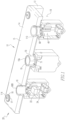
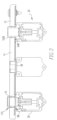
- a circuit breaker module 10 includes a frame 12, a faceplate 14 (shown in part), and a number of circuit breakers 20.
- the frame 12 and the faceplate 14 define an enclosed space 18.
- the circuit breakers 20 are aircraft, or subminiature, circuit breakers 20.
- the circuit breakers 20 include a collar 70 that is disposed about an actuator button (not shown).
- the faceplate 14 includes a number of passages 16, In an exemplary embodiment, the faceplate passages 16 are generally circular, with the exception noted below.
- the circuit breaker collars 70 have an outer radius, with the exception noted below, that generally corresponds to the radius of the faceplate passages 16. In this configuration, the circuit breakers 20 are substantially disposed in the circuit breaker module enclosed space 18 with the collars 70 extending through the faceplate passages 16.
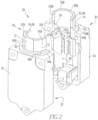
- the circuit breakers 20 include an operating mechanism 22, a conductor assembly 24 (both shown schematically), and a housing assembly 30.
- the operating mechanism 22 includes a number of latches 26 that maintain the operating mechanism in a selected configuration, e.g. an operating configuration prior to an over-current condition.
- each circuit breaker housing assembly includes 30 a first body 32, a second body 34, and a plurality of pins 36.
- the first body 32 and the second body 34 have complimentary shapes. That is, as used herein, "complimentary shapes" mean that the perimeters of the bodies have a substantially similar size and shape.
- Each of the first body 32 and the second body 34 define a cavity 37, 38.
- the first body 32 and the second body 34 are structured to be coupled together with the cavities 37, 38 facing each other so that, when the first body 32 and the second body 34 are coupled, the cavities 37, 38 define a circuit breaker enclosed space 40 ( Figure 1 ).
- the circuit breaker enclosed space 40 is sized and shaped to substantially enclose the operating mechanism 22 and a conductor assembly 24.
- the plurality of pins 36 are structured to align the first body 32 and the second body 34. That is, the plurality of pins 36 are coupling components that cooperate with a plurality of pin cavities 50, described below, disposed on one of, or both, the first body 32 and the second body 34.
- the plurality of pins 36 and the pin cavities 50 are disposed in an alignment pattern.
- the pins 36 are latching pins 36A. That is, an operating mechanism latch 26 is structured to engage a latching pin 36A.
- a "latch pin” is a pin that is used as a latching surface for a circuit breaker operating mechanism 22. As such, when the pins 36 are latching pins 36A, the operating mechanism 22 selectively engages the latch pin 36A.
- the first body 32 and the second body 34 are molded bodies. Further, the plurality of pins 36 are molded as part of either the first body 32 or the second body 34 (molded as part of first body 32 as shown in Figure 2 ). That is, the pins 36 are unitary with one of the first body 32 or the second body 34. In this embodiment, the first body 32 or second body 34, without the unitary pins 36 includes a plurality of pin cavities 50. According to the invention, the pins 36 are unitary to the second body 34. It is understood that, in an exemplary embodiment, there is one pin cavity 50 associated with each pin 36. The pin cavities 50 are disposed in a pattern corresponding to the pins 36 on the other first body 32 or second body 34.
- the first body 32 and the second body 34 are coupled by inserting the distal ends of the pins 36 into the pin cavities 50 and moving the first body 32 and the second body 34 adjacent to each other.
- the first body 32 and the second body 34 are directly coupled at the perimeter when coupled.
- the molded pins 36 do not include a metallic bushing or have such a bushing coupled thereto.
- both the first body 32 and the second body 34 include a plurality of pin cavities 50. It is understood that the pin cavities 50 are disposed in an alignment pattern.
- the pins 36 are separate from the bodies 32, 34. Further there is one pin 36 associated with each pair of pin cavities 50. The pins 36 are inserted into the pin cavities 50 on either the first body 32 or the second body 34. The other body 32 or 34 is then coupled to the body 32 or 34 to which the pins 36 are all ready attached.
- the first body 32 and the second body 34 further include a number of alignment components 60.
- the alignment components 60 include a number of first alignment components 62 and a number of second alignment components 64.
- the first alignment components 62 are disposed on the first body 32 and the second alignment components 64 are disposed on the second body 34.
- the first alignment components 62 and the second alignment components 64 are disposed in a corresponding configuration.
- the first alignment components 62 are lugs 66.
- the lugs 66 are, in an exemplary embodiment, generally semispherical.
- the second alignment components 64 are hollows 68, i.e. cavities, that have a shape generally corresponding to the shape of the lugs 66. That is, in this embodiment, the hollows 68 are also generally semispherical.
- the alignment components 60 are, in an exemplary embodiment, disposed in an alignment pattern.
- the first body 32 and the second body 34 form a collar 70 ( Figure 1 ) having an outer surface 71. That is, in an exemplary embodiment, the first body 32 includes a first collar portion 72 and the second body 34 includes a second collar portion 74. Each collar portion 72, 74 is, in an exemplary embodiment, generally semi-cylindrical. When the first body 32 and the second body 34 are coupled, the collar portions 72, 74 form a passage that extends into the circuit breaker enclosed space 40. In an exemplary embodiment, the outer perimeters of the collar 70 are not circular. That is, each collar portion 72, 74 includes an outer surface 76, 78.
- At least one of the first collar portion outer surface 76 and the second collar portion outer surface 78 includes a generally planar portion 80.
- the collar planar portion 80 extends generally parallel to the longitudinal axis of the collar 70.
- both collar portions 72, 74 include a generally planar portion 80A, 80B on the outer surface 76, 78.
- the collar planar portions 80A, 80B are disposed generally opposite each other.
- the collar 70 acts as an orienting device. That is, a number of the faceplate passages 16 are circuit breaker passages 19 that are shaped to correspond to the shape of the collar outer surface 71.
- the faceplate circuit breaker passages 19 are generally cylindrical except for including at least one, and in an exemplary embodiment two, planar portions 19A (one shown, Figure 1 ).
- the planar portions 19A of the faceplate circuit breaker passages 19 are positioned so that a circuit breaker 20 can only be oriented in one or two positions. That is, as shown, the collar planar portions 80A, 80B and the faceplate passage planar portions 19A are generally the same size.
- the circuit breakers 20 may be installed in two orientations.
- the faceplate passage planar portions 19A however, are positioned so that the circuit breakers 20 are disposed generally parallel to each other.
- each collar portion 72, 74 include a proximal end 90A, 90B and a distal end 92A, 92B.
- Each collar portion proximal end 90A, 90B includes a generally radially extending flange 94A, 94B.
- the shoulder 96 in an exemplary embodiment, is a seat for a resilient O-ring 98.
- each collar distal end 92A, 92B includes a retaining ring groove 100A, 100B.
- the collar retaining ring grooves 100A, 100B form a retaining ring groove 100 that extends about the collar 70.
- the shoulder 96 and the retaining ring groove 100 are spaced a distance, i.e. an axial distance on the collar 70, to snugly correspond to the thickness of the faceplate 14.
- the shoulder 96 and the retaining ring groove 1 00 are spaced a distance so that, when an O-ring 98 is installed on the shoulder 96, the O-ring 98 and the retaining ring groove 100 are spaced a distance, i.e. an axial distance on the collar 70, to snugly correspond to the thickness of the faceplate 14.
- the circuit breakers 20 are assembled with the operating mechanism 22 and the conductor assembly 24 disposed in the circuit breaker enclosed space 40. Each circuit breaker 20 is then disposed in the circuit breaker module enclosed space 18 with the collars 70 extending through the faceplate passages 16. As noted above, the orientation of the circuit breakers 20 is controlled by the location of the faceplate passage planar portions 19A. Further, in an exemplary embodiment, the circuit breaker housing assembly 30 further includes a retaining ring 110. When the retaining ring 110 ( Figure 1 )is installed, the faceplate 14 is compressed. That is, the retaining ring 110 and the shoulder 96, or in an alternative embodiment the O-ring 98 disposed on the shoulder 96, engage the faceplate 14 thereby compressing the faceplate 14.
- the faceplate 14 is a dilatant body 15 that is generally deformable in a direction normal to the plane thereof. Further, the faceplate passages 16 are disposed in a support distribution pattern. In this configuration, when the circuit breakers 20 are coupled to the faceplate 14, as described above, i.e. with the faceplate 14 compressed, the faceplate dilatant body 15 becomes more rigid and is less prone to deflection,
- the faceplate passages 16 further include fastener passages 17.
- the faceplate passages 16 and faceplate fastener passages 17 are disposed in a cooperative support distribution pattern.
- the faceplate 14 is coupled to the frame 12 by compressive fasteners, such as, but not limited to screws 114. When the screws 114 are drawn down on the faceplate 14, the areas about the faceplate fastener passages 17 are compressed thereby increasing the rigidity of the faceplate 14.
Landscapes
- Switch Cases, Indication, And Locking (AREA)
- Breakers (AREA)
- Professional, Industrial, Or Sporting Protective Garments (AREA)
- Physics & Mathematics (AREA)
- Electromagnetism (AREA)
Claims (13)
- Leitungsschutzschalter (20) mit einer Gehäuseanordnung (30),wobei der Leitungsschutzschalter (20) einen Operationsmechanismus (22) und eine Leiteranordnung (24) beinhaltet, wobei die Leitungsschutzschaltergehäuseanordnung (30) aufweist:einen ersten Körper (32), der einen ersten Körperhohlraum (37) definiert, wobei der erste Körper (32) geformt ist und mehrere Stifthohlräume (50) beinhaltet;einen zweiten Körper (34), der einen zweiten Körperhohlraum (38) definiert, wobei der zweite Körper (34) so geformt ist, dass er mehrere Stifte (36) beinhaltet, die mit dem zweiten Körper (34) einheitlich sind,wobei der erste Körper (32) und der zweite Körper (34) komplementäre Formen haben;wobei die Stifte (36) und Stifthohlräume (50) in einem Ausrichtungsmuster angeordnet sind;
undwobei der erste Körper (32) und der zweite Körper (34) so miteinander gekoppelt sind, dass der erste Körperhohlraum (37) und der zweite Körperhohlraum (38) kooperieren, um einen umschlossenen Raum (40) zu definieren, der strukturiert ist, um den Operationsmechanismus (22) und die Leiteranordnung (24) des Leitungsschutzschalters (20) aufzunehmen, wobei wenn der erste Körper (32) und der zweite Körper (34) miteinander gekoppelt sind, wobei die Stifte (36) keine metallischen Buchse beinhalten oder mit einer solchen Buchse gekoppelt sind,der Leitungsschutzschalter dadurch gekennzeichnet ist, dasseine Anzahl von Stiften (36) Verriegelungsstifte (36A) sind, die den ersten Körper (32) und den zweiten Körper (34) selektiv koppeln; unddie mehreren Verriegelungsstifte (36A) in den jeweiligen mehreren Stifthohlräumen (50) aufgenommen und selektiv durch den Operationsmechanismus (22) in Eingriff gebracht werden. - Leitungsschutzschalter gemäß Anspruch 1, wobei:der erste Körper (32) eine Anzahl von ersten Ausrichtungskomponenten (62) beinhaltet;der zweite Körper (34) eine Anzahl von zweiten Ausrichtungskomponenten (64) beinhaltet; unddie ersten Ausrichtungskomponenten (62) und die zweiten Ausrichtungskomponenten (64) in einer entsprechenden Konfiguration angeordnet sind.
- Leitungsschutzschalter gemäß Anspruch 2, wobei:die ersten Ausrichtungskomponenten (62) Nasen (66) sind; unddie zweiten Ausrichtungskomponenten (64) Hohlräume (68) sind.
- Leitungsschutzschalter gemäß Anspruch 1, wobei:der erste Körper (32) einen ersten Kragenabschnitt (72) mit einer ersten Kragenabschnittsaußenfläche (76) beinhaltet;der zweite Körper (34) einen zweiten Kragenabschnitt (74) mit einer zweiten Kragenabschnittsaußenfläche (78) beinhaltet;wobei, wenn der erste Körper (32) und der zweite Körper (34) gekoppelt sind, der erste Kragenabschnitt (72) und der zweite Kragenabschnitt (74) einen Kragen (70) bilden, der einen Durchgang in den umschlossenen Raum (18) definiert;wobei der erste Kragenabschnitt (72) und der zweite Kragenabschnitt (74) jeweils im Allgemeinen halbzylindrisch sind; undwobei mindestens eine der ersten Kragenabschnittsaußenfläche (76) und der zweiten Kragenabschnittsaußenfläche (78) einen im Allgemeinen planaren Abschnitt beinhaltet.
- Leitungsschutzschalter gemäß Anspruch 4, wobei:die erste Kragenabschnittsaußenfläche (76) und die zweite Kragenabschnittsaußenfläche (78) jeweils einen im Allgemeinen planaren Abschnitt (80) beinhalten; undwobei, wenn der erste Körper (32) und der zweite Körper (34) gekoppelt sind, der planare Abschnitt (80A) des ersten Kragenabschnitts und der planare Abschnitt (80B) des zweiten Kragenabschnitts im Allgemeinen einander gegenüberliegend angeordnet sind.
- Leitungsschutzschalter gemäß Anspruch 4, wobei:
der Schutzschalter (20) so strukturiert ist, dass er mit einer im Allgemeinen planaren Abdeckung (14) gekoppelt ist, wobei die Abdeckung (14) eine Anzahl von Durchgängen (16) entsprechend dem Kragen (70) beinhaltet, wobei die Abdeckung (14) eine Dicke hat, und wobei:der erste Kragenabschnitt (72) und der zweite Kragenabschnitt (74) jeweils ein proximales Ende (90A, 908) und ein distales Ende (92A, 928) beinhalten;das proximale Ende (90A) des ersten Kragenabschnitts und das proximale Ende (90B) des zweiten Kragenabschnitts jeweils einen radialen Flansch (94A, 94B) beinhalten;wobei, wenn der erste Körper (32) und der zweite Körper (34) gekoppelt sind, der Flansch (94A) des ersten Kragenabschnitts und der Flansch (94B) des zweiten Kragenabschnitts eine Schulter (96) definieren, die sich um den Kragen (70) erstreckt;das distale Ende (92A) des ersten Kragenabschnitts und das distale Ende (92B) des zweiten Kragenabschnitts eine Halteringnut (100) beinhaltet;die Schulter (96) und die Halteringnut (100) jeweils beabstandet sind, um festsitzend der Dicke der Abdeckung (14) zu entsprechen; undein O-Ring (98) um den Kragen (70) und an der Schulter (96) angeordnet ist. - Schutzschaltermodul (10), aufweisend:eine Abdeckung (14) mit einer Anzahl von Durchgängen (16);eine Anzahl Leitungsschutzschalter (20) gemäß Anspruch 1.
- Schutzschaltermodul (10) gemäß Anspruch 7, wobei:der erste Körper (32) eine Anzahl von ersten Ausrichtungskomponenten (62) beinhaltet;der zweite Körper (34) eine Anzahl von zweiten Ausrichtungskomponenten (64) beinhaltet; unddie ersten Ausrichtungskomponenten (62) und die zweiten Ausrichtungskomponenten (64) in einer entsprechenden Konfiguration angeordnet sind.
- Schutzschaltermodul (10) gemäß Anspruch 7, wobei:der erste Körper (32) einen ersten Kragenabschnitt (72) mit einer ersten Kragenabschnittsaußenfläche (76) beinhaltet;der zweite Körper (34) einen zweiten Kragenabschnitt (74) mit einer zweiten Kragenabschnittsaußenfläche (78) beinhaltet;wobei, wenn der erste Körper (32) und der zweite Körper (34) gekoppelt sind, der erste Kragenabschnitt (72) und der zweite Kragenabschnitt (74) einen Kragen (70) bilden, der einen Durchgang in den umschlossenen Raum (18) definiert;wobei der erste Kragenabschnitt (72) und der zweite Kragenabschnitt (74) jeweils im Allgemeinen halbzylindrisch sind; undwobei mindestens eine der ersten Kragenabschnittsaußenfläche (76) und der zweiten Kragenabschnittsaußenfläche (78) einen im Allgemeinen planaren Abschnitt (80) beinhaltet.
- Schutzschaltermodul (10) gemäß Anspruch 9, wobei:jede der ersten Kragenabschnittsaußenfläche (76) und der zweiten Kragenabschnittsaußenfläche (78) einen im Allgemeinen planaren Abschnitt (80A, 80B) beinhaltet; undwobei, wenn der erste Körper (32) und der zweite Körper (34) gekoppelt sind, der planare Abschnitt (80A) des ersten Kragenabschnitts und der planare Abschnitt (80B) des zweiten Kragenabschnitts im Allgemeinen einander gegenüberliegend angeordnet sind.
- Schutzschaltermodul (10) gemäß Anspruch 9, wobei:
die Abdeckung (14) eine Dicke hat, und wobei:der erste Kragenabschnitt (72) und der zweite Kragenabschnitt (74) jeweils ein proximales Ende (90A, 908) und ein distales Ende (92A, 928) beinhalten;das proximale Ende (90A) des ersten Kragenabschnitts und das proximale Ende (90B) des zweiten Kragenabschnitts jeweils einen radialen Flansch (94A, 94B) beinhalten;wobei, wenn der erste Körper (32) und der zweite Körper (34) gekoppelt sind, der Flansch (94A) des ersten Kragenabschnitts und der Flansch (94B) des zweiten Kragenabschnitts eine Schulter (96) definieren, die sich um den Kragen (70) erstreckt;das distale Ende (92A) des ersten Kragenabschnitts und das distale Ende (92B) des zweiten Kragenabschnitts jeweils eine Halteringnut (100) beinhalten;die Schulter (96) und die Halteringnut (100) jeweils beabstandet sind, um festsitzend der Dicke der Abdeckung (14) zu entsprechen; undein O-Ring (98) um den Kragen (70) und an der Schulter (96) angeordnet ist. - Schutzschaltermodul (10) gemäß Anspruch 7, wobei:die Abdeckung (14) ein dilatanter Körper (15) ist, der im Allgemeinen in Richtung senkrecht zu seiner Ebene verformbar ist, wobei der dilatante Körper (15) steifer wird, wenn Druck darauf ausgeübt wird; undwobei die Abdeckungsdurchgänge (16) eine Anzahl von Befestigungsmitteldurchgängen (17) beinhalten, die in einem Stützverteilungsmuster angeordnet sind.
- Schutzschaltermodul (10) gemäß Anspruch 7, wobei:die Abdeckung (14) ein dilatanter Körper (15) ist, der im Allgemeinen in Richtung senkrecht zu seiner Ebene verformbar ist, wobei der dilatante Körper (15) steifer wird, wenn Druck darauf ausgeübt wird; unddie Abdeckungsdurchgänge (16) eine Anzahl von Schutzschalterdurchgängen (17) beinhalten, die in einem Stützverteilungsmuster angeordnet sind.
Applications Claiming Priority (2)
| Application Number | Priority Date | Filing Date | Title |
|---|---|---|---|
| US201361882689P | 2013-09-26 | 2013-09-26 | |
| PCT/US2014/056046 WO2015047820A1 (en) | 2013-09-26 | 2014-09-17 | Circuit breaker module with plug-in circuit breakers |
Publications (3)
| Publication Number | Publication Date |
|---|---|
| EP3050068A1 EP3050068A1 (de) | 2016-08-03 |
| EP3050068A4 EP3050068A4 (de) | 2017-04-12 |
| EP3050068B1 true EP3050068B1 (de) | 2023-06-21 |
Family
ID=52689997
Family Applications (1)
| Application Number | Title | Priority Date | Filing Date |
|---|---|---|---|
| EP14849548.4A Active EP3050068B1 (de) | 2013-09-26 | 2014-09-17 | Schutzschaltermodul mit steckbaren schutzschaltern |
Country Status (4)
| Country | Link |
|---|---|
| US (1) | US9373472B2 (de) |
| EP (1) | EP3050068B1 (de) |
| CN (1) | CN105593960B (de) |
| WO (1) | WO2015047820A1 (de) |
Family Cites Families (14)
| Publication number | Priority date | Publication date | Assignee | Title |
|---|---|---|---|---|
| US3329793A (en) * | 1966-01-28 | 1967-07-04 | Heinemann Electric Co | Circuit breaker case |
| DE1665578A1 (de) * | 1966-03-23 | 1971-03-18 | Siemens Ag | Gehaeuse zum wahlweisen Einbau verschiedenartiger Schalter fuer Lichtrufanlagen od.dgl. |
| US4153055A (en) | 1975-07-31 | 1979-05-08 | Northern Illinois Research, Inc. | Plastic composition manufacture thereof, and pad formed therewith |
| FR2656464B1 (fr) * | 1989-12-22 | 1992-03-27 | Merlin Gerin | Boitier isolant pour un disjoncteur differentiel a neutre passant ou sectionne. |
| US5000317A (en) | 1990-03-26 | 1991-03-19 | Cich Joel A | Sports glove storage ball |
| US5343179A (en) * | 1993-01-29 | 1994-08-30 | Eaton Corporation | Miniaturized solenoid operated trip device |
| ITMI20012586A1 (it) | 2001-12-10 | 2003-06-10 | Abb Service Srl | Polo elettrico per un interruttore di potenza di bassa tensione, e relativo interruttore |
| DE102004043469B4 (de) * | 2004-09-08 | 2007-07-26 | Siemens Ag | Halterungseinrichtung mit einem darauf befestigten Schaltgerät |
| US7170376B2 (en) | 2004-12-09 | 2007-01-30 | Eaton Corporation | Electrical switching apparatus including a housing and a trip circuit forming a composite structure |
| US7804201B1 (en) | 2009-01-28 | 2010-09-28 | Finley Lee Ledbetter | Portable remote switch operator system |
| US7994882B2 (en) * | 2009-04-18 | 2011-08-09 | General Electric Company | Space allocation within a circuit breaker |
| IT1399666B1 (it) * | 2010-03-30 | 2013-04-26 | Bticino Spa | Apparecchio per il controllo e/o la distribuzione di energia elettrica comprendente un dispositivo protettivo antipolvere |
| US8514552B2 (en) * | 2010-12-17 | 2013-08-20 | Eaton Corporation | Electrical system and matrix assembly therefor |
| KR101513208B1 (ko) * | 2013-11-08 | 2015-04-17 | 엘에스산전 주식회사 | 배선용 차단기 |
-
2014
- 2014-09-17 US US14/488,701 patent/US9373472B2/en active Active
- 2014-09-17 CN CN201480053403.0A patent/CN105593960B/zh active Active
- 2014-09-17 EP EP14849548.4A patent/EP3050068B1/de active Active
- 2014-09-17 WO PCT/US2014/056046 patent/WO2015047820A1/en not_active Ceased
Also Published As
| Publication number | Publication date |
|---|---|
| CN105593960B (zh) | 2018-09-07 |
| EP3050068A4 (de) | 2017-04-12 |
| US20150083560A1 (en) | 2015-03-26 |
| CN105593960A (zh) | 2016-05-18 |
| WO2015047820A1 (en) | 2015-04-02 |
| EP3050068A1 (de) | 2016-08-03 |
| US9373472B2 (en) | 2016-06-21 |
Similar Documents
| Publication | Publication Date | Title |
|---|---|---|
| US10044117B2 (en) | MCCB current limiter lug adapter | |
| EP2929554B1 (de) | Schutzschalterklemmenabschirmung mit stellungsanzeige | |
| EP3913653B1 (de) | Gelenkige clinchverbindung für schutzschalter mit gegossenem gehäuse | |
| US10312037B1 (en) | Rotary motion switching apparatus usable with circuit interrupter | |
| EP3050068B1 (de) | Schutzschaltermodul mit steckbaren schutzschaltern | |
| US10163586B2 (en) | Momentary structure for mini toggle switch | |
| US9093230B2 (en) | Hidden/sliding door system for field-installed accessory access | |
| US12243698B2 (en) | Non-electrical device for replacing a current sensor in an arc-extinguishing chamber of a switch-disconnector, and a switch-disconnector comprising such a non-electrical device | |
| US9136081B2 (en) | D/C trip assembly | |
| US9947498B2 (en) | Electrical switching apparatus and clinch joint assembly therefor | |
| CA2920300C (en) | Power module | |
| US9293282B2 (en) | Moving seal with arc creepage surface for an air circuit breaker | |
| US7026560B2 (en) | Separable, flexible electrical connection arrangement | |
| WO2025119540A1 (de) | Elektrisches gerät | |
| EP3130001A1 (de) | Mehrzweckhalterung für eine elektrische schaltvorrichtung |
Legal Events
| Date | Code | Title | Description |
|---|---|---|---|
| PUAI | Public reference made under article 153(3) epc to a published international application that has entered the european phase |
Free format text: ORIGINAL CODE: 0009012 |
|
| 17P | Request for examination filed |
Effective date: 20160331 |
|
| AK | Designated contracting states |
Kind code of ref document: A1 Designated state(s): AL AT BE BG CH CY CZ DE DK EE ES FI FR GB GR HR HU IE IS IT LI LT LU LV MC MK MT NL NO PL PT RO RS SE SI SK SM TR |
|
| AX | Request for extension of the european patent |
Extension state: BA ME |
|
| DAX | Request for extension of the european patent (deleted) | ||
| A4 | Supplementary search report drawn up and despatched |
Effective date: 20170310 |
|
| RIC1 | Information provided on ipc code assigned before grant |
Ipc: H01H 71/02 20060101ALN20170306BHEP Ipc: H01H 21/04 20060101AFI20170306BHEP |
|
| STAA | Information on the status of an ep patent application or granted ep patent |
Free format text: STATUS: EXAMINATION IS IN PROGRESS |
|
| 17Q | First examination report despatched |
Effective date: 20210112 |
|
| REG | Reference to a national code |
Ref country code: DE Ref legal event code: R079 Free format text: PREVIOUS MAIN CLASS: H01H0021040000 Ipc: H01H0071020000 Ref country code: DE Ref legal event code: R079 Ref document number: 602014087422 Country of ref document: DE Free format text: PREVIOUS MAIN CLASS: H01H0021040000 Ipc: H01H0071020000 |
|
| GRAP | Despatch of communication of intention to grant a patent |
Free format text: ORIGINAL CODE: EPIDOSNIGR1 |
|
| STAA | Information on the status of an ep patent application or granted ep patent |
Free format text: STATUS: GRANT OF PATENT IS INTENDED |
|
| RIC1 | Information provided on ipc code assigned before grant |
Ipc: H01H 9/04 19680901ALN20230110BHEP Ipc: H01H 71/02 19680901AFI20230110BHEP |
|
| INTG | Intention to grant announced |
Effective date: 20230124 |
|
| GRAS | Grant fee paid |
Free format text: ORIGINAL CODE: EPIDOSNIGR3 |
|
| GRAA | (expected) grant |
Free format text: ORIGINAL CODE: 0009210 |
|
| STAA | Information on the status of an ep patent application or granted ep patent |
Free format text: STATUS: THE PATENT HAS BEEN GRANTED |
|
| AK | Designated contracting states |
Kind code of ref document: B1 Designated state(s): AL AT BE BG CH CY CZ DE DK EE ES FI FR GB GR HR HU IE IS IT LI LT LU LV MC MK MT NL NO PL PT RO RS SE SI SK SM TR |
|
| REG | Reference to a national code |
Ref country code: CH Ref legal event code: EP |
|
| REG | Reference to a national code |
Ref country code: DE Ref legal event code: R096 Ref document number: 602014087422 Country of ref document: DE |
|
| REG | Reference to a national code |
Ref country code: AT Ref legal event code: REF Ref document number: 1581517 Country of ref document: AT Kind code of ref document: T Effective date: 20230715 |
|
| REG | Reference to a national code |
Ref country code: IE Ref legal event code: FG4D |
|
| REG | Reference to a national code |
Ref country code: LT Ref legal event code: MG9D |
|
| REG | Reference to a national code |
Ref country code: NL Ref legal event code: MP Effective date: 20230621 |
|
| PG25 | Lapsed in a contracting state [announced via postgrant information from national office to epo] |
Ref country code: SE Free format text: LAPSE BECAUSE OF FAILURE TO SUBMIT A TRANSLATION OF THE DESCRIPTION OR TO PAY THE FEE WITHIN THE PRESCRIBED TIME-LIMIT Effective date: 20230621 Ref country code: NO Free format text: LAPSE BECAUSE OF FAILURE TO SUBMIT A TRANSLATION OF THE DESCRIPTION OR TO PAY THE FEE WITHIN THE PRESCRIBED TIME-LIMIT Effective date: 20230921 |
|
| REG | Reference to a national code |
Ref country code: AT Ref legal event code: MK05 Ref document number: 1581517 Country of ref document: AT Kind code of ref document: T Effective date: 20230621 |
|
| PG25 | Lapsed in a contracting state [announced via postgrant information from national office to epo] |
Ref country code: RS Free format text: LAPSE BECAUSE OF FAILURE TO SUBMIT A TRANSLATION OF THE DESCRIPTION OR TO PAY THE FEE WITHIN THE PRESCRIBED TIME-LIMIT Effective date: 20230621 Ref country code: NL Free format text: LAPSE BECAUSE OF FAILURE TO SUBMIT A TRANSLATION OF THE DESCRIPTION OR TO PAY THE FEE WITHIN THE PRESCRIBED TIME-LIMIT Effective date: 20230621 Ref country code: LV Free format text: LAPSE BECAUSE OF FAILURE TO SUBMIT A TRANSLATION OF THE DESCRIPTION OR TO PAY THE FEE WITHIN THE PRESCRIBED TIME-LIMIT Effective date: 20230621 Ref country code: LT Free format text: LAPSE BECAUSE OF FAILURE TO SUBMIT A TRANSLATION OF THE DESCRIPTION OR TO PAY THE FEE WITHIN THE PRESCRIBED TIME-LIMIT Effective date: 20230621 Ref country code: HR Free format text: LAPSE BECAUSE OF FAILURE TO SUBMIT A TRANSLATION OF THE DESCRIPTION OR TO PAY THE FEE WITHIN THE PRESCRIBED TIME-LIMIT Effective date: 20230621 Ref country code: GR Free format text: LAPSE BECAUSE OF FAILURE TO SUBMIT A TRANSLATION OF THE DESCRIPTION OR TO PAY THE FEE WITHIN THE PRESCRIBED TIME-LIMIT Effective date: 20230922 |
|
| PG25 | Lapsed in a contracting state [announced via postgrant information from national office to epo] |
Ref country code: FI Free format text: LAPSE BECAUSE OF FAILURE TO SUBMIT A TRANSLATION OF THE DESCRIPTION OR TO PAY THE FEE WITHIN THE PRESCRIBED TIME-LIMIT Effective date: 20230621 |
|
| PG25 | Lapsed in a contracting state [announced via postgrant information from national office to epo] |
Ref country code: SK Free format text: LAPSE BECAUSE OF FAILURE TO SUBMIT A TRANSLATION OF THE DESCRIPTION OR TO PAY THE FEE WITHIN THE PRESCRIBED TIME-LIMIT Effective date: 20230621 |
|
| PG25 | Lapsed in a contracting state [announced via postgrant information from national office to epo] |
Ref country code: ES Free format text: LAPSE BECAUSE OF FAILURE TO SUBMIT A TRANSLATION OF THE DESCRIPTION OR TO PAY THE FEE WITHIN THE PRESCRIBED TIME-LIMIT Effective date: 20230621 |
|
| PG25 | Lapsed in a contracting state [announced via postgrant information from national office to epo] |
Ref country code: IS Free format text: LAPSE BECAUSE OF FAILURE TO SUBMIT A TRANSLATION OF THE DESCRIPTION OR TO PAY THE FEE WITHIN THE PRESCRIBED TIME-LIMIT Effective date: 20231021 |
|
| PG25 | Lapsed in a contracting state [announced via postgrant information from national office to epo] |
Ref country code: SM Free format text: LAPSE BECAUSE OF FAILURE TO SUBMIT A TRANSLATION OF THE DESCRIPTION OR TO PAY THE FEE WITHIN THE PRESCRIBED TIME-LIMIT Effective date: 20230621 Ref country code: SK Free format text: LAPSE BECAUSE OF FAILURE TO SUBMIT A TRANSLATION OF THE DESCRIPTION OR TO PAY THE FEE WITHIN THE PRESCRIBED TIME-LIMIT Effective date: 20230621 Ref country code: RO Free format text: LAPSE BECAUSE OF FAILURE TO SUBMIT A TRANSLATION OF THE DESCRIPTION OR TO PAY THE FEE WITHIN THE PRESCRIBED TIME-LIMIT Effective date: 20230621 Ref country code: PT Free format text: LAPSE BECAUSE OF FAILURE TO SUBMIT A TRANSLATION OF THE DESCRIPTION OR TO PAY THE FEE WITHIN THE PRESCRIBED TIME-LIMIT Effective date: 20231023 Ref country code: IS Free format text: LAPSE BECAUSE OF FAILURE TO SUBMIT A TRANSLATION OF THE DESCRIPTION OR TO PAY THE FEE WITHIN THE PRESCRIBED TIME-LIMIT Effective date: 20231021 Ref country code: ES Free format text: LAPSE BECAUSE OF FAILURE TO SUBMIT A TRANSLATION OF THE DESCRIPTION OR TO PAY THE FEE WITHIN THE PRESCRIBED TIME-LIMIT Effective date: 20230621 Ref country code: EE Free format text: LAPSE BECAUSE OF FAILURE TO SUBMIT A TRANSLATION OF THE DESCRIPTION OR TO PAY THE FEE WITHIN THE PRESCRIBED TIME-LIMIT Effective date: 20230621 Ref country code: CZ Free format text: LAPSE BECAUSE OF FAILURE TO SUBMIT A TRANSLATION OF THE DESCRIPTION OR TO PAY THE FEE WITHIN THE PRESCRIBED TIME-LIMIT Effective date: 20230621 Ref country code: AT Free format text: LAPSE BECAUSE OF FAILURE TO SUBMIT A TRANSLATION OF THE DESCRIPTION OR TO PAY THE FEE WITHIN THE PRESCRIBED TIME-LIMIT Effective date: 20230621 |
|
| PG25 | Lapsed in a contracting state [announced via postgrant information from national office to epo] |
Ref country code: PL Free format text: LAPSE BECAUSE OF FAILURE TO SUBMIT A TRANSLATION OF THE DESCRIPTION OR TO PAY THE FEE WITHIN THE PRESCRIBED TIME-LIMIT Effective date: 20230621 |
|
| REG | Reference to a national code |
Ref country code: DE Ref legal event code: R097 Ref document number: 602014087422 Country of ref document: DE |
|
| PLBE | No opposition filed within time limit |
Free format text: ORIGINAL CODE: 0009261 |
|
| STAA | Information on the status of an ep patent application or granted ep patent |
Free format text: STATUS: NO OPPOSITION FILED WITHIN TIME LIMIT |
|
| PG25 | Lapsed in a contracting state [announced via postgrant information from national office to epo] |
Ref country code: DK Free format text: LAPSE BECAUSE OF FAILURE TO SUBMIT A TRANSLATION OF THE DESCRIPTION OR TO PAY THE FEE WITHIN THE PRESCRIBED TIME-LIMIT Effective date: 20230621 |
|
| REG | Reference to a national code |
Ref country code: CH Ref legal event code: PL |
|
| PG25 | Lapsed in a contracting state [announced via postgrant information from national office to epo] |
Ref country code: SI Free format text: LAPSE BECAUSE OF FAILURE TO SUBMIT A TRANSLATION OF THE DESCRIPTION OR TO PAY THE FEE WITHIN THE PRESCRIBED TIME-LIMIT Effective date: 20230621 |
|
| PG25 | Lapsed in a contracting state [announced via postgrant information from national office to epo] |
Ref country code: LU Free format text: LAPSE BECAUSE OF NON-PAYMENT OF DUE FEES Effective date: 20230917 |
|
| REG | Reference to a national code |
Ref country code: BE Ref legal event code: MM Effective date: 20230930 |
|
| 26N | No opposition filed |
Effective date: 20240322 |
|
| PG25 | Lapsed in a contracting state [announced via postgrant information from national office to epo] |
Ref country code: SI Free format text: LAPSE BECAUSE OF FAILURE TO SUBMIT A TRANSLATION OF THE DESCRIPTION OR TO PAY THE FEE WITHIN THE PRESCRIBED TIME-LIMIT Effective date: 20230621 Ref country code: LU Free format text: LAPSE BECAUSE OF NON-PAYMENT OF DUE FEES Effective date: 20230917 Ref country code: IT Free format text: LAPSE BECAUSE OF FAILURE TO SUBMIT A TRANSLATION OF THE DESCRIPTION OR TO PAY THE FEE WITHIN THE PRESCRIBED TIME-LIMIT Effective date: 20230621 Ref country code: MC Free format text: LAPSE BECAUSE OF FAILURE TO SUBMIT A TRANSLATION OF THE DESCRIPTION OR TO PAY THE FEE WITHIN THE PRESCRIBED TIME-LIMIT Effective date: 20230621 |
|
| REG | Reference to a national code |
Ref country code: IE Ref legal event code: MM4A |
|
| PG25 | Lapsed in a contracting state [announced via postgrant information from national office to epo] |
Ref country code: IE Free format text: LAPSE BECAUSE OF NON-PAYMENT OF DUE FEES Effective date: 20230917 |
|
| PG25 | Lapsed in a contracting state [announced via postgrant information from national office to epo] |
Ref country code: CH Free format text: LAPSE BECAUSE OF NON-PAYMENT OF DUE FEES Effective date: 20230930 |
|
| PG25 | Lapsed in a contracting state [announced via postgrant information from national office to epo] |
Ref country code: IE Free format text: LAPSE BECAUSE OF NON-PAYMENT OF DUE FEES Effective date: 20230917 Ref country code: CH Free format text: LAPSE BECAUSE OF NON-PAYMENT OF DUE FEES Effective date: 20230930 |
|
| PG25 | Lapsed in a contracting state [announced via postgrant information from national office to epo] |
Ref country code: BE Free format text: LAPSE BECAUSE OF NON-PAYMENT OF DUE FEES Effective date: 20230930 |
|
| PG25 | Lapsed in a contracting state [announced via postgrant information from national office to epo] |
Ref country code: BG Free format text: LAPSE BECAUSE OF FAILURE TO SUBMIT A TRANSLATION OF THE DESCRIPTION OR TO PAY THE FEE WITHIN THE PRESCRIBED TIME-LIMIT Effective date: 20230621 |
|
| PG25 | Lapsed in a contracting state [announced via postgrant information from national office to epo] |
Ref country code: BG Free format text: LAPSE BECAUSE OF FAILURE TO SUBMIT A TRANSLATION OF THE DESCRIPTION OR TO PAY THE FEE WITHIN THE PRESCRIBED TIME-LIMIT Effective date: 20230621 |
|
| PG25 | Lapsed in a contracting state [announced via postgrant information from national office to epo] |
Ref country code: CY Free format text: LAPSE BECAUSE OF FAILURE TO SUBMIT A TRANSLATION OF THE DESCRIPTION OR TO PAY THE FEE WITHIN THE PRESCRIBED TIME-LIMIT; INVALID AB INITIO Effective date: 20140917 |
|
| PG25 | Lapsed in a contracting state [announced via postgrant information from national office to epo] |
Ref country code: HU Free format text: LAPSE BECAUSE OF FAILURE TO SUBMIT A TRANSLATION OF THE DESCRIPTION OR TO PAY THE FEE WITHIN THE PRESCRIBED TIME-LIMIT; INVALID AB INITIO Effective date: 20140917 |
|
| REG | Reference to a national code |
Ref country code: DE Ref legal event code: R081 Ref document number: 602014087422 Country of ref document: DE Owner name: SAFRAN ELECTRICAL & POWER USA, LLC, DENTON, US Free format text: FORMER OWNER: LABINAL, LLC, DENTON, TX, US |
|
| PGFP | Annual fee paid to national office [announced via postgrant information from national office to epo] |
Ref country code: DE Payment date: 20250919 Year of fee payment: 12 |
|
| PGFP | Annual fee paid to national office [announced via postgrant information from national office to epo] |
Ref country code: GB Payment date: 20250923 Year of fee payment: 12 |
|
| PGFP | Annual fee paid to national office [announced via postgrant information from national office to epo] |
Ref country code: FR Payment date: 20250917 Year of fee payment: 12 |
|
| PG25 | Lapsed in a contracting state [announced via postgrant information from national office to epo] |
Ref country code: TR Free format text: LAPSE BECAUSE OF FAILURE TO SUBMIT A TRANSLATION OF THE DESCRIPTION OR TO PAY THE FEE WITHIN THE PRESCRIBED TIME-LIMIT Effective date: 20230621 |