EP3050070B1 - Moyen de commutation thermique, dispositif de chauffage et procédé de montage d'un moyen de commutation thermique sur un moyen de chauffage - Google Patents
Moyen de commutation thermique, dispositif de chauffage et procédé de montage d'un moyen de commutation thermique sur un moyen de chauffage Download PDFInfo
- Publication number
- EP3050070B1 EP3050070B1 EP14812169.2A EP14812169A EP3050070B1 EP 3050070 B1 EP3050070 B1 EP 3050070B1 EP 14812169 A EP14812169 A EP 14812169A EP 3050070 B1 EP3050070 B1 EP 3050070B1
- Authority
- EP
- European Patent Office
- Prior art keywords
- switching device
- carrier
- thermal switching
- thermal
- laser
- Prior art date
- Legal status (The legal status is an assumption and is not a legal conclusion. Google has not performed a legal analysis and makes no representation as to the accuracy of the status listed.)
- Active
Links
Images





Classifications
-
- H—ELECTRICITY
- H01—ELECTRIC ELEMENTS
- H01H—ELECTRIC SWITCHES; RELAYS; SELECTORS; EMERGENCY PROTECTIVE DEVICES
- H01H37/00—Thermally-actuated switches
- H01H37/02—Details
- H01H37/04—Bases; Housings; Mountings
-
- H—ELECTRICITY
- H01—ELECTRIC ELEMENTS
- H01H—ELECTRIC SWITCHES; RELAYS; SELECTORS; EMERGENCY PROTECTIVE DEVICES
- H01H37/00—Thermally-actuated switches
- H01H37/02—Details
- H01H37/04—Bases; Housings; Mountings
- H01H37/043—Mountings on controlled apparatus
-
- B—PERFORMING OPERATIONS; TRANSPORTING
- B23—MACHINE TOOLS; METAL-WORKING NOT OTHERWISE PROVIDED FOR
- B23K—SOLDERING OR UNSOLDERING; WELDING; CLADDING OR PLATING BY SOLDERING OR WELDING; CUTTING BY APPLYING HEAT LOCALLY, e.g. FLAME CUTTING; WORKING BY LASER BEAM
- B23K26/00—Working by laser beam, e.g. welding, cutting or boring
- B23K26/20—Bonding
- B23K26/21—Bonding by welding
-
- B—PERFORMING OPERATIONS; TRANSPORTING
- B23—MACHINE TOOLS; METAL-WORKING NOT OTHERWISE PROVIDED FOR
- B23K—SOLDERING OR UNSOLDERING; WELDING; CLADDING OR PLATING BY SOLDERING OR WELDING; CUTTING BY APPLYING HEAT LOCALLY, e.g. FLAME CUTTING; WORKING BY LASER BEAM
- B23K26/00—Working by laser beam, e.g. welding, cutting or boring
- B23K26/20—Bonding
- B23K26/21—Bonding by welding
- B23K26/24—Seam welding
- B23K26/242—Fillet welding, i.e. involving a weld of substantially triangular cross section joining two parts
-
- B—PERFORMING OPERATIONS; TRANSPORTING
- B23—MACHINE TOOLS; METAL-WORKING NOT OTHERWISE PROVIDED FOR
- B23K—SOLDERING OR UNSOLDERING; WELDING; CLADDING OR PLATING BY SOLDERING OR WELDING; CUTTING BY APPLYING HEAT LOCALLY, e.g. FLAME CUTTING; WORKING BY LASER BEAM
- B23K33/00—Specially-profiled edge portions of workpieces for making soldering or welding connections; Filling the seams formed thereby
- B23K33/004—Filling of continuous seams
-
- B—PERFORMING OPERATIONS; TRANSPORTING
- B23—MACHINE TOOLS; METAL-WORKING NOT OTHERWISE PROVIDED FOR
- B23K—SOLDERING OR UNSOLDERING; WELDING; CLADDING OR PLATING BY SOLDERING OR WELDING; CUTTING BY APPLYING HEAT LOCALLY, e.g. FLAME CUTTING; WORKING BY LASER BEAM
- B23K2101/00—Articles made by soldering, welding or cutting
- B23K2101/36—Electric or electronic devices
-
- H—ELECTRICITY
- H01—ELECTRIC ELEMENTS
- H01H—ELECTRIC SWITCHES; RELAYS; SELECTORS; EMERGENCY PROTECTIVE DEVICES
- H01H37/00—Thermally-actuated switches
- H01H37/002—Thermally-actuated switches combined with protective means
Definitions
- the present invention relates to a thermal switching device according to the preamble of claim 1 and a heater assembly according to the preamble of claim 15. Further, the present invention relates to a method for fixing a thermal switching device to a heating device by means of laser welding according to claim 18.
- Thermal switching devices of the type of interest are, in particular, temperature regulators, temperature limiters, temperature monitors or temperature protectors, which are in thermal contact with the heating device of a commodity and automatically execute a switching operation when a predetermined temperature threshold is exceeded.
- thermal switching devices are commonly used in commodities, e.g. Kettle, water heater, coffee machines, washing machines, iron and the like used.
- a bimetallic snap disk which serves as temperature-dependent two stable snap positions (deflections) (bistable snap-action bimetallic disk) usually serves as a temperature sensor and, depending on its respective deflection, a circuit is opened or closed again.
- a melting device instead of the Bimetallschnappulation a melting device z.
- B. enamel pellet by means of which when a temperature is exceeded, a circuit can be interrupted.
- a corresponding thermal switching device in the form of a thermal temperature controller and a thermal thermal fuse is for example from DE 197 06 316 C2 seen.
- the thermal switching device comprises a thermally conductive, preferably plate-shaped support on which the housing or the base of the thermal switching device is located and which also serves for attachment to the surface of the heating device.
- the plate-shaped support For attachment of the plate-shaped support, this usually has at least one, preferably two opposing mounting tabs, each with a bore.
- a corresponding carrier plate is for example from the DE 20 2005 019 880 U1 known.
- the thermal switching device is attached, for example, to a pre-installed on the heater threaded bolt by means of a nut. This type of attachment can only be done manually. It is not suitable for automation.
- an air gap often occurs between the carrier plate and the heating device, which leads to an only moderate heat transfer and thereby to increased reaction times of the thermal switching device.
- the attachment tabs of the carrier must be sufficiently large dimensions for receiving the bore for the threaded bolt, which in turn means that this type of attachment requires an increased space requirement.
- heaters for utensils as well as the support of thermal switching devices often consist of aluminum.
- a thermal switching device according to the preamble of claim 1 is known from DE 198 52 883 C1 known.
- the thermal switching device described therein is welded directly to the surface of the water pipe of a water heater at their transversely oriented to the terminal contacts mounting tabs by means of laser.
- Such components are exposed to constant temperature fluctuations and thus material stresses. Cracking must therefore not occur during the laser welding process.
- a pre-stamping must be made in the known switching device both on the mounting tabs of the support plate and on the bearing surfaces on the water pipe. As a result, a considerable amount of processing is required.
- heaters for commodities as well as the support of thermal switching devices are often made of aluminum, which makes mounting by laser welding difficult because of the difficult weldability of aluminum because of the narrow melting range and the formation of oxide layers. It often comes during laser welding to cracking, resulting in the risk that the thermal switching device dissolves and can no longer perform their function due to insufficient heat transfer.
- EP 1 249 851 shows (s. Fig.
- a thermal switching device 1 comprising a commodity comprising a heating device (see also paragraphs [0029] - [0030]) with: a thermally conductive fastening tabs 51 having carrier 50 by means of the switching device 1 can be brought into thermal contact with the commodity, a temperature Reactive functional element 2, 3 for ensuring a temperature-dependent switching function of the thermal switching device 1, as well as thermal switching device 1 with a commodity comprising a heater (see also paragraphs [0029] - [0030]) with: a thermally conductive fastening tabs 51 having carrier 50 by means of the switching device 1 can be brought into thermal contact with the article of daily use (see in particular Fig.
- a temperature-responsive functional element 2, 3 to ensure a temperature-dependent switching function of the thermal switching device 1, and terminal contacts 11 ', 12' (s. Fig. 1D ) for connecting the thermal switching device 1 to an electrical line, wherein the carrier 50 in the region of its attachment tabs 51 with the heat-in-use commodity by laser welding is connectable (s. Fig. 5 and paragraph [0051]).
- the object of the present invention is to provide a novel thermal switching device of the generic type, which ensures an improved reliability of operation of the thermal switching device as well as the heating arrangement comprising it while reducing the processing effort.
- the object of the present invention further consists in a laser welding method for fixing a thermal switching device To provide the surface of a heater available, with the improved reliability of a thermal contact mounted in thermal switching device with simultaneous possibility of automation can be achieved.
- the above object is achieved in the thermal switching device of the generic type by the features of the characterizing part of claim 1.
- Particular embodiments of the invention are claimed in the subclaims. Characterized in that the heat contact producing, preferably plate-shaped carrier on its upper side and / or in the lateral edge region specially prepared for the coupling of the laser beam by shaping area, in the region of a preferably integrally provided by embossing with the carrier material, to the bottom the support is provided tapering contouring and / or structuring of the surface of the support, a significant reduction of cracking and thus an effective and reproducible, substantial improvement in the attachment quality can be achieved without an embossing to create a curvature or curvature at the respective Fixing tab and the surface of the heater must be made.
- the plate-shaped support can thus be formed flat on its underside, so it rests flat on the surface of the heater. This results in contrast to the mutually curved by embossing surfaces, in which a certain air gap will always depend on processing, a significantly improved heat transfer in the laser welding line, but also on the remaining contact surface between the carrier and the surface of the heater. This in turn leads to increased attachment security at the same time to significantly shorter reaction times of the thermal switching device.
- the invention additionally causes the laser beam to be positioned obliquely from the side for producing the laser welding connection, for example in the case of a "shadowing" of the welding line by means of a connection contact located above, for the welding operation.
- the invention also makes it possible to carry out a fastening of a thermal switching device to a heating device in an automated process step with reproducible fastening quality. Further is compared to a mounting tab with hole for screwing a little overhang of the mounting strap of the carrier to the housing necessary, creating very space-saving arrangements are possible.
- the fastening tabs of the carrier preferably on both sides, are surmounted by the connection contacts located above.
- the specially designed for the coupling of the laser beam area is provided on both mounting tabs of the carrier.
- the fastening strap can be comparatively short in its length compared to a fastening strap for mechanical assembly, resulting in space advantages during assembly.
- the area prepared for the laser welding is not limited only to the outer edge region of the carrier, but may also be provided in an opening or a recess in the surface of the carrier or its fastening tabs. In the case of a breakthrough, it can be chosen, for example, between a fastening by means of laser welding and a fastening by means of a bolt.
- the region does not comprise a contour that tapers the cross-section towards the underside of the carrier.
- the structuring of the surface is in this case introduced into a non-tapering carrier.
- the carrier and / or the respective fastening tab have a constant thickness independently of the structuring of the surface, so that the structuring of the surface extends at a constant height position on the carrier or the fastening tab.
- This embodiment of the invention is characterized by a particularly simple production, since only the structuring of the surface must be applied.
- an edge bevel is expediently provided. This can be made in a simple manner by an embossing process after the carrier has been punched out of the plate-shaped starting material.
- the edge bevel is only in the frontal region of the respective fastening tab.
- the edge bevel can have any angle. Preferably, the angle of the edge bevel is in a range of 25 ° to 75 °.
- the tapered contouring may also be rounded, wherein the rounding may be concave or convex.
- edge beveling the respective remaining edges may be rounded or flattened.
- the edge bevel may also extend only over a portion of the thickness of the carrier.
- surface profiling a surface structure consisting of a plurality of grooves, knobs, pyramids, tines, depressions, waves, etc.
- a roughening can also be used as a surface profiling.
- the switching device according to the invention is particularly suitable for the case when the carrier or the fastening tabs thereof are made of aluminum or an aluminum alloy. Because a variety of heating devices in commodities exist due to the low weight and the good heat transfer property of aluminum or an aluminum alloy.
- the present invention further includes, also claimed in juxtaposed, a thermal switching device according to the preamble of claim 11, wherein the carrier is a welding additive accommodated.
- the filler metal is preferably a silicon-containing aluminum or a silicon-containing aluminum alloy, each having an Si content of more than 3% by weight.
- the advantage of this embodiment of the invention is that in addition to the quality improvement of the welded joint, a correspondingly already prepared carrier can be supplied to the welding process, in particular also in the course of an automated process.
- the welding filler is attached to the carrier, so that there is a (also automated) manageable unit consisting of thermal switching device and welding filler. A feeder for the welding additive can be omitted here.
- the welding filler can be housed in a recess or receptacle on the carrier or pressed on or on the carrier. Conveniently, the welding filler is located at one or at least in the region of an edge of the carrier or the fastening tab.
- the welding filler can be wire-shaped or layered.
- the wire-shaped filler has the advantage that it can be accommodated in indentations or recesses on the carrier in a simple manner.
- the layered filler metal can either be pressed onto the underside of the carrier or also be formed around the front side of the carrier.
- the layered Welding additive can advantageously also already be formed on the starting material for the production of the carrier (for example, be plated, welded or pressed on).
- the present invention further relates to a heating arrangement according to the preamble of claim 15, which is characterized in that it comprises a thermal switching device according to at least one of claims 1 to 14.
- the arrangement of the thermal switching device and the surface of the heating device according to the invention form a step-like transition, wherein at the interface of the transition between the support of the thermal switching device and the surface of the heating device or the intervening, connected to the heater mounting plate, a laser weld is provided.
- the outer edge of the carrier of the thermal switching device and the side surface of the heating device also form a flush transition, in which case the laser weld seam is provided at the vicinity of the transition between the carrier of the thermal switching device and the surface of the heating device.
- the invention thus makes it possible to vary the arrangements of the modules to be connected in an application-specific manner.
- the present invention further relates to a method for attaching a thermal switching device on the surface of a heating device of a commodity or on an interposed, connected to the heater mounting plate by means of laser welding, the method being characterized in that a thermal switching device according to at least one of claims 1 - 14 is used.
- the laser beam obliquely from above on the specially prepared for the laser welding area of the carrier.
- This makes it possible, in particular in the shading region of the connection contacts located locations of the carrier or its mounting straps to weld free of cracks.
- this makes it possible that only slightly protruding mounting tabs can be used to the housing. Even in embodiments of the carrier, which are not part of the present invention, in which no fastening tabs are provided, thereby a crack-free weld can be made.
- a laser with only a smaller wavelength can be used.
- lasers having a wavelength in the range of 400 to 1200 nm, preferably in the range of 400 to 750 nm can be used.
- This has the advantage that the energy can be better coupled into the material, since the energy introduced by the laser is better absorbed by the material. This in turn results in that a lower power of the laser beam is required. It suffice laser beams with a power from about 50 watts. So-called "green lasers" are in this power range.
- the laser with the wavelength in the range from 400 to 1200 nm, preferably 400 to 750 nm can also be used for preheating or pre-initializing the area prepared for the welding.
- the area provided with the surface contouring and / or structuring can be freed of a surface oxide layer.
- a lower wavelength laser eg, a green laser
- a larger wavelength laser e.g., a red laser
- a laser with two focal points for producing a focused laser beam and a non-focused laser beam serves, on the one hand, to heat the edge region of the weld and, on the other hand, perform the welding itself. This also makes it possible to additionally reduce the formation of cracks.
- the melting behavior of the material to be welded can be optimized.
- the laser welding is carried out under protective gas. This can further reduce the risk of cracking.
- the direction of incidence of the laser beam with respect to the bevel is oriented vertically.
- the direction of incidence of the laser beam with respect to the bevel can also be oriented tilted upwards or downwards, particularly preferably by a tilting angle of up to ⁇ 20 °.
- the direction of incidence of the laser beam with respect to the bevel can also be oriented laterally tilted, particularly preferably by a tilt angle of up to ⁇ 20 °.
- the reference numeral 1 in Fig. 1A indicates an expedient embodiment of a thermal switching device of the present invention in the form of a temperature controller.
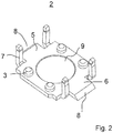
- the temperature controller comprises a preferably made of ceramic housing 16 (also called “base”), which rests on a plate-shaped support 2.
- Der Gezzause 2 ist mit dem Gezzause 2sky.
- the carrier 2 consists of a thermally conductive material, in particular of metal, preferably of aluminum. It comprises in each case a fastening arm 7 in each corner region of the carrier 2, which engages in each case on an outer recess of the housing 16 and holds both parts in position relative to one another.
- the housing has a recess.
- a bimetallic disc 21 rests on the upper side of the carrier 2 and is held in position at the edge by circumferentially arranged projections 3.
- the bimetallic disc takes two stable positions depending on the temperature (bistable bimetal snap-action disc). The two positions are determined by means of a mechanical scanning z. B. scanned in the form of a vertically disposed pin 22 and transmitted to a arranged in the upper region of the housing 16 contact spring 23.
- the pin 22 In a first stable position of the bimetallic disc 21, the pin 22 is pressed upward toward the contact spring 23 and thereby the electrical contact between the two connection contacts 4a, 4b is kept closed.
- the contact spring 23 is, for example, with the in FIG. 1B left connection contact 4a firmly connected.
- the in Fig. 1B right terminal contact 4b is held, for example, only by the conditional by the bimetallic disc 21 and the pin 22 contact force in the closed position.
- the pin 22 moves z. B. due to the bias of the contact spring 23 and gravity down.
- the electrical contact is thereby in the range of in Fig. 1B right terminal 4b open.
- the in Fig. 1 shown temperature controller is intended to directly on the surface of a (in Fig. 1 not shown) heating device or an intervening, connected to the heater mounting plate to be fixed by laser welding in thermal contact.
- the carrier 2 comprises at least one, preferably two, opposing regions 8, on which a laser welding is to be performed and which have undergone a special shape preparation for the laser welding.
- the carrier 2 preferably has a fastening tab 5, 6 respectively projecting on the outside on the housing 16, each having an edge formation specially provided for laser welding, which is provided at the in Fig. 1 illustrated embodiment preferably beveled, so chamfered.
- the chamfer angle is arbitrary, preferably it is in the range of 25 ° to 75 °.
- Fig. 3A shows the arrangement of the temperature controller 1 on top of a heater 15 after completed laser welding.
- the areas 8 for producing the laser welding in the longitudinal direction of the housing 16 which has the advantage that no weld spatter due to the closed housing in this area 16 in the interior of the temperature controller 1, so the bimetallic disc 21 out.
- the reference numeral 19, the respective elongated weld or weld bead is marked. It runs only along the area 8 of the carrier 2 specially prepared for the welding with respect to its shape.
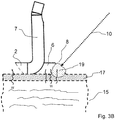
- Fig. 3B shows in an enlarged schematic representation of the homogeneous formation of the laser weld 19 in the region 8, ie in the region of the beveled end face of the plate-shaped support 2.
- the plate-shaped support 2 is flat on the outside of the wall 17 of the hot water containing heater 15, for example.
- a homogeneous, caused by the laser beam 10 melting area is generated both in the carrier 2 and in the wall 17 of the heater 15.
- the laser welding is carried out under protective gas. This can further reduce the risk of cracking.
- a laser with less energy than usual can be used.
- Conventional lasers for laser welding eg Nd: YAG laser or CO2 laser
- it is expedient to use less energy lasers for example so-called “green” lasers, due to the preparation of the support 2 for producing a welded joint without crack formation Laser "with a wavelength of only 532 nm.
- the energy input by the laser beam 10 is considerably lower, at the same time due to the contouring of the edge of the support 2 sets a laser weld 19 without cracking.
- so-called bifocal lasers can also be used.
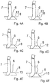
- FIGS. 4A-4F illustrated the frontal contouring of the area 8 may be formed differently for the laser welding.
- Fig. 4A shows an end edge bevel 12 of the edge of the fastening tab 6.
- Fig. 4B is in the edge bevel 12 in the area 8, an additional, the surface enlarging recess provided. This can for example also be used to accommodate a welding aid, for example in the form of a welding wire (see also Fig. 8D ).
- the edge bevel 12 can also be designed with a surface profiling in order to achieve an even better coupling of the laser beam and to largely avoid reflections thereof and resulting molten splashes.
- an edge rounding 13, z. B. as in Fig. 4E is shown, or an inwardly directed Kantenabrundung be provided in the form of a slightly concave curvature.
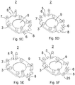
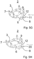
- the representations acc. Figs. 5A and 5B show in a perspective view in addition to the reduction in cross section by edge bevel 12 additionally made surface profiling 14, in particular surface roughening or surface corrugation or -schlitzung, provided for the laser welding area. 8
- the inclined surface is in the inner region of the respective fastening tab 5, 6.
- the recess 25 formed thereby can also be used to accommodate a welding additive.
- the material taper is provided in the region of the outer circumference of an opening 11, so that a connection can be made through an annular weld line in the region of the material taper of the opening 11.
- this embodiment can also be attached by means of a screw or a bolt due to the opening 11 if necessary.
- Laser welding can also be carried out if, instead of the opening 11, there is only one recess 20, as shown in FIG Fig. 5H is shown. Again, an edge bevel 12 is provided, along which an annular laser weld can be made with a laser of comparatively low energy. Again, the recess 20 can also be used to accommodate a filler metal.
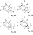
- FIGS. 6A to 6D illustrated embodiments of the individual carrier 2 have in the region of their attachment tabs 5, 6 only different structuring of the surface of the carrier without a tapered contouring.
- the embodiments of Figs. 6A-6C show across the entire width transverse grooves in different width and frequency or surface characteristics.
- the grooves of the embodiments according to FIGS. 6A and 6B are sharp-edged in the upper area, whereas in the embodiment according to Fig. 6C the areas located between the grooves are rounded upwards.
- Fig. 6D a variety of individual pyramidal shapes are provided. These refinements have the advantage that they are simple to realize in terms of manufacturing technology, and that a tapered edge contouring is omitted here. Nonetheless, the patterning of the surface makes it possible to perform an improved laser welding connection.
- the surfaces of the carrier 2 or of the respective fastening strap 5, 6 created by the surface profiling 14, as shown by way of example in FIG Fig. 6F is viewed from the top plane of the carrier viewed to an obliquely incident laser beam 10 out are oriented.
- the surface structuring thus has an effective at oblique incidence of the laser beam 10 preferred orientation.
- the particular configuration of the region 8 of the carrier 2 provided for the laser welding according to the above embodiments can be produced in a simple manner by an embossing process.
- Figs. 7A and 7B show a likewise encompassed by the present invention embodiment of a thermal switching device 1 in the form of a temperature controller with a round, cup-shaped carrier 2, which has circumferentially upstanding wall 24 for receiving the housing 16.
- the carrier 2 used here can be equipped to improve a welded joint with a region 8 in the form of an outer circumferential tapered contouring.
- this contouring surface structuring of the type described above can be provided.
- Fig. 7C shows an alternative embodiment of the round, cup-shaped carrier 2 with a provided only in circumferential sub-segments, the outer circumferential tapered contour or edge bevel 12th
- the carrier 2 (as not shown in the figures) have a constant thickness in the outer projecting region and also be provided here with a surface structuring of the type described above.
- Figs. 8A-8G show different embodiments of the present invention, in which the respective carrier 2, the fastening tab 5, 6 is combined with a welding filler 18 to a manageable assembly unit.
- a welding filler 18 is applied in a kind of foil or layer to the lower, planar surface of the carrier.
- the filler metal 18 extends around at least one corner of the carrier 2.
- the welding filler 18 extends around a front projection 26 around.
- the attachment of the welding consumables 18 is carried out by pressing. But can also be used strip-shaped welding consumables 18, which are glued, for example, on the carrier.
- the weld filler is aluminum with a relatively high silicon content.
- Fig. 9 shows the arrangement of a temperature controller 1 on the surface of a heater 15 with in the flush side area introduced by laser welding welds 19.
- One of the weld is frontally disposed on the temperature controller 1, the other two welds 19 are in the region of the side of the carrier 2.
Landscapes
- Engineering & Computer Science (AREA)
- Physics & Mathematics (AREA)
- Optics & Photonics (AREA)
- Mechanical Engineering (AREA)
- Plasma & Fusion (AREA)
- Laser Beam Processing (AREA)
- Fuses (AREA)
- Connection Of Plates (AREA)
Claims (23)
- Moyen de commutation thermique, en particulier régulateur de température, limiteur de température, contrôleur de température ou fusible thermique, pour la liaison en contact thermique avec un appareil de consommation comprenant un dispositif de chauffage, avec
un support (2) conducteur de la chaleur, de préférence en forme de plaque, présentant des pattes de fixation (5, 6), au moyen duquel le moyen de commutation (1) peut être mis en contact thermique avec l'appareil de consommation,
un élément fonctionnel réagissant à la température, de préférence un élément bimétallique (21) ou un élément fusible (24), destiné à garantir une fonction de commutation dépendant de la température du moyen de commutation (1), ainsi qu'avec
des contacts de raccordement (4a, 4b) pour le raccordement du moyen de commutation thermique (1) à une section de ligne électrique, dans lequel
le support (2) peut être assemblé dans la région de ses pattes de fixation (5, 6) à l'appareil de consommation se trouvant en contact thermique au moyen d'un soudage au laser,
caractérisé en ce que
les côtés inférieurs du support en forme de plaque (2) et de ses pattes de fixation (5, 6) sont de forme plane et sont situés dans le même plan, et
les pattes de fixation (5, 6) du support (2) présentent une zone spécialement préparée (8) pour l'injection d'un faisceau laser (10), de telle manière que la zone (8) comprenne une forme de contour et/ou une structuration de la surface des pattes de fixation (5, 6) du support (2) qui diminue la section transversale en direction du côté inférieur du support (2) . - Moyen de commutation thermique selon la revendication 1, caractérisé en ce que la zone (8) est un passage (11) ou un creux (20) prévu(e) dans la patte de fixation (5, 6).
- Moyen de commutation thermique selon au moins une des revendications précédentes, caractérisé en ce qu'il est prévu un biseautage d'arête (12) comme forme de contour dégressive.
- Moyen de commutation thermique selon la revendication 3, caractérisé en ce que la forme de contour dégressive est arrondie.
- Moyen de commutation thermique selon au moins une des revendications précédentes, caractérisé en ce qu'il est prévu un profilage de surface (14) comme structuration de la surface du support (2).
- Moyen de commutation thermique selon la revendication 5, caractérisé en ce que le profilage de surface (14) peut être orienté vers un faisceau arrivant en oblique.
- Moyen de commutation thermique selon la revendication 5 ou 6, caractérisé en ce qu'il est prévu comme profilage de surface (14) une structure de surface composée d'une multiplicité de sillons, de bosses, de pyramides, de dents, de creux, d'ondes, etc.
- Moyen de commutation thermique selon au moins une des revendications précédentes, caractérisé en ce que l'orientation des contacts de raccordement (4) dans un boîtier (16) du moyen de commutation et l'orientation de la ligne de jonction virtuelle de la zone respective (8) préparée pour le soudage au laser sont identiques.
- Moyen de commutation thermique selon au moins une des revendications précédentes, caractérisé en ce que le support (2) se compose d'aluminium ou d'un alliage d'aluminium.
- Moyen de commutation thermique selon au moins une des revendications précédentes, caractérisé en ce qu'un apport de soudage (18) est installé sur le support (2).
- Moyen de commutation thermique selon la revendication 10, caractérisé en ce que l'apport de soudage (18) est installé dans un renflement (19) sur le support (2) et/ou dans ou sur le support (2).
- Moyen de commutation thermique selon la revendication 10 ou 11, caractérisé en ce que l'apport de soudage (18) se trouve sur ou au moins dans la région de l'arête ou de la zone (8) du support (2).
- Moyen de commutation thermique selon au moins une des revendications 10 à 12, caractérisé en ce que l'apport de soudage (18) se présente sous forme de fil ou sous forme de couche.
- Moyen de commutation thermique selon au moins une des revendications 10 à 13, caractérisé en ce que l'apport de soudage (18) est positionné sur le côté frontal de l'arête du support (2).
- Moyen de chauffage pour un appareil de consommation comprenant
un dispositif de chauffage (15) avec un boîtier composé de préférence d'aluminium,
caractérisé par un moyen de commutation thermique selon au moins une des revendications précédentes,
dans lequel le moyen de commutation thermique est en contact thermique par son support (2) avec le boîtier du dispositif de chauffage (15) et
le support du moyen de commutation thermique est fixé au moyen d'un assemblage soudé au laser au boîtier du dispositif de chauffage (15) ou à une plaque de fixation se trouvant entre eux. - Agencement de chauffage selon la revendication 15,
caractérisé en ce que la surface du dispositif de chauffage (15) ou de la plaque de fixation se trouvant entre eux déborde sur le support (2) et il se forme à la transition du support (2) à la surface du dispositif de chauffage (15) ou de la plaque de fixation se trouvant entre eux un point de soudure, sur lequel il est prévu au moins un cordon de soudure au laser (19). - Agencement de chauffage selon la revendication 15,
caractérisé en ce que l'arête extérieure du support (2) du moyen de commutation thermique (1) et la face latérale du dispositif de chauffage (15) forment une transition alignée à plat et il est prévu au moins un cordon de soudure au laser (19) au point de soudure de la transition entre le support (2) du moyen de commutation thermique (1) et la surface du dispositif de chauffage (15). - Procédé de montage d'un moyen de commutation thermique, caractérisé en ce que l'on utilise un moyen de commutation thermique selon au moins une des revendications 1 à 14 sur la surface d'un dispositif de chauffage d'un appareil de consommation ou sur une plaque de fixation se trouvant entre eux assemblée au dispositif de chauffage au moyen d'un soudage au laser.
- Procédé selon la revendication 18, caractérisé en ce que le faisceau laser atteint essentiellement perpendiculairement la zone (8) avec la forme de contour dégressive.
- Procédé selon la revendication 18 ou 19,
caractérisé en ce que l'on utilise pour la production du faisceau laser un laser ayant une longueur d'onde comprise dans la plage de 400 à 1200 nm, de préférence de 400 à 750 nm. - Procédé selon la revendication 20, caractérisé en ce qu'un préchauffage ou une pré-initialisation de la zone préparée pour le soudage a lieu au moyen d'un laser ayant une longueur d'onde comprise dans la plage de 400 à 1200 nm, de préférence de 400 à 750 nm.
- Procédé selon au moins une des revendications 18 à 21, caractérisé en ce que l'on utilise un laser bifocal pour la production du faisceau laser.
- Procédé selon au moins une des revendications 18 à 22, caractérisé en ce que l'on effectue le soudage en utilisant un apport de soudage.
Priority Applications (3)
| Application Number | Priority Date | Filing Date | Title |
|---|---|---|---|
| EP17176633.0A EP3255647B1 (fr) | 2013-12-06 | 2014-12-05 | Support thermoconducteur, de préférence en forme de plaque et assemblage soudé au laser |
| PL14812169T PL3050070T3 (pl) | 2013-12-06 | 2014-12-05 | Termiczny wyłącznik, układ grzewczy oraz sposób montażu termicznego wyłącznika na urządzeniu grzejnym |
| HRP20180622TT HRP20180622T1 (hr) | 2013-12-06 | 2014-12-05 | Uređaj za toplinsko prekidanje, uređaj za grijanje i postupak ugradnje uređaja za toplinsko prekidanje na uređaj za grijanje |
Applications Claiming Priority (2)
| Application Number | Priority Date | Filing Date | Title |
|---|---|---|---|
| DE102013113650.8A DE102013113650A1 (de) | 2013-12-06 | 2013-12-06 | Thermische Schalteinrichtung, Heizungsanordnung sowie Verfahren zur Montage einer thermischen Schalteinrichtung an einer Heizungseinrichtung |
| PCT/EP2014/076688 WO2015082671A2 (fr) | 2013-12-06 | 2014-12-05 | Moyen de commutation thermique, dispositif de chauffage et procédé de montage d'un moyen de commutation thermique sur un moyen de chauffage |
Related Child Applications (2)
| Application Number | Title | Priority Date | Filing Date |
|---|---|---|---|
| EP17176633.0A Division EP3255647B1 (fr) | 2013-12-06 | 2014-12-05 | Support thermoconducteur, de préférence en forme de plaque et assemblage soudé au laser |
| EP17176633.0A Division-Into EP3255647B1 (fr) | 2013-12-06 | 2014-12-05 | Support thermoconducteur, de préférence en forme de plaque et assemblage soudé au laser |
Publications (2)
| Publication Number | Publication Date |
|---|---|
| EP3050070A2 EP3050070A2 (fr) | 2016-08-03 |
| EP3050070B1 true EP3050070B1 (fr) | 2018-02-28 |
Family
ID=52101300
Family Applications (2)
| Application Number | Title | Priority Date | Filing Date |
|---|---|---|---|
| EP17176633.0A Active EP3255647B1 (fr) | 2013-12-06 | 2014-12-05 | Support thermoconducteur, de préférence en forme de plaque et assemblage soudé au laser |
| EP14812169.2A Active EP3050070B1 (fr) | 2013-12-06 | 2014-12-05 | Moyen de commutation thermique, dispositif de chauffage et procédé de montage d'un moyen de commutation thermique sur un moyen de chauffage |
Family Applications Before (1)
| Application Number | Title | Priority Date | Filing Date |
|---|---|---|---|
| EP17176633.0A Active EP3255647B1 (fr) | 2013-12-06 | 2014-12-05 | Support thermoconducteur, de préférence en forme de plaque et assemblage soudé au laser |
Country Status (8)
| Country | Link |
|---|---|
| EP (2) | EP3255647B1 (fr) |
| CN (2) | CN105793949B (fr) |
| DE (1) | DE102013113650A1 (fr) |
| ES (1) | ES2670987T3 (fr) |
| HR (1) | HRP20180622T1 (fr) |
| HU (1) | HUE037686T2 (fr) |
| PL (1) | PL3050070T3 (fr) |
| WO (1) | WO2015082671A2 (fr) |
Cited By (1)
| Publication number | Priority date | Publication date | Assignee | Title |
|---|---|---|---|---|
| EP3553413B1 (fr) * | 2014-06-24 | 2025-12-17 | Bleckmann GmbH & Co. KG | Système de chauffage |
Citations (1)
| Publication number | Priority date | Publication date | Assignee | Title |
|---|---|---|---|---|
| DE19753103A1 (de) * | 1997-11-29 | 1999-06-02 | Volkswagen Ag | Verfahren zum Verschweißen zweier plattenförmiger Werkstücke |
Family Cites Families (17)
| Publication number | Priority date | Publication date | Assignee | Title |
|---|---|---|---|---|
| JPS63130290A (ja) * | 1986-11-20 | 1988-06-02 | Matsushita Electric Works Ltd | エネルギビ−ムによる溶接方法 |
| DE3909471C2 (de) * | 1988-06-21 | 1993-10-07 | Fraunhofer Ges Forschung | Überlappstoß zum Schweißen von beschichteten Werkstücken mittels Laserstrahlung |
| DE19706316C2 (de) | 1997-02-18 | 1999-10-21 | Inter Control Koehler Hermann | Thermische Schalteinrichtung, sowie Verfahren zu dessen Herstellung |
| GB2333901B (en) * | 1997-09-25 | 2000-06-14 | Otter Controls Ltd | Improvements relating to electrically heated water boiling vessels |
| EP1249851B1 (fr) * | 1998-04-21 | 2008-11-26 | Otter Controls Limited | Améliorations relatives a la commande d'éléments chauffants électriques |
| AU3617099A (en) * | 1998-04-21 | 1999-11-08 | Otter Controls Limited | Improvements relating to the control of electric heating elements |
| DE19852883C1 (de) | 1998-11-17 | 2000-01-27 | Braun Gmbh | Durchlauferhitzer für ein wassererhitzendes Haushaltsgerät |
| US7138598B2 (en) * | 2003-12-01 | 2006-11-21 | General Motors Corporation | Apparatus and method for accommodating part mismatch during joining |
| DE102004009651B4 (de) * | 2004-02-27 | 2008-10-09 | BLZ Bayerisches Laserzentrum Gemeinnützige Forschungsgesellschaft mbH | Verfahren zum Schweißen artungleicher metallischer Fügepartner, insbesondere von Aluminium-Kupfer-Verbindungsstellen |
| DE102004055083B4 (de) * | 2004-11-15 | 2008-01-17 | Trw Automotive Electronics & Components Gmbh & Co. Kg | Schweißteil für das Verschweißen mittels einer Kehlnaht und elektrische Baueinheit |
| CN2750454Y (zh) * | 2004-11-16 | 2006-01-04 | 黄明伟 | 温控器 |
| DE202005019880U1 (de) | 2005-12-20 | 2006-02-16 | Inter Control Hermann Köhler Elektrik GmbH & Co. KG | Temperaturregler und Kombination von Temperaturregler und Temperatursicherung |
| WO2010131298A1 (fr) * | 2009-05-15 | 2010-11-18 | トヨタ自動車株式会社 | Procédé de soudage laser et procédé de fabrication d'une batterie le comprenant |
| CN102297506B (zh) * | 2011-08-12 | 2013-04-24 | 杭州热威机电有限公司 | 和泵相结合的加热器 |
| CN103165837B (zh) * | 2011-12-16 | 2017-12-22 | 株式会社杰士汤浅国际 | 蓄电装置及其制造方法以及该蓄电装置中使用的汇流条 |
| US9553294B2 (en) * | 2011-12-16 | 2017-01-24 | Gs Yuasa International Ltd. | Electric storage device, manufacturing method of electric storage device, and bus bar used for electric storage device |
| CN202650980U (zh) * | 2012-06-07 | 2013-01-02 | 厦门升明电子有限公司 | 多功能温控器 |
-
2013
- 2013-12-06 DE DE102013113650.8A patent/DE102013113650A1/de not_active Withdrawn
-
2014
- 2014-12-05 EP EP17176633.0A patent/EP3255647B1/fr active Active
- 2014-12-05 PL PL14812169T patent/PL3050070T3/pl unknown
- 2014-12-05 CN CN201480065831.5A patent/CN105793949B/zh active Active
- 2014-12-05 EP EP14812169.2A patent/EP3050070B1/fr active Active
- 2014-12-05 HR HRP20180622TT patent/HRP20180622T1/hr unknown
- 2014-12-05 HU HUE14812169A patent/HUE037686T2/hu unknown
- 2014-12-05 ES ES14812169.2T patent/ES2670987T3/es active Active
- 2014-12-05 CN CN201711101210.XA patent/CN107895671B/zh active Active
- 2014-12-05 WO PCT/EP2014/076688 patent/WO2015082671A2/fr not_active Ceased
Patent Citations (1)
| Publication number | Priority date | Publication date | Assignee | Title |
|---|---|---|---|---|
| DE19753103A1 (de) * | 1997-11-29 | 1999-06-02 | Volkswagen Ag | Verfahren zum Verschweißen zweier plattenförmiger Werkstücke |
Cited By (1)
| Publication number | Priority date | Publication date | Assignee | Title |
|---|---|---|---|---|
| EP3553413B1 (fr) * | 2014-06-24 | 2025-12-17 | Bleckmann GmbH & Co. KG | Système de chauffage |
Also Published As
| Publication number | Publication date |
|---|---|
| CN105793949A (zh) | 2016-07-20 |
| EP3255647B1 (fr) | 2019-10-30 |
| WO2015082671A2 (fr) | 2015-06-11 |
| HUE037686T2 (hu) | 2018-09-28 |
| HRP20180622T1 (hr) | 2018-06-01 |
| PL3050070T3 (pl) | 2018-08-31 |
| WO2015082671A3 (fr) | 2015-07-30 |
| DE102013113650A1 (de) | 2015-06-11 |
| EP3050070A2 (fr) | 2016-08-03 |
| CN105793949B (zh) | 2018-09-07 |
| CN107895671A (zh) | 2018-04-10 |
| ES2670987T3 (es) | 2018-06-04 |
| CN107895671B (zh) | 2020-05-26 |
| EP3255647A1 (fr) | 2017-12-13 |
Similar Documents
| Publication | Publication Date | Title |
|---|---|---|
| DE19641856B4 (de) | Zündkerze für einen Verbrennungsmotor | |
| EP3215310B1 (fr) | Procédé de traitement d'un premier composant et d'un second composant par soudage laser et dispositif associé | |
| EP3017509B1 (fr) | Procédé de raccordement d'un conducteur électrique à un élément de contact électrique | |
| DE202012013150U1 (de) | Scheibe mit einem elektrischen Anschlusselement | |
| WO2017194261A1 (fr) | Panne à souder pour un fer à souder | |
| EP2500161B1 (fr) | Dispositif de connexion de deux composants en matière plastique à l'aide d'un faisceau laser | |
| EP3030372B1 (fr) | Procédé de fabrication d'une liaison soudée | |
| EP2282320A1 (fr) | Disque bimétallique embouti | |
| DE10002703A1 (de) | Verfahren zum Herstellen einer elektrisch leitenden Verbindung mittels Laserstrahlung | |
| WO2016083557A1 (fr) | Élément de connexion, dispositif collecteur de courant et procédé de fabrication correspondant | |
| EP3050070B1 (fr) | Moyen de commutation thermique, dispositif de chauffage et procédé de montage d'un moyen de commutation thermique sur un moyen de chauffage | |
| EP2548242B1 (fr) | Mise en contact de batterie au moyen d'éléments de connexion binaires adaptés | |
| WO2019202117A1 (fr) | Module d'éléments d'accumulateur et procédé de mise en contact des éléments d'accumulateur | |
| WO2006005291A1 (fr) | Procede de liaison d'au moins un conducteur a un element de contact | |
| WO2009156505A1 (fr) | Procédé et dispositif pour connecter des composants au moyen d'un rayonnement laser | |
| DE102015103003B3 (de) | Elektrisches Kontaktelement | |
| EP0688526A1 (fr) | Récipient de cuisson en forme d'un pot | |
| EP2922373B1 (fr) | Procédé de raccordement de deux composants conducteurs d'électricité au moyen d'un rayon laser et composite de composant | |
| EP4255664B1 (fr) | Procédé de revêtement par film à l'aide d'un laser | |
| EP0916149B1 (fr) | Commutateur electrique et son procede de fabrication | |
| DE3604021A1 (de) | Thermostat | |
| EP4168204B1 (fr) | Procédé de réalisation d'une connexion sans espace par adhérence | |
| DE102018209975A1 (de) | Verfahren zum Verschweißen zweier Bauteile, Bauteileverbund und Verwendung des Verfahrens | |
| DE3621878A1 (de) | Kappen- und traegeranordnung fuer einen thermostatschalter sowie verfahren zu ihrer herstellung | |
| DE102016117220B3 (de) | Elektrische Verbindungsanordnung mit Abreißsicherungsfunktion |
Legal Events
| Date | Code | Title | Description |
|---|---|---|---|
| PUAI | Public reference made under article 153(3) epc to a published international application that has entered the european phase |
Free format text: ORIGINAL CODE: 0009012 |
|
| 17P | Request for examination filed |
Effective date: 20160315 |
|
| AK | Designated contracting states |
Kind code of ref document: A2 Designated state(s): AL AT BE BG CH CY CZ DE DK EE ES FI FR GB GR HR HU IE IS IT LI LT LU LV MC MK MT NL NO PL PT RO RS SE SI SK SM TR |
|
| AX | Request for extension of the european patent |
Extension state: BA ME |
|
| DAX | Request for extension of the european patent (deleted) | ||
| GRAP | Despatch of communication of intention to grant a patent |
Free format text: ORIGINAL CODE: EPIDOSNIGR1 |
|
| RIC1 | Information provided on ipc code assigned before grant |
Ipc: H01H 37/04 20060101AFI20170404BHEP Ipc: B23K 26/20 20140101ALI20170404BHEP Ipc: B23K 26/242 20140101ALN20170404BHEP Ipc: B23K 101/36 20060101ALN20170404BHEP Ipc: H01H 37/00 20060101ALN20170404BHEP Ipc: B23K 33/00 20060101ALN20170404BHEP |
|
| RIC1 | Information provided on ipc code assigned before grant |
Ipc: B23K 33/00 20060101ALN20170411BHEP Ipc: H01H 37/04 20060101AFI20170411BHEP Ipc: B23K 26/20 20140101ALI20170411BHEP Ipc: H01H 37/00 20060101ALN20170411BHEP Ipc: B23K 101/36 20060101ALN20170411BHEP Ipc: B23K 26/242 20140101ALN20170411BHEP |
|
| INTG | Intention to grant announced |
Effective date: 20170502 |
|
| GRAS | Grant fee paid |
Free format text: ORIGINAL CODE: EPIDOSNIGR3 |
|
| GRAJ | Information related to disapproval of communication of intention to grant by the applicant or resumption of examination proceedings by the epo deleted |
Free format text: ORIGINAL CODE: EPIDOSDIGR1 |
|
| GRAL | Information related to payment of fee for publishing/printing deleted |
Free format text: ORIGINAL CODE: EPIDOSDIGR3 |
|
| INTC | Intention to grant announced (deleted) | ||
| RIC1 | Information provided on ipc code assigned before grant |
Ipc: B23K 26/242 20140101ALN20170817BHEP Ipc: B23K 33/00 20060101ALN20170817BHEP Ipc: B23K 26/20 20140101ALI20170817BHEP Ipc: H01H 37/00 20060101ALN20170817BHEP Ipc: H01H 37/04 20060101AFI20170817BHEP Ipc: B23K 101/36 20060101ALN20170817BHEP |
|
| GRAR | Information related to intention to grant a patent recorded |
Free format text: ORIGINAL CODE: EPIDOSNIGR71 |
|
| TPAC | Observations filed by third parties |
Free format text: ORIGINAL CODE: EPIDOSNTIPA |
|
| INTG | Intention to grant announced |
Effective date: 20171023 |
|
| GRAA | (expected) grant |
Free format text: ORIGINAL CODE: 0009210 |
|
| AK | Designated contracting states |
Kind code of ref document: B1 Designated state(s): AL AT BE BG CH CY CZ DE DK EE ES FI FR GB GR HR HU IE IS IT LI LT LU LV MC MK MT NL NO PL PT RO RS SE SI SK SM TR |
|
| REG | Reference to a national code |
Ref country code: GB Ref legal event code: FG4D Free format text: NOT ENGLISH Ref country code: CH Ref legal event code: EP |
|
| REG | Reference to a national code |
Ref country code: AT Ref legal event code: REF Ref document number: 974993 Country of ref document: AT Kind code of ref document: T Effective date: 20180315 |
|
| REG | Reference to a national code |
Ref country code: IE Ref legal event code: FG4D Free format text: LANGUAGE OF EP DOCUMENT: GERMAN |
|
| REG | Reference to a national code |
Ref country code: CH Ref legal event code: NV Representative=s name: PATENTANWAELTE SCHAAD, BALASS, MENZL AND PARTN, CH |
|
| REG | Reference to a national code |
Ref country code: DE Ref legal event code: R096 Ref document number: 502014007474 Country of ref document: DE |
|
| REG | Reference to a national code |
Ref country code: RO Ref legal event code: EPE |
|
| REG | Reference to a national code |
Ref country code: HR Ref legal event code: TUEP Ref document number: P20180622 Country of ref document: HR |
|
| REG | Reference to a national code |
Ref country code: SE Ref legal event code: TRGR |
|
| REG | Reference to a national code |
Ref country code: HR Ref legal event code: T1PR Ref document number: P20180622 Country of ref document: HR |
|
| REG | Reference to a national code |
Ref country code: ES Ref legal event code: FG2A Ref document number: 2670987 Country of ref document: ES Kind code of ref document: T3 Effective date: 20180604 |
|
| REG | Reference to a national code |
Ref country code: NL Ref legal event code: MP Effective date: 20180228 |
|
| REG | Reference to a national code |
Ref country code: LT Ref legal event code: MG4D |
|
| PG25 | Lapsed in a contracting state [announced via postgrant information from national office to epo] |
Ref country code: FI Free format text: LAPSE BECAUSE OF FAILURE TO SUBMIT A TRANSLATION OF THE DESCRIPTION OR TO PAY THE FEE WITHIN THE PRESCRIBED TIME-LIMIT Effective date: 20180228 Ref country code: LT Free format text: LAPSE BECAUSE OF FAILURE TO SUBMIT A TRANSLATION OF THE DESCRIPTION OR TO PAY THE FEE WITHIN THE PRESCRIBED TIME-LIMIT Effective date: 20180228 Ref country code: NL Free format text: LAPSE BECAUSE OF FAILURE TO SUBMIT A TRANSLATION OF THE DESCRIPTION OR TO PAY THE FEE WITHIN THE PRESCRIBED TIME-LIMIT Effective date: 20180228 Ref country code: CY Free format text: LAPSE BECAUSE OF FAILURE TO SUBMIT A TRANSLATION OF THE DESCRIPTION OR TO PAY THE FEE WITHIN THE PRESCRIBED TIME-LIMIT Effective date: 20180228 Ref country code: NO Free format text: LAPSE BECAUSE OF FAILURE TO SUBMIT A TRANSLATION OF THE DESCRIPTION OR TO PAY THE FEE WITHIN THE PRESCRIBED TIME-LIMIT Effective date: 20180528 |
|
| PG25 | Lapsed in a contracting state [announced via postgrant information from national office to epo] |
Ref country code: BG Free format text: LAPSE BECAUSE OF FAILURE TO SUBMIT A TRANSLATION OF THE DESCRIPTION OR TO PAY THE FEE WITHIN THE PRESCRIBED TIME-LIMIT Effective date: 20180528 Ref country code: GR Free format text: LAPSE BECAUSE OF FAILURE TO SUBMIT A TRANSLATION OF THE DESCRIPTION OR TO PAY THE FEE WITHIN THE PRESCRIBED TIME-LIMIT Effective date: 20180529 Ref country code: LV Free format text: LAPSE BECAUSE OF FAILURE TO SUBMIT A TRANSLATION OF THE DESCRIPTION OR TO PAY THE FEE WITHIN THE PRESCRIBED TIME-LIMIT Effective date: 20180228 Ref country code: RS Free format text: LAPSE BECAUSE OF FAILURE TO SUBMIT A TRANSLATION OF THE DESCRIPTION OR TO PAY THE FEE WITHIN THE PRESCRIBED TIME-LIMIT Effective date: 20180228 |
|
| PG25 | Lapsed in a contracting state [announced via postgrant information from national office to epo] |
Ref country code: MT Free format text: LAPSE BECAUSE OF FAILURE TO SUBMIT A TRANSLATION OF THE DESCRIPTION OR TO PAY THE FEE WITHIN THE PRESCRIBED TIME-LIMIT Effective date: 20180228 |
|
| REG | Reference to a national code |
Ref country code: HU Ref legal event code: AG4A Ref document number: E037686 Country of ref document: HU |
|
| PG25 | Lapsed in a contracting state [announced via postgrant information from national office to epo] |
Ref country code: EE Free format text: LAPSE BECAUSE OF FAILURE TO SUBMIT A TRANSLATION OF THE DESCRIPTION OR TO PAY THE FEE WITHIN THE PRESCRIBED TIME-LIMIT Effective date: 20180228 Ref country code: AL Free format text: LAPSE BECAUSE OF FAILURE TO SUBMIT A TRANSLATION OF THE DESCRIPTION OR TO PAY THE FEE WITHIN THE PRESCRIBED TIME-LIMIT Effective date: 20180228 |
|
| REG | Reference to a national code |
Ref country code: DE Ref legal event code: R097 Ref document number: 502014007474 Country of ref document: DE |
|
| PG25 | Lapsed in a contracting state [announced via postgrant information from national office to epo] |
Ref country code: DK Free format text: LAPSE BECAUSE OF FAILURE TO SUBMIT A TRANSLATION OF THE DESCRIPTION OR TO PAY THE FEE WITHIN THE PRESCRIBED TIME-LIMIT Effective date: 20180228 Ref country code: SM Free format text: LAPSE BECAUSE OF FAILURE TO SUBMIT A TRANSLATION OF THE DESCRIPTION OR TO PAY THE FEE WITHIN THE PRESCRIBED TIME-LIMIT Effective date: 20180228 Ref country code: SK Free format text: LAPSE BECAUSE OF FAILURE TO SUBMIT A TRANSLATION OF THE DESCRIPTION OR TO PAY THE FEE WITHIN THE PRESCRIBED TIME-LIMIT Effective date: 20180228 |
|
| REG | Reference to a national code |
Ref country code: HR Ref legal event code: ODRP Ref document number: P20180622 Country of ref document: HR Payment date: 20181127 Year of fee payment: 5 |
|
| PLBE | No opposition filed within time limit |
Free format text: ORIGINAL CODE: 0009261 |
|
| STAA | Information on the status of an ep patent application or granted ep patent |
Free format text: STATUS: NO OPPOSITION FILED WITHIN TIME LIMIT |
|
| 26N | No opposition filed |
Effective date: 20181129 |
|
| PG25 | Lapsed in a contracting state [announced via postgrant information from national office to epo] |
Ref country code: SI Free format text: LAPSE BECAUSE OF FAILURE TO SUBMIT A TRANSLATION OF THE DESCRIPTION OR TO PAY THE FEE WITHIN THE PRESCRIBED TIME-LIMIT Effective date: 20180228 |
|
| REG | Reference to a national code |
Ref country code: HR Ref legal event code: ODRP Ref document number: P20180622 Country of ref document: HR Payment date: 20191126 Year of fee payment: 6 |
|
| PGFP | Annual fee paid to national office [announced via postgrant information from national office to epo] |
Ref country code: MC Payment date: 20191216 Year of fee payment: 6 Ref country code: IE Payment date: 20191217 Year of fee payment: 6 |
|
| PGFP | Annual fee paid to national office [announced via postgrant information from national office to epo] |
Ref country code: HR Payment date: 20191126 Year of fee payment: 6 Ref country code: BE Payment date: 20191217 Year of fee payment: 6 Ref country code: LU Payment date: 20191217 Year of fee payment: 6 |
|
| PG25 | Lapsed in a contracting state [announced via postgrant information from national office to epo] |
Ref country code: PT Free format text: LAPSE BECAUSE OF FAILURE TO SUBMIT A TRANSLATION OF THE DESCRIPTION OR TO PAY THE FEE WITHIN THE PRESCRIBED TIME-LIMIT Effective date: 20180228 |
|
| PG25 | Lapsed in a contracting state [announced via postgrant information from national office to epo] |
Ref country code: MK Free format text: LAPSE BECAUSE OF NON-PAYMENT OF DUE FEES Effective date: 20180228 |
|
| PG25 | Lapsed in a contracting state [announced via postgrant information from national office to epo] |
Ref country code: IS Free format text: LAPSE BECAUSE OF FAILURE TO SUBMIT A TRANSLATION OF THE DESCRIPTION OR TO PAY THE FEE WITHIN THE PRESCRIBED TIME-LIMIT Effective date: 20180628 |
|
| REG | Reference to a national code |
Ref country code: HR Ref legal event code: PBON Ref document number: P20180622 Country of ref document: HR Effective date: 20201205 |
|
| PG25 | Lapsed in a contracting state [announced via postgrant information from national office to epo] |
Ref country code: MC Free format text: LAPSE BECAUSE OF NON-PAYMENT OF DUE FEES Effective date: 20210104 |
|
| REG | Reference to a national code |
Ref country code: BE Ref legal event code: MM Effective date: 20201231 |
|
| PG25 | Lapsed in a contracting state [announced via postgrant information from national office to epo] |
Ref country code: LU Free format text: LAPSE BECAUSE OF NON-PAYMENT OF DUE FEES Effective date: 20201205 Ref country code: IE Free format text: LAPSE BECAUSE OF NON-PAYMENT OF DUE FEES Effective date: 20201205 Ref country code: HR Free format text: LAPSE BECAUSE OF NON-PAYMENT OF DUE FEES Effective date: 20201205 |
|
| PG25 | Lapsed in a contracting state [announced via postgrant information from national office to epo] |
Ref country code: BE Free format text: LAPSE BECAUSE OF NON-PAYMENT OF DUE FEES Effective date: 20201231 |
|
| P01 | Opt-out of the competence of the unified patent court (upc) registered |
Effective date: 20230508 |
|
| REG | Reference to a national code |
Ref country code: DE Ref legal event code: R082 Ref document number: 502014007474 Country of ref document: DE Representative=s name: 4IP GLEIMPETRI PATENT- UND RECHTSANWALTSPARTNE, DE |
|
| REG | Reference to a national code |
Ref country code: CH Ref legal event code: U11 Free format text: ST27 STATUS EVENT CODE: U-0-0-U10-U11 (AS PROVIDED BY THE NATIONAL OFFICE) Effective date: 20260101 |
|
| PGFP | Annual fee paid to national office [announced via postgrant information from national office to epo] |
Ref country code: DE Payment date: 20251002 Year of fee payment: 12 |
|
| PGFP | Annual fee paid to national office [announced via postgrant information from national office to epo] |
Ref country code: GB Payment date: 20251218 Year of fee payment: 12 |
|
| PGFP | Annual fee paid to national office [announced via postgrant information from national office to epo] |
Ref country code: AT Payment date: 20251215 Year of fee payment: 12 |
|
| PGFP | Annual fee paid to national office [announced via postgrant information from national office to epo] |
Ref country code: HU Payment date: 20251202 Year of fee payment: 12 Ref country code: FR Payment date: 20251217 Year of fee payment: 12 |
|
| PGFP | Annual fee paid to national office [announced via postgrant information from national office to epo] |
Ref country code: TR Payment date: 20251128 Year of fee payment: 12 |
|
| PGFP | Annual fee paid to national office [announced via postgrant information from national office to epo] |
Ref country code: SE Payment date: 20251217 Year of fee payment: 12 |
|
| PGFP | Annual fee paid to national office [announced via postgrant information from national office to epo] |
Ref country code: CZ Payment date: 20251124 Year of fee payment: 12 |
|
| PGFP | Annual fee paid to national office [announced via postgrant information from national office to epo] |
Ref country code: PL Payment date: 20251121 Year of fee payment: 12 |
|
| PGFP | Annual fee paid to national office [announced via postgrant information from national office to epo] |
Ref country code: RO Payment date: 20251127 Year of fee payment: 12 |
|
| PGFP | Annual fee paid to national office [announced via postgrant information from national office to epo] |
Ref country code: ES Payment date: 20260119 Year of fee payment: 12 |
|
| PGFP | Annual fee paid to national office [announced via postgrant information from national office to epo] |
Ref country code: IT Payment date: 20251231 Year of fee payment: 12 |
|
| PGFP | Annual fee paid to national office [announced via postgrant information from national office to epo] |
Ref country code: CH Payment date: 20260101 Year of fee payment: 12 |