EP3050427B1 - Jardinière - Google Patents
Jardinière Download PDFInfo
- Publication number
- EP3050427B1 EP3050427B1 EP15003535.0A EP15003535A EP3050427B1 EP 3050427 B1 EP3050427 B1 EP 3050427B1 EP 15003535 A EP15003535 A EP 15003535A EP 3050427 B1 EP3050427 B1 EP 3050427B1
- Authority
- EP
- European Patent Office
- Prior art keywords
- tube
- hollow body
- plant
- container according
- plant container
- Prior art date
- Legal status (The legal status is an assumption and is not a legal conclusion. Google has not performed a legal analysis and makes no representation as to the accuracy of the status listed.)
- Active
Links
- 239000000758 substrate Substances 0.000 claims description 38
- 239000007788 liquid Substances 0.000 claims description 20
- XLYOFNOQVPJJNP-UHFFFAOYSA-N water Substances O XLYOFNOQVPJJNP-UHFFFAOYSA-N 0.000 claims description 11
- 239000002689 soil Substances 0.000 claims description 10
- 238000005520 cutting process Methods 0.000 claims description 8
- 239000011148 porous material Substances 0.000 claims description 8
- 238000001746 injection moulding Methods 0.000 claims description 4
- 239000000463 material Substances 0.000 claims description 3
- 239000002361 compost Substances 0.000 claims description 2
- 239000002699 waste material Substances 0.000 claims description 2
- 239000011796 hollow space material Substances 0.000 claims 1
- 241000196324 Embryophyta Species 0.000 description 76
- 238000003973 irrigation Methods 0.000 description 11
- 230000002262 irrigation Effects 0.000 description 11
- 238000004519 manufacturing process Methods 0.000 description 5
- 238000010276 construction Methods 0.000 description 3
- 235000013162 Cocos nucifera Nutrition 0.000 description 2
- 244000060011 Cocos nucifera Species 0.000 description 2
- 239000000919 ceramic Substances 0.000 description 2
- 238000009264 composting Methods 0.000 description 2
- 230000001419 dependent effect Effects 0.000 description 2
- 239000003337 fertilizer Substances 0.000 description 2
- 230000012010 growth Effects 0.000 description 2
- 238000003780 insertion Methods 0.000 description 2
- 230000037431 insertion Effects 0.000 description 2
- 235000015097 nutrients Nutrition 0.000 description 2
- 239000010908 plant waste Substances 0.000 description 2
- 238000005406 washing Methods 0.000 description 2
- WGRYZUZDVLBGDM-UHFFFAOYSA-N C=CCC(C1)C2C1CCC2 Chemical compound C=CCC(C1)C2C1CCC2 WGRYZUZDVLBGDM-UHFFFAOYSA-N 0.000 description 1
- HDLMKRICOHXMJL-UHFFFAOYSA-N CC(C1)C2C1C(C1)=C1CC2 Chemical compound CC(C1)C2C1C(C1)=C1CC2 HDLMKRICOHXMJL-UHFFFAOYSA-N 0.000 description 1
- 235000002767 Daucus carota Nutrition 0.000 description 1
- 244000000626 Daucus carota Species 0.000 description 1
- 238000007599 discharging Methods 0.000 description 1
- 230000000694 effects Effects 0.000 description 1
- 239000012530 fluid Substances 0.000 description 1
- 230000035784 germination Effects 0.000 description 1
- 239000011521 glass Substances 0.000 description 1
- 238000002955 isolation Methods 0.000 description 1
- 230000008635 plant growth Effects 0.000 description 1
- 230000008092 positive effect Effects 0.000 description 1
- 238000004382 potting Methods 0.000 description 1
- 230000005855 radiation Effects 0.000 description 1
- 230000001105 regulatory effect Effects 0.000 description 1
- 230000000452 restraining effect Effects 0.000 description 1
- 230000000630 rising effect Effects 0.000 description 1
- 238000003860 storage Methods 0.000 description 1
- 239000000126 substance Substances 0.000 description 1
- 238000011144 upstream manufacturing Methods 0.000 description 1
- 238000010792 warming Methods 0.000 description 1
Images








Classifications
-
- A—HUMAN NECESSITIES
- A01—AGRICULTURE; FORESTRY; ANIMAL HUSBANDRY; HUNTING; TRAPPING; FISHING
- A01G—HORTICULTURE; CULTIVATION OF VEGETABLES, FLOWERS, RICE, FRUIT, VINES, HOPS OR SEAWEED; FORESTRY; WATERING
- A01G9/00—Cultivation in receptacles, forcing-frames or greenhouses; Edging for beds, lawn or the like
- A01G9/02—Receptacles, e.g. flower-pots or boxes; Glasses for cultivating flowers
- A01G9/022—Pots for vertical horticulture
- A01G9/025—Containers and elements for greening walls
-
- A—HUMAN NECESSITIES
- A01—AGRICULTURE; FORESTRY; ANIMAL HUSBANDRY; HUNTING; TRAPPING; FISHING
- A01G—HORTICULTURE; CULTIVATION OF VEGETABLES, FLOWERS, RICE, FRUIT, VINES, HOPS OR SEAWEED; FORESTRY; WATERING
- A01G31/00—Soilless cultivation, e.g. hydroponics
- A01G31/02—Special apparatus therefor
-
- A—HUMAN NECESSITIES
- A01—AGRICULTURE; FORESTRY; ANIMAL HUSBANDRY; HUNTING; TRAPPING; FISHING
- A01G—HORTICULTURE; CULTIVATION OF VEGETABLES, FLOWERS, RICE, FRUIT, VINES, HOPS OR SEAWEED; FORESTRY; WATERING
- A01G31/00—Soilless cultivation, e.g. hydroponics
- A01G31/02—Special apparatus therefor
- A01G31/06—Hydroponic culture on racks or in stacked containers
-
- A—HUMAN NECESSITIES
- A01—AGRICULTURE; FORESTRY; ANIMAL HUSBANDRY; HUNTING; TRAPPING; FISHING
- A01G—HORTICULTURE; CULTIVATION OF VEGETABLES, FLOWERS, RICE, FRUIT, VINES, HOPS OR SEAWEED; FORESTRY; WATERING
- A01G9/00—Cultivation in receptacles, forcing-frames or greenhouses; Edging for beds, lawn or the like
- A01G9/02—Receptacles, e.g. flower-pots or boxes; Glasses for cultivating flowers
- A01G9/022—Pots for vertical horticulture
-
- A—HUMAN NECESSITIES
- A01—AGRICULTURE; FORESTRY; ANIMAL HUSBANDRY; HUNTING; TRAPPING; FISHING
- A01G—HORTICULTURE; CULTIVATION OF VEGETABLES, FLOWERS, RICE, FRUIT, VINES, HOPS OR SEAWEED; FORESTRY; WATERING
- A01G9/00—Cultivation in receptacles, forcing-frames or greenhouses; Edging for beds, lawn or the like
- A01G9/02—Receptacles, e.g. flower-pots or boxes; Glasses for cultivating flowers
- A01G9/029—Receptacles for seedlings
- A01G9/0291—Planting receptacles specially adapted for remaining in the soil after planting
-
- Y—GENERAL TAGGING OF NEW TECHNOLOGICAL DEVELOPMENTS; GENERAL TAGGING OF CROSS-SECTIONAL TECHNOLOGIES SPANNING OVER SEVERAL SECTIONS OF THE IPC; TECHNICAL SUBJECTS COVERED BY FORMER USPC CROSS-REFERENCE ART COLLECTIONS [XRACs] AND DIGESTS
- Y02—TECHNOLOGIES OR APPLICATIONS FOR MITIGATION OR ADAPTATION AGAINST CLIMATE CHANGE
- Y02P—CLIMATE CHANGE MITIGATION TECHNOLOGIES IN THE PRODUCTION OR PROCESSING OF GOODS
- Y02P60/00—Technologies relating to agriculture, livestock or agroalimentary industries
- Y02P60/20—Reduction of greenhouse gas [GHG] emissions in agriculture, e.g. CO2
Definitions
- the present invention relates to a plant container according to the features of the preamble of claim 1.
- the US 2005/0166452 A1 shows a plant container with a cylindrical hollow body, in which plant substrate, for example soil, is filled. The plants are planted horizontally in openings in the cylinder jacket.
- the DE 3223644 A1 also shows a plant container with a cylindrical hollow body for receiving plant substrate.
- the openings in the cylinder jacket here have a supporting edge in order to prevent soil from being washed out through the openings.
- water seeps down. Since the watering is often done like a surge, the support edge cannot prevent the washout. Even with dry earth, for example, it is not even possible to prevent leakage through the support edge without the action of water.
- the US 5555676 A , the FR 2995503 A1 and the EP 062327 A2 disclose vertical plant containers, each arranged on a water reservoir.
- the FR 2995503 A1 and the EP 0098474 A2 disclose bent tubular elements for planting, but it is not disclosed how these would be attached or manufactured.
- the US 5265376 A discloses a planter with clip-in straight tubular members.
- the DE 29716900 U1 discloses pipe fittings which are inserted into a cut open plastic sack as a plant container.
- the GB 2482654 A discloses a planting system wherein two containers are connected to one another by a plug-and-socket connection. Here, too, a reservoir in the form of a sponge is arranged below the container.
- the object of the present invention is based on the EP 0 098 474 A2 to provide a plant container in which the washing out of the plant substrate from the hollow body is prevented as far as possible, for example by pouring.
- the problem is solved in that pipe elements are arranged at the openings, which have a bend and / or a kink.
- the plants can then be planted at the end of the tubular element, there being no disadvantageous, for example vertical, alignment of the planting opening at the end of the tubular element, as is the case in the prior art.
- tubular elements according to the invention can also be used independently of the hollow body. For example, it would be possible to have plants delivered by plant suppliers in the pipe element, so that the plants are spared the stress of implementation. This is also more sustainable because there are no unnecessary vessels for the Transport must be provided. Even afterwards, the tubular elements can continue to be used, for example in that the end user can plant seeds in them - this too regardless of the hollow body. After germination has taken place, the tubular element can then be inserted into the hollow body. This enables an increase in productivity, since the seeds that are set do not take up any space on the hollow body.
- the tubular elements can be releasably fastened to the hollow body by means of a bayonet catch and that the tubular elements are made in several parts from plastic by injection molding.
- the use of bayonet catches also allows the hollow body to have a relatively small wall thickness due to its flat shape.
- An additional advantage of a bayonet connection is the greatly improved connection (example: influence of wind) compared to a simple plug connection.
- the multi-part construction offers the further advantage that the pipe elements can be cleaned more easily and subsequently reused.
- the planting of the pipe elements can be made easier because the plants do not have to be stuffed into the pipe elements.
- a countersink tube for providing moisture is arranged in the hollow body.
- the lowering tube is specially designed in that a connecting piece is arranged at an upper end of the lowering tube, by means of which a container for liquid, in particular water, can be connected to the lowering tube, that the lowering tube is closed at a lower end and that the lowering tube has a large number of of openings, the diameter of which is in each case less than 1.5 mm, preferably less than 1 mm and particularly preferably less than 0.75 mm, and / or that the countersink tube is made of a porous material.
- the bend and / or the kink can enclose an angle of more than 30 °, preferably more than 45 ° and particularly preferably more than 60 °, an essentially right angle being included in a very particularly preferred embodiment.
- This enables a relatively high plant container with a relatively small footprint, which can still provide a normal planting environment for the plants. This means that as little space as possible is used for the base of the plant container. This is valuable in urban environments because of the high population density Floor space is very valuable, which makes a high-rise construction advantageous.
- Soil in particular potting soil, can preferably be used as the planting substrate.
- Water optionally mixed with a fertilizer, can preferably be used for watering.
- the pipe elements each have a pipe stub projecting into the hollow body - preferably cut off at an angle. This enables the plant substrate to be stabilized in the hollow body and helps to convey irrigation fluid to the plant. As a result of the inclined cutting off of the pipe stub, the pipe element is no longer symmetrical with respect to its center line.
- the hollow body receives a finished sack with a plant substrate, for which purpose the sack can be specially shaped.
- a cutting edge is provided on the pipe stump for piercing the sack containing the plant substrate.
- a drain opening for discharging excess liquid is arranged on an underside of the pipe stub.
- a widening of the same can be provided, whereby more space is made available.
- such a widening allows in particular young plants to be additionally irrigated and fertilized independently of central irrigation, that is to say the widening can serve as a reservoir.
- plant substrates for example cultivation soil for young plants or plant-specific plant substrate
- different plant substrates can be filled into the tubular elements than into the hollow body.
- a fleece to be present in the pipe elements for transporting moisture to the end of the pipe elements facing away from the hollow body.
- lamellae are arranged on a lower inner wall of the tubular elements.
- the tubular elements can preferably be made of plastic.
- the tubular elements have a film hinge and / or a dovetail-like connection.
- the use of film hinges can be used in the manufacture of the Tubular elements are particularly preferably provided, since this enables a relatively simple design of the mold halves.
- the multipart tubular element can particularly preferably have a widening. Because then the widening itself can be used as a plant carrier and only when a young plant has been grown in it can the widening be placed on the corresponding pipe element.
- At least one annular fleece - preferably aligned horizontally - can surround the sink pipe.
- the hollow body is arranged on a substructure, which preferably comprises a drawer or a closable cavity for waste (e.g. plant waste) and / or compost.
- waste e.g. plant waste
- compost e.g. compost
- the porous material has pore diameters between 0.5 ⁇ m and 10 ⁇ m, preferably between 1 ⁇ m and 5 ⁇ m and particularly preferably between 1 ⁇ m and 3 ⁇ m, having.
- Ceramic or plastic in particular, can be used as the porous material.
- the countersunk pipe has a helical shape, which enlarges the contacting surface with the plant substrate and thus improves irrigation.
- Protection is also desired, according to claim 14, for the use of a pipe element which has a bend and / or a kink for receiving a plant substrate, in particular soil, in a plant container according to the invention according to one of claims 1-13.
- the plant substrate is planted in the tubular element.
- a first leg of the pipe element is aligned essentially horizontally and / or a second leg of the pipe element is aligned essentially vertically, since this can provide a horizontal free surface of the earth (planting opening).
- Fig. 1a shows a plant container according to the invention with a hollow body 2 and several tubular elements 5, which are arranged at openings 4 of the hollow body 2 (the openings 4 are in the Fig. 2 , 5a, 5b as well as 6a and 6b).
- the irrigation system of the plant container has a sink tube 18 closed at the bottom and a container 20 for liquid, in particular water, optionally mixed with fertilizer, attached to the upper end of the sink tube 18.
- the container is mounted in such a way that the liquid flows (after) into the sink pipe under its own weight. This means that no external pressure source is required.
- the countersink tube 18 has a plurality of holes with a diameter of less than 1 mm.
- the holes are not shown because they are too small.
- a fleece also not shown wrapped around the sink tube 18, moisture is drawn off from the sink tube 18 via the small holes.
- the fleece thereby wets the substrate located in the hollow body 2 (in this case earth) in a controlled and continuous manner.
- the substrate 3 Through the substrate 3, the moisture reached the pipe elements 5, which in detail A of Figure 1b are shown in more detail (the pipe elements 5 are also shown in Figures 3a to 3d shown in more detail).
- the pipe stump 8 of the pipe element 5 can be seen, which protrudes into the hollow body 2 of the plant container 1.
- the pipe element 5 has a bend 6, which in this case includes approximately 90 °.
- the planting opening 13 of the tubular element 5 is essentially horizontal.
- the tubular element 5 also has a widening 14, so that there is a little more space for plants.
- the planting opening 13 is essentially horizontal, which is advantageous for the planting.
- the tubular element 5 also has a widening 14 in order to simplify the planting.
- a fleece 15 is arranged on the bottom of the tubular element 5, which supports the transport of moisture from the interior of the hollow body 2 for planting in the tubular element 5.
- a cutting edge 11 is arranged on the pipe stump 8, the purpose of which is described below.
- FIG. 2 As in detail B. Figure 1c , as in Fig. 2 As can be seen, there is an intermediate layer between the plant substrate 3 and the hollow body 2. This is a sack 22 which is specially shaped in order to fit exactly into the hollow body 2.
- the bag 22 filled with substrate 3 only needs to be placed on the stand 24 and, since the hollow body 2 is slipped over it. Subsequently, the cutting edge 11 on the individual pipe elements 5 can be used to pierce the sack 22 through the openings 4 in the hollow body 2, whereby a plant container 1 ready for planting can be provided in a simple and clean manner (in the exploded view of FIG Fig. 4 there are already corresponding openings in the sack 22. Of course, the sack 22 is delivered without such openings).
- the exploded view of the Fig. 2 shows a plurality of pipe elements 5, not all pipe elements 5 and all openings 4 being provided with reference numerals in order not to impair the clarity.
- FIG. 2 the sink pipe 18, the container 20 and the connecting piece 19 are shown. Furthermore, in Fig. 1a and Fig. 2 two small tubes or hoses of different lengths can be seen which protrude from the connecting piece into the countersunk tube 18. This is used to return air to the container 20 when the liquid level is between the ends of the lower tube 18, so that the liquid then can flow unimpaired from the container 20 into the sink pipe 18. For this it can be necessary for the container 20 (for example glass or PET bottles) to have a certain strength. If this is not the case, it can happen that the container 20 collapses and all of the liquid presses into the sink tube 18 unhindered.
- the container 20 for example glass or PET bottles
- the intensity of the irrigation can be adjusted, in particular in the upper part of the lowering tube, by influencing the liquid level in the lowering tube 18.
- the container 20 can have a volume between 0.5 l and 1.5 l and in particular approximately 1 l.
- openings 4 of the hollow body 2 are provided with tubular elements 5.
- covers are provided which can be placed in the openings 4 in order to close them.
- the lids can also have a cutting edge 11 for cutting a sack 22 containing the plant substrate 3.
- the lids can also have an attachment by means of which the sack 22 is held at a distance from the corresponding opening 4. In this way, the emergence of plant substrate when cutting the substrate bag can be avoided.
- FIG. 3 a further embodiment of a plant container 1 according to the invention is shown (see also Figures 13a to 14d for further embodiments).
- This embodiment relates to a special design of the sink tube 18 (the other aspects of the plant container 1 do not differ).
- the countersunk tube 18 has a helical shape, which is best shown in Figure 4a can be seen.
- the Fig. 3 and 4b are sectional views, where in Figure 4b the sink pipe 18 together with the container 20 separately is shown.
- the sink tube 18 can be made of porous ceramic or porous plastic. This makes the sink tube 18 liquid-permeable to a certain extent.
- Figure 4c is a turn of the helical countersunk tube 18 as detail C from Figure 4b shown.
- Figures 5a to 5d show the essentially L-shaped tubular element 5 according to the invention in a side view, a front view, a top view and a perspective illustration.
- the bend 6, the widening 14 and the pipe stub 8 can be seen as structural elements.
- elevations 9 of a bayonet lock can be seen. These interact with recesses 10 arranged at the openings 4 in order to form the bayonet lock.
- the bayonet lock has another advantage.
- the pipe stump 8 embedded in the plant substrate results in an improved fastening of the pipe element 5.
- the bayonet lock which is compatible with axial insertion of the pipe stump 8, is used at the same time as its positive connection - that is, with a double effect.
- a pipe diameter of the pipe elements 5 can be between 3 cm and 15 cm, preferably between 4 cm and 10 cm and particularly preferably between 5 cm and 7 cm.
- a drainage opening 12 is arranged on the underside of the pipe stub 8.
- An attachment option 25 is also provided on the widening 14, which can be used to guide or guide the growth direction of the plants by means of cords, wires, rods and the like.
- Figures 6a to 6e a particularly simple way of production is illustrated. While Figure 6a the tubular element 5 reproduces, show the Figures 6b to 6e Individual parts from which the same can be assembled. Figures 6b and 6c each show perspective views of a first part and Figures 6d and 6e show two perspective representations of a second part of the tubular element 5. The in Figures 6b and 6c The part shown has a film hinge 17. By folding up and placing the second part, the tubular element 5 is created in a simple manner, with no parts having to be manufactured which have undercuts or the like. This would unnecessarily complicate the injection molding of the parts.
- the widening 14 can be designed such that the widening 14 can be placed in several rotational positions relative to the rest of the tubular element 5.
- the fastening option 15 can thereby be aligned as desired (see also Figure 16b and the associated description).
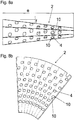
- the pyramid-shaped hollow body 2 is made by folding a prefabricated, essentially disk segment-shaped part (see Figure 8b ) created.
- Figure 7c shows the detail C.
- Figure 7b the upper part of the pyramid can be seen.
- folding the pyramid must be attached along one edge. This can be done by means of a plug connection or a hook. It is also conceivable to push a clamping strip over the parallel protruding folds. Furthermore, it is conceivable that To screw or rivet seams, whereby a clamping strip can also be used here to improve the appearance.
- the height e of the hollow body 2 can be between 0.5 m and 2 m, preferably between 0.75 m and 1.5 m and particularly preferably between 1 m and 1.2 m. In this special embodiment, the height e is 1.1 m.
- the width a of the hollow body 2 can be between 0.2 m and 1 m, preferably between 0.3 m and 0.6 m and particularly preferably between 0.4 m and 0.5 m. In this special embodiment the width a is 0.406 m.
- the angle f at which the sides of the pyramid-shaped hollow body 2 are inclined relative to the vertical can be between 2 ° and 20 °, preferably between 3.5 ° and 10 ° and particularly preferably between 6 ° and 7 °. In this special embodiment, the angle f is 6.3 °.
- FIGS. 9a to 9c show a side view, a top view and a view from below of the adapted sack 22.
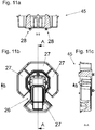
- FIG. 10a to 10c An extension of the embodiments from the Figures 1a to 1c , 2 , 3 such as 4a to 4c is in the Figures 10a to 10c as well as 11a to 11c and 12a to 12c.
- This extension relates to a substructure 45 on which the plant container 1 according to the invention can be arranged.
- the substructure 45 is constructed in several parts (in particular Figure 10c ).
- the substructure 45 has four flat bed containers 27. Of course, any other number of flat bed containers 27 can also be used, which appears advantageous to those skilled in the art.
- a drawer 26 (could also be designed as a closable cavity). This can be used for plant waste or for composting.
- the drawer 26 is designed integrally with one of the flat bed containers 27. Wheels 28 are arranged on a central support part 29 of the substructure 45, which in the Figures 11a, 11c as well as 12a and 12b can be seen. As a result, the entire arrangement can be shifted easily, which is particularly advantageous in confined spaces.
- Figures 12a to 12c two sectional views and a plan view of the entire arrangement with the drawer 26 open.
- FIGS. 14a to 14d relate to a further embodiment of the invention.
- the hollow body 2 is designed in the form of an erected cuboid, the openings 4 for the tubular elements 5 being arranged on one of the end faces.
- a flat bed container 27 can also be connected upstream or attached.
- a drawer 26 can also be implemented in this embodiment.
- the flat bed containers 27 can be used (in all embodiments) for filling with plant substrate 3 and for planting. This is particularly advantageous for plants that have relatively deep roots (example: carrots).
- the shape of the hollow body 2 per se is not essential. Only a non-horizontal surface on which openings 4 for the pipe elements 5 can be arranged is advantageous. The inclination of this surface can be selected according to aspects known to those skilled in the art, such as solar radiation and space requirements.
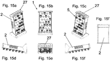
- the Figures 15 to 15f show a further embodiment, which of the Figures 13a to 13d and 14a to 14d is similar.
- the hollow body 2 is not set up in the form of a cuboid at a 90 ° angle, but rather is arranged at an incline. This has the advantage that the rays of the sun, which are inclined in most cases, are used more effectively because a larger cross-sectional area is presented from the point of view of the incident sun rays (analogy to the vineyard).
- the flat bed container 27 is arranged on top of the cavity 2 (that is, placed on top). This can save more space.
- the Figures 16a to 16b show various exploded views of the embodiment from FIGS Figures 15a to 15f .
- the hollow body 2 is formed by a base body 33, which by sliding a front plate 34 and putting on a lid 35 - containing the flat bed container 27 - becomes the cavity 2.
- the flat bed container 27 can be covered by an additional cover 36.
- the covered position is shown.
- Figures 17a and 17b represent additional aspects of a tubular element 5 according to the invention, which freely relate to the embodiments from FIGS Figures 5a to 5d and 6a to 6c can be combined.
- the widening 14 can have a holder for an additional plant substrate.
- An example would be a coconut tablet deposited on a cross 32 arranged in the widening 14.
- Such a cross 32 can also be designed such that it can be broken out if the additional holder is not needed.
- a substrate layer structure is easily made possible (i.e. for example growth substrate (garden soil) in the hollow body 2, plant-specific cultivation soil in the tubular element 5 and a coconut tablet with a seed in the widening 14).
- the pipe element 5 supports an additional root irrigation.
- a small tube 31 which is arranged, for example, just below the widening 14.
- a small opening can also be used.
- the root irrigation can be connected to a liquid reservoir or the like by means of a hose.
- the supply of liquid can also be controlled or regulated - for example using a soil moisture sensor.
- the root irrigation of several pipe elements 5 can be connected, so that a common root irrigation for several pipe elements 5 is created.
- the root irrigation of the individual pipe elements 5 can be connected in parallel and / or in series.
Landscapes
- Life Sciences & Earth Sciences (AREA)
- Environmental Sciences (AREA)
- Cultivation Receptacles Or Flower-Pots, Or Pots For Seedlings (AREA)
Claims (14)
- Jardinière (1) avec un corps creux (2) pour recevoir un substrat végétal (3), en particulier de la terre, laquelle présente des ouvertures (4) et des éléments tubulaires (5) disposés au niveau des ouvertures (4), lesquels présentent un cintrage (6) et/ou un pli, caractérisée en ce que- les éléments tubulaires (5) peuvent être fixés de manière amovible au niveau du corps creux (2) au moyen d'une fermeture à baïonnette (9, 10) et- les éléments tubulaires (5) sont fabriqués en plusieurs parties à partir de matière plastique par moulage par injection.
- Jardinière selon la revendication 1, caractérisée en ce que des extrémités (7), pointant de manière à s'éloigner du corps creux (2), des éléments tubulaires (5) pointent sensiblement vers le haut.
- Jardinière selon la revendication 1 ou 2, caractérisée en ce que les éléments tubulaires (5) présentent respectivement un moignon de tube (8) dépassant à l'intérieur du corps creux (2) - de préférence tronqué de manière oblique.
- Jardinière selon la revendication 3, caractérisée en ce qu'une lame (11) pour transpercer un sac (22) contenant le substrat végétal (3) est prévue au niveau du moignon de tube (8).
- Jardinière selon la revendication 3 ou 4, caractérisée en ce qu'une ouverture d'évacuation (12) pour évacuer un excédent de liquide est disposée au niveau d'un côté inférieur du moignon de tube (8).
- Jardinière selon l'une quelconque des revendications 1 à 5, caractérisée en ce que l'extrémité (7), pointant de manière à s'éloigner du corps creux (2), des éléments tubulaires (5) présente une extension (14).
- Jardinière selon l'une quelconque des revendications 1 à 6, caractérisée en ce que respectivement un non-tissé (15) pour le transport d'humidité vers l'extrémité (7), pointant de manière à s'éloigner du corps creux (2), des éléments tubulaires (5) est prévu dans les éléments tubulaires (5).
- Jardinière selon l'une quelconque des revendications 1 à 7, caractérisée en ce que des lamelles (16) sont disposées au niveau d'une paroi intérieure inférieure des éléments tubulaires (5).
- Jardinière selon l'une quelconque des revendications 1 à 8, caractérisée en ce que le corps creux (2) est produit à partir de matière plastique.
- Jardinière selon l'une quelconque des revendications 1 à 9, caractérisée en ce que les éléments tubulaires (5) présentent une charnière en film (17) et/ou une liaison de type queue-d'aronde.
- Jardinière selon l'une quelconque des revendications 1 à 10, caractérisée en ce que le corps creux (2) est disposé sur une base (45), qui comprend de préférence un tiroir (26) et/ou un espace creux pouvant être fermé pour des déchets et/ou du compost.
- Jardinière selon l'une quelconque des revendications 1 à 11 avec un tube descendant (18) dépassant dans le corps creux (2), caractérisée en ce- qu'est disposée au niveau d'une extrémité supérieure du tube descendant (18) une pièce de liaison (19), au moyen de laquelle un contenant (20) pour du liquide, en particulier de l'eau, peut être raccordé au tube descendant,- que le tube descendant (18) est fermé au niveau d'une extrémité inférieure, et- que le tube descendant (18) présente une pluralité d'ouvertures, dont le diamètre est respectivement inférieur à 1,5 mm, de manière préférée inférieur à 1 mm, et de manière particulièrement préférée inférieur à 0,75 mm, et/ou que le tube descendant est produit à partir d'un matériau poreux.
- Jardinière selon la revendication 12, dans laquelle le tube descendant est produit à partir d'un matériau poreux, caractérisée en ce que le matériau poreux présente un diamètre de pore compris entre 0,5 µm et 10 µm, de manière préférée entre 1 µm et 5 µm et de manière particulièrement préférée entre 1 µm et 3 µm.
- Utilisation d'un élément tubulaire, lequel présente un cintrage (6) et/ou un pli, pour recevoir un substrat végétal (3), dans une jardinière selon l'une quelconque des revendications 1 à 13, dans laquelle- les éléments tubulaires (5) peuvent être fixés de manière amovible au niveau du corps creux (2) au moyen d'une fermeture à baïonnette (9, 10), et- les éléments tubulaires (5) sont fabriqués en plusieurs parties à partir de matière plastique par moulage par injection.
Applications Claiming Priority (1)
| Application Number | Priority Date | Filing Date | Title |
|---|---|---|---|
| AT372015 | 2015-01-29 |
Publications (2)
| Publication Number | Publication Date |
|---|---|
| EP3050427A1 EP3050427A1 (fr) | 2016-08-03 |
| EP3050427B1 true EP3050427B1 (fr) | 2020-09-16 |
Family
ID=54849747
Family Applications (1)
| Application Number | Title | Priority Date | Filing Date |
|---|---|---|---|
| EP15003535.0A Active EP3050427B1 (fr) | 2015-01-29 | 2015-12-11 | Jardinière |
Country Status (2)
| Country | Link |
|---|---|
| EP (1) | EP3050427B1 (fr) |
| AT (1) | AT14882U1 (fr) |
Families Citing this family (2)
| Publication number | Priority date | Publication date | Assignee | Title |
|---|---|---|---|---|
| CN108934557A (zh) * | 2018-06-13 | 2018-12-07 | 佛山淼图科技有限公司 | 一种家用迷你葱蒜园 |
| DE102022128357A1 (de) * | 2022-10-26 | 2024-05-02 | Legat N. Holding GmbH | Pflanzmodul für einen hängenden Garten |
Family Cites Families (11)
| Publication number | Priority date | Publication date | Assignee | Title |
|---|---|---|---|---|
| DE3223644A1 (de) | 1982-06-24 | 1983-12-29 | Josef 8033 Mammendorf Reindl | Pflanzbehaelter |
| DE3225263C2 (de) * | 1982-07-06 | 1984-05-24 | Werner 4690 Herne Herold | Einrichtung zur Haltung von Pflanzen mit einer ein geschlossenes System bildenden Pflanzsäule |
| US5265376A (en) * | 1989-01-09 | 1993-11-30 | Less Karl H | Arrangement in plant columns |
| IL105601A (en) * | 1993-05-04 | 1997-06-10 | N C A Ltd | Plant holder |
| US5555676A (en) * | 1994-11-03 | 1996-09-17 | A.C.T., Inc. | Vertical planter apparatus and method |
| DE29716900U1 (de) * | 1997-09-20 | 1997-11-06 | Lahr, Helmut, 55270 Klein-Winternheim | Pflanzenbehälter mit weicher Außenhaut und seitlichen, stabilen Pflanzöffnungen |
| US6615542B2 (en) * | 2001-11-14 | 2003-09-09 | Larry Austen Ware | Plant growth unit |
| JP2005080623A (ja) * | 2003-09-11 | 2005-03-31 | Hiroshi Ueno | 植物養液栽培方法 |
| US7171782B2 (en) | 2004-02-02 | 2007-02-06 | Felknor Ventures, Llc | Planter for growing plants |
| GB2482654A (en) * | 2010-06-07 | 2012-02-15 | Antony Roch | A vertical planting system |
| FR2995503A1 (fr) * | 2012-09-18 | 2014-03-21 | Kevin Mazars | Support de culture verticale en colonne |
-
2015
- 2015-01-29 AT ATGM8076/2015U patent/AT14882U1/de not_active IP Right Cessation
- 2015-12-11 EP EP15003535.0A patent/EP3050427B1/fr active Active
Non-Patent Citations (1)
| Title |
|---|
| None * |
Also Published As
| Publication number | Publication date |
|---|---|
| AT14882U1 (de) | 2016-08-15 |
| EP3050427A1 (fr) | 2016-08-03 |
Similar Documents
| Publication | Publication Date | Title |
|---|---|---|
| EP3481736B1 (fr) | Récipient empilable comprenant des moyens d'évacuation de liquide du côté du fond | |
| DE2744143A1 (de) | Verfahren zum zuechten von pflanzen und behaelter zur durchfuehrung des verfahrens | |
| DE102008049361A1 (de) | Einsatz-Behälter | |
| WO1996025844A1 (fr) | Substrat pour plantes | |
| AT520103A1 (de) | Blumentopf | |
| DE102015005912A1 (de) | Schneckensicheres Pflanzengestell | |
| DE69901241T2 (de) | Kulturkastenanlage | |
| DE2742795A1 (de) | Kastenkonstruktion zum ziehen von pflanzen | |
| EP3050427B1 (fr) | Jardinière | |
| DE1931374U (de) | Zu einer einheit zusammengefasste pflanztopfgruppe fuer saemlinge. | |
| DE4215401C1 (fr) | ||
| EP2071937A2 (fr) | Pot pour plante | |
| DE3816866A1 (de) | Begruenungselement | |
| DE3307428A1 (de) | Behaelter zum einpflanzen von gewaechsen | |
| DE202022106982U1 (de) | Pflanzmodul für einen hängenden Garten | |
| DE60004824T2 (de) | Pflanzenstütze und verfahren zum herstellen einer solchen pflanzenstütze | |
| DE102022128357A1 (de) | Pflanzmodul für einen hängenden Garten | |
| DE202022106034U1 (de) | Pflanzmodul für einen hängenden Garten | |
| DE102009034157A1 (de) | Vorrichtung zur Aufnahme, zum Speichern und zur selbstregulierenden Abgabe von Flüssigkeit an ein Bedarfsgefäß | |
| EP1479289B1 (fr) | Dispositif d'irrigation d'un tombe | |
| DE2015209C3 (de) | Vorrichtung zum Kultivieren von Epiphyten | |
| EP3909419B1 (fr) | Seaux d'arrosage | |
| DE4201118A1 (de) | Pflanzgefaess, insbesondere in form eines blumenkastens | |
| EP4385317A1 (fr) | Module de plantation pour jardin suspendu | |
| DE68906143T2 (de) | Vorrichtung und verfahren zur kuenstlichen bewaesserung von pflanzen. |
Legal Events
| Date | Code | Title | Description |
|---|---|---|---|
| PUAI | Public reference made under article 153(3) epc to a published international application that has entered the european phase |
Free format text: ORIGINAL CODE: 0009012 |
|
| AK | Designated contracting states |
Kind code of ref document: A1 Designated state(s): AL AT BE BG CH CY CZ DE DK EE ES FI FR GB GR HR HU IE IS IT LI LT LU LV MC MK MT NL NO PL PT RO RS SE SI SK SM TR |
|
| AX | Request for extension of the european patent |
Extension state: BA ME |
|
| STAA | Information on the status of an ep patent application or granted ep patent |
Free format text: STATUS: REQUEST FOR EXAMINATION WAS MADE |
|
| 17P | Request for examination filed |
Effective date: 20170202 |
|
| RBV | Designated contracting states (corrected) |
Designated state(s): AL AT BE BG CH CY CZ DE DK EE ES FI FR GB GR HR HU IE IS IT LI LT LU LV MC MK MT NL NO PL PT RO RS SE SI SK SM TR |
|
| STAA | Information on the status of an ep patent application or granted ep patent |
Free format text: STATUS: EXAMINATION IS IN PROGRESS |
|
| 17Q | First examination report despatched |
Effective date: 20190412 |
|
| GRAP | Despatch of communication of intention to grant a patent |
Free format text: ORIGINAL CODE: EPIDOSNIGR1 |
|
| STAA | Information on the status of an ep patent application or granted ep patent |
Free format text: STATUS: GRANT OF PATENT IS INTENDED |
|
| INTG | Intention to grant announced |
Effective date: 20200414 |
|
| RIC1 | Information provided on ipc code assigned before grant |
Ipc: A01G 9/02 20180101AFI20200327BHEP |
|
| GRAS | Grant fee paid |
Free format text: ORIGINAL CODE: EPIDOSNIGR3 |
|
| GRAA | (expected) grant |
Free format text: ORIGINAL CODE: 0009210 |
|
| STAA | Information on the status of an ep patent application or granted ep patent |
Free format text: STATUS: THE PATENT HAS BEEN GRANTED |
|
| AK | Designated contracting states |
Kind code of ref document: B1 Designated state(s): AL AT BE BG CH CY CZ DE DK EE ES FI FR GB GR HR HU IE IS IT LI LT LU LV MC MK MT NL NO PL PT RO RS SE SI SK SM TR |
|
| REG | Reference to a national code |
Ref country code: GB Ref legal event code: FG4D Free format text: NOT ENGLISH |
|
| REG | Reference to a national code |
Ref country code: CH Ref legal event code: EP |
|
| REG | Reference to a national code |
Ref country code: DE Ref legal event code: R096 Ref document number: 502015013452 Country of ref document: DE |
|
| REG | Reference to a national code |
Ref country code: IE Ref legal event code: FG4D Free format text: LANGUAGE OF EP DOCUMENT: GERMAN |
|
| REG | Reference to a national code |
Ref country code: AT Ref legal event code: REF Ref document number: 1313257 Country of ref document: AT Kind code of ref document: T Effective date: 20201015 |
|
| REG | Reference to a national code |
Ref country code: CH Ref legal event code: NV Representative=s name: ISLER AND PEDRAZZINI AG, CH |
|
| PG25 | Lapsed in a contracting state [announced via postgrant information from national office to epo] |
Ref country code: HR Free format text: LAPSE BECAUSE OF FAILURE TO SUBMIT A TRANSLATION OF THE DESCRIPTION OR TO PAY THE FEE WITHIN THE PRESCRIBED TIME-LIMIT Effective date: 20200916 Ref country code: BG Free format text: LAPSE BECAUSE OF FAILURE TO SUBMIT A TRANSLATION OF THE DESCRIPTION OR TO PAY THE FEE WITHIN THE PRESCRIBED TIME-LIMIT Effective date: 20201216 Ref country code: SE Free format text: LAPSE BECAUSE OF FAILURE TO SUBMIT A TRANSLATION OF THE DESCRIPTION OR TO PAY THE FEE WITHIN THE PRESCRIBED TIME-LIMIT Effective date: 20200916 Ref country code: NO Free format text: LAPSE BECAUSE OF FAILURE TO SUBMIT A TRANSLATION OF THE DESCRIPTION OR TO PAY THE FEE WITHIN THE PRESCRIBED TIME-LIMIT Effective date: 20201216 Ref country code: GR Free format text: LAPSE BECAUSE OF FAILURE TO SUBMIT A TRANSLATION OF THE DESCRIPTION OR TO PAY THE FEE WITHIN THE PRESCRIBED TIME-LIMIT Effective date: 20201217 Ref country code: FI Free format text: LAPSE BECAUSE OF FAILURE TO SUBMIT A TRANSLATION OF THE DESCRIPTION OR TO PAY THE FEE WITHIN THE PRESCRIBED TIME-LIMIT Effective date: 20200916 |
|
| REG | Reference to a national code |
Ref country code: NL Ref legal event code: MP Effective date: 20200916 |
|
| PG25 | Lapsed in a contracting state [announced via postgrant information from national office to epo] |
Ref country code: RS Free format text: LAPSE BECAUSE OF FAILURE TO SUBMIT A TRANSLATION OF THE DESCRIPTION OR TO PAY THE FEE WITHIN THE PRESCRIBED TIME-LIMIT Effective date: 20200916 Ref country code: LV Free format text: LAPSE BECAUSE OF FAILURE TO SUBMIT A TRANSLATION OF THE DESCRIPTION OR TO PAY THE FEE WITHIN THE PRESCRIBED TIME-LIMIT Effective date: 20200916 |
|
| REG | Reference to a national code |
Ref country code: LT Ref legal event code: MG4D |
|
| PG25 | Lapsed in a contracting state [announced via postgrant information from national office to epo] |
Ref country code: EE Free format text: LAPSE BECAUSE OF FAILURE TO SUBMIT A TRANSLATION OF THE DESCRIPTION OR TO PAY THE FEE WITHIN THE PRESCRIBED TIME-LIMIT Effective date: 20200916 Ref country code: RO Free format text: LAPSE BECAUSE OF FAILURE TO SUBMIT A TRANSLATION OF THE DESCRIPTION OR TO PAY THE FEE WITHIN THE PRESCRIBED TIME-LIMIT Effective date: 20200916 Ref country code: SM Free format text: LAPSE BECAUSE OF FAILURE TO SUBMIT A TRANSLATION OF THE DESCRIPTION OR TO PAY THE FEE WITHIN THE PRESCRIBED TIME-LIMIT Effective date: 20200916 Ref country code: PT Free format text: LAPSE BECAUSE OF FAILURE TO SUBMIT A TRANSLATION OF THE DESCRIPTION OR TO PAY THE FEE WITHIN THE PRESCRIBED TIME-LIMIT Effective date: 20210118 Ref country code: NL Free format text: LAPSE BECAUSE OF FAILURE TO SUBMIT A TRANSLATION OF THE DESCRIPTION OR TO PAY THE FEE WITHIN THE PRESCRIBED TIME-LIMIT Effective date: 20200916 Ref country code: LT Free format text: LAPSE BECAUSE OF FAILURE TO SUBMIT A TRANSLATION OF THE DESCRIPTION OR TO PAY THE FEE WITHIN THE PRESCRIBED TIME-LIMIT Effective date: 20200916 Ref country code: CZ Free format text: LAPSE BECAUSE OF FAILURE TO SUBMIT A TRANSLATION OF THE DESCRIPTION OR TO PAY THE FEE WITHIN THE PRESCRIBED TIME-LIMIT Effective date: 20200916 |
|
| PG25 | Lapsed in a contracting state [announced via postgrant information from national office to epo] |
Ref country code: IS Free format text: LAPSE BECAUSE OF FAILURE TO SUBMIT A TRANSLATION OF THE DESCRIPTION OR TO PAY THE FEE WITHIN THE PRESCRIBED TIME-LIMIT Effective date: 20210116 Ref country code: PL Free format text: LAPSE BECAUSE OF FAILURE TO SUBMIT A TRANSLATION OF THE DESCRIPTION OR TO PAY THE FEE WITHIN THE PRESCRIBED TIME-LIMIT Effective date: 20200916 Ref country code: AL Free format text: LAPSE BECAUSE OF FAILURE TO SUBMIT A TRANSLATION OF THE DESCRIPTION OR TO PAY THE FEE WITHIN THE PRESCRIBED TIME-LIMIT Effective date: 20200916 Ref country code: ES Free format text: LAPSE BECAUSE OF FAILURE TO SUBMIT A TRANSLATION OF THE DESCRIPTION OR TO PAY THE FEE WITHIN THE PRESCRIBED TIME-LIMIT Effective date: 20200916 |
|
| REG | Reference to a national code |
Ref country code: DE Ref legal event code: R097 Ref document number: 502015013452 Country of ref document: DE |
|
| PG25 | Lapsed in a contracting state [announced via postgrant information from national office to epo] |
Ref country code: SK Free format text: LAPSE BECAUSE OF FAILURE TO SUBMIT A TRANSLATION OF THE DESCRIPTION OR TO PAY THE FEE WITHIN THE PRESCRIBED TIME-LIMIT Effective date: 20200916 |
|
| PLBE | No opposition filed within time limit |
Free format text: ORIGINAL CODE: 0009261 |
|
| STAA | Information on the status of an ep patent application or granted ep patent |
Free format text: STATUS: NO OPPOSITION FILED WITHIN TIME LIMIT |
|
| 26N | No opposition filed |
Effective date: 20210617 |
|
| PG25 | Lapsed in a contracting state [announced via postgrant information from national office to epo] |
Ref country code: SI Free format text: LAPSE BECAUSE OF FAILURE TO SUBMIT A TRANSLATION OF THE DESCRIPTION OR TO PAY THE FEE WITHIN THE PRESCRIBED TIME-LIMIT Effective date: 20200916 Ref country code: MC Free format text: LAPSE BECAUSE OF FAILURE TO SUBMIT A TRANSLATION OF THE DESCRIPTION OR TO PAY THE FEE WITHIN THE PRESCRIBED TIME-LIMIT Effective date: 20200916 Ref country code: DK Free format text: LAPSE BECAUSE OF FAILURE TO SUBMIT A TRANSLATION OF THE DESCRIPTION OR TO PAY THE FEE WITHIN THE PRESCRIBED TIME-LIMIT Effective date: 20200916 |
|
| REG | Reference to a national code |
Ref country code: BE Ref legal event code: MM Effective date: 20201231 |
|
| PG25 | Lapsed in a contracting state [announced via postgrant information from national office to epo] |
Ref country code: IE Free format text: LAPSE BECAUSE OF NON-PAYMENT OF DUE FEES Effective date: 20201211 Ref country code: LU Free format text: LAPSE BECAUSE OF NON-PAYMENT OF DUE FEES Effective date: 20201211 |
|
| PGFP | Annual fee paid to national office [announced via postgrant information from national office to epo] |
Ref country code: GB Payment date: 20211229 Year of fee payment: 7 Ref country code: AT Payment date: 20211221 Year of fee payment: 7 Ref country code: FR Payment date: 20211231 Year of fee payment: 7 |
|
| PGFP | Annual fee paid to national office [announced via postgrant information from national office to epo] |
Ref country code: IT Payment date: 20211221 Year of fee payment: 7 Ref country code: CH Payment date: 20211220 Year of fee payment: 7 |
|
| PGFP | Annual fee paid to national office [announced via postgrant information from national office to epo] |
Ref country code: DE Payment date: 20220105 Year of fee payment: 7 |
|
| PG25 | Lapsed in a contracting state [announced via postgrant information from national office to epo] |
Ref country code: TR Free format text: LAPSE BECAUSE OF FAILURE TO SUBMIT A TRANSLATION OF THE DESCRIPTION OR TO PAY THE FEE WITHIN THE PRESCRIBED TIME-LIMIT Effective date: 20200916 Ref country code: MT Free format text: LAPSE BECAUSE OF FAILURE TO SUBMIT A TRANSLATION OF THE DESCRIPTION OR TO PAY THE FEE WITHIN THE PRESCRIBED TIME-LIMIT Effective date: 20200916 Ref country code: CY Free format text: LAPSE BECAUSE OF FAILURE TO SUBMIT A TRANSLATION OF THE DESCRIPTION OR TO PAY THE FEE WITHIN THE PRESCRIBED TIME-LIMIT Effective date: 20200916 |
|
| PG25 | Lapsed in a contracting state [announced via postgrant information from national office to epo] |
Ref country code: MK Free format text: LAPSE BECAUSE OF FAILURE TO SUBMIT A TRANSLATION OF THE DESCRIPTION OR TO PAY THE FEE WITHIN THE PRESCRIBED TIME-LIMIT Effective date: 20200916 |
|
| PG25 | Lapsed in a contracting state [announced via postgrant information from national office to epo] |
Ref country code: BE Free format text: LAPSE BECAUSE OF NON-PAYMENT OF DUE FEES Effective date: 20201231 |
|
| REG | Reference to a national code |
Ref country code: DE Ref legal event code: R119 Ref document number: 502015013452 Country of ref document: DE |
|
| REG | Reference to a national code |
Ref country code: CH Ref legal event code: PL |
|
| REG | Reference to a national code |
Ref country code: AT Ref legal event code: MM01 Ref document number: 1313257 Country of ref document: AT Kind code of ref document: T Effective date: 20221211 |
|
| GBPC | Gb: european patent ceased through non-payment of renewal fee |
Effective date: 20221211 |
|
| PG25 | Lapsed in a contracting state [announced via postgrant information from national office to epo] |
Ref country code: LI Free format text: LAPSE BECAUSE OF NON-PAYMENT OF DUE FEES Effective date: 20221231 Ref country code: GB Free format text: LAPSE BECAUSE OF NON-PAYMENT OF DUE FEES Effective date: 20221211 Ref country code: DE Free format text: LAPSE BECAUSE OF NON-PAYMENT OF DUE FEES Effective date: 20230701 Ref country code: CH Free format text: LAPSE BECAUSE OF NON-PAYMENT OF DUE FEES Effective date: 20221231 Ref country code: AT Free format text: LAPSE BECAUSE OF NON-PAYMENT OF DUE FEES Effective date: 20221211 |
|
| PG25 | Lapsed in a contracting state [announced via postgrant information from national office to epo] |
Ref country code: FR Free format text: LAPSE BECAUSE OF NON-PAYMENT OF DUE FEES Effective date: 20221231 |
|
| PG25 | Lapsed in a contracting state [announced via postgrant information from national office to epo] |
Ref country code: IT Free format text: LAPSE BECAUSE OF NON-PAYMENT OF DUE FEES Effective date: 20221211 |