EP3050733A1 - Radantriebsvorrichtung - Google Patents
Radantriebsvorrichtung Download PDFInfo
- Publication number
- EP3050733A1 EP3050733A1 EP14849238.2A EP14849238A EP3050733A1 EP 3050733 A1 EP3050733 A1 EP 3050733A1 EP 14849238 A EP14849238 A EP 14849238A EP 3050733 A1 EP3050733 A1 EP 3050733A1
- Authority
- EP
- European Patent Office
- Prior art keywords
- wheel
- motor
- electric motor
- lubricating oil
- drive device
- Prior art date
- Legal status (The legal status is an assumption and is not a legal conclusion. Google has not performed a legal analysis and makes no representation as to the accuracy of the status listed.)
- Withdrawn
Links
- 239000010687 lubricating oil Substances 0.000 claims abstract description 60
- 239000003921 oil Substances 0.000 claims abstract description 52
- 230000007246 mechanism Effects 0.000 claims abstract description 14
- 238000001816 cooling Methods 0.000 claims abstract description 7
- 239000003638 chemical reducing agent Substances 0.000 claims description 44
- 239000000463 material Substances 0.000 claims description 8
- 239000011347 resin Substances 0.000 claims description 8
- 229920005989 resin Polymers 0.000 claims description 8
- 238000001514 detection method Methods 0.000 abstract description 5
- 230000033001 locomotion Effects 0.000 description 9
- 230000005484 gravity Effects 0.000 description 8
- 230000005856 abnormality Effects 0.000 description 7
- 230000002093 peripheral effect Effects 0.000 description 7
- 238000004891 communication Methods 0.000 description 4
- 238000009413 insulation Methods 0.000 description 3
- 238000005096 rolling process Methods 0.000 description 3
- 238000007664 blowing Methods 0.000 description 2
- 238000010586 diagram Methods 0.000 description 2
- 230000000694 effects Effects 0.000 description 2
- 238000005461 lubrication Methods 0.000 description 2
- 239000000696 magnetic material Substances 0.000 description 2
- 238000012986 modification Methods 0.000 description 2
- 230000004048 modification Effects 0.000 description 2
- 239000004065 semiconductor Substances 0.000 description 2
- 239000002966 varnish Substances 0.000 description 2
- 230000001133 acceleration Effects 0.000 description 1
- 238000006243 chemical reaction Methods 0.000 description 1
- 238000002485 combustion reaction Methods 0.000 description 1
- 238000010276 construction Methods 0.000 description 1
- 230000008878 coupling Effects 0.000 description 1
- 238000010168 coupling process Methods 0.000 description 1
- 238000005859 coupling reaction Methods 0.000 description 1
- 238000002474 experimental method Methods 0.000 description 1
- 239000011810 insulating material Substances 0.000 description 1
- 230000001050 lubricating effect Effects 0.000 description 1
- 238000000034 method Methods 0.000 description 1
- 229910001172 neodymium magnet Inorganic materials 0.000 description 1
- 230000009467 reduction Effects 0.000 description 1
- 230000004044 response Effects 0.000 description 1
- 238000004088 simulation Methods 0.000 description 1
- 239000000725 suspension Substances 0.000 description 1
- 230000001360 synchronised effect Effects 0.000 description 1
Images



Classifications
-
- H—ELECTRICITY
- H02—GENERATION; CONVERSION OR DISTRIBUTION OF ELECTRIC POWER
- H02K—DYNAMO-ELECTRIC MACHINES
- H02K1/00—Details of the magnetic circuit
- H02K1/06—Details of the magnetic circuit characterised by the shape, form or construction
- H02K1/22—Rotating parts of the magnetic circuit
- H02K1/32—Rotating parts of the magnetic circuit with channels or ducts for flow of cooling medium
-
- B—PERFORMING OPERATIONS; TRANSPORTING
- B60—VEHICLES IN GENERAL
- B60K—ARRANGEMENT OR MOUNTING OF PROPULSION UNITS OR OF TRANSMISSIONS IN VEHICLES; ARRANGEMENT OR MOUNTING OF PLURAL DIVERSE PRIME-MOVERS IN VEHICLES; AUXILIARY DRIVES FOR VEHICLES; INSTRUMENTATION OR DASHBOARDS FOR VEHICLES; ARRANGEMENTS IN CONNECTION WITH COOLING, AIR INTAKE, GAS EXHAUST OR FUEL SUPPLY OF PROPULSION UNITS IN VEHICLES
- B60K1/00—Arrangement or mounting of electrical propulsion units
-
- B—PERFORMING OPERATIONS; TRANSPORTING
- B60—VEHICLES IN GENERAL
- B60K—ARRANGEMENT OR MOUNTING OF PROPULSION UNITS OR OF TRANSMISSIONS IN VEHICLES; ARRANGEMENT OR MOUNTING OF PLURAL DIVERSE PRIME-MOVERS IN VEHICLES; AUXILIARY DRIVES FOR VEHICLES; INSTRUMENTATION OR DASHBOARDS FOR VEHICLES; ARRANGEMENTS IN CONNECTION WITH COOLING, AIR INTAKE, GAS EXHAUST OR FUEL SUPPLY OF PROPULSION UNITS IN VEHICLES
- B60K17/00—Arrangement or mounting of transmissions in vehicles
- B60K17/04—Arrangement or mounting of transmissions in vehicles characterised by arrangement, location or kind of gearing
- B60K17/043—Transmission unit disposed in on near the vehicle wheel, or between the differential gear unit and the wheel
- B60K17/046—Transmission unit disposed in on near the vehicle wheel, or between the differential gear unit and the wheel with planetary gearing having orbital motion
-
- B—PERFORMING OPERATIONS; TRANSPORTING
- B60—VEHICLES IN GENERAL
- B60K—ARRANGEMENT OR MOUNTING OF PROPULSION UNITS OR OF TRANSMISSIONS IN VEHICLES; ARRANGEMENT OR MOUNTING OF PLURAL DIVERSE PRIME-MOVERS IN VEHICLES; AUXILIARY DRIVES FOR VEHICLES; INSTRUMENTATION OR DASHBOARDS FOR VEHICLES; ARRANGEMENTS IN CONNECTION WITH COOLING, AIR INTAKE, GAS EXHAUST OR FUEL SUPPLY OF PROPULSION UNITS IN VEHICLES
- B60K7/00—Disposition of motor in, or adjacent to, traction wheel
- B60K7/0007—Disposition of motor in, or adjacent to, traction wheel the motor being electric
-
- B—PERFORMING OPERATIONS; TRANSPORTING
- B60—VEHICLES IN GENERAL
- B60L—PROPULSION OF ELECTRICALLY-PROPELLED VEHICLES; SUPPLYING ELECTRIC POWER FOR AUXILIARY EQUIPMENT OF ELECTRICALLY-PROPELLED VEHICLES; ELECTRODYNAMIC BRAKE SYSTEMS FOR VEHICLES IN GENERAL; MAGNETIC SUSPENSION OR LEVITATION FOR VEHICLES; MONITORING OPERATING VARIABLES OF ELECTRICALLY-PROPELLED VEHICLES; ELECTRIC SAFETY DEVICES FOR ELECTRICALLY-PROPELLED VEHICLES
- B60L15/00—Methods, circuits, or devices for controlling the traction-motor speed of electrically-propelled vehicles
- B60L15/20—Methods, circuits, or devices for controlling the traction-motor speed of electrically-propelled vehicles for control of the vehicle or its driving motor to achieve a desired performance, e.g. speed, torque, programmed variation of speed
-
- B—PERFORMING OPERATIONS; TRANSPORTING
- B60—VEHICLES IN GENERAL
- B60L—PROPULSION OF ELECTRICALLY-PROPELLED VEHICLES; SUPPLYING ELECTRIC POWER FOR AUXILIARY EQUIPMENT OF ELECTRICALLY-PROPELLED VEHICLES; ELECTRODYNAMIC BRAKE SYSTEMS FOR VEHICLES IN GENERAL; MAGNETIC SUSPENSION OR LEVITATION FOR VEHICLES; MONITORING OPERATING VARIABLES OF ELECTRICALLY-PROPELLED VEHICLES; ELECTRIC SAFETY DEVICES FOR ELECTRICALLY-PROPELLED VEHICLES
- B60L3/00—Electric devices on electrically-propelled vehicles for safety purposes; Monitoring operating variables, e.g. speed, deceleration or energy consumption
- B60L3/0023—Detecting, eliminating, remedying or compensating for drive train abnormalities, e.g. failures within the drive train
- B60L3/0061—Detecting, eliminating, remedying or compensating for drive train abnormalities, e.g. failures within the drive train relating to electrical machines
-
- B—PERFORMING OPERATIONS; TRANSPORTING
- B60—VEHICLES IN GENERAL
- B60L—PROPULSION OF ELECTRICALLY-PROPELLED VEHICLES; SUPPLYING ELECTRIC POWER FOR AUXILIARY EQUIPMENT OF ELECTRICALLY-PROPELLED VEHICLES; ELECTRODYNAMIC BRAKE SYSTEMS FOR VEHICLES IN GENERAL; MAGNETIC SUSPENSION OR LEVITATION FOR VEHICLES; MONITORING OPERATING VARIABLES OF ELECTRICALLY-PROPELLED VEHICLES; ELECTRIC SAFETY DEVICES FOR ELECTRICALLY-PROPELLED VEHICLES
- B60L50/00—Electric propulsion with power supplied within the vehicle
- B60L50/50—Electric propulsion with power supplied within the vehicle using propulsion power supplied by batteries or fuel cells
- B60L50/51—Electric propulsion with power supplied within the vehicle using propulsion power supplied by batteries or fuel cells characterised by AC-motors
-
- H—ELECTRICITY
- H02—GENERATION; CONVERSION OR DISTRIBUTION OF ELECTRIC POWER
- H02K—DYNAMO-ELECTRIC MACHINES
- H02K11/00—Structural association of dynamo-electric machines with electric components or with devices for shielding, monitoring or protection
- H02K11/20—Structural association of dynamo-electric machines with electric components or with devices for shielding, monitoring or protection for measuring, monitoring, testing, protecting or switching
- H02K11/25—Devices for sensing temperature, or actuated thereby
-
- H—ELECTRICITY
- H02—GENERATION; CONVERSION OR DISTRIBUTION OF ELECTRIC POWER
- H02K—DYNAMO-ELECTRIC MACHINES
- H02K7/00—Arrangements for handling mechanical energy structurally associated with dynamo-electric machines, e.g. structural association with mechanical driving motors or auxiliary dynamo-electric machines
- H02K7/08—Structural association with bearings
-
- H—ELECTRICITY
- H02—GENERATION; CONVERSION OR DISTRIBUTION OF ELECTRIC POWER
- H02K—DYNAMO-ELECTRIC MACHINES
- H02K7/00—Arrangements for handling mechanical energy structurally associated with dynamo-electric machines, e.g. structural association with mechanical driving motors or auxiliary dynamo-electric machines
- H02K7/10—Structural association with clutches, brakes, gears, pulleys or mechanical starters
- H02K7/116—Structural association with clutches, brakes, gears, pulleys or mechanical starters with gears
-
- H—ELECTRICITY
- H02—GENERATION; CONVERSION OR DISTRIBUTION OF ELECTRIC POWER
- H02K—DYNAMO-ELECTRIC MACHINES
- H02K9/00—Arrangements for cooling or ventilating
- H02K9/19—Arrangements for cooling or ventilating for machines with closed casing and closed-circuit cooling using a liquid cooling medium, e.g. oil
-
- B—PERFORMING OPERATIONS; TRANSPORTING
- B60—VEHICLES IN GENERAL
- B60K—ARRANGEMENT OR MOUNTING OF PROPULSION UNITS OR OF TRANSMISSIONS IN VEHICLES; ARRANGEMENT OR MOUNTING OF PLURAL DIVERSE PRIME-MOVERS IN VEHICLES; AUXILIARY DRIVES FOR VEHICLES; INSTRUMENTATION OR DASHBOARDS FOR VEHICLES; ARRANGEMENTS IN CONNECTION WITH COOLING, AIR INTAKE, GAS EXHAUST OR FUEL SUPPLY OF PROPULSION UNITS IN VEHICLES
- B60K1/00—Arrangement or mounting of electrical propulsion units
- B60K2001/003—Arrangement or mounting of electrical propulsion units with means for cooling the electrical propulsion units
- B60K2001/006—Arrangement or mounting of electrical propulsion units with means for cooling the electrical propulsion units the electric motors
-
- B—PERFORMING OPERATIONS; TRANSPORTING
- B60—VEHICLES IN GENERAL
- B60K—ARRANGEMENT OR MOUNTING OF PROPULSION UNITS OR OF TRANSMISSIONS IN VEHICLES; ARRANGEMENT OR MOUNTING OF PLURAL DIVERSE PRIME-MOVERS IN VEHICLES; AUXILIARY DRIVES FOR VEHICLES; INSTRUMENTATION OR DASHBOARDS FOR VEHICLES; ARRANGEMENTS IN CONNECTION WITH COOLING, AIR INTAKE, GAS EXHAUST OR FUEL SUPPLY OF PROPULSION UNITS IN VEHICLES
- B60K7/00—Disposition of motor in, or adjacent to, traction wheel
- B60K2007/0038—Disposition of motor in, or adjacent to, traction wheel the motor moving together with the wheel axle
-
- B—PERFORMING OPERATIONS; TRANSPORTING
- B60—VEHICLES IN GENERAL
- B60K—ARRANGEMENT OR MOUNTING OF PROPULSION UNITS OR OF TRANSMISSIONS IN VEHICLES; ARRANGEMENT OR MOUNTING OF PLURAL DIVERSE PRIME-MOVERS IN VEHICLES; AUXILIARY DRIVES FOR VEHICLES; INSTRUMENTATION OR DASHBOARDS FOR VEHICLES; ARRANGEMENTS IN CONNECTION WITH COOLING, AIR INTAKE, GAS EXHAUST OR FUEL SUPPLY OF PROPULSION UNITS IN VEHICLES
- B60K7/00—Disposition of motor in, or adjacent to, traction wheel
- B60K2007/0092—Disposition of motor in, or adjacent to, traction wheel the motor axle being coaxial to the wheel axle
-
- B—PERFORMING OPERATIONS; TRANSPORTING
- B60—VEHICLES IN GENERAL
- B60L—PROPULSION OF ELECTRICALLY-PROPELLED VEHICLES; SUPPLYING ELECTRIC POWER FOR AUXILIARY EQUIPMENT OF ELECTRICALLY-PROPELLED VEHICLES; ELECTRODYNAMIC BRAKE SYSTEMS FOR VEHICLES IN GENERAL; MAGNETIC SUSPENSION OR LEVITATION FOR VEHICLES; MONITORING OPERATING VARIABLES OF ELECTRICALLY-PROPELLED VEHICLES; ELECTRIC SAFETY DEVICES FOR ELECTRICALLY-PROPELLED VEHICLES
- B60L2220/00—Electrical machine types; Structures or applications thereof
- B60L2220/10—Electrical machine types
- B60L2220/14—Synchronous machines
-
- B—PERFORMING OPERATIONS; TRANSPORTING
- B60—VEHICLES IN GENERAL
- B60L—PROPULSION OF ELECTRICALLY-PROPELLED VEHICLES; SUPPLYING ELECTRIC POWER FOR AUXILIARY EQUIPMENT OF ELECTRICALLY-PROPELLED VEHICLES; ELECTRODYNAMIC BRAKE SYSTEMS FOR VEHICLES IN GENERAL; MAGNETIC SUSPENSION OR LEVITATION FOR VEHICLES; MONITORING OPERATING VARIABLES OF ELECTRICALLY-PROPELLED VEHICLES; ELECTRIC SAFETY DEVICES FOR ELECTRICALLY-PROPELLED VEHICLES
- B60L2220/00—Electrical machine types; Structures or applications thereof
- B60L2220/40—Electrical machine applications
- B60L2220/44—Wheel Hub motors, i.e. integrated in the wheel hub
-
- B—PERFORMING OPERATIONS; TRANSPORTING
- B60—VEHICLES IN GENERAL
- B60L—PROPULSION OF ELECTRICALLY-PROPELLED VEHICLES; SUPPLYING ELECTRIC POWER FOR AUXILIARY EQUIPMENT OF ELECTRICALLY-PROPELLED VEHICLES; ELECTRODYNAMIC BRAKE SYSTEMS FOR VEHICLES IN GENERAL; MAGNETIC SUSPENSION OR LEVITATION FOR VEHICLES; MONITORING OPERATING VARIABLES OF ELECTRICALLY-PROPELLED VEHICLES; ELECTRIC SAFETY DEVICES FOR ELECTRICALLY-PROPELLED VEHICLES
- B60L2220/00—Electrical machine types; Structures or applications thereof
- B60L2220/50—Structural details of electrical machines
-
- B—PERFORMING OPERATIONS; TRANSPORTING
- B60—VEHICLES IN GENERAL
- B60L—PROPULSION OF ELECTRICALLY-PROPELLED VEHICLES; SUPPLYING ELECTRIC POWER FOR AUXILIARY EQUIPMENT OF ELECTRICALLY-PROPELLED VEHICLES; ELECTRODYNAMIC BRAKE SYSTEMS FOR VEHICLES IN GENERAL; MAGNETIC SUSPENSION OR LEVITATION FOR VEHICLES; MONITORING OPERATING VARIABLES OF ELECTRICALLY-PROPELLED VEHICLES; ELECTRIC SAFETY DEVICES FOR ELECTRICALLY-PROPELLED VEHICLES
- B60L2240/00—Control parameters of input or output; Target parameters
- B60L2240/10—Vehicle control parameters
- B60L2240/36—Temperature of vehicle components or parts
-
- B—PERFORMING OPERATIONS; TRANSPORTING
- B60—VEHICLES IN GENERAL
- B60L—PROPULSION OF ELECTRICALLY-PROPELLED VEHICLES; SUPPLYING ELECTRIC POWER FOR AUXILIARY EQUIPMENT OF ELECTRICALLY-PROPELLED VEHICLES; ELECTRODYNAMIC BRAKE SYSTEMS FOR VEHICLES IN GENERAL; MAGNETIC SUSPENSION OR LEVITATION FOR VEHICLES; MONITORING OPERATING VARIABLES OF ELECTRICALLY-PROPELLED VEHICLES; ELECTRIC SAFETY DEVICES FOR ELECTRICALLY-PROPELLED VEHICLES
- B60L2240/00—Control parameters of input or output; Target parameters
- B60L2240/40—Drive Train control parameters
- B60L2240/42—Drive Train control parameters related to electric machines
- B60L2240/425—Temperature
-
- B—PERFORMING OPERATIONS; TRANSPORTING
- B60—VEHICLES IN GENERAL
- B60Y—INDEXING SCHEME RELATING TO ASPECTS CROSS-CUTTING VEHICLE TECHNOLOGY
- B60Y2306/00—Other features of vehicle sub-units
- B60Y2306/03—Lubrication
-
- Y—GENERAL TAGGING OF NEW TECHNOLOGICAL DEVELOPMENTS; GENERAL TAGGING OF CROSS-SECTIONAL TECHNOLOGIES SPANNING OVER SEVERAL SECTIONS OF THE IPC; TECHNICAL SUBJECTS COVERED BY FORMER USPC CROSS-REFERENCE ART COLLECTIONS [XRACs] AND DIGESTS
- Y02—TECHNOLOGIES OR APPLICATIONS FOR MITIGATION OR ADAPTATION AGAINST CLIMATE CHANGE
- Y02T—CLIMATE CHANGE MITIGATION TECHNOLOGIES RELATED TO TRANSPORTATION
- Y02T10/00—Road transport of goods or passengers
- Y02T10/60—Other road transportation technologies with climate change mitigation effect
- Y02T10/64—Electric machine technologies in electromobility
-
- Y—GENERAL TAGGING OF NEW TECHNOLOGICAL DEVELOPMENTS; GENERAL TAGGING OF CROSS-SECTIONAL TECHNOLOGIES SPANNING OVER SEVERAL SECTIONS OF THE IPC; TECHNICAL SUBJECTS COVERED BY FORMER USPC CROSS-REFERENCE ART COLLECTIONS [XRACs] AND DIGESTS
- Y02—TECHNOLOGIES OR APPLICATIONS FOR MITIGATION OR ADAPTATION AGAINST CLIMATE CHANGE
- Y02T—CLIMATE CHANGE MITIGATION TECHNOLOGIES RELATED TO TRANSPORTATION
- Y02T10/00—Road transport of goods or passengers
- Y02T10/60—Other road transportation technologies with climate change mitigation effect
- Y02T10/70—Energy storage systems for electromobility, e.g. batteries
-
- Y—GENERAL TAGGING OF NEW TECHNOLOGICAL DEVELOPMENTS; GENERAL TAGGING OF CROSS-SECTIONAL TECHNOLOGIES SPANNING OVER SEVERAL SECTIONS OF THE IPC; TECHNICAL SUBJECTS COVERED BY FORMER USPC CROSS-REFERENCE ART COLLECTIONS [XRACs] AND DIGESTS
- Y02—TECHNOLOGIES OR APPLICATIONS FOR MITIGATION OR ADAPTATION AGAINST CLIMATE CHANGE
- Y02T—CLIMATE CHANGE MITIGATION TECHNOLOGIES RELATED TO TRANSPORTATION
- Y02T10/00—Road transport of goods or passengers
- Y02T10/60—Other road transportation technologies with climate change mitigation effect
- Y02T10/72—Electric energy management in electromobility
Definitions
- the present invention relates to a wheel drive device to be used in a drive wheel such as in an electric vehicle.
- an in-wheel motor drive device With respect to an in-wheel motor drive device, a technique has been proposed in which, in order to reduce overload on a motor which drives a wheel, a temperature of a coil of the motor is detected by a temperature detector, to limit a drive current for the motor (Patent Document 1).
- the in-wheel motor drive device cools the motor by guiding, radially outward from inside a main shaft, a part of lubricating oil which is also used for cooling, and by injecting the lubricating oil to the motor coil, for example.
- Patent Document 1 JP Laid-open Patent Publication No. 2012-178917
- An object of the present invention is to provide a wheel drive device that can suppress decrease of coil temperature detection accuracy, and that can improve responsibility in controlling an electric motor.
- a wheel drive device of a first invention in the present invention is a wheel drive device including: an electric motor configured to drive a wheel; a wheel bearing configured to transmit a rotation of the electric motor to the wheel and configured to rotationally support the wheel; an oil supply mechanism configured to guide a lubricating oil, radially outward from inside a main shaft of the electric motor, the lubricating oil being also used for cooling, and configured to inject the lubricating oil to coils of a motor stator of the electric motor (configuration defined in preamble), and a temperature detector configured to detect a temperature of the coils and disposed above a center of the main shaft and in a gap between the coils adjacent to each other in a circumferential direction.
- the oil supply mechanism guides, radially outward from inside the main shaft of the electric motor, a part of the lubricating oil which is also used for cooling, and injects the lubricating oil to the coils of the electric motor. Accordingly, the electric motor is cooled.
- the lubricating oil having been injected to the coils moves, due to the gravity, to a lower portion along the stator and the like of the electric motor, for example.
- the temperature detector detects the temperature of the coils.
- the temperature detector is disposed above the center of the main shaft and in the gap between the coils adjacent to each other in the circumferential direction, it is possible to prevent the temperature detector from directly receiving the injected lubricating oil, and in addition, it is possible to prevent the temperature detector from coming into contact with the lubricating oil moving along the stator and the like due to the gravity. Accordingly, decrease of the coil temperature detection accuracy can be suppressed, and responsibility in controlling the electric motor can be improved. Moreover, since the temperature detector is disposed in the gap between the coils, the temperature detector can be more easily disposed, than in a structure, for example, where the temperature detector is embedded in a coil bobbin or the like.
- a wheel drive device of a second invention in the present invention is the device having the configuration defined in preamble of the first invention, and a temperature detector configured to detect the temperature of the coils and disposed above the center of the main shaft and on an end face, of one of the coils, that is on a radially outward side of the electric motor.
- each coil may be wound about a direction orthogonal to the motor axis.
- the temperature detector Since the temperature detector is disposed in this manner, it is possible to prevent the temperature detector from directly receiving the injected lubricating oil, and in addition, it is possible to prevent the temperature detector from coming into contact with the lubricating oil moving along the stator and the like due to the gravity. With this configuration, decrease of the coil temperature detection accuracy can be suppressed, and responsibility in controlling the electric motor can be improved.
- the temperature detector and the coils may be impregnated with a resin material.
- a resin material an insulating varnish can be used, for example. In this case, it is possible to ensure the insulating property of the coils, and in addition, it is possible to more reliably prevent the temperature detector from coming into contact with the lubricating oil.
- the wheel drive device may include a reducer configured to reduce a speed of rotation of the electric motor and to transmit resultant rotation to the wheel bearing.
- the oil supply mechanism may include an oil path configured to supply the lubricating oil to the reducer. Any one of the wheel drive devices described above may be an in-wheel motor drive device.
- this in-wheel motor drive device includes; an electric motor 1 which drives a wheel (not shown); a reducer or reduction gear 2 which reduces the speed of rotation of the electric motor 1; a wheel bearing 5 which is rotated by an output member 4 being coaxial with an input shaft 3 (referred to as reducer input shaft 3) of the reducer 2; temperature detector Sa; and an oil supply mechanism Jk.
- the reducer 2 is interposed between the wheel bearing 5 and the electric motor 1, and the hub of a wheel being a drive wheel supported by the wheel bearing 5 is coaxially coupled with a motor rotation shaft 6 of the electric motor 1.
- a suspension (not shown) of the vehicle is coupled with a reducer housing 7 which houses the reducer 2.
- the term “outboard” represents one side of the vehicle body away from the longitudinal center of the vehicle body and the term “inboard” represents the other side of the vehicle body close to the longitudinal center of the vehicle body, when the in-wheel motor drive device is supported in the vehicle.
- the electric motor 1 is a radial-gap-type IPM motor (so-called interior permanent magnet synchronous motor) in which a radial gap is provided between a motor stator 9 fixed to a motor housing 8 and a motor rotor 10 installed to a motor rotation shaft 6.
- IPM motor interior permanent magnet synchronous motor
- bearings 11 and 12 are provided so as to be spaced from each other along the axial direction, and the motor rotation shaft 6 being the main shaft is rotatably supported by the bearings 11 and 12.
- the motor rotation shaft 6 transmits a drive force of the electric motor 1 to the reducer 2.
- a flange portion 6a extending radially outward is provided about an axially intermediate portion of the motor rotation shaft 6, and the motor rotor 10 is mounted to the flange portion 6a via a rotor fixing member 13.
- One end in the axial direction of the reducer input shaft 3 extends in the motor rotation shaft 6 and is in spline-fit with the motor rotation shaft 6.
- a bearing 14a is fitted in a cup portion 4a of the output member 4, and a bearing 14b is fitted in a cylindrical coupling member 26 coupled to the cup portion 4a via inner pins 22.
- the reducer input shaft 3 is rotatably supported by the bearings 14a, 14b, 11, and 12.
- the reducer input shaft 3 and the motor rotation shaft 6 are, while integrally fitted, rotatably supported by the bearings 11, 12, 14a, and 14b.
- Eccentric segments 15 and 16 are provided on the outer peripheral surface of the reducer input shaft 3 in the reducer housing 7.
- the eccentric segments 15 and 16 are provided, 180° out of phase with each other, such that the respective centrifugal forces caused by eccentric motions of the eccentric segments 15 and 16 can be canceled with each other.
- the reducer 2 is a cycloid reducer which includes: an outer pin housing Ih; curvilinear plates 17 and 18; a plurality of outer pins 19; a motion converter mechanism 20; and a counterweight 21.
- Fig. 2 is a cross-sectional view showing the reducer portion taken along a line II-II shown in Fig. 1 .
- the curvilinear plates 17 and 18 each having an outer shape formed in a gentle wavy trochoid curve are mounted to the eccentric segments 15 and 16 via a bearing 85.
- a plurality of outer pins 19 which guide, on the outer periphery side thereof, eccentric motions of the curvilinear plates 17 and 18 are provided inside the reducer housing 7.
- a plurality of inner pins 22 mounted to the cup portion 4a ( Fig. 1 ) are respectively inserted in and engaged with a plurality of circular through-holes 89 which are formed in the curvilinear plates 17 and 18.
- each outer pin 19 has a bearing 92 fitted thereto and each inner pin 22 has a bearing 93 fitted thereto.
- each outer pin 19 is supported by an outer ring 92a of the bearing 92 at both ends, and thus, is in rolling contact with the outer peripheral surfaces of the curvilinear plates 17 and 18 via the bearing 92.
- an outer ring 93a of the bearing 93 fitted to each inner pin 22 is in rolling contact with the inner periphery of each through-hole 89 of the curvilinear plates 17 and 18.
- each outer pin 19 and the outer peripheries of the curvilinear plates 17 and 18, and the contact friction between each inner pin 22 and the inner periphery of each through-hole 89 can be reduced.
- the eccentric motions of the curvilinear plates 17 and 18 can be smoothly transmitted as a rotary motion to an inner member 5a of the wheel bearing 5, as shown in Fig. 1 . That is, when the motor rotation shaft 6 rotates, the curvilinear plates 17 and 18 provided at the reducer input shaft 3 which rotates integrally with the motor rotation shaft 6 perform the respective eccentric motions. At this time, each outer pin 19 engages, in rolling contact, with the outer peripheral surfaces of the curvilinear plates 17 and 18 performing eccentric motions.
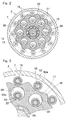
- Fig. 4 is a cross-sectional view of the motor portion taken along a line IV-IV shown in Fig. 1 .
- the motor rotor 10 of the electric motor 1 includes, for example: a core portion (not shown) made of a soft magnetic material; and a permanent magnet (not shown) provided in the core portion.
- a permanent magnet a neodymium magnet is used, for example.
- the motor stator 9 includes, for example: a stator core portion 77 made of a soft magnetic material; coils 78; and insulating members 79.
- the stator core portion 77 has a ring shape whose outer peripheral surface is circular in cross section. Inside the inner peripheral surface of the stator core portion 77, a plurality of teeth 77a protruding radially inwards are formed so as to be arranged along the circumferential direction.
- each coil 78 is wound around its corresponding tooth 77a of the stator core portion 77.
- the coil 78 is wound about a direction orthogonal to a motor axis L1.
- each coil 78 wound around its corresponding tooth 77a includes coil ends 78a which protrude toward the inboard side and the outboard side relative to the widthwise ends of the stator core portion 77, respectively.
- lubricating oil is injected from the oil supply mechanism Jk described later.
- Fig. 5 is a partial enlarged view of a part A shown in Fig. 4 .
- the temperature detector Sa which detects the temperature of the coils 78 is disposed.
- the temperature detector Sa is disposed above the center L1 of the motor rotation shaft 6 ( Fig. 1 ).
- the coils 78, 78 adjacent to each other are surrounded, together with the temperature detector Sa, by an insulating member 79 made of an insulating material.
- a thermistor or a thermocouple is used, for example.
- a thermistor whose cost is lower and which is more robust than a thermocouple, is preferably used.
- the oil supply mechanism Jk is an axial oil supply mechanism which supplies lubricating oil to be used both in lubrication for the reducer 2 and in cooling of the electric motor 1.
- the oil supply mechanism Jk includes a lubricating oil flow path 30, a motor shaft oil path 32, a reducer oil path 31, and an oil pump 28.
- the lubricating oil flow path 30 is provided in the motor housing 8, and the motor shaft oil path 32 is provided along the axis of the motor rotation shaft 6 of the electric motor 1 and is in communication with the lubricating oil flow path 30.
- the reducer oil path 31 is provided in the reducer 2 and is in communication with the motor shaft oil path 32 and a lubricating oil storage portion 29, thereby supplying the lubricating oil to the reducer 2.
- the reducer oil path 31 includes an input shaft oil path 36, an oil supply hole 37, and an oil discharge hole 38.
- the input shaft oil path 36 is in communication with the motor shaft oil path 32, and extends in the axial direction inside the reducer input shaft 3 from the inboard-side end toward the outboard side.
- the oil supply hole 37 extends radially outward from a position, in the axial direction, in the input shaft oil path 36, where the eccentric segments 15 and 16 are provided.
- the reducer housing 7 is provided with the oil discharge hole 38 which discharges, to the lubricating oil storage portion 29, the lubricating oil having been used in lubrication of the reducer 2.
- the oil pump 28 sucks the lubricating oil stored in the lubricating oil storage portion 29, from a suction hole in the lubricating oil storage portion 29, and circulates the lubricating oil via the lubricating oil flow path 30 to the motor shaft oil path 32 and the reducer oil path 31.
- the oil pump 28 is a cycloid pump which includes, for example: an inner rotor which rotates in association with the rotation of the output member 4; an outer rotor which rotates in a following manner in association with the rotation of the inner rotor; a pump chamber; a suction port; and a discharge port, which are not shown.
- the outer rotor rotates in a following manner. Since the inner rotor and the outer rotor rotate respectively about different rotation axes at that time, a volume of the pump chamber is continuously varied.
- the lubricating oil stored in the lubricating oil storage portion 29 is sucked through the suction port, and then is pressure-fed through the discharge port into the lubricating oil flow path 30.
- the lubricating oil is guided from the lubricating oil flow path 30 to the motor shaft oil path 32.
- a part of the lubricating oil is guided from the motor shaft oil path 32 into an annular gap ⁇ 1 via through-hole 6b extending radially outward from the motor rotation shaft 6.
- a part of the lubricating oil passes from the annular gap ⁇ 1 through an oil path 13a which extends radially outward and which is formed in the rotor fixing member 13, whereby the motor rotor 10 is cooled.
- the lubricating oil is injected to the inner peripheral surfaces of the coil ends 78a under the centrifugal force of the motor rotor 10 and the pressure from the oil pump 28, whereby the coils 78 are cooled. Accordingly, the entirety of the electric motor 1 is cooled.
- the lubricating oil having been used in this cooling moves downwardly due to the gravity, drops into a lower portion of the motor housing 8, and then, is stored in the lubricating oil storage portion 29 which is in communication with the lower portion of the motor housing 8.
- the lubricating oil guided from the motor shaft oil path 32 to the oil supply hole 37 lubricates the inside of the reducer 2. Centrifugal force acts on the lubricating oil discharged from the outer-diameter-side opening end of the oil supply hole 37, and thus, the lubricating oil moves radially outward in the reducer housing 7 while lubricating portions to be lubricated in the reducer 2. Then, the lubricating oil moves downwardly due to the gravity, to be stored in the lubricating oil storage portion 29 through the oil discharge hole 38.
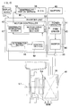
- FIG. 6 is a block diagram showing a control system of the in-wheel motor drive device.
- a control device U1 includes: an ECU 39 which is an electrical control unit performing comprehensive or entire control of the vehicle; and an inverter unit 40 which controls the electric motor 1 for traveling in accordance with commands from the ECU 39.
- the inverter unit 40 includes: a power circuitry 41 provided in each electric motor 1; and a motor controller 42 which controls the power circuitry 41.
- the motor controller 42 has a function of outputting, to the ECU 39, various types of information held in the motor controller 42, such as detected values or control values regarding the in-wheel motor (IWM) which includes the electric motor 1, the reducer 2 and the wheel bearing 5.
- IWM in-wheel motor
- the power circuitry 41 includes: an inverter 44 which converts a DC power from a battery 43 into a three-phase AC power to be used to drive the electric motor 1; and a PWM driver 45 which controls the inverter 44.
- the inverter 44 includes a plurality of semiconductor switching elements (not shown), and the PWM driver 45 performs pulse width modulation on an inputted current command and sends ON/OFF commands to the semiconductor switching elements.
- the motor controller 42 includes a computer, programs which are executed by the computer, and electronic circuits.
- the motor controller 42 includes a motor drive control section 33 as a basic control section.
- the motor drive control section 33 performs conversion of an acceleration/deceleration command such as a torque command sent from the ECU 39 being primary control unit into a current command, and sends the current command to the PWM driver 45.
- the motor drive control section 33 obtains, from a current detector 35, a motor current value that is to be provided from the inverter 44 to the electric motor 1, thereby performing current feedback control.
- the motor drive control section 33 obtains the rotation angle of the motor rotor 10 in the electric motor 1 from an angle sensor 46, thereby to perform vector control.
- the motor controller 42 is provided with abnormality notification section 47, a determination section 48, and a control section 49.
- the determination section 48 determines whether or not the temperature of the coils 78 detected by the temperature detector Sa has exceeded a predetermined threshold value.
- the threshold value is obtained as appropriate through an experiment or simulation, for example, based on the relationship between the temperature of the coils 78 and the time, which causes insulation at coils 78. Whether or not insulation has occurred at the coils 78 can be determined by comparing a motor current value corresponding to a motor voltage applied to the electric motor 1, with a reference value in the case of no insulation.
- the control section 49 instructs the power circuitry 41, through the motor drive control section 33, to reduce the current value for the electric motor 1, by a predetermined proportion to the present current or by a predetermined value, for example.
- the abnormality notification section 47 outputs an information indicating the abnormality to the ECU 39.
- abnormality display section 50 provided in the ECU 39 causes, for example, a display device 51 provided in a dashboard or the like of the vehicle, to show a presentation that indicates the abnormality.
- the oil supply mechanism Jk causes a part of the lubricating oil to pass through the motor shaft oil path 32, and then sequentially, through the through-hole 6b, the annular gap ⁇ 1, and the oil path 13a, whereby the motor rotor 10 is cooled. Further, from the oil blowing holes 13aa of the oil path 13a, the lubricating oil is injected to the inner peripheral surfaces of the coil ends 78a under the centrifugal force of the motor rotor 10 and the pressure from the oil pump 28, whereby the coils 78 are cooled. Accordingly, the entirety of the electric motor 1 is cooled. The lubricating oil having been injected to the coils 78 moves to the lower portion along the motor stator 9 and the like due to the gravity.
- the control section 49 instructs the power circuitry 41, through the motor drive control section 33, to reduce the current value for the electric motor 1, by a predetermined proportion to the present current or by a predetermined value, for example. Since the temperature detector Sa is disposed above the center L1 of the motor rotation shaft 6 and in the gap ⁇ between the coils 78, 78 adjacent to each other in the circumferential direction, it is possible to prevent the temperature detector Sa from directly receiving the injected lubricating oil, and in addition, it is possible to prevent the temperature detector Sa from coming into contact with the lubricating oil moving along the motor stator 9 and the like due to the gravity.
- the temperature detector Sa is disposed in the gap ⁇ between the coils 78, 78, the temperature detector Sa can be more easily disposed, than in a structure, for example, where the temperature detector Sa is embedded in a coil bobbin or the like.
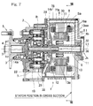
- Fig. 7 is a cross-sectional view of an in-wheel motor drive device according to another embodiment of the present invention.
- Fig. 8 is a cross-sectional view of the motor portion taken along a line VIII-VIII shown in Fig. 7 .
- each coil 78 may be wound about a direction orthogonal to the motor axis L1, and the temperature detector Sa may be disposed above the center L1 of the motor rotation shaft 6 and on an end face 78b ( Fig. 8 ), of one coil end 78a, which is on the radially outward side of the electric motor.
- the temperature detector Sa Since the temperature detector Sa is disposed in this manner, it is possible to prevent the temperature detector Sa from directly receiving the injected lubricating oil, and in addition, it is possible to prevent the temperature detector Sa from coming into contact with the lubricating oil moving along the motor stator 9 and the like due to the gravity.
- Fig. 9 shows still another embodiment in which a resin material 52 is provided instead of the insulating member 79 of the motor stator 9 in the first embodiment shown in Figs. 1 to 6 .
- the temperature detector Sa and the coils 78 may be impregnated with the resin material 52.
- the resin material 52 an insulating varnish can be used, for example. In this case, it is possible to ensure the insulating property of the coils 78, and in addition, it is possible to more reliably prevent the temperature detector Sa from coming into contact with the lubricating oil.
- the temperature detector Sa and the coils 78 may be impregnated with a resin material.
- the coil 78 wound around a bobbin which is not shown in Figs. 1 to 9 may be used.
- the oil pump 28 may be provided outside the housings 7, 8 in the in-wheel motor drive device, and the oil pump 28 may be driven by a drive source different from that used for the in-wheel motor drive device.
- the wheel drive device A has been described using the in-wheel motor drive device as an example, but not being limited thereto, the wheel drive device A may be of an on-board type. With respect to the wheel drive device A, an example has been shown in which a cycloid-type reducer is used, but not being limited thereto, a planetary reducer, a parallel shaft reducer, or another type of reducer may be used. Further, the wheel drive device A may be of a so-called direct motor type which does not use a reducer.
- the term "electric vehicle” represents a concept that encompasses all types of vehicles that obtain drive force from an electric power, and thus, should be construed as including, for example, hybrid cars or the like that use the in-wheel motor drive device A and an internal combustion engine in combination.
Landscapes
- Engineering & Computer Science (AREA)
- Power Engineering (AREA)
- Transportation (AREA)
- Mechanical Engineering (AREA)
- Combustion & Propulsion (AREA)
- Chemical & Material Sciences (AREA)
- Sustainable Energy (AREA)
- Sustainable Development (AREA)
- Life Sciences & Earth Sciences (AREA)
- Microelectronics & Electronic Packaging (AREA)
- Arrangement Or Mounting Of Propulsion Units For Vehicles (AREA)
- Electric Propulsion And Braking For Vehicles (AREA)
- Motor Or Generator Cooling System (AREA)
Applications Claiming Priority (2)
| Application Number | Priority Date | Filing Date | Title |
|---|---|---|---|
| JP2013199341A JP2015063266A (ja) | 2013-09-26 | 2013-09-26 | 車輪用駆動装置 |
| PCT/JP2014/074206 WO2015045903A1 (ja) | 2013-09-26 | 2014-09-12 | 車輪用駆動装置 |
Publications (2)
| Publication Number | Publication Date |
|---|---|
| EP3050733A1 true EP3050733A1 (de) | 2016-08-03 |
| EP3050733A4 EP3050733A4 (de) | 2017-07-12 |
Family
ID=52743045
Family Applications (1)
| Application Number | Title | Priority Date | Filing Date |
|---|---|---|---|
| EP14849238.2A Withdrawn EP3050733A4 (de) | 2013-09-26 | 2014-09-12 | Radantriebsvorrichtung |
Country Status (5)
| Country | Link |
|---|---|
| US (1) | US20160204679A1 (de) |
| EP (1) | EP3050733A4 (de) |
| JP (1) | JP2015063266A (de) |
| CN (1) | CN105579270A (de) |
| WO (1) | WO2015045903A1 (de) |
Families Citing this family (12)
| Publication number | Priority date | Publication date | Assignee | Title |
|---|---|---|---|---|
| EP3310645B1 (de) * | 2015-06-19 | 2021-10-20 | Robert Bosch GmbH | Elektrofahrzeug und antriebssystem für ein elektrofahrzeug |
| JP2017017889A (ja) | 2015-07-02 | 2017-01-19 | Ntn株式会社 | モータ駆動装置 |
| JP2017163645A (ja) * | 2016-03-08 | 2017-09-14 | Ntn株式会社 | 車両用駆動装置 |
| JP2017192224A (ja) * | 2016-04-14 | 2017-10-19 | Ntn株式会社 | 車両用駆動装置 |
| JP6500878B2 (ja) * | 2016-11-16 | 2019-04-17 | トヨタ自動車株式会社 | 回転電機の冷却構造 |
| WO2018103047A1 (zh) * | 2016-12-08 | 2018-06-14 | 深圳市大疆灵眸科技有限公司 | 电机、云台、拍摄装置、飞行器及电机、云台的控制方法 |
| JP6272525B1 (ja) * | 2017-04-21 | 2018-01-31 | 三菱電機株式会社 | 回転電機 |
| JP6671447B1 (ja) * | 2018-11-28 | 2020-03-25 | 三菱電機株式会社 | 回転電機およびその製造方法 |
| KR102588326B1 (ko) * | 2018-12-27 | 2023-10-11 | 현대트랜시스 주식회사 | 인휠모터 파워트레인의 윤활시스템 |
| JP2021114824A (ja) * | 2020-01-17 | 2021-08-05 | コアレスモータ株式会社 | コアレス回転電気機械 |
| JP7351412B2 (ja) * | 2020-04-10 | 2023-09-27 | 株式会社アイシン | 車両用駆動装置 |
| WO2022178868A1 (zh) * | 2021-02-26 | 2022-09-01 | 华为数字能源技术有限公司 | 动力总成及电动车 |
Family Cites Families (25)
| Publication number | Priority date | Publication date | Assignee | Title |
|---|---|---|---|---|
| US4712441A (en) * | 1985-05-13 | 1987-12-15 | Brunswick Valve & Control, Inc. | Position controlled linear actuator |
| US4862024A (en) * | 1987-12-14 | 1989-08-29 | United Technologies Corp. | Heat dissipation in an electric motor |
| US4922165A (en) * | 1988-06-06 | 1990-05-01 | General Electric Company | Core and slot liner |
| US4994700A (en) * | 1990-02-15 | 1991-02-19 | Sundstrand Corporation | Dynamoelectric machine oil-cooled stator winding |
| JP2894967B2 (ja) * | 1995-04-20 | 1999-05-24 | ファナック株式会社 | 電動機の鉄心の絶縁部材 |
| JP2921752B2 (ja) * | 1996-09-18 | 1999-07-19 | ファナック株式会社 | 電動機の巻線温度検出素子の取付け方法および取付け具 |
| JP4276579B2 (ja) * | 2004-05-17 | 2009-06-10 | トヨタ自動車株式会社 | インホイールモータに設けられる部品の搭載構造 |
| JP4952502B2 (ja) * | 2007-10-16 | 2012-06-13 | トヨタ自動車株式会社 | 温度検出素子固定構造、及びその製造方法、並びに金型 |
| EP2066008B1 (de) * | 2007-11-29 | 2011-08-03 | Siemens Aktiengesellschaft | Stator einer dynamoelektrischen Maschine mit Mitteln zur Temperaturerfassung |
| JP4325717B2 (ja) * | 2007-12-06 | 2009-09-02 | トヨタ自動車株式会社 | 車両駆動装置 |
| JP4877296B2 (ja) * | 2008-08-21 | 2012-02-15 | トヨタ自動車株式会社 | 駆動装置およびその制御装置 |
| JP2010252508A (ja) * | 2009-04-15 | 2010-11-04 | Nissan Motor Co Ltd | 温度検出素子の取付構造 |
| JP2010259271A (ja) * | 2009-04-27 | 2010-11-11 | Sanyo Electric Co Ltd | 電動モータ及び電動車輌 |
| JP5374333B2 (ja) * | 2009-11-27 | 2013-12-25 | Ntn株式会社 | インホイールモータ駆動装置 |
| DE102010030968B4 (de) * | 2010-07-06 | 2012-02-02 | Zf Friedrichshafen Ag | Temperatursensor und Anordnung zur Erfassung einer Temperatur einer elektrischen Maschine mit einem Temperatursensor |
| JP5614881B2 (ja) * | 2010-08-19 | 2014-10-29 | 三菱日立パワーシステムズ株式会社 | 電気機器 |
| DE102010063581A1 (de) * | 2010-10-21 | 2012-04-26 | Robert Bosch Gmbh | Stator einer elektrischen Maschine |
| JP5672984B2 (ja) * | 2010-11-04 | 2015-02-18 | アイシン精機株式会社 | 回転電機のステータ |
| JP5720185B2 (ja) * | 2010-11-04 | 2015-05-20 | アイシン精機株式会社 | 電動モータおよびその電動モータを用いた車両用駆動装置 |
| JP5731233B2 (ja) * | 2011-02-25 | 2015-06-10 | Ntn株式会社 | 電気自動車 |
| JP5957184B2 (ja) * | 2011-04-01 | 2016-07-27 | 本田技研工業株式会社 | 車両用駆動装置 |
| JP5811665B2 (ja) * | 2011-07-28 | 2015-11-11 | トヨタ自動車株式会社 | 回転電気 |
| JP5985178B2 (ja) * | 2011-11-24 | 2016-09-06 | Ntn株式会社 | モータの制御装置 |
| JP5848105B2 (ja) * | 2011-11-25 | 2016-01-27 | Ntn株式会社 | 電動車両の導電路 |
| US20130156071A1 (en) * | 2011-12-16 | 2013-06-20 | Remy Technologies, Llc | Electric Machine Including Insulated Slot Liner With Temperature Sensor |
-
2013
- 2013-09-26 JP JP2013199341A patent/JP2015063266A/ja active Pending
-
2014
- 2014-09-12 CN CN201480052296.XA patent/CN105579270A/zh active Pending
- 2014-09-12 EP EP14849238.2A patent/EP3050733A4/de not_active Withdrawn
- 2014-09-12 WO PCT/JP2014/074206 patent/WO2015045903A1/ja not_active Ceased
-
2016
- 2016-03-21 US US15/076,079 patent/US20160204679A1/en not_active Abandoned
Also Published As
| Publication number | Publication date |
|---|---|
| EP3050733A4 (de) | 2017-07-12 |
| WO2015045903A1 (ja) | 2015-04-02 |
| JP2015063266A (ja) | 2015-04-09 |
| US20160204679A1 (en) | 2016-07-14 |
| CN105579270A (zh) | 2016-05-11 |
Similar Documents
| Publication | Publication Date | Title |
|---|---|---|
| EP3050733A1 (de) | Radantriebsvorrichtung | |
| US10230323B2 (en) | Motor drive device | |
| US9701204B2 (en) | In-wheel motor drive device | |
| CN103947103B (zh) | 电动机的控制装置 | |
| US10207576B2 (en) | In-wheel motor drive device | |
| JP5893361B2 (ja) | モータの制御装置 | |
| CN103415413B (zh) | 电动机的诊断装置和诊断方法 | |
| US20130009522A1 (en) | Drive motor for electric vehicle | |
| CN103947100B (zh) | 电动汽车的电动机控制装置 | |
| JP5379541B2 (ja) | 電動駆動システム | |
| WO2019138965A1 (ja) | 車輪用軸受装置およびこの車輪用軸受装置を備えた車両 | |
| JP2014121941A (ja) | インホイールモータ駆動装置 | |
| US9184583B2 (en) | Electric automobile | |
| JP2018046742A (ja) | インホイールモータ駆動装置 | |
| JP6199454B2 (ja) | モータの制御装置 | |
| CN112140902A (zh) | 驱动控制装置 | |
| JP2018159625A (ja) | 異常診断装置 | |
| JP2015119525A (ja) | 電動車両の異常検知装置 | |
| JP2013104532A (ja) | インホイールモータ車両駆動装置 | |
| JP2008172975A (ja) | インホイールモータ駆動装置 |
Legal Events
| Date | Code | Title | Description |
|---|---|---|---|
| PUAI | Public reference made under article 153(3) epc to a published international application that has entered the european phase |
Free format text: ORIGINAL CODE: 0009012 |
|
| 17P | Request for examination filed |
Effective date: 20160322 |
|
| AK | Designated contracting states |
Kind code of ref document: A1 Designated state(s): AL AT BE BG CH CY CZ DE DK EE ES FI FR GB GR HR HU IE IS IT LI LT LU LV MC MK MT NL NO PL PT RO RS SE SI SK SM TR |
|
| AX | Request for extension of the european patent |
Extension state: BA ME |
|
| DAX | Request for extension of the european patent (deleted) | ||
| A4 | Supplementary search report drawn up and despatched |
Effective date: 20170613 |
|
| RIC1 | Information provided on ipc code assigned before grant |
Ipc: H02K 1/32 20060101ALI20170607BHEP Ipc: B60L 3/00 20060101ALI20170607BHEP Ipc: B60K 7/00 20060101AFI20170607BHEP Ipc: H02K 11/25 20160101ALI20170607BHEP |
|
| 17Q | First examination report despatched |
Effective date: 20190513 |
|
| STAA | Information on the status of an ep patent application or granted ep patent |
Free format text: STATUS: THE APPLICATION IS DEEMED TO BE WITHDRAWN |
|
| 18D | Application deemed to be withdrawn |
Effective date: 20190924 |