EP3050801B1 - Système de commande environnementale d'aéronef qui optimise la proportion de l'air extérieur à partir des moteurs, apu, sources d'air au sol et de l'air de la cabine remis en circulation pour maintenir le confort des occupants et maximiser l'économie de carburant - Google Patents
Système de commande environnementale d'aéronef qui optimise la proportion de l'air extérieur à partir des moteurs, apu, sources d'air au sol et de l'air de la cabine remis en circulation pour maintenir le confort des occupants et maximiser l'économie de carburant Download PDFInfo
- Publication number
- EP3050801B1 EP3050801B1 EP16152656.1A EP16152656A EP3050801B1 EP 3050801 B1 EP3050801 B1 EP 3050801B1 EP 16152656 A EP16152656 A EP 16152656A EP 3050801 B1 EP3050801 B1 EP 3050801B1
- Authority
- EP
- European Patent Office
- Prior art keywords
- air
- sensor
- environment
- ecs
- contaminant
- Prior art date
- Legal status (The legal status is an assumption and is not a legal conclusion. Google has not performed a legal analysis and makes no representation as to the accuracy of the status listed.)
- Active
Links
Images
Classifications
-
- B—PERFORMING OPERATIONS; TRANSPORTING
- B64—AIRCRAFT; AVIATION; COSMONAUTICS
- B64D—EQUIPMENT FOR FITTING IN OR TO AIRCRAFT; FLIGHT SUITS; PARACHUTES; ARRANGEMENT OR MOUNTING OF POWER PLANTS OR PROPULSION TRANSMISSIONS IN AIRCRAFT
- B64D13/00—Arrangements or adaptations of air-treatment apparatus for aircraft crew or passengers, or freight space
- B64D13/06—Arrangements or adaptations of air-treatment apparatus for aircraft crew or passengers, or freight space the air being conditioned
-
- B—PERFORMING OPERATIONS; TRANSPORTING
- B64—AIRCRAFT; AVIATION; COSMONAUTICS
- B64D—EQUIPMENT FOR FITTING IN OR TO AIRCRAFT; FLIGHT SUITS; PARACHUTES; ARRANGEMENT OR MOUNTING OF POWER PLANTS OR PROPULSION TRANSMISSIONS IN AIRCRAFT
- B64D13/00—Arrangements or adaptations of air-treatment apparatus for aircraft crew or passengers, or freight space
- B64D13/06—Arrangements or adaptations of air-treatment apparatus for aircraft crew or passengers, or freight space the air being conditioned
- B64D2013/0603—Environmental Control Systems
-
- B—PERFORMING OPERATIONS; TRANSPORTING
- B64—AIRCRAFT; AVIATION; COSMONAUTICS
- B64D—EQUIPMENT FOR FITTING IN OR TO AIRCRAFT; FLIGHT SUITS; PARACHUTES; ARRANGEMENT OR MOUNTING OF POWER PLANTS OR PROPULSION TRANSMISSIONS IN AIRCRAFT
- B64D13/00—Arrangements or adaptations of air-treatment apparatus for aircraft crew or passengers, or freight space
- B64D13/06—Arrangements or adaptations of air-treatment apparatus for aircraft crew or passengers, or freight space the air being conditioned
- B64D2013/0603—Environmental Control Systems
- B64D2013/0637—Environmental Control Systems with CO2 removers
-
- B—PERFORMING OPERATIONS; TRANSPORTING
- B64—AIRCRAFT; AVIATION; COSMONAUTICS
- B64D—EQUIPMENT FOR FITTING IN OR TO AIRCRAFT; FLIGHT SUITS; PARACHUTES; ARRANGEMENT OR MOUNTING OF POWER PLANTS OR PROPULSION TRANSMISSIONS IN AIRCRAFT
- B64D13/00—Arrangements or adaptations of air-treatment apparatus for aircraft crew or passengers, or freight space
- B64D13/06—Arrangements or adaptations of air-treatment apparatus for aircraft crew or passengers, or freight space the air being conditioned
- B64D2013/0603—Environmental Control Systems
- B64D2013/0688—Environmental Control Systems with means for recirculating cabin air
-
- B—PERFORMING OPERATIONS; TRANSPORTING
- B64—AIRCRAFT; AVIATION; COSMONAUTICS
- B64D—EQUIPMENT FOR FITTING IN OR TO AIRCRAFT; FLIGHT SUITS; PARACHUTES; ARRANGEMENT OR MOUNTING OF POWER PLANTS OR PROPULSION TRANSMISSIONS IN AIRCRAFT
- B64D13/00—Arrangements or adaptations of air-treatment apparatus for aircraft crew or passengers, or freight space
- B64D13/06—Arrangements or adaptations of air-treatment apparatus for aircraft crew or passengers, or freight space the air being conditioned
- B64D2013/0603—Environmental Control Systems
- B64D2013/0692—Environmental Control Systems with special provisions against smoke from cigarettes
-
- Y—GENERAL TAGGING OF NEW TECHNOLOGICAL DEVELOPMENTS; GENERAL TAGGING OF CROSS-SECTIONAL TECHNOLOGIES SPANNING OVER SEVERAL SECTIONS OF THE IPC; TECHNICAL SUBJECTS COVERED BY FORMER USPC CROSS-REFERENCE ART COLLECTIONS [XRACs] AND DIGESTS
- Y02—TECHNOLOGIES OR APPLICATIONS FOR MITIGATION OR ADAPTATION AGAINST CLIMATE CHANGE
- Y02T—CLIMATE CHANGE MITIGATION TECHNOLOGIES RELATED TO TRANSPORTATION
- Y02T50/00—Aeronautics or air transport
- Y02T50/50—On board measures aiming to increase energy efficiency
Definitions
- the present invention generally relates to apparatus and methods for treatment of airstreams in an adaptive Environmental Control System (ECS) to remove contaminants and change other air characteristics.
- ECS Environmental Control System
- WO02/41095A1 discloses a system, method and apparatus for monitoring and adjusting the quality of indoor air.
- ECSs of various types and complexity are used in military and civil airplane, helicopter, and spacecraft applications.
- airflow from outside the aircraft supplied through engine or APU bleeds or other air sources including ground supplies and electric compressors may be circulated to occupied compartments, cargo compartments, and electronic equipment bays.
- Air containing many pollutants such as particulate matter, aerosols, and hydrocarbons, may range in humidity from dry ( ⁇ 2%) to very humid and may be delivered in a heated condition to the cabin from the ECS.
- Exposure duration for crews can be 14+ hours. Crews can routinely be assigned to work a 14 hour duty day without a break. The duty day can be extended if there is a maintenance delay or weather. Some international crews are assigned to work a longer duty day. There are flight safety and security implications for not adequately protecting pilots (who must perform cognitively-demanding safety-sensitive flight duties) and cabin crew (who must maintain cabin safety and security).
- sample methodology is inadequate to fully characterize all compounds with any given method, thus requiring the use of multiple, real time sensors and methods.
- the analyst must also determine - based on equipment availability and laboratory capability - which methods to use.
- an environmental control system having contaminated supply air that flows into an environment, comprises an outside air contaminant sensor that senses contaminants in outside air that may mix with contaminated, recirculated air and be delivered back to the cabin, wherein the outside air is supplied through engine or APU bleeds or other air sources including ground supplies and electric compressors, of the ECS, wherein the outside air contaminant sensor is upstream of the environment; a recirculated air contaminant sensor that senses contaminants in recirculated air that is another part of the contaminated supply air, wherein the recirculated air is supplied by the environment, wherein the recirculated air contaminant sensor is downstream of the environment; a pressure sensor that senses pressure of the supply air in the environment, wherein the pressure sensor is located in the environment; a temperature sensor that senses temperature of the supply air in the environment, wherein the temperature sensor is located in the environment; carbon dioxide
- a controller for an environmental control system having a plurality of sensors and an air purification subsystem, wherein the controller communicates with the plurality of sensors and air purification subsystem; receives one of a contaminant signal and an air characteristic signal; wherein the contaminant signal is one of: a outside air contaminant signal; a recirculated air contaminant signal; a carbon monoxide signal; a carbon dioxide signal; and an ozone signal; wherein the air characteristic signal is one of: a temperature signal; and a pressure signal; upon receipt of one of the contaminant signal and the air characteristic signal, commands the air purification subsystem to alter a condition of contaminated air in the ECS.
- ECS environmental control system
- a method for controlling an occupant comfort level in an environment comprises sensing outside air contaminants in outside air supplied through engine or APU bleeds or other air sources including ground supplies and electric compressors, entering the environment; comparing the sensed outside air contaminants against an outside air contaminant threshold; sensing recirculated air contaminants in recirculated air entering the environment; comparing the sensed recirculated air contaminants against a recirculated air contaminant threshold; sensing carbon dioxide in recirculated air exiting the environment; comparing the sensed carbon dioxide against a carbon dioxide threshold; sensing temperature of mixed air in the environment, wherein the mixed air includes the outside air supplied through engine or APU bleeds or other air sources including ground supplies and electric compressors, and the recirculated air; comparing the sensed temperature against a temperature threshold; sensing pressure of the mixed air in the environment; comparing the sensed pressure against a pressure threshold; commanding one of: a change in an amount of outside
- aspects of the present invention may be embodied as a system, method, or computer program product. Accordingly, aspects of the present invention may take the form of an entirely hardware embodiment, an entirely software embodiment (including firmware, resident software, micro-code, etc.) or an embodiment combining software and hardware aspects that may all generally be referred to herein as a "circuit,” “module” or “system.” Furthermore, aspects of the present invention may take the form of a computer program product embodied in one or more computer readable media having computer readable program code embodied thereon.
- a computer readable storage medium is an electronic, magnetic, optical, or semiconductor system, apparatus, or device, or any suitable combination of the foregoing. More specific examples (a non-exhaustive list) of the computer readable storage medium would include the following: a portable computer diskette, a hard disk, a random access memory (RAM), a read-only memory (ROM), an erasable programmable read-only memory (EPROM or Flash memory), a portable compact disc read-only memory (CD-ROM), an optical storage device, a magnetic storage device, or any suitable combination of the foregoing.
- a computer readable storage medium is any tangible medium that can store a program for use by or in connection with an instruction execution system, apparatus, or device.
- a computer readable signal medium may include a propagated data signal with computer readable program code embodied therein, for example, in baseband or as part of a carrier wave. Such a propagated signal may take any of a variety of forms, including, but not limited to, electro-magnetic, optical, or any suitable combination thereof.
- a computer readable signal medium may be any computer readable medium that is not a computer readable storage medium and that can communicate, propagate, or transport a program for use by or in connection with an instruction execution system, apparatus, or device.
- Program code embodied on a computer readable medium may be transmitted using any appropriate medium, including but not limited to wireless, wireline, optical fiber cable, RF, etc., or any suitable combination of the foregoing.
- Computer program code for carrying out operations for aspects of the present invention may be written in any combination of one or more programming languages, including an object oriented programming language such as Java, Smalltalk, C++ or the like and conventional procedural programming languages, such as the "C" programming language or similar programming languages.
- the program code may execute entirely on the user's computer, partly on the user's computer, as a stand-alone software package, partly on the user's computer and partly on a remote computer or entirely on the remote computer or server.
- the remote computer may be connected to the user's computer through any type of network, including a local area network (LAN) or a wide area network (WAN), or the connection may be made to an external computer (for example, through the Internet using an Internet Service Provider).
- LAN local area network
- WAN wide area network
- Internet Service Provider for example, AT&T, MCI, Sprint, EarthLink, MSN, GTE, etc.
- These computer program instructions may also be stored in a computer readable storage medium that can direct a computer, other programmable data processing apparatus, or other devices to function in a particular manner, such that the instructions stored in the computer readable storage medium produce an article of manufacture including instructions which implement the function/act specified in the flowchart and/or block diagram block or blocks.
- the computer program instructions may also be loaded onto a computer, other programmable data processing apparatus, or other devices to cause a series of operational steps to be performed on the computer, other programmable apparatus or other devices to produce a computer implemented process such that the instructions which execute on the computer or other programmable apparatus provide processes for implementing the functions/acts specified in the flowchart and/or block diagram block or blocks.
- the present invention generally provides an environmental control system (ECS) that can continuously adapt to changing contaminants - both in kind and degree - in contaminated air in the ECS.
- the ECS can also continuously adapt to changing air characteristics - both in kind and degree - such as air temperature and pressure.
- the contaminated air may include outside air entering the ECS supplied through engine or APU bleeds or other air sources including ground supplies and electric compressors, as well as recirculating air in the ECS.
- a controller of the ECS may receive contamination signals from one or more sensors that sense one or more contaminants in the contaminated air.
- the sensors may also sense total mass of the contaminants - without regard to the specific contaminants being sensed.
- the controller may also receive characteristic signals from one or more sensors that may sense air characteristics - without regard to the contaminants.
- contamination signals and/or characteristic signals can then be compared against a predicted sensory response threshold and/or an average sensory response threshold. If the threshold is exceeded, the controller may send control signals to an air purification subsystem of the ECS to alter, for example, pressure, temperature, outside air, or recirculating air entering, for example, an environment, or modulating the control of air purification devices.
- the environment may be a cabin of an aircraft or other vehicle, or other space such as a building intended to be occupied by humans.
- the controller may discontinue commanding the alteration of the contaminated air.
- the present invention can include determining one or more sensory thresholds for air components (i.e., contaminants), such as odor detection thresholds, sensory irritancy thresholds, mass contaminant thresholds, carbon monoxide thresholds, carbon dioxide thresholds, and ozone thresholds.
- the sensory thresholds may also be for air characteristics, such as temperature thresholds and pressure thresholds.
- the present invention may then predict one or more predicted sensory response thresholds. The predicted sensory response threshold can then be used to continuously compare it against actual levels of components and/or characteristics in the ECS air, and thus enable continuous control of contaminants and/or characteristics in the environment.
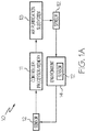
- FIG. 1 is a block diagram of an ECS 10 according to an exemplary embodiment of the present invention.
- the ECS 10 may include a controller 11, such as a computer having a processor and a memory, in continuous or intermittent communication with an air purification subsystem 13 and one or more sensors 12.
- the sensors 12 may be positioned in various points throughout the ECS to sense contaminants in, and/or air characteristics of, the outside air supplied through engine or APU bleeds or other air sources including ground supplies and electric compressors, and/or recirculating air in the ECS and/or, in particular, an environment 14, such an aircraft cabin.
- the contaminants in the ECS may include, for example, VOCs, SVOCs, ultrafine particles (UFPs), carbon monoxide, carbon dioxide, and ozone.
- One or more of the sensors 12 can be any sensor capable of sensing the anticipated contaminants in the contaminated air.
- One or more of the sensors can sense the identity and amount of the individual contaminants in the contaminant air.
- one or more sensors can sense the mass of the contaminants without regard to the specific identity of the individual contaminants.
- the sensor 12 may be a photoionization detector (PID), such as a PID, ppbRAE 3000, by RAE Systems of San Jose, CA.
- PID photoionization detector
- the sensor may also be a PID.
- one or more of the sensors 12 can be any sensor capable of sensing anticipated air characteristics, such as temperature and pressure or gas composition, of the contaminated air.
- anticipated air characteristics such as temperature and pressure or gas composition
- part numbers 51090026-51 and 1090030-51 by Honeywell for temperature and pressure sensors could be used.
- the controller 11 can include a processor and a memory that can store instructions to be executed by the processor to implement a method of removing contaminants from, and/or change air characteristics in, a space to be occupied by humans, such as the cabin of an aircraft, according to the present invention.
- the controller 11 may receive contamination signals from sensor(s) 12 which may sense contaminants from, for example, a cabin filter, a filter to a mix manifold 23, an ECS pack to the mix manifold 23, and the mix manifold 23 to the cabin.
- the controller 11 may also receive contamination signals from sensor(s) 12 which may sense contaminants in bleed air 22 coming from, for example, one or more engines and/or an auxiliary power unit (APU).
- the controller 11 may receive characteristic signals from sensor(s) 12 which may sense air characteristics from, for example, the cabin.
- the controller 11 may then compare the contamination signals and/or characteristic signals to one or more threshold signals that may relate to, for example, cabin pressure, cabin temperature, particulate mass and VOC concentrations.
- the controller 11 may compare contamination signals to a contaminant concentration look up table that may have information/data of contaminant concentration equivalents versus percentile of a sample database.
- the controller 11 may, in addition to or in lieu of the foregoing comparison, compare contamination signals to a contaminant mass look up table that may have information/data of total mass of contaminants versus percentile of a sample database that may or may not the be same sample database in look up table.
- the controller may compare air characteristic signals to a temperature look up table that may have information/data of temperature requirements in a cabin as promulgated by a government agency. A similar comparison may occur for the air characteristic of pressure in a cabin.
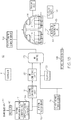
- FIG. 1B is an exemplary embodiment of the ECS 10 depicted in FIG.1A .
- the controller 11 may control one or more of the components and/or subsystems of the ECS 10.
- the ECS 10 may include a pneumatic bleed air precooler 17 that cools outside or bleed air 22 supplied through engine or APU bleeds or other air sources including ground supplies and electric compressors, entering the ECS 10.
- the outside air 22 supplied through engine or APU bleeds or other air sources including ground supplies and electric compressors may have contaminants that, at certain levels, may be undesirable for occupants in the environment 14.
- the pneumatic bleed air precooler 17 may be of any design well known in the art, such as a pneumatic bleed air precooler made by Honeywell International Inc.
- the pneumatic bleed air precooler 17 may cause a cooling in air temperature wherein the upon cooling the temperature of the air exiting the pneumatic bleed air precooler 16 can be, in embodiments, in a range of from about 135°C to about 260°C, or from about 135°C to about 200°C, or from about 135°C to about 150°C.
- a hydrocarbon and ozone converter 18 may receive air from the precooler 17 and convert hydrocarbons and ozone in the air to compounds that are believed to be non-harmful to humans.
- the converter 18 may be of any design well known in the art, such as an ozone converter made by Honeywell, part number 2341590-1, or a volatile organic compound and ozone converter made by Honeywell, part number 67200008-00.
- the converter 18 may convert a percentage of the total hydrocarbons wherein, in embodiments, the amount of hydrocarbons in the air exiting the converter 18 may be in a range of from about 0 ug/M3 to about 4000 ug/M3, or from about 0 ppmV to about 0.5 ppmV isobutylene equivalents, or from about 0 ug/M3 to about 500 ug/M3 isobutylene equivalents, or from about 0 ppmV isobutylene equivalents to about 0.1 ppmV isobutylene equivalents.
- the converter 18 may convert a percentage of the total ozone wherein the amount of ozone in the air existing the converter 18 may be, in embodiments, in a range of from about 0 ppmV to about 0.1 ppmV, or from about 0 ppmV to about 0.25 ppmV,.
- a particulate filter 19a may receive air from the converter 18 to filter out particulates of a desired size.
- the particulates exiting the filter 19a can be, in embodiments, of a size of from about 0 um to about 0.3 um for 99% HEPA filtration at 0.3 um.
- the filter 19a may be of any design well known in the art, such as a filter made by Honeywell SP Defense under the trade name FMM7TM.
- a particle sensor 12a may be downstream of the filter 19a to sense a particle count per cubic centimeter or contaminant mass concentration in the air flow control valve 13.
- the particle count concentration or mass contaminant concentration may be for one or more contaminants - for example, contaminants including but not limited to VOCs adhered to carbon and SVOC aerosol.
- the senor 12a may sense particle count or concentrations, in embodiments, of from about 0 particles/cm 3 to about 1,000,000 particles/cm 3 (for aircraft takeoff), or from about 0 particles/cm 3 to about 400,000 particles/cm 3 (for aircraft landing), or from about 0 particles/cm 3 to about 800,000 particles/cm 3 (for aircraft descent), or from about 0 particles/cm 3 to about 100,000 particles/cm 3 (for aircraft cruise) or a mass concentration of from about 0 ug/M3 to about 100,000 ug/M3, or from about 0 ug/M3 to about 4000 ug/M3, or from about 0 ug/M3 to about 500 ug/M3, or from about 250 ug/M3 to about 400 ug/M3.
- the sensor 12a may then send intermittent or continuous particle count or mass contaminant concentration signals to the controller 11, such as when the mass contaminant concentration exceeds/equals a threshold and/or falls below a threshold.
- a flow control valve 13 may be downstream of the sensor 12a to control the amount and/or rate of air from the filter 19a, to an air conditioning system 20, and eventually to an environment 14.
- the valve 13 may receive command signals from the controller 11 to alter the air flow amount or rate entering the air conditioning system 20.
- the valve 13 may change or meter a rate of air flow wherein, in embodiments, a flow rate is of from about 0 to about 5000 cubic feet per minute recirculation flow (for a large wide body aircraft), or from about 0 to about 2500 cubic feet per minute recirculation flow (for a narrow body aircraft), or from about 0 to about 300 M3 per hour for a single filter.
- the size and number of filters is changed to maintain filter face velocity within allowable filter performance requirements.
- the valve 13 may be of any design well known in the art, such as a 3.0 inch diameter electric motor modulating valve, part number 3205034-4, made by Honeywell.
- An air conditioning subsystem 20 may be downstream of the valve 13.
- the subsystem 20 may alter the temperature and/or pressure of the air from the valve 13, and may be, for example, Engine Bleed Air System, Pneumatic Air Distribution System, Honeywell PN 6217C000-016 might be used.
- the air exiting the subsystem 20 may have a temperature of from about -10°C to about 0°C, or from about 5 °C to about 27°C, or from about 15°C to about 25°C and mixed with hot bleed air 22 to obtain supply temperatures within about 18°C to about 29°C .
- the air exiting the subsystem 20 may have a pressure of from about 11 psia to about 15 psia, or from about 12 psia to about 15 psia, or from about 13 psia to about 15 psia.
- a mix manifold 23 may be downstream of the air conditioning subsystem 20.
- the manifold 23 can mix air from the air conditioning subsystem 20 and the cabin recirculation fan (such as a fan by Honeywell, part number 606772-1) and distribute it to the cabin 14.
- the hot trim air (bleed air) 22 controlled by a valve (such as a 2 inch diameter trim air valve by Honeywell, part number 3291978-00), can be inserted into the cool air from the mix manifold 23 prior to entering the cabin to control air temperature within a range of from about 18°C to about 29°C (for normal aircraft operating conditions), or from about 15°C to about 20°C (to precool the cabin), or from about 30°C to about 40°C (to pre-heat the cabin).
- the ratio of volume of outside air 22 supplied through engine or APU bleeds or other air sources including ground supplies and electric compressors, to volume of recirculated air 21 may be, in embodiments, of from about 60 to about 100% (in normal aircraft operation), or from about 0% (if there was an adverse contamination event outside the aircraft, such as aircraft de-icing) to about 100%.
- the manifold 23 may be of any design well known in the art, such as a manifold made by Triumph Group.
- a sensor 12d such as a VOC sensor, may be downstream of the mix manifold 23. Although referred to as a VOC sensor, the sensor 12d is not intended to be limited to VOCs, but may also sense a combination of VOCs and SVOCs as an example.
- the sensor 12d may sense concentrations of one or more contaminants to verify that the mixed air exiting the manifold 23 meets certain requirements for occupant comfort in the environment 14.
- the requirements may be government regulatory requirements that address maximum limits for, example, CO, CO2, ozone, VOC, SVOC, and particulates. In other words, the maximum limits can be thresholds that should not be exceeded.
- the senor 12d may sense contaminant concentrations, in embodiments, of from about 0 ppmV to about 1 ppmV, or from about 0 ug/M3 to about 4000 ug/M3, or from about 0 UFP/cm3 to about 500,000 UFP/cm3.
- the sensor 12d may then send intermittent and/or continuous concentration contamination signals to the controller 11, particularly when the contaminant concentration exceeds/equals a threshold and/or falls below a threshold.
- the mixed air from the manifold 23 may enter the environment 14 where additional contaminants may be added to the air.
- the additional contaminants may come from occupants in the environment 14.
- One or more sensors 12e may be within the environment 14 to sense air characteristics, such as temperature and/or pressure, of the mixed air in the environment 14.
- the sensor(s) 12e may verify that the mixed air meets certain requirements, such as government regulatory requirements, or does not exceed maximum limits, for occupant comfort in the environment 14.
- the maximum limits can be thresholds that should not be exceeded.
- a sensor 12e may sense temperature, in embodiments, of from about 18°C to about 29°C.
- a sensor 12e may sense pressure, in embodiments, of from about 11 psia to about 15 psia, or from about 12psia to about 15 psia, or from about 13 psia to about 15 psia.
- the sensor(s) 12e may then send intermittent and/or continuous air characteristic signals to the controller 11, particularly when one or more characteristics exceed/equal one or more thresholds and/or fall below one or more thresholds.
- Recirculated air 21 from the environment 14 may then exit to a filter 19c, which may be a high efficiency particulate absorption (HEPA) filter of any design well known in the art, such as a filter made by I Honeywell under the trade name FMM7.
- the filter 19a may remove particulates from the recirculated air 21 of a desired size, such as, in embodiments, particulates of a size of from about 0 um to about 0.3um at 99% removal efficiency.
- a recirculation fan 15 may be downstream of the filter 19c to modulate the flow of recirculation air 21 inversely with outside air 22 supplied through engine or APU bleeds or other air sources including ground supplies and electric compressors, and thereby maintain a ventilation rate of the recirculation air 21 exiting the environment 14.
- a ventilation rate may be in embodiments of from about 0 to about 5000 CFM for total recirculation flow (for a large wide body aircraft), or from about 0 to about 2500 CFM (for a narrow body aircraft), or sufficient filter area to maintain about 400 feet per minute filter face velocity.
- the fan 15 may be of any design well known in the art, such as a fan made by Honeywell, part number 606772-1.
- a recirculation filter 19b may be downstream of the fan 15.
- the filter 19b may remove particulates from the recirculated air 21 of a desired size, such as, in embodiments, particulates of a size of from about 0 to about 0.3 um at 99% removal efficiency, or from about 0 to about 1 um at 97% efficiency, or from about 0 to about 2.5 um for non-HEPA filtration.
- the filter 19b may be of any design well known in the art, such as a filter made by Honeywell under the trade name FMM7.
- a sensor 12b such as a VOC sensor, may be downstream of the filer 19b.
- the sensor 12b may sense concentrations of one or more VOCs in the recirculated air 21.
- the sensor 12b is not intended to be limited to VOCs, but may also sense SVOCs.
- the sensor 12b may sense VOC contaminant concentrations from about 0 ppmV to about 1 ppmV, or from about 0 ug/M3 to about 4 ug/M3, or from about 0 UFP/CM3 to about 500,000 UFP/CM3.
- the sensor 12b may then send a VOC concentration contamination signal to the controller 11.
- a sensor 12c such as a carbon dioxide sensor, may be downstream of the sensor 12b.
- the sensor 12c may sense concentration of carbon dioxide in the recirculated air 21.
- the sensor 12c may sense carbon dioxide contaminant concentrations, in embodiments, of from about background (about 400 ppmV) to about 5000 ppmV, or from about 800 ppmV to about 2000 ppmV, or from about 800 ppmV to about 1500 ppmV.
- the sensor 12c may then send intermittent and/or continuous carbon dioxide concentration contamination signals to the controller 11, particularly when a carbon dioxide concentration exceeds/equals a threshold and/or falls below a threshold. Downstream of the sensor 12c is the mix manifold 23.
- the ECS 10 adapts to changing contaminants and/or particulates and/or air characteristics in both the outside air 22 supplied through engine or APU bleeds or other air sources including ground supplies and electric compressors, and recirculated air 21.
- the changes can occur as an aircraft moves from one operating mode to another, such as from taxing, to takeoff, to cruise at, for example, about 35,000 feet.
- the ECS 10 adapts to the change by receiving intermittent and/or continuous signals from sensors, such as sensors 12a, 12b, 12c, 12d, and 12e. These signals can be generated when a parameter exceeds/equals a threshold and/or falls below a threshold.
- the controller 11 may command a change to the operation of the flow control valve 13, the air conditioning subsystem 20, the mix manifold 23, and/or recirculation fan 15.
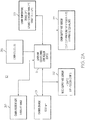
- FIG. 2A is a flow chart of how a controller, such as controller 11, may monitor sensors and command operating changes to the ECS components as contaminants and/or particulates and/or air characteristics change in the ECS.
- the air characteristics depicted in FIG. 2A e.g., carbon pressure, cabin temperature, etc.
- the air characteristics depicted in FIG. 2A may be altered by altering/changing one or more operating characteristics/parameters of the ECS components described above (e.g., manifold ratio, flow rate, ventilation rate, etc.). Accordingly, the combination of operating characteristics/parameters of the ECS components are not mere design choices.
- the controller 11 may control pressure 30 in the cabin 14 as the cabin 14 (i.e., aircraft) moves between, for example, 0 to 35,000 feet in altitude - going from taxi to cruise and then to landing.
- the controller 11 may decrease pressure 30 as the cabin changes altitude.
- the controller 11 may maintain the cabin pressure 30, in embodiments, of from about 11 psia to about 15 psia, which may be equivalent to what an occupant might experience outside of the cabin between 0 to 8000 feet.
- the controller 11 may, in embodiments, control carbon dioxide concentration 31 outside of the cabin 14 such that the concentration does not exceed about 5000ppm. Accordingly, in an exemplary embodiment, if the carbon dioxide concentration in the recirculated air reaches about 2000ppm, the controller 11 may command that an outside air 22 inflow rate be increased. In another exemplary embodiment, if the carbon dioxide concentration in the recirculated air falls below about 800ppm, the controller 11 may command that an outside air 22 flow inflow be decreased.
- the controller 11 may control cabin temperature 33 in the cabin 14. For example, during cruise of the aircraft, the cabin temperature 33 may have a threshold at about 24°C; while on the ground, the cabin temperature may have a threshold of no more than about 27°C; with a temperature variation at all times being less than about 5°C. These temperatures may be maintained by the controller 11 commanding a change in the air conditioning subsystem 20, for example, by decreasing trim air 16 from the hot system, or increasing the cold air from the air cycle machine 20 to maintain the temperature set-point.
- the controller 11 may control bleed air VOCs 32 into the cabin 14.
- the bleed air 22 may be from one or more aircraft engines and/or an APU.
- a particle sensor such as sensor 12a, may have an ultra-fine particle count threshold of about 200,000 to 250,000 UFP/cm3.
- the controller 11 may command the manifold 23 to reduce the bleed air 22, increase the recirculation air 21, and send a note to the flight maintenance system to recommend further evaluation.
- the controller 11 may control cabin supply air VOCs 34 coming from the manifold 23 and into the cabin 14.
- VOC sensors i.e., contaminant sensors for VOCs and other contaminants
- VOC sensors may have, in some embodiments, a threshold of about 0.047 to 0.067 ppm isobutylene equivalents. Isobutylene equivalents are contaminant concentrations converted to a reference compound concentration by a given sensor, and further described in US patent application entitled "Human Factors Approach to Control Contaminant Concentrations in Aircraft Supply Air from Engine Bleed and Ground Sources, and in Recirculated Air Being Delivered to Aircraft Cabins for the Optimization of User Experience and Energy Consumption," filed concurrently with this application and incorporated herein by reference in its entirety.
- the VOC sensors may have, in some embodiments, a threshold of about 0-9 ppm carbon dioxide equivalents.
- VOC sensors may monitor VOCs and other compounds upstream and downstream of air purification filters, such as filters 19b and 19c. In other embodiments, VOC sensors may monitor VOCs and other compounds at the exit of a mix manifold, such as manifold 23
- the controller 11 may control carbon monoxide, carbon dioxide, and/or ozone in the cabin 14 through the use of one or more sensors.
- a carbon monoxide threshold may be from about or 9 ppmV (the US EPA recommended limit) to about 50 ppmV (the FAA maximum allowed)
- a carbon dioxide threshold may be from about 800 ppmV to -2000 ppmV (but not to exceed 5000 ppmV, the FAA limit)
- an ozone threshold may be from about 0.1 ppmV to about 0.25 ppmV (for short durations). ---.
- the controller 11 may command the manifold to increase bleed air 22, according to various embodiments.
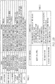
- FIG. 2B is a table depicting control logic that may be executed by the controller 11 in embodiments of the present invention.
- Table 1 of FIG. 2B identifies in the first column the sensor in question, in the second column the signal sent by the sensor, and in the third column the response or command by the controller 11 upon receipt of the signal. It can be seen that in the example of Table 1, the signal is either above or below a target or threshold.
- the present invention contemplates that there can be more than one threshold that triggers the sending of a signal. For example, at above first threshold, a first signal may be sent to the controller 11. At below a second threshold, which is lower than the first threshold, a second signal may be sent to the controller 11.
- the respective response/command in this exemplary embodiment, is in many instances an increase or decrease in bleed air.
- the present invention contemplates that other responses/commands may occur.
- Table 2 includes a first column that identifies control function (i.e., the ECS component being controlled or commanded), while the second column identifies the respective controller logic or commands.
- control function i.e., the ECS component being controlled or commanded
- second column identifies the respective controller logic or commands.
- the components being controlled and the respective commands are exemplary and others can be within the scope of the present invention.
- fuel consumption by an aircraft for example, can be reduced by about 0.5 to 1.5%.
Landscapes
- Health & Medical Sciences (AREA)
- General Health & Medical Sciences (AREA)
- Pulmonology (AREA)
- Engineering & Computer Science (AREA)
- Aviation & Aerospace Engineering (AREA)
- Air Conditioning Control Device (AREA)
Claims (8)
- Système (10) de régulation environnementale (ECS) servant à éliminer des contaminants dans de l'air d'alimentation qui entre dans un environnement (14), comportant :un capteur (12a) de contaminants d'air extérieur qui détecte des contaminants dans un air extérieur qui constitue une partie des contaminants dans l'air d'alimentation ;un capteur (12b) de contaminants d'air recyclé qui détecte des contaminants dans un air recyclé (21) qui constitue une autre partie des contaminants dans l'air d'alimentation, l'air recyclé (21) étant fourni par l'environnement (14), un capteur (12e) de pression qui détecte la pression de l'air d'alimentation dans l'environnement (14), un capteur (12e) de température qui détecte la température de l'air d'alimentation dans l'environnement (14), un capteur (12c) de dioxyde de carbone qui détecte du dioxyde de carbone dans l'air recyclé (21) quittant l'environnement, un régulateur (11) ;l'air extérieur étant fourni par l'intermédiaire de prélèvements (22) de moteur ou d'APU ou d'autres sources d'air incluant des alimentations au sol et des compresseurs électriques, ou en recyclant de l'air dans l'ECS ;le capteur de contaminants d'air extérieur se trouvant en amont de l'environnement (14) ;le capteur de contaminants d'air recyclé se trouvant en aval de l'environnement (14) ;le capteur (12e) de pression étant situé dans l'environnement (14) ;le capteur (12e) de température étant situé dans l'environnement (14) ;le capteur (12c) de dioxyde de carbone se trouvant en aval de l'environnement (14) ; etle régulateur (11) étant en communication continue avec le capteur (12a) de contaminants d'air extérieur, le capteur (12b) de contaminants d'air recyclé, le capteur (12e) de pression, le capteur (12e) de température, et le capteur (12c) de dioxyde de carbone ;le régulateur (11) commandant, suite à la réception d'un signal de seuil en provenance d'un des capteurs, un flux entrant de l'air extérieur fourni par l'intermédiaire de la source extérieure à l'ECS (10) qui se mélange à l'air recyclé (21) ;l'ECS étant caractérisé en ce que :
le régulateur (11) est configuré pour comparer des signaux de contamination à une table de consultation de concentrations de contaminant qui comprend des données de équivalents de concentration de contaminant vis-à-vis du percentile de population d'une base de données d'échantillons. - ECS (10) selon la revendication 1, le capteur (12a) de contaminants d'air extérieur comportant un capteur de particules ultrafines.
- ECS (10) selon l'une quelconque des revendications 1 à 2, le capteur (12a) de contaminants d'air extérieur comportant un capteur de composés organiques volatils.
- ECS (10) selon l'une quelconque des revendications 1 à 3, le capteur (12b) de contaminants d'air recyclé comportant un capteur de composés organiques volatils.
- ECS (10) selon l'une quelconque des revendications 1 à 4, le capteur (12c) de dioxyde de carbone se trouvant en aval du capteur (12b) de contaminants d'air recyclé.
- ECS (10) selon l'une quelconque des revendications 1 à 5, comportant en outre un pré-refroidisseur (16) en amont du capteur (12a) de contaminants d'air extérieur.
- ECS (10) selon l'une quelconque des revendications 1 à 6, comportant en outre un sous-système (20) de climatisation en amont de l'environnement (14).
- ECS (10) selon l'une quelconque des revendications 1 à 7, comportant en outre un collecteur (23) de mélange en amont de l'environnement (14).
Applications Claiming Priority (1)
| Application Number | Priority Date | Filing Date | Title |
|---|---|---|---|
| US14/606,315 US9957052B2 (en) | 2015-01-27 | 2015-01-27 | Aircraft environmental control system that optimizes the proportion of outside air from engines, APU's, ground air sources and the recirculated cabin air to maintain occupant comfort and maximize fuel economy |
Publications (2)
| Publication Number | Publication Date |
|---|---|
| EP3050801A1 EP3050801A1 (fr) | 2016-08-03 |
| EP3050801B1 true EP3050801B1 (fr) | 2019-06-26 |
Family
ID=55236258
Family Applications (1)
| Application Number | Title | Priority Date | Filing Date |
|---|---|---|---|
| EP16152656.1A Active EP3050801B1 (fr) | 2015-01-27 | 2016-01-25 | Système de commande environnementale d'aéronef qui optimise la proportion de l'air extérieur à partir des moteurs, apu, sources d'air au sol et de l'air de la cabine remis en circulation pour maintenir le confort des occupants et maximiser l'économie de carburant |
Country Status (2)
| Country | Link |
|---|---|
| US (1) | US9957052B2 (fr) |
| EP (1) | EP3050801B1 (fr) |
Cited By (1)
| Publication number | Priority date | Publication date | Assignee | Title |
|---|---|---|---|---|
| US11434010B2 (en) | 2019-02-08 | 2022-09-06 | Hamilton Sundstrand Corporation | Environmental control systems and methods of controlling airflow through environmental control systems |
Families Citing this family (49)
| Publication number | Priority date | Publication date | Assignee | Title |
|---|---|---|---|---|
| US10287021B2 (en) * | 2015-03-12 | 2019-05-14 | C&D Zodiac, Inc. | Fragrance delivery system |
| US10913539B2 (en) | 2015-03-12 | 2021-02-09 | Safran Cabin Inc. | Fragrance delivery system |
| US10895523B2 (en) * | 2015-04-30 | 2021-01-19 | The University Of Connecticut | Method of optimal sensor selection and fusion for heat exchanger fouling diagnosis in aerospace systems |
| US10703488B2 (en) * | 2015-05-22 | 2020-07-07 | Bombardier Inc. | Aircraft air quality monitoring system and method |
| EP3297917B1 (fr) | 2015-05-22 | 2023-10-04 | Bombardier Inc. | Gestion de la circulation d'air dans cabine d'aéronef |
| US10954858B2 (en) * | 2015-06-18 | 2021-03-23 | Hamilton Sunstrand Corporation | Plate fin heat exchanger |
| CN108025618A (zh) * | 2015-08-03 | 2018-05-11 | 爱科国际有限公司 | 用于处理车辆驾驶室用的空气的系统和方法 |
| US9884281B2 (en) * | 2015-09-18 | 2018-02-06 | Honeywell International Inc. | Method to use ultrafine particulate matter detection and measurement to control air supply system contaminant delivery to the aircraft cabin environment |
| US10377498B2 (en) * | 2016-01-21 | 2019-08-13 | The Boeing Company | Aircraft and associated method for providing electrical energy to an anti-icing system |
| DE102016201924A1 (de) * | 2016-02-09 | 2017-08-10 | Lufthansa Technik Aktiengesellschaft | Flugzeug und Warneinrichtung für ein "Engine Oil Smell" in einer Flugzeugkabine eines Flugzeuges |
| US10650621B1 (en) | 2016-09-13 | 2020-05-12 | Iocurrents, Inc. | Interfacing with a vehicular controller area network |
| US10329022B2 (en) * | 2016-10-31 | 2019-06-25 | Honeywell International Inc. | Adjustable sensor or sensor network to selectively enhance identification of select chemical species |
| EP3323728B1 (fr) * | 2016-11-21 | 2019-01-02 | Airbus Operations GmbH | Système et procédé permettant de déterminer l'origine d'une fuite d'huile dans un système d'alimentation en air |
| DE102017101014A1 (de) | 2017-01-19 | 2018-07-19 | Testo SE & Co. KGaA | Verfahren und Vorrichtung zur Überwachung von Umgebungsbedingungen innerhalb eines Transportmittels |
| US10427797B2 (en) * | 2017-01-20 | 2019-10-01 | Honeywell International Inc. | Systems and methods for reducing environmental control system maintenance |
| US10384785B2 (en) | 2017-02-17 | 2019-08-20 | Hamilton Sundstrand Corporation | Two mode system that provides bleed and outside air or just outside air |
| US11177102B2 (en) * | 2017-05-05 | 2021-11-16 | Astronics Advanced Electronic Systems Corp. | Volatile organic compound controlled relay for power applications |
| US10618660B2 (en) * | 2017-11-20 | 2020-04-14 | The Boeing Company | Systems and methods providing airflow to a flight deck |
| US10703491B2 (en) * | 2017-11-28 | 2020-07-07 | Hamilton Sunstrand Corporation | Aircraft cabin air monitor |
| DE102017128338A1 (de) * | 2017-11-29 | 2019-05-29 | Airbus Operations Gmbh | Klimatisierungssystem für ein Luftfahrzeug |
| US11566801B2 (en) * | 2018-01-02 | 2023-01-31 | Arizona Board Of Regents On Behalf Of Arizona State University | Method and system for assessing metabolic rate and maintaining indoor air quality and efficient ventilation energy use with passive environmental sensors |
| US11465755B1 (en) * | 2018-04-30 | 2022-10-11 | United States Of America As Represented By The Secretary Of The Air Force | Aircraft air quality testing system |
| EP3587267A1 (fr) | 2018-06-29 | 2020-01-01 | United Technologies Research Centre Ireland | Système de conditionnement d'air |
| US10710741B2 (en) | 2018-07-02 | 2020-07-14 | Joby Aero, Inc. | System and method for airspeed determination |
| US11344863B2 (en) | 2018-07-09 | 2022-05-31 | The Boeing Company | Systems, devices and methods for regeneration of a sorbent |
| WO2020061085A1 (fr) | 2018-09-17 | 2020-03-26 | Joby Aero, Inc. | Système de commande d'aéronef |
| US10983534B2 (en) | 2018-12-07 | 2021-04-20 | Joby Aero, Inc. | Aircraft control system and method |
| EP3935581A4 (fr) | 2019-03-04 | 2022-11-30 | Iocurrents, Inc. | Compression et communication de données à l'aide d'un apprentissage automatique |
| US11230384B2 (en) * | 2019-04-23 | 2022-01-25 | Joby Aero, Inc. | Vehicle cabin thermal management system and method |
| KR102806907B1 (ko) | 2019-04-23 | 2025-05-13 | 조비 에어로, 인크. | 배터리 열 관리 시스템 및 방법 |
| US11780609B2 (en) | 2019-06-12 | 2023-10-10 | Honeywell International Inc. | Maintenance recommendations using lifecycle clustering |
| EP3760854B1 (fr) * | 2019-07-01 | 2023-05-24 | Airbus Operations, S.L.U. | Système de gestion de l'air |
| US11554634B2 (en) * | 2019-10-01 | 2023-01-17 | The Boeing Company | Vehicle air handling system for apportioning airflow between passenger and cargo compartments |
| EP3808658B1 (fr) * | 2019-10-14 | 2024-07-31 | Hamilton Sundstrand Corporation | Système de contrôle environnemental |
| EP3808659B1 (fr) | 2019-10-16 | 2022-11-30 | Hamilton Sundstrand Corporation | Système de gestion d'emballage pour système de contrôle environnemental |
| EP3845289A1 (fr) * | 2019-12-31 | 2021-07-07 | Hamilton Sundstrand Corporation | Système de climatisation d'un aéronef |
| CN111268141B (zh) * | 2020-02-28 | 2021-02-19 | 南京航空航天大学 | 飞机高温消毒灭菌空调系统及消毒灭菌方法 |
| US11643215B2 (en) * | 2020-06-09 | 2023-05-09 | Honeywell International Inc. | Use of carbon dioxide sensors for aircraft ventilation control |
| US11981436B2 (en) * | 2020-06-10 | 2024-05-14 | B/E Aerospace, Inc. | Personal aircraft seat air treatment system |
| US12179926B2 (en) * | 2020-06-19 | 2024-12-31 | The Boeing Company | Methods and systems for decontaminating aircraft cabins and providing indications for safe reentry |
| US11851205B2 (en) * | 2020-07-06 | 2023-12-26 | Honeywell International Inc. | Air quality monitoring |
| US11635312B2 (en) * | 2020-07-06 | 2023-04-25 | Honeywell International Inc. | Systems and methods for remote sensor calibration |
| US11780590B2 (en) * | 2020-08-14 | 2023-10-10 | Honeywell International Inc. | Aircraft cabin disinfection |
| US12298789B2 (en) * | 2020-11-06 | 2025-05-13 | Hamilton Sundstrand Corporation | Digitally augmented pneumatic control |
| DE102020135075A1 (de) | 2020-12-29 | 2022-06-30 | Malte SCHWARZE | Kohlenstoffdioxid-Detektion in Fahrzeugen, Passagier- und Frachträumen |
| US11893834B2 (en) | 2021-01-27 | 2024-02-06 | Honeywell International Inc. | Supply air contamination detection |
| US12098984B2 (en) * | 2021-04-02 | 2024-09-24 | Honeywell International Inc. | Supply air contamination sensor |
| US20240308669A1 (en) * | 2023-03-17 | 2024-09-19 | Hamilton Sundstrand Corporation | Energy recovery and thermal control utilizing heat pump |
| WO2025080731A2 (fr) * | 2023-10-09 | 2025-04-17 | Aeroparts Manufacturing & Repair, Inc. | Procédés d'épuration d'air de cabine et d'air de prélèvement réacteur dans un système de contrôle environnemental d'un aéronef |
Family Cites Families (20)
| Publication number | Priority date | Publication date | Assignee | Title |
|---|---|---|---|---|
| US4742761A (en) | 1987-07-20 | 1988-05-10 | The Boeing Company | Method and apparatus for controlling the concentration of carbon dioxide in an aircraft cabin |
| US4966005A (en) * | 1989-12-12 | 1990-10-30 | Allied-Signal Inc. | Advanced hybrid air/vapor cycle ECS |
| DE4436938A1 (de) | 1994-04-27 | 1996-04-18 | Auto Electronics Corp | Nässe- und windgeschützter Gassensor |
| JP2000510231A (ja) | 1996-03-27 | 2000-08-08 | アライドシグナル・インコーポレーテッド | 空気汚染物質モニター装置 |
| US6711470B1 (en) | 2000-11-16 | 2004-03-23 | Bechtel Bwxt Idaho, Llc | Method, system and apparatus for monitoring and adjusting the quality of indoor air |
| US6526775B1 (en) * | 2001-09-14 | 2003-03-04 | The Boeing Company | Electric air conditioning system for an aircraft |
| ATE500501T1 (de) | 2003-12-29 | 2011-03-15 | Airbus Operations Gmbh | Olfaktorische methode zur bestimmung der quantitativen und qualitativen geruchseigenschaften in einem luftstrom |
| US7122065B2 (en) | 2004-02-25 | 2006-10-17 | Honeywell International, Inc. | Adapter for low volume air sampler |
| US7089747B2 (en) | 2004-02-27 | 2006-08-15 | Honeywell International, Inc. | Pressure reduction apparatus and method |
| US7803039B2 (en) | 2004-06-18 | 2010-09-28 | Denso Corporation | Method of controlling air intake into air conditioned enclosure |
| US7833305B1 (en) | 2005-04-19 | 2010-11-16 | Studer Ronald M | Filter device |
| US20070084938A1 (en) * | 2005-10-18 | 2007-04-19 | Mingsheng Liu | Variable single zone air volume control system and method |
| JP5519294B2 (ja) | 2007-01-10 | 2014-06-11 | コーニンクレッカ フィリップス エヌ ヴェ | 空調システムを制御するための制御システム |
| GB2447042B (en) * | 2007-02-27 | 2011-11-09 | Building Res Establishment Ltd | Apparatus and method for air sampling |
| US7871038B2 (en) * | 2007-05-17 | 2011-01-18 | The Boeing Company | Systems and methods for providing airflow in an aerospace vehicle |
| US20090084896A1 (en) * | 2007-09-27 | 2009-04-02 | Hamilton Sundstrand Corporation | Cabin air system for aviation electronics |
| DE102009017932B4 (de) | 2009-04-20 | 2010-12-09 | Gröger & Obst Vertriebs- und Service GmbH | Verfahren zur kontinuierlichen quantitativen Bestimmung einer oxidierbaren chemischen Verbindung in einem Untersuchungsmedium |
| KR20110127337A (ko) | 2010-05-19 | 2011-11-25 | 우리산업 주식회사 | 자동차의 실내공기질 센싱 및 제어장치 |
| GB201112736D0 (en) | 2011-07-25 | 2011-09-07 | Building Res Establishment Ltd | Apparatus and method for air monitoring |
| US9889939B2 (en) | 2012-06-06 | 2018-02-13 | The Boeing Company | Environmental control system and methods of operating same |
-
2015
- 2015-01-27 US US14/606,315 patent/US9957052B2/en active Active
-
2016
- 2016-01-25 EP EP16152656.1A patent/EP3050801B1/fr active Active
Non-Patent Citations (1)
| Title |
|---|
| None * |
Cited By (1)
| Publication number | Priority date | Publication date | Assignee | Title |
|---|---|---|---|---|
| US11434010B2 (en) | 2019-02-08 | 2022-09-06 | Hamilton Sundstrand Corporation | Environmental control systems and methods of controlling airflow through environmental control systems |
Also Published As
| Publication number | Publication date |
|---|---|
| EP3050801A1 (fr) | 2016-08-03 |
| US9957052B2 (en) | 2018-05-01 |
| US20160214723A1 (en) | 2016-07-28 |
Similar Documents
| Publication | Publication Date | Title |
|---|---|---|
| EP3050801B1 (fr) | Système de commande environnementale d'aéronef qui optimise la proportion de l'air extérieur à partir des moteurs, apu, sources d'air au sol et de l'air de la cabine remis en circulation pour maintenir le confort des occupants et maximiser l'économie de carburant | |
| EP3315410B1 (fr) | Capteur réglable ou réseau de capteurs pour améliorer de manière sélective l'identification d'espèces chimiques choisies | |
| US9902499B2 (en) | Human factors approach to control contaminant concentrations in aircraft supply air from engine and APU bleed air and ground air sources, and in recirculated air being delivered to aircraft cabins for the optimization of user experience and energy consumption | |
| US9884281B2 (en) | Method to use ultrafine particulate matter detection and measurement to control air supply system contaminant delivery to the aircraft cabin environment | |
| CN107635875B (zh) | 飞行器的机舱中的气流管理 | |
| EP3297918B1 (fr) | Système et procédé de surveillance de la qualité de l'air d'un aéronef | |
| Michaelis et al. | Ultrafine particle levels measured on board short-haul commercial passenger jet aircraft | |
| US20200002009A1 (en) | Methodology that regulates the system components and optimizes the mixing of outside air in an adaptive environmental control system | |
| EP3296207B1 (fr) | Procédé permettant de détecter et mesurer une matière particulaire ultrafine afin de contrôler la distribution d'un contaminant dans un système d'alimentation en air dans l'environnement d'une cabine d'avion | |
| Tao et al. | Studies on new air purification and air quality control system of airliner cabin | |
| Stichternath | Pilot Measures against Cabin Air Contamination | |
| Lakies | Dynamic Cabin Air Contamination Calculation Theory | |
| Eden | The air we breathe | |
| WO2026072026A2 (fr) | Système de détection de contaminants d'air de prélèvement d'aéronef | |
| Lakies | Supervisor: Prof. Dr.-Ing. Dieter Scholz, MSME Submitted: 2019-03-01 | |
| Haney et al. | Monitoring of potential bleed air gas contaminants with FTIR spectroscopy |
Legal Events
| Date | Code | Title | Description |
|---|---|---|---|
| PUAI | Public reference made under article 153(3) epc to a published international application that has entered the european phase |
Free format text: ORIGINAL CODE: 0009012 |
|
| 17P | Request for examination filed |
Effective date: 20160125 |
|
| AK | Designated contracting states |
Kind code of ref document: A1 Designated state(s): AL AT BE BG CH CY CZ DE DK EE ES FI FR GB GR HR HU IE IS IT LI LT LU LV MC MK MT NL NO PL PT RO RS SE SI SK SM TR |
|
| AX | Request for extension of the european patent |
Extension state: BA ME |
|
| STAA | Information on the status of an ep patent application or granted ep patent |
Free format text: STATUS: EXAMINATION IS IN PROGRESS |
|
| 17Q | First examination report despatched |
Effective date: 20180726 |
|
| GRAP | Despatch of communication of intention to grant a patent |
Free format text: ORIGINAL CODE: EPIDOSNIGR1 |
|
| STAA | Information on the status of an ep patent application or granted ep patent |
Free format text: STATUS: GRANT OF PATENT IS INTENDED |
|
| INTG | Intention to grant announced |
Effective date: 20190215 |
|
| GRAS | Grant fee paid |
Free format text: ORIGINAL CODE: EPIDOSNIGR3 |
|
| GRAA | (expected) grant |
Free format text: ORIGINAL CODE: 0009210 |
|
| STAA | Information on the status of an ep patent application or granted ep patent |
Free format text: STATUS: THE PATENT HAS BEEN GRANTED |
|
| AK | Designated contracting states |
Kind code of ref document: B1 Designated state(s): AL AT BE BG CH CY CZ DE DK EE ES FI FR GB GR HR HU IE IS IT LI LT LU LV MC MK MT NL NO PL PT RO RS SE SI SK SM TR |
|
| REG | Reference to a national code |
Ref country code: GB Ref legal event code: FG4D |
|
| REG | Reference to a national code |
Ref country code: CH Ref legal event code: EP |
|
| REG | Reference to a national code |
Ref country code: AT Ref legal event code: REF Ref document number: 1148004 Country of ref document: AT Kind code of ref document: T Effective date: 20190715 |
|
| REG | Reference to a national code |
Ref country code: IE Ref legal event code: FG4D |
|
| REG | Reference to a national code |
Ref country code: DE Ref legal event code: R096 Ref document number: 602016015764 Country of ref document: DE |
|
| REG | Reference to a national code |
Ref country code: NL Ref legal event code: MP Effective date: 20190626 |
|
| PG25 | Lapsed in a contracting state [announced via postgrant information from national office to epo] |
Ref country code: AL Free format text: LAPSE BECAUSE OF FAILURE TO SUBMIT A TRANSLATION OF THE DESCRIPTION OR TO PAY THE FEE WITHIN THE PRESCRIBED TIME-LIMIT Effective date: 20190626 Ref country code: SE Free format text: LAPSE BECAUSE OF FAILURE TO SUBMIT A TRANSLATION OF THE DESCRIPTION OR TO PAY THE FEE WITHIN THE PRESCRIBED TIME-LIMIT Effective date: 20190626 Ref country code: HR Free format text: LAPSE BECAUSE OF FAILURE TO SUBMIT A TRANSLATION OF THE DESCRIPTION OR TO PAY THE FEE WITHIN THE PRESCRIBED TIME-LIMIT Effective date: 20190626 Ref country code: LT Free format text: LAPSE BECAUSE OF FAILURE TO SUBMIT A TRANSLATION OF THE DESCRIPTION OR TO PAY THE FEE WITHIN THE PRESCRIBED TIME-LIMIT Effective date: 20190626 Ref country code: FI Free format text: LAPSE BECAUSE OF FAILURE TO SUBMIT A TRANSLATION OF THE DESCRIPTION OR TO PAY THE FEE WITHIN THE PRESCRIBED TIME-LIMIT Effective date: 20190626 Ref country code: NO Free format text: LAPSE BECAUSE OF FAILURE TO SUBMIT A TRANSLATION OF THE DESCRIPTION OR TO PAY THE FEE WITHIN THE PRESCRIBED TIME-LIMIT Effective date: 20190926 |
|
| REG | Reference to a national code |
Ref country code: LT Ref legal event code: MG4D |
|
| PG25 | Lapsed in a contracting state [announced via postgrant information from national office to epo] |
Ref country code: RS Free format text: LAPSE BECAUSE OF FAILURE TO SUBMIT A TRANSLATION OF THE DESCRIPTION OR TO PAY THE FEE WITHIN THE PRESCRIBED TIME-LIMIT Effective date: 20190626 Ref country code: LV Free format text: LAPSE BECAUSE OF FAILURE TO SUBMIT A TRANSLATION OF THE DESCRIPTION OR TO PAY THE FEE WITHIN THE PRESCRIBED TIME-LIMIT Effective date: 20190626 Ref country code: GR Free format text: LAPSE BECAUSE OF FAILURE TO SUBMIT A TRANSLATION OF THE DESCRIPTION OR TO PAY THE FEE WITHIN THE PRESCRIBED TIME-LIMIT Effective date: 20190927 Ref country code: BG Free format text: LAPSE BECAUSE OF FAILURE TO SUBMIT A TRANSLATION OF THE DESCRIPTION OR TO PAY THE FEE WITHIN THE PRESCRIBED TIME-LIMIT Effective date: 20190926 |
|
| REG | Reference to a national code |
Ref country code: AT Ref legal event code: MK05 Ref document number: 1148004 Country of ref document: AT Kind code of ref document: T Effective date: 20190626 |
|
| PG25 | Lapsed in a contracting state [announced via postgrant information from national office to epo] |
Ref country code: NL Free format text: LAPSE BECAUSE OF FAILURE TO SUBMIT A TRANSLATION OF THE DESCRIPTION OR TO PAY THE FEE WITHIN THE PRESCRIBED TIME-LIMIT Effective date: 20190626 Ref country code: PT Free format text: LAPSE BECAUSE OF FAILURE TO SUBMIT A TRANSLATION OF THE DESCRIPTION OR TO PAY THE FEE WITHIN THE PRESCRIBED TIME-LIMIT Effective date: 20191028 Ref country code: SK Free format text: LAPSE BECAUSE OF FAILURE TO SUBMIT A TRANSLATION OF THE DESCRIPTION OR TO PAY THE FEE WITHIN THE PRESCRIBED TIME-LIMIT Effective date: 20190626 Ref country code: RO Free format text: LAPSE BECAUSE OF FAILURE TO SUBMIT A TRANSLATION OF THE DESCRIPTION OR TO PAY THE FEE WITHIN THE PRESCRIBED TIME-LIMIT Effective date: 20190626 Ref country code: CZ Free format text: LAPSE BECAUSE OF FAILURE TO SUBMIT A TRANSLATION OF THE DESCRIPTION OR TO PAY THE FEE WITHIN THE PRESCRIBED TIME-LIMIT Effective date: 20190626 Ref country code: EE Free format text: LAPSE BECAUSE OF FAILURE TO SUBMIT A TRANSLATION OF THE DESCRIPTION OR TO PAY THE FEE WITHIN THE PRESCRIBED TIME-LIMIT Effective date: 20190626 Ref country code: AT Free format text: LAPSE BECAUSE OF FAILURE TO SUBMIT A TRANSLATION OF THE DESCRIPTION OR TO PAY THE FEE WITHIN THE PRESCRIBED TIME-LIMIT Effective date: 20190626 |
|
| PG25 | Lapsed in a contracting state [announced via postgrant information from national office to epo] |
Ref country code: ES Free format text: LAPSE BECAUSE OF FAILURE TO SUBMIT A TRANSLATION OF THE DESCRIPTION OR TO PAY THE FEE WITHIN THE PRESCRIBED TIME-LIMIT Effective date: 20190626 Ref country code: IT Free format text: LAPSE BECAUSE OF FAILURE TO SUBMIT A TRANSLATION OF THE DESCRIPTION OR TO PAY THE FEE WITHIN THE PRESCRIBED TIME-LIMIT Effective date: 20190626 Ref country code: IS Free format text: LAPSE BECAUSE OF FAILURE TO SUBMIT A TRANSLATION OF THE DESCRIPTION OR TO PAY THE FEE WITHIN THE PRESCRIBED TIME-LIMIT Effective date: 20191026 Ref country code: SM Free format text: LAPSE BECAUSE OF FAILURE TO SUBMIT A TRANSLATION OF THE DESCRIPTION OR TO PAY THE FEE WITHIN THE PRESCRIBED TIME-LIMIT Effective date: 20190626 |
|
| PG25 | Lapsed in a contracting state [announced via postgrant information from national office to epo] |
Ref country code: TR Free format text: LAPSE BECAUSE OF FAILURE TO SUBMIT A TRANSLATION OF THE DESCRIPTION OR TO PAY THE FEE WITHIN THE PRESCRIBED TIME-LIMIT Effective date: 20190626 |
|
| PG25 | Lapsed in a contracting state [announced via postgrant information from national office to epo] |
Ref country code: PL Free format text: LAPSE BECAUSE OF FAILURE TO SUBMIT A TRANSLATION OF THE DESCRIPTION OR TO PAY THE FEE WITHIN THE PRESCRIBED TIME-LIMIT Effective date: 20190626 Ref country code: DK Free format text: LAPSE BECAUSE OF FAILURE TO SUBMIT A TRANSLATION OF THE DESCRIPTION OR TO PAY THE FEE WITHIN THE PRESCRIBED TIME-LIMIT Effective date: 20190626 |
|
| PG25 | Lapsed in a contracting state [announced via postgrant information from national office to epo] |
Ref country code: IS Free format text: LAPSE BECAUSE OF FAILURE TO SUBMIT A TRANSLATION OF THE DESCRIPTION OR TO PAY THE FEE WITHIN THE PRESCRIBED TIME-LIMIT Effective date: 20200224 |
|
| REG | Reference to a national code |
Ref country code: DE Ref legal event code: R097 Ref document number: 602016015764 Country of ref document: DE |
|
| PLBE | No opposition filed within time limit |
Free format text: ORIGINAL CODE: 0009261 |
|
| STAA | Information on the status of an ep patent application or granted ep patent |
Free format text: STATUS: NO OPPOSITION FILED WITHIN TIME LIMIT |
|
| PG2D | Information on lapse in contracting state deleted |
Ref country code: IS |
|
| 26N | No opposition filed |
Effective date: 20200603 |
|
| PG25 | Lapsed in a contracting state [announced via postgrant information from national office to epo] |
Ref country code: MC Free format text: LAPSE BECAUSE OF FAILURE TO SUBMIT A TRANSLATION OF THE DESCRIPTION OR TO PAY THE FEE WITHIN THE PRESCRIBED TIME-LIMIT Effective date: 20190626 Ref country code: SI Free format text: LAPSE BECAUSE OF FAILURE TO SUBMIT A TRANSLATION OF THE DESCRIPTION OR TO PAY THE FEE WITHIN THE PRESCRIBED TIME-LIMIT Effective date: 20190626 |
|
| REG | Reference to a national code |
Ref country code: CH Ref legal event code: PL |
|
| REG | Reference to a national code |
Ref country code: BE Ref legal event code: MM Effective date: 20200131 |
|
| PG25 | Lapsed in a contracting state [announced via postgrant information from national office to epo] |
Ref country code: FR Free format text: LAPSE BECAUSE OF NON-PAYMENT OF DUE FEES Effective date: 20200131 Ref country code: LU Free format text: LAPSE BECAUSE OF NON-PAYMENT OF DUE FEES Effective date: 20200125 |
|
| PG25 | Lapsed in a contracting state [announced via postgrant information from national office to epo] |
Ref country code: LI Free format text: LAPSE BECAUSE OF NON-PAYMENT OF DUE FEES Effective date: 20200131 Ref country code: BE Free format text: LAPSE BECAUSE OF NON-PAYMENT OF DUE FEES Effective date: 20200131 Ref country code: CH Free format text: LAPSE BECAUSE OF NON-PAYMENT OF DUE FEES Effective date: 20200131 |
|
| PG25 | Lapsed in a contracting state [announced via postgrant information from national office to epo] |
Ref country code: IE Free format text: LAPSE BECAUSE OF NON-PAYMENT OF DUE FEES Effective date: 20200125 |
|
| PG25 | Lapsed in a contracting state [announced via postgrant information from national office to epo] |
Ref country code: MT Free format text: LAPSE BECAUSE OF FAILURE TO SUBMIT A TRANSLATION OF THE DESCRIPTION OR TO PAY THE FEE WITHIN THE PRESCRIBED TIME-LIMIT Effective date: 20190626 Ref country code: CY Free format text: LAPSE BECAUSE OF FAILURE TO SUBMIT A TRANSLATION OF THE DESCRIPTION OR TO PAY THE FEE WITHIN THE PRESCRIBED TIME-LIMIT Effective date: 20190626 |
|
| PG25 | Lapsed in a contracting state [announced via postgrant information from national office to epo] |
Ref country code: MK Free format text: LAPSE BECAUSE OF FAILURE TO SUBMIT A TRANSLATION OF THE DESCRIPTION OR TO PAY THE FEE WITHIN THE PRESCRIBED TIME-LIMIT Effective date: 20190626 |
|
| P01 | Opt-out of the competence of the unified patent court (upc) registered |
Effective date: 20230525 |
|
| PGFP | Annual fee paid to national office [announced via postgrant information from national office to epo] |
Ref country code: GB Payment date: 20260126 Year of fee payment: 11 |
|
| PGFP | Annual fee paid to national office [announced via postgrant information from national office to epo] |
Ref country code: DE Payment date: 20260127 Year of fee payment: 11 |