EP3050855A1 - Vitroceramique ayant une surface speciale et son procede de fabrication - Google Patents
Vitroceramique ayant une surface speciale et son procede de fabrication Download PDFInfo
- Publication number
- EP3050855A1 EP3050855A1 EP16151955.8A EP16151955A EP3050855A1 EP 3050855 A1 EP3050855 A1 EP 3050855A1 EP 16151955 A EP16151955 A EP 16151955A EP 3050855 A1 EP3050855 A1 EP 3050855A1
- Authority
- EP
- European Patent Office
- Prior art keywords
- ceramic
- glass
- glass ceramic
- periodic
- structures
- Prior art date
- Legal status (The legal status is an assumption and is not a legal conclusion. Google has not performed a legal analysis and makes no representation as to the accuracy of the status listed.)
- Withdrawn
Links
Images




Classifications
-
- F—MECHANICAL ENGINEERING; LIGHTING; HEATING; WEAPONS; BLASTING
- F24—HEATING; RANGES; VENTILATING
- F24C—DOMESTIC STOVES OR RANGES ; DETAILS OF DOMESTIC STOVES OR RANGES, OF GENERAL APPLICATION
- F24C15/00—Details
- F24C15/10—Tops, e.g. hot plates; Rings
-
- B—PERFORMING OPERATIONS; TRANSPORTING
- B23—MACHINE TOOLS; METAL-WORKING NOT OTHERWISE PROVIDED FOR
- B23K—SOLDERING OR UNSOLDERING; WELDING; CLADDING OR PLATING BY SOLDERING OR WELDING; CUTTING BY APPLYING HEAT LOCALLY, e.g. FLAME CUTTING; WORKING BY LASER BEAM
- B23K26/00—Working by laser beam, e.g. welding, cutting or boring
- B23K26/02—Positioning or observing the workpiece, e.g. with respect to the point of impact; Aligning, aiming or focusing the laser beam
- B23K26/06—Shaping the laser beam, e.g. by masks or multi-focusing
- B23K26/064—Shaping the laser beam, e.g. by masks or multi-focusing by means of optical elements, e.g. lenses, mirrors or prisms
-
- B—PERFORMING OPERATIONS; TRANSPORTING
- B23—MACHINE TOOLS; METAL-WORKING NOT OTHERWISE PROVIDED FOR
- B23K—SOLDERING OR UNSOLDERING; WELDING; CLADDING OR PLATING BY SOLDERING OR WELDING; CUTTING BY APPLYING HEAT LOCALLY, e.g. FLAME CUTTING; WORKING BY LASER BEAM
- B23K26/00—Working by laser beam, e.g. welding, cutting or boring
- B23K26/352—Working by laser beam, e.g. welding, cutting or boring for surface treatment
- B23K26/355—Texturing
-
- B—PERFORMING OPERATIONS; TRANSPORTING
- B23—MACHINE TOOLS; METAL-WORKING NOT OTHERWISE PROVIDED FOR
- B23K—SOLDERING OR UNSOLDERING; WELDING; CLADDING OR PLATING BY SOLDERING OR WELDING; CUTTING BY APPLYING HEAT LOCALLY, e.g. FLAME CUTTING; WORKING BY LASER BEAM
- B23K26/00—Working by laser beam, e.g. welding, cutting or boring
- B23K26/36—Removing material
- B23K26/362—Laser etching
-
- B—PERFORMING OPERATIONS; TRANSPORTING
- B23—MACHINE TOOLS; METAL-WORKING NOT OTHERWISE PROVIDED FOR
- B23K—SOLDERING OR UNSOLDERING; WELDING; CLADDING OR PLATING BY SOLDERING OR WELDING; CUTTING BY APPLYING HEAT LOCALLY, e.g. FLAME CUTTING; WORKING BY LASER BEAM
- B23K26/00—Working by laser beam, e.g. welding, cutting or boring
- B23K26/36—Removing material
- B23K26/40—Removing material taking account of the properties of the material involved
-
- C—CHEMISTRY; METALLURGY
- C03—GLASS; MINERAL OR SLAG WOOL
- C03C—CHEMICAL COMPOSITION OF GLASSES, GLAZES OR VITREOUS ENAMELS; SURFACE TREATMENT OF GLASS; SURFACE TREATMENT OF FIBRES OR FILAMENTS MADE FROM GLASS, MINERALS OR SLAGS; JOINING GLASS TO GLASS OR OTHER MATERIALS
- C03C10/00—Devitrified glass ceramics, i.e. glass ceramics having a crystalline phase dispersed in a glassy phase and constituting at least 50% by weight of the total composition
- C03C10/0018—Devitrified glass ceramics, i.e. glass ceramics having a crystalline phase dispersed in a glassy phase and constituting at least 50% by weight of the total composition containing SiO2, Al2O3 and monovalent metal oxide as main constituents
- C03C10/0027—Devitrified glass ceramics, i.e. glass ceramics having a crystalline phase dispersed in a glassy phase and constituting at least 50% by weight of the total composition containing SiO2, Al2O3 and monovalent metal oxide as main constituents containing SiO2, Al2O3, Li2O as main constituents
-
- C—CHEMISTRY; METALLURGY
- C03—GLASS; MINERAL OR SLAG WOOL
- C03C—CHEMICAL COMPOSITION OF GLASSES, GLAZES OR VITREOUS ENAMELS; SURFACE TREATMENT OF GLASS; SURFACE TREATMENT OF FIBRES OR FILAMENTS MADE FROM GLASS, MINERALS OR SLAGS; JOINING GLASS TO GLASS OR OTHER MATERIALS
- C03C23/00—Other surface treatment of glass not in the form of fibres or filaments
- C03C23/0005—Other surface treatment of glass not in the form of fibres or filaments by irradiation
- C03C23/0025—Other surface treatment of glass not in the form of fibres or filaments by irradiation by a laser beam
-
- C—CHEMISTRY; METALLURGY
- C03—GLASS; MINERAL OR SLAG WOOL
- C03C—CHEMICAL COMPOSITION OF GLASSES, GLAZES OR VITREOUS ENAMELS; SURFACE TREATMENT OF GLASS; SURFACE TREATMENT OF FIBRES OR FILAMENTS MADE FROM GLASS, MINERALS OR SLAGS; JOINING GLASS TO GLASS OR OTHER MATERIALS
- C03C3/00—Glass compositions
- C03C3/04—Glass compositions containing silica
- C03C3/076—Glass compositions containing silica with 40% to 90% silica, by weight
-
- G—PHYSICS
- G02—OPTICS
- G02B—OPTICAL ELEMENTS, SYSTEMS OR APPARATUS
- G02B27/00—Optical systems or apparatus not provided for by any of the groups G02B1/00 - G02B26/00, G02B30/00
- G02B27/42—Diffraction optics, i.e. systems including a diffractive element being designed for providing a diffractive effect
- G02B27/4233—Diffraction optics, i.e. systems including a diffractive element being designed for providing a diffractive effect having a diffractive element [DOE] contributing to a non-imaging application
- G02B27/4244—Diffraction optics, i.e. systems including a diffractive element being designed for providing a diffractive effect having a diffractive element [DOE] contributing to a non-imaging application in wavelength selecting devices
-
- G—PHYSICS
- G02—OPTICS
- G02B—OPTICAL ELEMENTS, SYSTEMS OR APPARATUS
- G02B5/00—Optical elements other than lenses
- G02B5/18—Diffraction gratings
- G02B5/1861—Reflection gratings characterised by their structure, e.g. step profile, contours of substrate or grooves, pitch variations, materials
-
- B—PERFORMING OPERATIONS; TRANSPORTING
- B23—MACHINE TOOLS; METAL-WORKING NOT OTHERWISE PROVIDED FOR
- B23K—SOLDERING OR UNSOLDERING; WELDING; CLADDING OR PLATING BY SOLDERING OR WELDING; CUTTING BY APPLYING HEAT LOCALLY, e.g. FLAME CUTTING; WORKING BY LASER BEAM
- B23K2103/00—Materials to be soldered, welded or cut
- B23K2103/50—Inorganic materials other than metals or composite materials
- B23K2103/52—Ceramics
Definitions
- the invention relates to a glass ceramic with a specially designed surface and to a method for the production thereof.
- Glass ceramics are used today in numerous applications. Due to its possible zero expansion and the high thermal, mechanical and chemical resistance, glass ceramics are used in particular in the semiconductor industry in steppers and exposure equipment, in astronomy as a mirror support and in the home tech industry as a fireplace view panel or cooking surface.
- Glass ceramic cooking surfaces have been known to the market for a long time, for example the CERAN® fields of SCHOTT AG.
- a glass ceramic In order to be suitable as a cooking surface, a glass ceramic must meet a number of requirements. For example, a low thermal expansion coefficient ( ⁇ ⁇ 0.5 * 10 -6 K -1 , 20-700 ° C), a low thermal conductivity (k ⁇ 2.4 W / (m * K), and a high temperature difference resistance is necessary so that the high temperature differences that occur between heated areas and unheated areas of a cooking surface, Do not cause failure of the hob due to breakage. High demands are also placed on the breaking strength of a glass ceramic, with the strength of the glass ceramic being referred to stress from above, for example, in relation to a pot unsightly placed on the surface.
- the DE 102005040588 B4 describes the DE 102005040588 B4 the requirements of a glaze for a cooktop made of glass ceramics.
- the expansion coefficient of a substrate and a coating applied thereon, such as a glaze should be coordinated to avoid stresses between substrate and glaze and resulting cracks and flaking. If this is not possible, as with a glass ceramic suitable for use as a cooktop, since the coefficient of expansion of the glass ceramic in the relevant temperature range is close to zero, the coating should be applied as thinly as possible. However, such a thin application of paint results in a less intense color impression.
- Etching of a glass surface is usually wet chemical using hydrofluoric acid and thus represents a method in which significant process risks occur.
- no lateral structuring of the surface is possible since the attack on the entire surface takes place uniformly during etching.
- This is not a directed structuring method (anisotropic etching process), but a homogeneous structuring method that does not produce sharp edges.
- Anisotropic etching processes, such as ion beam etching are technically very complicated because a vacuum must be present, and thus very expensive.
- haptic layers on a substrate is further from the DE 20 2009 000 139 U1 known.
- the haptic structures produced here are produced by mechanical processing such as milling.
- the EP 1 876 394 A2 describes the production of haptic layers by a printing process, preferably by multiple printing. Multiple printing is technically very complicated and therefore very expensive.
- the WO 01/74739 A1 describes the production of a self-cleaning surface by means of the application of a micro-rough structure, the micro-rough structure being characterized here by structural heights of> 0.1 ⁇ m.
- the surface is hydrophobized, ie, an application of alkyl- and / or fluoroalkylsilanes, usually in a further step. Although these can be baked at up to 500 ° C, but a continuous capacity at temperatures above 300 ° C is not given.
- the DE 199 18 811 A1 shows an example of a broadband anti-reflection coating on glass.
- the layer is porous. Although precautions are taken, the However, to improve the abrasion or wipe resistance of the layer, the abrasion resistance thus achieved is not suitable for a very high mechanical stress, as occurs, for example, when cleaning a cooking surface.
- the proposed coatings are not sufficiently scratch-resistant to survive conventional cleaning methods for hobs, for example with the aid of a scraper to remove baked residues, and / or have insufficient temperature resistance, especially in the hot area of the cooking surface, ie in the actual Cooking zones, on. Damage to the layers, for example, due to excessive mechanical or thermal stress, are also usually disturbing visible. If the functional layers are to be applied only locally, ie laterally structured, there is a need for elaborate and technically not yet sufficiently well-controlled structuring methods.
- the object according to the invention is achieved by a glass ceramic, a glass-ceramic product, e.g. a glass ceramic hob, and a method for producing a glass ceramic or a glass ceramic hob according to the invention solved according to the independent claims. Further developments of the invention and advantageous embodiments can be found in the respective subclaims.
- the object according to the invention is achieved surprisingly simply by a glass ceramic in which at least one surface of the glass ceramic has at least one laterally structured region which has periodic and / or quasi-periodic structures with an average structure spacing of 200 ⁇ m or less, for example formed as micro- and / or or nanostructures. Furthermore, this object is achieved by a glass ceramic in which at least one surface of the glass ceramic has at least one laterally structured region, the structures being lines and / or surfaces.
- Laterally structured is a region in the context of the present invention which has a specific, spatially precisely defined extent on the at least one surface of the glass ceramic and adjoins other regions which have a different structure of the surface.
- these other areas may correspond to the original glass ceramic, be provided with a conventional decorative ceramic paint or also have nanostructures, which are, however, different in terms of their exact form of the first area.
- the production of a glass ceramic is usually carried out by a temperature treatment (ceramization) of a suitable starting glass, the so-called. Green glass.
- a temperature treatment (ceramization) of a suitable starting glass, the so-called. Green glass.
- the glass-ceramics according to the invention are not limited to the examples described, these are particularly preferred glass-ceramic compositions which may contain the composition details in% by weight.
- the glass-ceramic in the present invention preferably has a formed surface zone of at least 10 nm in thickness, which is substantially amorphous.
- the substantially amorphous formation of the surface zone means that not more than 20% by volume of crystalline phases are contained in the surface zone.
- such a glassy surface zone may also be present on only one of the surfaces, or one of the surface zones has a smaller thickness than the aforementioned 10 nm.
- lithium aluminosilicate glass-ceramics are particularly suitable for the invention.
- a glassy surface zone having a low crystal phase content of at most 20% by volume can be easily formed upon ceramization of the starting glass, typically forming lithium depletion in the surface zone.
- the surface zone 8 is characterized by a lower lithium content relative to the inner glass ceramic material 10.
- the glass ceramic can be a plate, a 3D molded body and / or a plate with recesses or depressions, which are formed in the form of depressions, for example.
- microstructures are structures whose structure widths are smaller than 200 ⁇ m.
- nanostructures are structures whose structure widths are smaller than 1 ⁇ m.
- the structural depth of the microstructures and / or nanostructures is preferably 500 nm or less.
- the average spacing of the structures is referred to as structure width.
- the width of the structures is less than 0.8 ⁇ m, preferably less than 500 nm, and is particularly preferably between 1 and 400 nm.
- the structures are particularly preferably designed as nanostructures.
- the structure depth of the microstructures and / or nanostructures in the laterally structured surface regions of the at least one side of the glass ceramic is designed so that the structures lie within the substantially amorphous surface zone of the glass ceramic.
- the microstructures and / or nanostructures thus do not protrude into regions of the glass ceramic, in which has a higher content of crystal phases than 20% by volume. In this way, very fine structures are possible, which are not disturbed by the presence of crystals, ie in particular change the edge accuracy of the structures and increase the surface roughness.
- a further advantage of this embodiment is that, in this way, despite the presence of laterally structured surface regions which in themselves have periodic and / or quasi-periodic structures with an average structure spacing of at most 200 ⁇ m, for example in the form of microstructures and / or nanostructures, the substantially amorphous surface zone of the glass ceramic is not disturbed, so that overall the strength of the glass ceramic is maintained.
- the laterally structured, inherently periodic and / or quasiperiodic structures with an average structure spacing of at most 200 ⁇ m having surface regions of the glass-ceramic according to the invention are designed as functional surfaces. They have a color impression or optical filter properties and / or improved cleanability and / or antireflection properties and / or haptic properties.
- grating structures are produced in the laterally structured regions of the surface of a glass-ceramic.
- A which is approximately equal to the wavelength of the light, ⁇
- ⁇ the wavelength of the light
- a lateral structuring is provided, which comprises a plurality of regions or fields with different optical gratings.
- the contact or wetting angle For a superhydrophobic surface, this gives a contact angle of greater than 120 °. This value can be measured, for example, with a goniometer. The determination is made visually by looking at the drop from the side. Below are in Fig. 9 of the present invention drops on a surface with different contact angles shown.
- surfaces with a reduced reflection are also easy to produce according to the invention. This is also done by introducing nanostructures into the surface, such microstructuring also being referred to as the "moth-eye structure" in accordance with the surface structure of insect eyes. These structures resemble a periodic hexagonal surface relief grating, are arranged as 2D grids and have a period of approximately 230 nm. If the pattern period is smaller than the wavelength of the light, only the 0th diffraction order can propagate in reflection and transmission and the light passes through the structured surface as through a plane interface, which means that the area can be considered optically homogeneous and described with a homogeneous effective refractive index.
- a glass ceramic according to the invention can also have lateral structurings which are characterized by haptic properties.
- Haptic properties are properties that are perceived by touch.
- the laterally structured, periodic and / or quasiperiodic structures having an average structure spacing of at most 200 ⁇ m are not only produced in the surface of the glass ceramic itself, but can also be produced on regions which are one of the glass ceramic have different composition.
- This may, for example, also be the surface of a ceramic paint into which a microstructure and / or nanostructuring is introduced by means of the method according to the invention.
- such a structuring of a decorative ink may be associated with the fact that the ceramic color is burned in at the same time, that is, during the structuring of the surface by the structuring method itself, a firing of the ceramic color takes place.
- the exposure is performed by a laser, wherein the intensity of the laser spot varies spatially.
- This so-called “beamshaping” takes place in such a way that the laser beam in its edge region has a less high energy density than in its center, so that a spatial resolution of the intensity distribution of the laser beam is present.
- the intensity distribution can have spatially resolved one or more stages or even follow a more complicated pattern, which can be predetermined for example by a diffractive optical element (DOE).
- DOE diffractive optical element
- Such beamshaping is always essential if it is necessary first to achieve a milder heating up of the area to be structured, for example during the targeted stoving of inorganic colors.
- inorganic or even ceramic colors usually consist of a glass flux, i. Particles that melt at relatively low temperatures, and high temperature stable, usually coloring particles, the pigments. If, due to the input of energy, the glass flux melts, this encloses the coloring, unfused particles and connects to the substrate. If the energy input is uncontrolled high, it may be that there is the formation of a so-called melt-reaction zone on which Ausmuschelieux can arise.
- the intensity of the laser beam or, in general, of the exposing beam should be adjusted to be spatially resolved in a spatially resolved manner.
- the glass-ceramics of the present invention have thermally and chemically stable structures.
- glass ceramics with individual authentication features are present. These can be, for example, logos, but also other structures.
- the laterally structured surface regions on a glass ceramic are produced according to the present invention by the exposure of the surface of the glass ceramic.
- the exposure of the surface of the glass ceramic takes place to produce a laterally structured surface region according to the invention with a laser.
- the treatment of the surface is carried out with non-coherent, monochromatic light.
- the surface structuring is particularly preferably carried out using a UV-ps laser (UV picosecond laser).
- the surface is treated with white light, for example by the use of a flash lamp and / or an LED light source.
- the laterally structured surface areas are formed by a a laser produced ablation of the glass-ceramic at the locations which were exposed to the laser light according to a predetermined structure.
- a special pattern is to be produced on a glass ceramic, this can be predetermined, for example, by a so-called diffractive optical element DOE. It is also possible that this pattern is generated directly by a computer and thus not in the form of a DOE, but as an "electrical hologram" is present. This results in an ablation or burn-in at the exposed sites.
- the information about the pattern to be generated is intrinsically contained in the DOE in the form of a computer-generated hologram. Whether the pattern is in the form of a burn-in or in the form of an ablation into the surface is introduced, depends on the specific embodiment of the process, that is, whether the pattern is to be introduced directly into the surface of the glass ceramic or in a ceramic color.
- Ablation in the context of the present invention refers to the removal of material from a surface by bombardment with radiation.
- Laser ablation or laser evaporation then refers to the removal of material from a surface by bombardment with laser radiation.
- laser radiation is preferred for such a method since laser radiation has a high power density.
- Laser ablation typically achieves the following power densities with commercial lasers, depending on pulse width and wavelength: femtosecond laser > 10 12 W / cm 2 picosecond > 10 12 W / cm 2 Nanosecond laser > 10 9 W / cm 2 Microsecond laser > 10 9 W / cm 2
- the laser power is lower than during ablation.
- the material to be melted in this case the ceramic paint, absorbs the laser power well and homogeneously.
- a laser For the penetration of a ceramic paint to produce a laterally structured surface area, which has in itself periodic and / or quasiperiodic structures with an average structure spacing of at most 200 microns, for example in the form of micro and / or nanostructures, is a laser with a wavelength used by 1064 nm.
- the laser is operated in pulse mode with a pulse width of 10 nanoseconds and a frequency of 5 kHz.
- a laser power density of about 40 W / cm 2 is achieved.
- a laser with a wavelength of 980 nm is used. He runs in CW operation with an exposure time of 10 seconds.
- the laser power density is about 83 W / cm 2 .
- a glass ceramic 1 is shown, which has two surfaces, namely the top 2 and the bottom 3.
- the bottom 3 of the glass ceramic 1 is in Fig. 1 but shown as smooth, but can also be knobbed.
- a glass ceramic 1 which has a top side 2 and a bottom side 3 and a surface zone 8 of at least 10 nm thickness, which is substantially amorphous, such that at most 20% by volume crystalline phases are present in the surface zone wherein the glass ceramic 1 has at least one lateral structuring 5, the lateral structuring 5 having periodic and / or quasi-periodic structures 6 with an average structure spacing of at most 200 ⁇ m, for example in the form of microstructures and / or nanostructures 6. These are formed as depressions in the material of the surface zone 8. Overall, the lateral structuring 5 does not protrude out of the plane of the surface.
- the depth of the lateral structuring 5 is less than the thickness of the surface zone 8 and therefore does not extend in the region of the glass ceramic 1 with a higher one Crystal phase content into it.
- the region with a higher crystal phase content is the actual glass-ceramic material 10.
- Such a material is considered to be a glass-ceramic having a crystal phase content of at least 30%.
- the lithium content in the surface zone 8 is generally lower than in the inner glass ceramic material 10.
- Periodic microstructures and / or nanostructures are also those structures which act together as a diffractive optical element. Although these do not necessarily have a strict periodicity, these elements too are typically made up of repetitive structures.
- a lateral structuring with periodic and / or quasi-periodic structures 6 having an average structure spacing of at most 200 ⁇ m, for example in the form of microstructures and / or nanostructures, which act as a diffractive-optical element (DOE), is thus described the surface zone 8 is inserted.
- DOEs can be calculated using the IFTA algorithm. The thus calculated pattern is then subsequently inserted into the glassy surface zone 8 by laser ablation.
- the top 2 also has areas where a coating 4 has been applied. These coatings 4 may be cooking zone markings, for example in the form of a circle, and by a ceramic Color done.
- a coating 4 may be cooking zone markings, for example in the form of a circle, and by a ceramic Color done.
- the upper side 2 of the glass ceramic 1 which has a laterally structured region 5 which has periodic and / or quasiperiodic structures 6 with an average structure spacing of at most 200 ⁇ m, for example in the form of micro and / or nanostructures , In the illustration shown, the scales of the structures shown are not reproduced correctly for better illustration;
- the thickness of a cooking zone marking here exemplified by the coatings 4 usually in the micrometer range, whereas the structures have 6 structure depths of less than a micrometer;
- the thickness of the glass ceramic is usually between 2 and 6 mm.
- the depth of the lateral structuring 5 with the periodic structures 6 is less than the thickness of the glassy surface zone 8.
- the lateral structuring 5 with the recesses 6 is produced by laser ablation.
- the pattern depth of the structures 6 is 500 nm or less.
- the structures 6 can be used in particular to cause a particular color impression or to act as a color filter. These color effects can be caused by an effect of the lateral structuring as a grating or generally as a diffractive optical element.
- the structure width of the structures 6 is preferably selected to be smaller than the wavelengths of the visible spectral range involved.
- an improved cleanability of the surface can be achieved.
- haptic properties can also be imparted to the structured surface areas because, despite the small depth of the structures 6, they can generally be felt.
- the average structure spacing of the structures 6 is 1000 nm or less, preferably 500 nm or less and particularly preferably between 1 and 400 nm.
- FIG. 2 schematically an apparatus for producing a light concentrator or distributor is shown, with which a lateral structuring, as provided for by the invention, can be prepared by ablation.
- a laser 7 for example a neodymium garnet laser (Nd-YAG laser), which can be frequency-tripled with a wavelength of 354.6 nm wavelength at a pulse width of one picosecond (ps), gives its radiation 70 via an optical Diode 71, a ⁇ / 2 plate 72 and a polarizer 73 and optionally via a deflection system 74 to a beam splitter 75 from which deflects a smaller power section on a power meter 76 and a larger power unit a focusing element 90 supplies.
- Nd-YAG laser neodymium garnet laser
- the laser radiation is focused on or in a glass ceramic 1, it also being possible for a coating in the form of a ceramic paint to be applied to the glass ceramic.
- the glass ceramic 1 is placed as a workpiece on a workpiece holder 10.
- the workpiece holder 10 is finely adjustable relative to a microscope objective 11 in the x, y and z directions.
- 3D piezoelectric adjusting motors can be used together with precision rolling bearings and linear guides.
- the measuring device is interferometric. With such displacement devices repeatability of better than 2 nm can be realized.
- a control device 78 is connected to the laser 7, the power meter 76 and the workpiece holder 10 in order to control and regulate the processing of the glass ceramic 1.
- Other lasers having a pulse width of less than one picosecond and having a wavelength in the range of 180 to 2000 nm may also be used.
- the invention offers the advantage that a limitation of the ablation on the glassy surface zone 8 on the one hand enables well-defined geometries of the structures 6, on the other hand also less influences the strength compared to an ablation in the glass-ceramic inner material. These effects can be supported by further measures.
- One possibility is laser ablation at higher substrate temperature.
- the glass ceramic is heated to at least 200 ° C and the laser ablation is then carried out on the thus heated glass ceramic 1.
- the laser beam 70 is irradiated obliquely on the surface of the glass-ceramic 1.
- the roughness of the structures 6 produced by ablation can be reduced by such oblique irradiation.
- the reason for this is that the ablated material is ejected mainly perpendicular to the surface. In a vertical irradiation of this material may affect the laser beam 70.
- This cooling rate is the duration of a temperature decrease from the material heated by the laser ablation by 5% of the temperature difference to the starting temperature (ie, room temperature or the temperature around which the glass-ceramic was preheated).
- optical gratings are formed by structures 6 in the form of side-by-side linear depressions, or by structures which are periodic in two spatial directions along the surface.
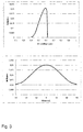
- Fig. 3 the calculated reflection for a grating with a period of 0.62 ⁇ m and a depth D GK of 0.2 ⁇ m as a function of the wavelength is shown in the upper part.
- the color impression achieved with this grid is red.
- the optimum depth D lit calculated for a wavelength ⁇ of 0.63 ⁇ m according to equation (1) is theoretically 0.303 ⁇ m, so that according to equation (2) the correction factor k is 0.66.
- the calculated reflection is given as a function of the viewing angle. As can be clearly seen, the highest reflection is achieved for a viewing angle close to 0 °, ie, when viewed almost perpendicularly. When the viewing area is changed from -30 ° to 30 °, the reflection changes by less than 20%.
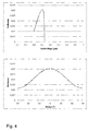
- Fig. 4 the calculated reflection for a grating with a period of 0.53 ⁇ m and a depth D GK of 0.165 ⁇ m as a function of the wavelength is shown in the upper part.
- the color impression achieved with this grid is green.
- the optimum depth D lit calculated for a wavelength ⁇ of 0.53 ⁇ m according to equation (1) is theoretically 0.25 ⁇ m, so that according to equation (2) the correction factor k is 0.66.
- the calculated reflection is given as a function of the viewing angle. As can be clearly seen, the highest reflection is achieved for a viewing angle close to 0 °, ie, when viewed almost perpendicularly.
- the reflection changes by less than 20%.
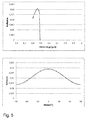
- Fig. 5 the calculated reflection for a grating with a period of 0.49 ⁇ m and a depth D GK of 0.145 ⁇ m as a function of the wavelength is shown in the upper part.
- the color impression achieved with this grid is blue.
- the optimum depth D lit calculated for a wavelength ⁇ of 0.53 ⁇ m according to equation (1) is theoretically 0.226 ⁇ m, so that according to equation (2) the correction factor k amounts to 0.64.
- the calculated reflection is given as a function of the viewing angle. As can be clearly seen, the highest reflection is achieved for a viewing angle close to 0 °, ie, when viewed almost perpendicularly. When the viewing area is changed from -30 ° to 30 °, the reflection changes by less than 20%.
- Fig. 6 to illustrate the so-called "moth eye effect" at the top of a calculated reflection spectrum for a wavelength ⁇ of 0.5 microns for a grid with the period 0.25 microns, a depth of 0.3 microns. Due to the nanostructuring of the surface through the grid, only a very small reflection is achieved.
- a calculated reflection spectrum for a grating having a period of 0.25 ⁇ m and a depth of 0.1 ⁇ m for a wavelength ⁇ of 0.5 ⁇ m is also shown. Again, an extremely low reflection is achieved.
- Fig. 7 schematically in the upper part of a glass ceramic 1 with a plurality of laterally structured regions 5, shown here in troughs 20, shown, in which case the laterally structured regions 5 are not designated, since they completely cover the region 20 of the upper surface 2 of the glass ceramic 1 ie in In this example, the areas 5 are identical to the wells 20. Also designated is the line A, along which a section was made through the glass-ceramic 1, this section in the lower part of Fig. 7 is shown.
- the troughs 20 have per se periodic and / or quasi-periodic structures 6, for example in the form of a micro and / or nanostructure, which were each realized by laser ablation.
- 20 ceramic colors may be located in the wells, each of which may cover the entire well 20 or even a portion of it, wherein the color penetration has been realized with a laser. It is also possible that in each case only a portion of the wells is provided with periodic and / or quasi-periodic structures 6. Furthermore, under the wells 20 may be a light source and / or a sensor. The glass ceramic has two surfaces, namely the top 2 and the bottom 3. The bottom 3 of the glass ceramic 1 is in Fig. 7 but shown as smooth, but can also be knobbed. Such a laterally structured region 5 formed in a trough 20 increases the user-friendliness of the cooking surface through the haptic support of the operation.
- luminous sources are located underneath the depressions, it is furthermore possible to optimize them by the appropriate structuring of the laterally structured region 5 by means of periodic and / or quasi-periodic structures 6 with regard to their focusing or defocusing of the light, and thus further the user-friendliness of the light Cooking surface to improve.
- a section along the section line designated A This in particular shows the shape of the wells 20.
- the wells 20 thus have a surface which has a curvature, ie is not flat, in which case a curvature is understood to mean a curvature having a radius of curvature of at least 1 mm or more.
- Fig. 8 is schematically in the upper part of a wok glass ceramic 1 with a laterally structured region 5 (not labeled), here formed in a trough 20, shown, in which case the laterally structured region 5 are not designated, since he designed as a trough 20 area the top 2 of the glass ceramic 1 completely covered, ie in this example the area 5 is identical to the trough 20, and in the lower area a section through the glass ceramic 1 along the top of the Fig. 8
- the depression 20 has periodic and / or quasi-periodic structures 6, for example in the form of a microstructure and / or nanostructure, which have each been realized by laser ablation.
- 20 ceramic colors may be in the trough, wherein the color penetration has been realized with a laser.
- a light source and / or a sensor can be located under the trough 20.
- the glass ceramic 1 has two surfaces, namely the top 2 and the bottom 3.
- the bottom 3 of the glass ceramic 1 is in Fig. 7 but shown as smooth, but can also be knobbed.
- the overall curved shape of the glass-ceramic becomes clear, so that Here, the glass ceramic is present in the form of a 3D molded body.
- the curved surface of the glass ceramic in the trough 20 can be seen.
- the curvature here is understood as a curvature which has a radius of curvature of at least 1 mm or more.
- Fig. 9 shows a schematic representation of drops 12 in different areas 30, 40 and 50 on the upper side 2 of a glass ceramic 1.
- the underside 3 of the glass ceramic 1 is here shown smooth, but can also be designed genoppt or otherwise structured.
- the contact angle of the drop 12 is less than 80 °, and the drop 12 spreads on the surface 32 of the region 30. It is also said that such a surface 32 is hydrophilic and good Wettability has.
- a second drop 12 is shown in the central region 40 of the glass ceramic 1. This has to the surface 42 of the area 40 on a contact angle between 80-120 °. This is called surface 42 has hydrophobic properties. This may be the case, for example, if the surface 42 for hydrophobization has been provided with a silanization layer.
- a third drop 12 is shown in the right area 50 of the glass ceramic 1. This has to the surface 52 of the region 50 of the glass ceramic 1 to a contact angle of 120 ° or more. The drop 12 thus hardly wets the surface 52. The surface 52 thus has a so-called Super hydrophobicity on.
- Such superhydrophobicity can be realized by suitable structuring of a surface, for example in the form of periodic and / or quasiperiodic structures 6 (not shown).
- Fig. 10 shows a schematic representation of periodic and / or quasi-periodic structures 6 in a laterally structured region 5 of the glass ceramic 1, which are located on the upper side 2 of the glass ceramic 1.
- the bottom 3 of the glass ceramic 1 is shown here smooth, but can also be studded.
- not all structures 6 have been designated.
- the structures 6 do not protrude beyond the original surface of the glass ceramic and are located within the amorphous surface zone of the glass ceramic. Furthermore, they are characterized by a period a and a width b of the structure.
- the terms "period of the structure”, “period of the structures” and “period structure” are used synonymously in the context of this invention, as are the terms “width of the structures", “width of the structure” and “structure width”.
- 2D lattices which have a ratio of b: a of 0.4 to 0.6 are preferred.
- the ratio of structure width b to period structure a is also called the duty cycle.
- structures are particularly suitable which have non-rectangular edges, such as pyramidal, cylindrical and / or trapezoidal structures with rounded edges.
Landscapes
- Engineering & Computer Science (AREA)
- Physics & Mathematics (AREA)
- Chemical & Material Sciences (AREA)
- Optics & Photonics (AREA)
- Mechanical Engineering (AREA)
- Materials Engineering (AREA)
- Life Sciences & Earth Sciences (AREA)
- Chemical Kinetics & Catalysis (AREA)
- General Chemical & Material Sciences (AREA)
- Geochemistry & Mineralogy (AREA)
- Organic Chemistry (AREA)
- Plasma & Fusion (AREA)
- General Physics & Mathematics (AREA)
- General Engineering & Computer Science (AREA)
- Combustion & Propulsion (AREA)
- Health & Medical Sciences (AREA)
- Toxicology (AREA)
- Ceramic Engineering (AREA)
- Crystallography & Structural Chemistry (AREA)
- Dispersion Chemistry (AREA)
- Spectroscopy & Molecular Physics (AREA)
- Surface Treatment Of Glass (AREA)
Applications Claiming Priority (1)
| Application Number | Priority Date | Filing Date | Title |
|---|---|---|---|
| DE102015101332.0A DE102015101332A1 (de) | 2015-01-29 | 2015-01-29 | Glaskeramik mit besonders ausgestalteter Oberfläche sowie Verfahren zu deren Herstellung |
Publications (1)
| Publication Number | Publication Date |
|---|---|
| EP3050855A1 true EP3050855A1 (fr) | 2016-08-03 |
Family
ID=55236195
Family Applications (1)
| Application Number | Title | Priority Date | Filing Date |
|---|---|---|---|
| EP16151955.8A Withdrawn EP3050855A1 (fr) | 2015-01-29 | 2016-01-19 | Vitroceramique ayant une surface speciale et son procede de fabrication |
Country Status (3)
| Country | Link |
|---|---|
| US (1) | US20160223206A1 (fr) |
| EP (1) | EP3050855A1 (fr) |
| DE (1) | DE102015101332A1 (fr) |
Families Citing this family (4)
| Publication number | Priority date | Publication date | Assignee | Title |
|---|---|---|---|---|
| EP3718981A3 (fr) * | 2019-04-05 | 2020-12-16 | Schott AG | Mécanismes de retenue de déversements pour tables de cuisson et autres substrats |
| DE102019206380B4 (de) * | 2019-05-03 | 2024-11-07 | Audi Ag | Haushaltsgerät mit einem Kochfeld |
| DE102019116456A1 (de) * | 2019-06-18 | 2020-12-24 | Gerresheimer Regensburg Gmbh | Verfahren und Vorrichtung zur Herstellung einer Struktur in der Oberfläche eines rotationssymmetrischen Glaskörpers |
| JP7708770B2 (ja) * | 2020-01-17 | 2025-07-15 | コーニング インコーポレイテッド | 基板面を処理する方法、そのための装置、及び処理されたガラス物品 |
Citations (10)
| Publication number | Priority date | Publication date | Assignee | Title |
|---|---|---|---|---|
| DE19918811A1 (de) | 1999-04-26 | 2000-11-02 | Fraunhofer Ges Forschung | Vorgespanntes, mit einer wischfesten, porösen SiO¶2¶-Antireflex-Schicht versehenes Sicherheitsglas u. Verfahren z. d. Herstellung |
| WO2001074739A1 (fr) | 2000-04-01 | 2001-10-11 | Dmc?2¿ Degussa Metals Catalyts Cerdec Ag | Substrats en verre, en ceramique et en metal pourvus d'une surface auto-nettoyante, leur procede de production et leur utilisation |
| EP1876394A2 (fr) | 2006-07-03 | 2008-01-09 | BSH Bosch und Siemens Hausgeräte GmbH | Bande d'affichage avec une structure haptique en relief |
| WO2009128893A1 (fr) * | 2008-04-18 | 2009-10-22 | Corning Incorporated | Procédés et systèmes de formation de microstructures dans des substrats de verre |
| DE202009000139U1 (de) | 2009-01-05 | 2010-05-12 | Irlbacher Blickpunkt Glas Gmbh | Berührungsempfindlicher Gleitschalter |
| WO2011106196A1 (fr) * | 2010-02-24 | 2011-09-01 | Corning Incorporated | Substrats de verre oléophobes |
| DE102005040588B4 (de) | 2004-08-20 | 2011-11-10 | Schott Ag | Verwendung eines blei- und cadmiumfreien Glases sowie Verfahren zum Glasieren, Emaillieren und Dekorieren von Lithium-Aluminosilikat-Glaskeramiken |
| WO2012062467A1 (fr) | 2010-11-10 | 2012-05-18 | Schott Ag | Produit de verre ou de vitrocéramique ayant une couche de faible énergie stable aux températures élevées |
| DE102013103776A1 (de) * | 2013-04-15 | 2014-06-18 | Schott Ag | Glaskeramik-Kochfläche mit lokal erhöhter Transmission und Verfahren zur Herstellung einer solchen Glaskeramik-Kochfläche |
| EP2805829A1 (fr) * | 2013-04-15 | 2014-11-26 | Schott AG | Table de cuisson en vitrocéramique avec transmission localement accrue et procédé de fabrication d'une telle table de cuisson en vitrocéramique |
Family Cites Families (5)
| Publication number | Priority date | Publication date | Assignee | Title |
|---|---|---|---|---|
| JPH04211202A (ja) * | 1990-03-19 | 1992-08-03 | Canon Inc | 反射型回折格子および該回折格子を用いた装置 |
| DE4338969C2 (de) * | 1993-06-18 | 1996-09-19 | Schott Glaswerke | Verfahren zur Herstellung anorganischer diffraktiver Elemente und Verwendung derselben |
| DE19803787A1 (de) * | 1998-01-30 | 1999-08-05 | Creavis Tech & Innovation Gmbh | Strukturierte Oberflächen mit hydrophoben Eigenschaften |
| DE10238608A1 (de) * | 2002-08-16 | 2004-03-04 | Schott Glas | Bauteil aus einer Lithiumaluminosilikat-Glaskeramik |
| DE102004020363A1 (de) * | 2004-04-23 | 2005-11-17 | Schott Ag | Verfahren zur Herstellung eines Masters, Master und Verfahren zur Herstellung von optischen Elementen sowie optischen Element |
-
2015
- 2015-01-29 DE DE102015101332.0A patent/DE102015101332A1/de not_active Withdrawn
-
2016
- 2016-01-19 EP EP16151955.8A patent/EP3050855A1/fr not_active Withdrawn
- 2016-01-29 US US15/009,912 patent/US20160223206A1/en not_active Abandoned
Patent Citations (10)
| Publication number | Priority date | Publication date | Assignee | Title |
|---|---|---|---|---|
| DE19918811A1 (de) | 1999-04-26 | 2000-11-02 | Fraunhofer Ges Forschung | Vorgespanntes, mit einer wischfesten, porösen SiO¶2¶-Antireflex-Schicht versehenes Sicherheitsglas u. Verfahren z. d. Herstellung |
| WO2001074739A1 (fr) | 2000-04-01 | 2001-10-11 | Dmc?2¿ Degussa Metals Catalyts Cerdec Ag | Substrats en verre, en ceramique et en metal pourvus d'une surface auto-nettoyante, leur procede de production et leur utilisation |
| DE102005040588B4 (de) | 2004-08-20 | 2011-11-10 | Schott Ag | Verwendung eines blei- und cadmiumfreien Glases sowie Verfahren zum Glasieren, Emaillieren und Dekorieren von Lithium-Aluminosilikat-Glaskeramiken |
| EP1876394A2 (fr) | 2006-07-03 | 2008-01-09 | BSH Bosch und Siemens Hausgeräte GmbH | Bande d'affichage avec une structure haptique en relief |
| WO2009128893A1 (fr) * | 2008-04-18 | 2009-10-22 | Corning Incorporated | Procédés et systèmes de formation de microstructures dans des substrats de verre |
| DE202009000139U1 (de) | 2009-01-05 | 2010-05-12 | Irlbacher Blickpunkt Glas Gmbh | Berührungsempfindlicher Gleitschalter |
| WO2011106196A1 (fr) * | 2010-02-24 | 2011-09-01 | Corning Incorporated | Substrats de verre oléophobes |
| WO2012062467A1 (fr) | 2010-11-10 | 2012-05-18 | Schott Ag | Produit de verre ou de vitrocéramique ayant une couche de faible énergie stable aux températures élevées |
| DE102013103776A1 (de) * | 2013-04-15 | 2014-06-18 | Schott Ag | Glaskeramik-Kochfläche mit lokal erhöhter Transmission und Verfahren zur Herstellung einer solchen Glaskeramik-Kochfläche |
| EP2805829A1 (fr) * | 2013-04-15 | 2014-11-26 | Schott AG | Table de cuisson en vitrocéramique avec transmission localement accrue et procédé de fabrication d'une telle table de cuisson en vitrocéramique |
Also Published As
| Publication number | Publication date |
|---|---|
| DE102015101332A1 (de) | 2016-08-04 |
| US20160223206A1 (en) | 2016-08-04 |
Similar Documents
| Publication | Publication Date | Title |
|---|---|---|
| EP3031785B1 (fr) | Procede de fabrication d'un element en vitroceramique faisant appel a un revetement structure | |
| DE69705827T2 (de) | Laserherstellungsverfahren für glassubstrate, und damit hergestellte beugunggitter | |
| EP3210948B1 (fr) | Article en vitroceramique ou en verre revetu | |
| EP4367558B1 (fr) | Dispositif et procédé de structuration par interférence laser de substrats afin de les doter de structures ponctuelles périodiques leur conférant des propriétés antireflet | |
| DE69707118T2 (de) | Verfahren zur herstellung eines glasartikels | |
| EP1871566B1 (fr) | Procede de polissage fin/structuration de matieres dielectriques thermosensibles au moyen d'un rayonnement laser | |
| DE102008056136A1 (de) | Lasermarkierverfahren, Lasermarkiervorrichtung und Optikelement | |
| DE102014118497B4 (de) | Verfahren zur Herstellung eines Glaskeramikelements mit strukturierter Beschichtung, plattenförmig ausgebildetes Glaskeramikelement und Glaskeramik-Kochfeld | |
| DE102004020363A1 (de) | Verfahren zur Herstellung eines Masters, Master und Verfahren zur Herstellung von optischen Elementen sowie optischen Element | |
| WO2015044168A1 (fr) | Coloration en volume induite par laser de verre et de vitrocéramiques | |
| EP3050855A1 (fr) | Vitroceramique ayant une surface speciale et son procede de fabrication | |
| WO2017060252A1 (fr) | Pièce diélectrique présentant une zone de résistance ajustée de manière prédéfinie, procédé d'utilisation de ladite pièce et son utilisation | |
| EP1728770B1 (fr) | Procédé pour le marquage des surfaces d'objets | |
| DE102020126856A1 (de) | Glaselement mit strukturierter Wandung und Verfahren zu dessen Herstellung | |
| EP4126436B1 (fr) | Procédé pour produire une structure de déviation de lumière, utilisation d'un substrat avec une telle structure de déviation de lumière, et unité de déviation de lumière équipée d'une telle structure de déviation de lumière | |
| DE102020107944B4 (de) | Verfahren zur Herstellung eines kontinuierlichen diffraktiven optischen Elementes und kontinuierliches diffraktives optisches Element | |
| DE10118876A1 (de) | Verfahren zur Herstellung farbiger Strukturen eines Glases | |
| EP3959181A1 (fr) | Procédé de production d'une vitre dotée d'un revêtement structuré | |
| WO2020143945A1 (fr) | Procédé de fabrication d'une vitre revêtue présentant une zone transparente | |
| DE10237732A1 (de) | Laserstrahlmarkierungsverfahren sowie Markierungsvorrichtung zur Laserstrahlmarkierung eines Zielsubstrats | |
| WO2016058579A1 (fr) | Procédé de fabrication d'un élément de façade en verre de protection contre la lumiere et élément de facade de protection contre la lumiere | |
| DE102020106768A1 (de) | Verfahren zur umformenden Bearbeitung eines Trägersubstrates für ein optisches Funktionsbauteil | |
| EP1714172B1 (fr) | Procede pour produire un composant optique par usinage laser provoquant une structuration de surface | |
| DE102005055174B3 (de) | Verfahren zum Abtrag von lichtdurchlässigen Materialien mit Laserstrahlung und Vorrichtung hierfür | |
| EP2857138B1 (fr) | Procédé de fabrication d'une microstructure voûtée |
Legal Events
| Date | Code | Title | Description |
|---|---|---|---|
| PUAI | Public reference made under article 153(3) epc to a published international application that has entered the european phase |
Free format text: ORIGINAL CODE: 0009012 |
|
| 17P | Request for examination filed |
Effective date: 20160119 |
|
| AK | Designated contracting states |
Kind code of ref document: A1 Designated state(s): AL AT BE BG CH CY CZ DE DK EE ES FI FR GB GR HR HU IE IS IT LI LT LU LV MC MK MT NL NO PL PT RO RS SE SI SK SM TR |
|
| AX | Request for extension of the european patent |
Extension state: BA ME |
|
| RBV | Designated contracting states (corrected) |
Designated state(s): AL AT BE BG CH CY CZ DE DK EE ES FI FR GB GR HR HU IE IS IT LI LT LU LV MC MK MT NL NO PL PT RO RS SE SI SK SM TR |
|
| STAA | Information on the status of an ep patent application or granted ep patent |
Free format text: STATUS: THE APPLICATION IS DEEMED TO BE WITHDRAWN |
|
| 18D | Application deemed to be withdrawn |
Effective date: 20180801 |