EP3050996A1 - Implantat und herstellungsverfahren dafür - Google Patents
Implantat und herstellungsverfahren dafür Download PDFInfo
- Publication number
- EP3050996A1 EP3050996A1 EP13894102.6A EP13894102A EP3050996A1 EP 3050996 A1 EP3050996 A1 EP 3050996A1 EP 13894102 A EP13894102 A EP 13894102A EP 3050996 A1 EP3050996 A1 EP 3050996A1
- Authority
- EP
- European Patent Office
- Prior art keywords
- magnesium
- implant
- alloy
- compressing
- alloy material
- Prior art date
- Legal status (The legal status is an assumption and is not a legal conclusion. Google has not performed a legal analysis and makes no representation as to the accuracy of the status listed.)
- Withdrawn
Links
Images





Classifications
-
- C—CHEMISTRY; METALLURGY
- C22—METALLURGY; FERROUS OR NON-FERROUS ALLOYS; TREATMENT OF ALLOYS OR NON-FERROUS METALS
- C22C—ALLOYS
- C22C23/00—Alloys based on magnesium
- C22C23/06—Alloys based on magnesium with a rare earth metal as the next major constituent
-
- A—HUMAN NECESSITIES
- A61—MEDICAL OR VETERINARY SCIENCE; HYGIENE
- A61F—FILTERS IMPLANTABLE INTO BLOOD VESSELS; PROSTHESES; DEVICES PROVIDING PATENCY TO, OR PREVENTING COLLAPSING OF, TUBULAR STRUCTURES OF THE BODY, e.g. STENTS; ORTHOPAEDIC, NURSING OR CONTRACEPTIVE DEVICES; FOMENTATION; TREATMENT OR PROTECTION OF EYES OR EARS; BANDAGES, DRESSINGS OR ABSORBENT PADS; FIRST-AID KITS
- A61F2/00—Filters implantable into blood vessels; Prostheses, i.e. artificial substitutes or replacements for parts of the body; Appliances for connecting them with the body; Devices providing patency to, or preventing collapsing of, tubular structures of the body, e.g. stents
- A61F2/02—Prostheses implantable into the body
- A61F2/28—Bones
-
- A—HUMAN NECESSITIES
- A61—MEDICAL OR VETERINARY SCIENCE; HYGIENE
- A61L—METHODS OR APPARATUS FOR STERILISING MATERIALS OR OBJECTS IN GENERAL; DISINFECTION, STERILISATION OR DEODORISATION OF AIR; CHEMICAL ASPECTS OF BANDAGES, DRESSINGS, ABSORBENT PADS OR SURGICAL ARTICLES; MATERIALS FOR BANDAGES, DRESSINGS, ABSORBENT PADS OR SURGICAL ARTICLES
- A61L27/00—Materials for grafts or prostheses or for coating grafts or prostheses
-
- A—HUMAN NECESSITIES
- A61—MEDICAL OR VETERINARY SCIENCE; HYGIENE
- A61L—METHODS OR APPARATUS FOR STERILISING MATERIALS OR OBJECTS IN GENERAL; DISINFECTION, STERILISATION OR DEODORISATION OF AIR; CHEMICAL ASPECTS OF BANDAGES, DRESSINGS, ABSORBENT PADS OR SURGICAL ARTICLES; MATERIALS FOR BANDAGES, DRESSINGS, ABSORBENT PADS OR SURGICAL ARTICLES
- A61L31/00—Materials for other surgical articles, e.g. stents, stent-grafts, shunts, surgical drapes, guide wires, materials for adhesion prevention, occluding devices, surgical gloves, tissue fixation devices
- A61L31/02—Inorganic materials
- A61L31/022—Metals or alloys
-
- A—HUMAN NECESSITIES
- A61—MEDICAL OR VETERINARY SCIENCE; HYGIENE
- A61L—METHODS OR APPARATUS FOR STERILISING MATERIALS OR OBJECTS IN GENERAL; DISINFECTION, STERILISATION OR DEODORISATION OF AIR; CHEMICAL ASPECTS OF BANDAGES, DRESSINGS, ABSORBENT PADS OR SURGICAL ARTICLES; MATERIALS FOR BANDAGES, DRESSINGS, ABSORBENT PADS OR SURGICAL ARTICLES
- A61L31/00—Materials for other surgical articles, e.g. stents, stent-grafts, shunts, surgical drapes, guide wires, materials for adhesion prevention, occluding devices, surgical gloves, tissue fixation devices
- A61L31/14—Materials characterised by their function or physical properties, e.g. injectable or lubricating compositions, shape-memory materials, surface modified materials
- A61L31/148—Materials at least partially resorbable by the body
-
- B—PERFORMING OPERATIONS; TRANSPORTING
- B21—MECHANICAL METAL-WORKING WITHOUT ESSENTIALLY REMOVING MATERIAL; PUNCHING METAL
- B21C—MANUFACTURE OF METAL SHEETS, WIRE, RODS, TUBES, PROFILES OR LIKE SEMI-MANUFACTURED PRODUCTS OTHERWISE THAN BY ROLLING; AUXILIARY OPERATIONS USED IN CONNECTION WITH METAL-WORKING WITHOUT ESSENTIALLY REMOVING MATERIAL
- B21C23/00—Extruding metal; Impact extrusion
- B21C23/001—Extruding metal; Impact extrusion to improve the material properties, e.g. lateral extrusion
-
- B—PERFORMING OPERATIONS; TRANSPORTING
- B21—MECHANICAL METAL-WORKING WITHOUT ESSENTIALLY REMOVING MATERIAL; PUNCHING METAL
- B21J—FORGING; HAMMERING; PRESSING METAL; RIVETING; FORGE FURNACES
- B21J5/00—Methods for forging, hammering, or pressing; Special equipment or accessories therefor
-
- B—PERFORMING OPERATIONS; TRANSPORTING
- B21—MECHANICAL METAL-WORKING WITHOUT ESSENTIALLY REMOVING MATERIAL; PUNCHING METAL
- B21K—MAKING FORGED OR PRESSED METAL PRODUCTS, e.g. HORSE-SHOES, RIVETS, BOLTS OR WHEELS
- B21K1/00—Making machine elements
- B21K1/76—Making machine elements elements not mentioned in one of the preceding groups
-
- B—PERFORMING OPERATIONS; TRANSPORTING
- B23—MACHINE TOOLS; METAL-WORKING NOT OTHERWISE PROVIDED FOR
- B23P—METAL-WORKING NOT OTHERWISE PROVIDED FOR; COMBINED OPERATIONS; UNIVERSAL MACHINE TOOLS
- B23P15/00—Making specific metal objects by operations not covered by a single other subclass or a group in this subclass
-
- C—CHEMISTRY; METALLURGY
- C22—METALLURGY; FERROUS OR NON-FERROUS ALLOYS; TREATMENT OF ALLOYS OR NON-FERROUS METALS
- C22F—CHANGING THE PHYSICAL STRUCTURE OF NON-FERROUS METALS AND NON-FERROUS ALLOYS
- C22F1/00—Changing the physical structure of non-ferrous metals or alloys by heat treatment or by hot or cold working
- C22F1/06—Changing the physical structure of non-ferrous metals or alloys by heat treatment or by hot or cold working of magnesium or alloys based thereon
-
- A—HUMAN NECESSITIES
- A61—MEDICAL OR VETERINARY SCIENCE; HYGIENE
- A61F—FILTERS IMPLANTABLE INTO BLOOD VESSELS; PROSTHESES; DEVICES PROVIDING PATENCY TO, OR PREVENTING COLLAPSING OF, TUBULAR STRUCTURES OF THE BODY, e.g. STENTS; ORTHOPAEDIC, NURSING OR CONTRACEPTIVE DEVICES; FOMENTATION; TREATMENT OR PROTECTION OF EYES OR EARS; BANDAGES, DRESSINGS OR ABSORBENT PADS; FIRST-AID KITS
- A61F2210/00—Particular material properties of prostheses classified in groups A61F2/00 - A61F2/26 or A61F2/82 or A61F9/00 or A61F11/00 or subgroups thereof
- A61F2210/0004—Particular material properties of prostheses classified in groups A61F2/00 - A61F2/26 or A61F2/82 or A61F9/00 or A61F11/00 or subgroups thereof bioabsorbable
-
- A—HUMAN NECESSITIES
- A61—MEDICAL OR VETERINARY SCIENCE; HYGIENE
- A61F—FILTERS IMPLANTABLE INTO BLOOD VESSELS; PROSTHESES; DEVICES PROVIDING PATENCY TO, OR PREVENTING COLLAPSING OF, TUBULAR STRUCTURES OF THE BODY, e.g. STENTS; ORTHOPAEDIC, NURSING OR CONTRACEPTIVE DEVICES; FOMENTATION; TREATMENT OR PROTECTION OF EYES OR EARS; BANDAGES, DRESSINGS OR ABSORBENT PADS; FIRST-AID KITS
- A61F2240/00—Manufacturing or designing of prostheses classified in groups A61F2/00 - A61F2/26 or A61F2/82 or A61F9/00 or A61F11/00 or subgroups thereof
- A61F2240/001—Designing or manufacturing processes
-
- A—HUMAN NECESSITIES
- A61—MEDICAL OR VETERINARY SCIENCE; HYGIENE
- A61F—FILTERS IMPLANTABLE INTO BLOOD VESSELS; PROSTHESES; DEVICES PROVIDING PATENCY TO, OR PREVENTING COLLAPSING OF, TUBULAR STRUCTURES OF THE BODY, e.g. STENTS; ORTHOPAEDIC, NURSING OR CONTRACEPTIVE DEVICES; FOMENTATION; TREATMENT OR PROTECTION OF EYES OR EARS; BANDAGES, DRESSINGS OR ABSORBENT PADS; FIRST-AID KITS
- A61F2310/00—Prostheses classified in A61F2/28 or A61F2/30 - A61F2/44 being constructed from or coated with a particular material
- A61F2310/00005—The prosthesis being constructed from a particular material
- A61F2310/00011—Metals or alloys
- A61F2310/00035—Other metals or alloys
- A61F2310/00041—Magnesium or Mg-based alloys
Definitions
- the present invention relates to an implant and a method of manufacturing the same, and relates, in particular, to a magnesium-alloy implant.
- Magnesium and magnesium alloys have lower weights and higher strengths as compared with other metals, and they are beginning to be put to practical use in portable electronic equipment, automobile parts, and so forth.
- magnesium is characterized by biodegradability, there have been advances in research for applications in absorbable stents and absorbable bone-joining materials (for example, see Patent Literature 1).
- the present invention has been conceived in light of the above-described circumstances, and an object thereof is to provide an implant in which the occurrence of a structural defect is suppressed and that has a low degradation rate and a method of manufacturing the same.
- the present invention provides the following solutions.
- a first aspect of the present invention is an implant manufacturing method including a molding step of molding a molded item by treating a raw-material piece constituted of a biodegradable metal material with plastic processing; and a grain-size adjusting step of increasing a metal grain size by applying a heat treatment to the molded item molded in the molding step.
- the metal grain sizes constituting the biodegradable metal material become finer.
- the metal grain sizes are increased by subsequently applying the heat treatment to the molded item in the grain-size adjusting step, and thus, it is possible to decrease the degradation rate when the implant is embedded in a living organism as an implant. By doing so, it is possible to manufacture an implant that is degraded after functioning for a long time as a structure after being implanted.
- the molding step may include an extruding step of obtaining a plastically-deformed molded magnesium-alloy material by extruding a magnesium alloy; a cutting step of cutting the molded magnesium-alloy material obtained in the extruding step at an angle of 70° to 110° with respect to the extrusion direction; and a compressing step of exerting a compressing force on a lump of magnesium-alloy material obtained in the cutting step in a direction orthogonal to the extrusion direction.
- the plastically-deformed molded magnesium-alloy material in which the c-axes of the magnesium metal crystals are oriented in substantially 90° directions with respect to the extruding direction is obtained by extruding the magnesium alloy in the extruding step.
- the lump of magnesium-alloy material is obtained in the cutting step by cutting the molded magnesium-alloy material at an angle from 70° to 110° with respect to extrusion direction.
- the plastically-processed item is manufactured in the compressing step by exerting the compressing force on the lump of magnesium-alloy material in the direction orthogonal to the extrusion direction.
- the compressing force is exerted mainly in the c-axis direction
- the compressing force acts in the direction orthogonal to the slip planes of the metal crystals of the magnesium alloy.
- the processability is decreased as compared with the case in which the compressing force is exerted in the direction orthogonal to the c-axis, it is possible to manufacture a plastically-processed item having a smaller number of structural defects. In other words, it is possible to manufacture a high-strength plastically-processed item.
- the above-described first aspect may include, before the compressing step or in the compressing step, a heating step of heating the lump of magnesium-alloy material.
- the lump of magnesium-alloy material in the heating step, may be heated at a temperature that is greater than 300 °C, or, more preferably, that is equal to or greater 350 °C, and that is equal to or less than the melting point of the magnesium alloy.
- the lump of magnesium-alloy material in the compressing step, may be compressed at a reduction ratio equal to or greater than 45 %.
- the compressing force may be exerted by using a metal mold in a state in which a lubricant is applied between the lump of magnesium-alloy material and the metal mold.
- the above-described first aspect may include a shearing step of cutting out a product from the compressed magnesium-alloy material after the compressing step, wherein the shearing step is performed at a reduction rate of 1.5 mm/s or less.
- a plastically-processed product is manufactured by subjecting the magnesium-alloy material compressed in the compressing step to the shearing step.
- the shearing step involves, for example, punching process by means of a press apparatus.
- a relatively-smooth sheared portion (sheared surface) and a fractured portion (fractured surface) that is instantaneously separated to have a rough surface are created at the cut surface.
- the shearing step at a reduction rate equal to or less than 1.5 mm/s, the fractured portion at the cut surface is suppressed to 50 % or less.
- the above-described first aspect may include a washing step of washing a surface of the molded item molded in the molding step; and a checking step of checking the impurity concentration at the surface of the molded item that has been washed in the washing step, wherein, in the grain-size adjusting step, the heat treatment is applied to the molded item in the case in which the impurity concentration checked in the checking step is equal to or less than a predetermined value.
- the metal component remains, as an impurity, on the surface of the molded item that has come into contact with the metal mold when treated with plastic processing.
- the residual impurity is washed in the washing step, and the concentration thereof is subsequently checked in the checking step.
- the grain-size adjusting step is performed in the case in which the impurity concentration on the surface of the molded item is equal to or less than the predetermined value, it is possible to manufacture an implant having a more stable degradation rate by preventing the biodegradable metal material and the impurity metal material from reacting with each other during the heat treatment.
- the washing step may involve a treatment for peeling the surface of the molded item.
- the washing step may involve a treatment for dissolving the surface of the molded item by using an acid.
- the impurity metal material attached to the surface of the molded item is dissolved by the acid and is removed together with the surface portion of the molded item.
- the washing step may include a treatment for dissolving the surface of the molded item by using an acid and a subsequent treatment for immersing the molded item in an alkaline solution.
- the impurity metal material attached to the surface of the molded item is dissolved by the acid and removed together with the surface portion of the molded item. Then, the dissolution reaction by the acid can be stopped by means of immersion in the alkaline solution.
- the grain-size adjusting step may involve a solutionizing treatment.
- an aging precipitation treatment may be performed after the solutionizing treatment.
- a second aspect of the present invention is a magnesium-alloy implant in which c-axes of metal crystals are oriented in a main load direction.
- an average value of deviation angles of normals at (0001) planes of metal crystals with respect to a thickness direction may be equal to or less than 25°.
- an average value of deviation angles of normals at (0001) planes of metal crystals with respect to a direction parallel to a surface may be equal to or greater than 80°, and a width of a cumulative distribution of the deviation angles that are from 16 to 84 % of a maximum value of the deviation angles may be equal to or less than 50°.
- the above-described second aspect may be manufactured by punching processing.
- a fraction of sheared portions at a cut surface along a thickness direction formed by punching processing be equal to or greater than 50 % relative to the thickness.
- an Fe-ion concentration may be equal to or less than 0.02 %
- a Cu-ion concentration may be equal to or less than 0.15 %
- a nickel concentration may be equal to or less than 0.01 %.
- the present invention affords an advantage in that it is possible to manufacture an implant having a low degradation rate by preventing the occurrence of a structural defect.
- An implant that is manufactured by using the manufacturing method according to this embodiment is, for example, an implant to be used for joining bones, and is constituted of a biodegradable metal material, for example, a magnesium-alloy material (for example, WE43).
- a biodegradable metal material for example, a magnesium-alloy material (for example, WE43).
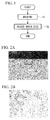
- the implant manufacturing method includes a molding step S1 of molding a molded item by treating a raw-material piece constituted of a biodegradable metal material with hot plastic processing, such as stamping, and a grain-size adjusting step S2 of applying heat treatment, which increases the grain size, to the molded item molded in the molding step S1.
- the molding step S1 is a step of stamping for, for example, 1 minute at 300 °C and 100 MPa.
- the temperature, pressure, and processing time for stamping are mere examples, and it is permissible to employ other conditions.
- the grain-size adjusting step S2 is a step of air cooling after applying heat treatment (solutionizing treatment) for, for example, eight hours at 525 °C.
- heat treatment solutionizing treatment
- the temperature and treatment time for the heat treatment are mere examples, and it is permissible to employ other conditions.
- a molded item having a desired shape is manufactured from the raw-material piece.
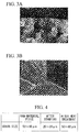
- the grain sizes of the biodegradable metal material become finer, as shown in Figs. 2A and 2B.
- Fig. 2B is an enlarged photomicrograph of the portion surrounded by a rectangle in Fig. 2A .
- Fig. 3B is an enlarged photomicrograph of the portion surrounded by a rectangle in Fig. 3A .
- Fig. 4 shows the grain sizes of the biodegradable metal material in the raw-material piece, after stamping, and after the heat treatment, respectively.
- the grain sizes of the biodegradable metal material that have been made finer by stamping in the molding step S1 are increased by the heat treatment in the grain-size adjusting step S2.
- the number of the grain boundaries at the surface of the molded item are decreased, and thus, it is possible to decrease the degradation rate.
- the implant implanted to serve as a structural material for bonding bones can maintain a sufficient strength to serve as the structural material for a long time after being implanted, thus making it possible to assist bone joining by bone formation. Then, after bone joining is completed, the implant is degraded and eliminated over time, thus preventing a foreign object from remaining in the body interior.
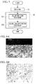
- heat treatment aging precipitation treatment (step S22)
- step S21 the solutionizing treatment
- step S21 the solutionizing treatment
- Fig. 6B is an enlarged photomicrograph of the portion surrounded by a rectangle in Fig. 6A .
- the manufacturing method includes, between the molding step S1 and the grain-size adjusting step S2, a washing step S3 of washing the molded item that has been molded, a checking step S4 of checking the impurity concentration at the surface of the molded item, and a judging step S5 of judging whether or not the impurity concentration checked in the checking step S4 is below a predetermined threshold.
- the washing step S3 is a step of degreasing the molded item, immersing the molded item in an alkaline solution after immersion in an acidic solution, and subsequently drying the molded item.
- the checking step S4 is a step of measuring the concentration of Fe ions that have leached out into the acidic solution.
- the judging step S5 it is judged whether or not the Fe-ion concentration measured in the checking step S4 is equal to or less than the predetermined threshold. Then, in the judging step S5, if the Fe-ion concentration is equal to or less than the threshold, the process advances to the grain-size adjusting step S2, and, if the Fe-ion concentration exceeds the threshold, steps from the washing step S3 are repeated again.
- the iron component constituting the metal mold becomes attached to the surface of the molded item.
- the iron component attached to the surface of the molded item is dissolved by acid by immersing the molded item in the acidic solution in the washing step S3, thus making the iron component leach out into the acidic solution in the form of Fe ions.
- the amount of the iron component that becomes attached to the molded item from the metal mold during stamping may be experimentally determined, and the predetermined threshold may be set based on the result thereof.
- the concentration may be measured after immersion in the acidic solution for a predetermined amount of time; alternatively, Fe ions in the acidic solution may be measured over time to determine the rate of change of the concentration thereof, and the Fe-ion concentration at the point in time when the change in the concentration fell below a predetermined threshold may be measured.
- the Fe-ion concentration may be measured by directly analyzing the surface composition of the implant by using an X-ray fluorescence device.
- implants for joining bones have been described as examples, in the individual embodiments described above, alternatively, the present invention may be applied to manufacturing of other arbitrary implants.
- magnesium alloy has been described as an example of a biodegradable metal material, the present invention may be applied to other arbitrary biodegradable materials.
- iron component has been described as an example of an impurity metal material that becomes attached to the surface of the molded item, alternatively or in addition thereto, a copper component or a nickel component may be removed by washing.
- an impurity metal material is removed by immersing the molded item in the acidic solution in the washing step S3
- the impurity metal material may be removed by peeling it off from the surface of the molded item by means of cutting or the like.
- the Fe-ion concentration remaining on the implant surface be 0.02 % or less, that the Cu-ion concentration be 0.15 % or less, and that the nickel concentration be 0.01 % or less.
- the implant manufacturing method according to this embodiment differs from that of the first embodiment in terms of the molding step S1. Therefore, in this embodiment, the molding step S1 will mainly be described, and descriptions of other steps S2, S21, and S22 that are the same as those of the first embodiment will be omitted.
- the implant manufacturing method of this embodiment may additionally be provided with the washing step S3, the checking step S4, and the judging step S5 described in the second embodiment.
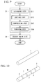
- the molding step S1 of the implant manufacturing method includes an extruding step S11 of obtaining a plastically-deformed magnesium-alloy material by extruding a magnesium-alloy material (raw-material piece), a cutting step S12 of cutting the extruded magnesium-alloy material, and a compressing step S13 of exerting a compressing force on the cut lump of magnesium-alloy material, and a punching step S14 of punching out a product from the magnesium-alloy material compressed in the compressing step.
- the extruding step S11 is a step of plastically deforming the magnesium-alloy material into a rod-shaped extruded material 1 having a predetermined lateral cross-sectional shape by using a die. Depending on the extruding conditions, orientations of metal crystals are changed so that (0001) planes of the metal crystals become oriented substantially parallel to the extrusion direction.
- the cutting step S12 is a step of obtaining lumps of magnesium-alloy material 2 that are divided in the longitudinal direction by cutting the extruded material 1 manufactured in the extruding step S11 at 70° to 110°, that is, in a direction substantially orthogonal to the longitudinal direction thereof.
- the lumps of magnesium-alloy material 2 be obtained by measuring the orientations of the (0001) planes of the extruded material 1 by means of pole figure measurement or the like and by cutting at an angle orthogonal to a surface in which the (0001) planes are mostly oriented.
- the compressing step S13 is a step of rolling the lump of magnesium-alloy material 2 into a plate by exerting a compressing force F from a reduction metal mold onto the lump of magnesium-alloy material 2 obtained in the cutting step S12 in the direction orthogonal to the extrusion direction in the extruding step S11.
- the compressing force F is exerted substantially parallel to c-axes, which are orthogonal to the (0001) planes, of metal crystals of the magnesium alloy constituting the lump of magnesium-alloy material 2.
- the compressing force F is exerted in the state in which the lump of magnesium-alloy material 2 is heated.
- the heating temperature be equal to or greater than 100 °C, which is a temperature at which non-basal slip occurs; in particular, when using WE43, which is a medical magnesium-alloy material, it is preferable that the temperature be greater than 300 °C, and it is more preferable that the temperature be equal to or greater than 350 °C.
- the compressing step S13 is performed by applying a lubricant between the metal mold and the lump of magnesium-alloy material 2.
- a lubricant between the metal mold and the lump of magnesium-alloy material 2.
- a solid lubricant, a fluid lubricant, or the like can be employed as the lubricant.
- the compressing step S13 is performed by repeating, multiple times, the step of applying the lubricant and the step of reducing the lump of magnesium-alloy material 2 by using the metal mold.
- the compressing step S13 is configured so as to compress the lump of magnesium-alloy material 2 by a reduction ratio of 45 % or greater.
- Reduction ratio thickness before compression ⁇ thickness after compression / thickness before compression ⁇ 100 %
- the punching step S14 is a step of punching out the plate-like magnesium-alloy material obtained in the compressing step S13 by using a punch die. In this punching step S14, it is preferable that the rate at which the magnesium-alloy material is reduced by using the metal mold be suppressed to 1.5 mm/s or less.
- the rod-shaped extruded material 1 is obtained by extruding the magnesium-alloy raw material in the extruding step S11.
- the orientations of metal crystals of the magnesium-alloy material are changed so that the (0001) planes of the metal crystals are oriented substantially parallel to the extrusion direction.
- the extruded material 1 obtained in this way is subjected to the cutting step S12.
- a plurality of lumps of magnesium-alloy material 2 are obtained by cutting the extruded material 1 at cut surfaces orthogonal to the extrusion direction. Specifically, the cut surfaces are arranged in the direction orthogonal to the (0001) planes of the metal crystals.
- the individual lumps of magnesium-alloy material 2 are subjected to the compressing step S13.
- the compressing force F is exerted on the lumps of magnesium-alloy material 2 in the direction orthogonal to the extrusion direction.
- the compressing force F is exerted in a direction substantially parallel to the c-axes of the metal crystals that are oriented in substantially one direction at positions in the lumps of magnesium-alloy material 2 where the diameters thereof makes the degree of processing greatest.
- This direction of the compressing force F in the compressing step S13 is the direction orthogonal to slip planes of the metal crystals, and, although the ease of plastic processing is decreased as compared with a case in which the compressing force F is exerted parallel to the slip planes, there is an advantage in that structural defects of the metal crystals are less likely to occur. In other words, there is an advantage in that, because the occurrence of structural defects in the compressed magnesium-alloy material is suppressed, it is possible to enhance the mechanical strength.
- the compressing force F is exerted in the state in which the lubricant is applied between the metal mold and the lump of magnesium-alloy material 2.
- the compressing force F is dispersed over the entire contact surface between the lump of magnesium-alloy material 2 and the metal mold by the action of the lubricant, and thus, it is possible to evenly exert the compressing force F over the entirety of the lump of magnesium-alloy material 2.
- the magnesium-alloy material is refined, thus decreasing the grain size thereof.
- the uniformity of material grain sizes and the corrosion resistance of the material, and, when imparting a material with corrosion resistance, it is desirable to make the material grain sizes uniform.
- elastic deformation occurs first, and, when the compression load enters the plastic region, plastic deformation occurs while material grains become finer in association therewith. The crystal sizes reach equilibrium when further compression load is exerted, and thus, the material grain sizes become uniform.
- the magnesium-alloy material is compressed so that the reduction ratio becomes equal to or greater than 45 %, thus making the material grains finer to achieve uniform grain sizes.
- the compression force F is gradually exerted on the lump of magnesium-alloy material 2, because re-crystalized grain sizes reach near equilibrium at a reduction ratio of about 45 %, it is possible to make the material grain sizes uniform.
- the manufactured product is a product used for medical usage, such as a magnesium-alloy implant, there is an advantage in that it is possible to enhance the corrosion resistance by achieving uniform grain sizes.
- the punching step S14 is a step of obtaining the molded item by removing unnecessary portions by means of punching by using a stamping machine in order to set the product shape.
- Example 1 shows the relationship between the direction in which the compressing force F is exerted on the lump of magnesium-alloy material 2 and the orientations of metal crystals at the surface of the compressed plate-like magnesium-alloy material.
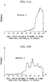
- Fig. 13A shows the case in which the compressing force F is exerted in the vertical direction with respect to the extrusion direction in the extruding step S11, as with the manufacturing method according to this embodiment (material A), and Fig. 13B shows the case in which the compressing force F is exerted in the direction parallel to the extrusion direction (material B).
- Figs. 13A and 13B are histograms in which the lateral axes show deviation angles, with respect to the plate-thickness direction, of normals at the (0001) planes of the compressed metal crystals and the vertical axes show the frequencies.
- the integrated widths of the deviation angles are widths of the deviation angles that fall within a range between 16 % and 84 % of the maximum value of the deviation angles in the cumulative distribution curves in Figs. 13A and 13B .
- the average value of the deviation angle is 16.8° for the material A, whereas the average value of the deviation angle is 26.0° for the material B, thus indicating that a large change occurred in the crystal orientation due to the action of the compressing force F in the material B. Therefore, a product employing a material for which the average value of the deviation angle is equal to or less than 25° is a product in which the compressing force F is exerted in the vertical direction with respect to the extrusion direction, and thus, it is possible to decrease the number of structural defects and to enhance the strength.
- the integrated width of the deviation angle is 17.6° for the material A, whereas the average value of the deviation angle is 25.2° for the material B, and thus, on the basis of this also, it is shown that a large change occurred in the crystal orientation due to the action of the compressing force F in the material B. Therefore, a product employing a material for which the integrated width of the deviation angles is equal to or less than 25° is a product in which the compressing force F is exerted in the vertical direction with respect to the extrusion direction, and thus, it is possible to decrease the number of structural defects and to enhance the strength.
- Fig. 14A and Fig. 14B show histograms showing the relationship between deviation angles of normals at the (0001) planes of metal crystals with respect to the direction parallel to the product surface and frequencies thereof for the material A and the material B, respectively.
- Example 2 compression conditions are varied when exerting the compressing force F on the lump of magnesium-alloy material 2 (WE43) that is suitable for a medical application.
- the lumps of magnesium-alloy material 2 having a diameter of 8 mm and a length of 12 mm were used as samples.
- the heating temperature in the compressing step S13 was changed so as to be 300 °C, 375 °C, and 450 °C; the reduction rate when compressing was changed so as to be 5 mm/s, 0.5 mm/s, and 0.05 mm/s; and results for these cases are shown in Table 3.
- the heating temperature was changed so as to be 350 °C, 400 °C, and 450 °C; the reduction rate when compressing was changed so as to be 1 mm/s, 0.1 mm/s, and 0.01 mm/s; and the results for these cases are shown in Table 4.
- the heating temperature when compressing the lump of magnesium-alloy material 2 be greater than 300 °C, and it is more preferable that the heating temperature be equal to or greater than 350 °C.
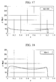
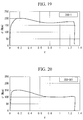
- the relationship between true strain rate ⁇ and load ⁇ is separately shown for the case in which the heating temperature is 375 °C and the reduction rate is 0.05 mm in Fig. 15 , for the case in which the heating temperature is 375 °C and the reduction rate is 5 mm/s in Fig. 16 , for the case in which the heating temperature is 450 °C and the reduction rate is 0.05 mm/s in Fig. 17 , for the case in which the heating temperature is 450 °C and the reduction rate is 5 mm/s in Fig. 18 , for the case in which the heating temperature is 350 °C and the reduction rate is 1 mm/s in Fig. 19 , and for the case in which the heating temperature is 350 °C and the reduction rate is 0.01 mm/s in Fig. 20 .
- re-crystalized grain sizes reach near equilibrium at a true strain rate ⁇ of about 0.6 when the compressing force F is gradually exerted on the lump of magnesium-alloy material 2.
- the reduction ratio is determined to be about 45 %. Because the re-crystalized grain sizes reach near equilibrium at a reduction ratio of about 45 %, by compressing at a reduction ratio equal to or greater than 45 %, it is possible to enhance the corrosion resistance by making the material grain sizes uniform.
- WE43 is considered in this example, magnesium alloys other than WE43 may be considered.
- Fig. 21 shows the relationship between the fraction of fractured surface portions (fraction of fractured surface) at the cut surface formed in the thickness direction and the reduction rate in the punching step S14.
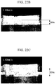
- Figs. 22A to Fig. 22C are photomicrographs of the cut surface when the reduction rate is varied, respectively showing a case in which the reduction rate is 0.24 mm/s ( Fig. 22A ), a case in which the reduction rate is 1.44 mm/s ( Fig. 22B ), and a case in which the reduction rate is 1.92 mm/s ( Fig. 22C ).
- the fraction of fractured surface increases with an increase in the reduction rate, indicating that there is a substantially proportional relationship between the fraction of fractured surface and the reduction rate.
Landscapes
- Health & Medical Sciences (AREA)
- Chemical & Material Sciences (AREA)
- Engineering & Computer Science (AREA)
- Mechanical Engineering (AREA)
- Veterinary Medicine (AREA)
- Public Health (AREA)
- General Health & Medical Sciences (AREA)
- Animal Behavior & Ethology (AREA)
- Life Sciences & Earth Sciences (AREA)
- Vascular Medicine (AREA)
- Heart & Thoracic Surgery (AREA)
- Epidemiology (AREA)
- Oral & Maxillofacial Surgery (AREA)
- Transplantation (AREA)
- Surgery (AREA)
- Organic Chemistry (AREA)
- Metallurgy (AREA)
- Materials Engineering (AREA)
- Biomedical Technology (AREA)
- Orthopedic Medicine & Surgery (AREA)
- Cardiology (AREA)
- Physics & Mathematics (AREA)
- Thermal Sciences (AREA)
- Crystallography & Structural Chemistry (AREA)
- Dermatology (AREA)
- Medicinal Chemistry (AREA)
- Inorganic Chemistry (AREA)
- Materials For Medical Uses (AREA)
- Prostheses (AREA)
- Extrusion Of Metal (AREA)
- Forging (AREA)
Applications Claiming Priority (1)
| Application Number | Priority Date | Filing Date | Title |
|---|---|---|---|
| PCT/JP2013/075635 WO2015044997A1 (ja) | 2013-09-24 | 2013-09-24 | インプラントとその製造方法 |
Publications (2)
| Publication Number | Publication Date |
|---|---|
| EP3050996A1 true EP3050996A1 (de) | 2016-08-03 |
| EP3050996A4 EP3050996A4 (de) | 2017-10-04 |
Family
ID=52742211
Family Applications (1)
| Application Number | Title | Priority Date | Filing Date |
|---|---|---|---|
| EP13894102.6A Withdrawn EP3050996A4 (de) | 2013-09-24 | 2013-09-24 | Implantat und herstellungsverfahren dafür |
Country Status (5)
| Country | Link |
|---|---|
| US (1) | US20160199186A1 (de) |
| EP (1) | EP3050996A4 (de) |
| JP (1) | JPWO2015044997A1 (de) |
| CN (1) | CN105555985A (de) |
| WO (1) | WO2015044997A1 (de) |
Cited By (1)
| Publication number | Priority date | Publication date | Assignee | Title |
|---|---|---|---|---|
| WO2021116453A1 (fr) * | 2019-12-12 | 2021-06-17 | Etablissements Maurice Marle | Procede de formage de lopin pour implant |
Families Citing this family (2)
| Publication number | Priority date | Publication date | Assignee | Title |
|---|---|---|---|---|
| JP6164675B2 (ja) * | 2014-09-09 | 2017-07-19 | 国立大学法人神戸大学 | 生体軟組織固定用デバイスおよびその作製方法 |
| US20180029097A1 (en) * | 2016-10-05 | 2018-02-01 | Ghader Faraji | Hydrostatic cyclic expansion extrusion process for producing ultrafine-grained rods |
Family Cites Families (10)
| Publication number | Priority date | Publication date | Assignee | Title |
|---|---|---|---|---|
| JP3525439B2 (ja) * | 1992-03-04 | 2004-05-10 | 日立金属株式会社 | ターゲット部材およびその製造方法 |
| JP4150219B2 (ja) | 2002-06-27 | 2008-09-17 | 松下電器産業株式会社 | 塊状マグネシウム合金材料の塑性加工方法 |
| US8034101B2 (en) * | 2005-11-16 | 2011-10-11 | National Institute For Materials Science | Magnesium-based biodegradable metallic material |
| KR20080113280A (ko) * | 2006-04-28 | 2008-12-29 | 바이오마그네슘 시스템즈 리미티드 | 생물분해성 마그네슘 합금 및 그 용도 |
| JP2009178293A (ja) | 2008-01-30 | 2009-08-13 | Terumo Corp | 医療用インプラント |
| CN101411891B (zh) * | 2008-12-01 | 2012-11-21 | 天津理工大学 | 一种可降解纳米钙磷化合物增强镁锌合金骨折内固定材料 |
| ES2487631T3 (es) * | 2009-10-30 | 2014-08-22 | Acrostak Corp Bvi, Tortola | Dispositivo médico implantable biodegradable formado a partir de un material basado en magnesio superpuro |
| CN101845607B (zh) * | 2009-11-23 | 2014-03-12 | 北京有色金属研究总院 | 镁合金强韧化变形加工方法 |
| GB201005031D0 (en) * | 2010-03-25 | 2010-05-12 | Magnesium Elektron Ltd | Magnesium alloys containing heavy rare earths |
| CN103243283B (zh) * | 2013-05-27 | 2015-10-07 | 中国科学院长春应用化学研究所 | 超细晶稀土镁合金的制备方法 |
-
2013
- 2013-09-24 CN CN201380079687.6A patent/CN105555985A/zh active Pending
- 2013-09-24 JP JP2015538650A patent/JPWO2015044997A1/ja active Pending
- 2013-09-24 WO PCT/JP2013/075635 patent/WO2015044997A1/ja not_active Ceased
- 2013-09-24 EP EP13894102.6A patent/EP3050996A4/de not_active Withdrawn
-
2016
- 2016-03-17 US US15/072,406 patent/US20160199186A1/en not_active Abandoned
Cited By (2)
| Publication number | Priority date | Publication date | Assignee | Title |
|---|---|---|---|---|
| WO2021116453A1 (fr) * | 2019-12-12 | 2021-06-17 | Etablissements Maurice Marle | Procede de formage de lopin pour implant |
| FR3104407A1 (fr) * | 2019-12-12 | 2021-06-18 | Etablissements Maurice Marle | Procede de formage de lopin pour implant |
Also Published As
| Publication number | Publication date |
|---|---|
| US20160199186A1 (en) | 2016-07-14 |
| CN105555985A (zh) | 2016-05-04 |
| EP3050996A4 (de) | 2017-10-04 |
| WO2015044997A1 (ja) | 2015-04-02 |
| JPWO2015044997A1 (ja) | 2017-03-02 |
Similar Documents
| Publication | Publication Date | Title |
|---|---|---|
| Pachla et al. | Nanocrystalline titanium produced by hydrostatic extrusion | |
| JP5758204B2 (ja) | チタン合金部材およびその製造方法 | |
| TWI425101B (zh) | Cu-Ni-Si alloy excellent in bending workability | |
| Tesař et al. | Direct extrusion of thin Mg wires for biomedical applications | |
| JP6737686B2 (ja) | 純チタン金属ワイヤおよびその加工方法 | |
| Tsao et al. | Flow stress behavior of commercial pure titanium sheet during warm tensile deformation | |
| JP5050199B2 (ja) | マグネシウム合金材料製造方法及び装置並びにマグネシウム合金材料 | |
| TW201718895A (zh) | 鎳-鈦合金之熱機械處理 | |
| US20160199186A1 (en) | Implant and method of manufacturing the same | |
| US10400321B1 (en) | Preparation of nanostructured titanium | |
| CN104769139B (zh) | Cu‑Be合金及其制造方法 | |
| CN105579168A (zh) | 液相烧结铝合金部件的制造方法以及液相烧结铝合金部件 | |
| Meng et al. | Deformation behavior and microstructure evolution in thermal-aided mesoforming of titanium dental abutment | |
| KR20060003908A (ko) | 마그네슘기 합금 성형체의 제조방법 | |
| KR101822740B1 (ko) | 구리 합금판 및 그것을 구비하는 프레스 성형품 | |
| Wang et al. | Effects of lubrication and strain path on constrained groove pressing of commercially pure aluminum sheets | |
| JP2021102225A (ja) | 純チタン金属材料の加工方法 | |
| JP5959260B2 (ja) | マグネシウム合金製インプラントの加工方法 | |
| EP2287352A1 (de) | Verfahren zur herstellung von magnesiumlegierungsmaterial | |
| CN103619506B (zh) | 镁合金材料制造方法及镁合金制棒材 | |
| EP3604574A1 (de) | Kupferlegierungsband mit verbesserter formgenauigkeit nach einer pressbearbeitung | |
| Huang | Effects of grain size on shift of neutral layer of AZ31 magnesium alloy under warm condition | |
| Derakhshandeh et al. | Microstructure and mechanical properties of ultrafine-grained titanium processed by multi-pass ECAP at room temperature using core–sheath method | |
| Mostaed et al. | Microstructural, texture, plastic anisotropy and superplasticity development of ZK60 alloy during equal channel angular extrusion processing | |
| WO2012169304A1 (ja) | チタン合金部材およびその製造方法 |
Legal Events
| Date | Code | Title | Description |
|---|---|---|---|
| PUAI | Public reference made under article 153(3) epc to a published international application that has entered the european phase |
Free format text: ORIGINAL CODE: 0009012 |
|
| 17P | Request for examination filed |
Effective date: 20160412 |
|
| AK | Designated contracting states |
Kind code of ref document: A1 Designated state(s): AL AT BE BG CH CY CZ DE DK EE ES FI FR GB GR HR HU IE IS IT LI LT LU LV MC MK MT NL NO PL PT RO RS SE SI SK SM TR |
|
| AX | Request for extension of the european patent |
Extension state: BA ME |
|
| RAP1 | Party data changed (applicant data changed or rights of an application transferred) |
Owner name: OLYMPUS CORPORATION |
|
| RAP1 | Party data changed (applicant data changed or rights of an application transferred) |
Owner name: OLYMPUS CORPORATION |
|
| RIN1 | Information on inventor provided before grant (corrected) |
Inventor name: SAKAMOTO, TAKAMITSU Inventor name: CYATANI, MASAHIRO Inventor name: TAMAI, MASATO Inventor name: YAMANAKA, SHIGERU Inventor name: HIBI, GENKI |
|
| DAX | Request for extension of the european patent (deleted) | ||
| RIC1 | Information provided on ipc code assigned before grant |
Ipc: C22F 1/06 20060101AFI20170428BHEP Ipc: A61L 27/00 20060101ALI20170428BHEP Ipc: C22C 23/06 20060101ALI20170428BHEP Ipc: C23G 1/12 20060101ALI20170428BHEP Ipc: C22F 1/00 20060101ALI20170428BHEP Ipc: B21K 1/76 20060101ALI20170428BHEP Ipc: B21J 5/00 20060101ALI20170428BHEP Ipc: B21C 23/00 20060101ALI20170428BHEP Ipc: A61F 2/28 20060101ALI20170428BHEP Ipc: B21C 23/08 20060101ALI20170428BHEP |
|
| A4 | Supplementary search report drawn up and despatched |
Effective date: 20170906 |
|
| RIC1 | Information provided on ipc code assigned before grant |
Ipc: B21K 1/76 20060101ALI20170831BHEP Ipc: C23G 1/12 20060101ALI20170831BHEP Ipc: C22C 23/06 20060101ALI20170831BHEP Ipc: B21C 23/00 20060101ALI20170831BHEP Ipc: A61F 2/28 20060101ALI20170831BHEP Ipc: B21C 23/08 20060101ALI20170831BHEP Ipc: C22F 1/06 20060101AFI20170831BHEP Ipc: B21J 5/00 20060101ALI20170831BHEP Ipc: A61L 27/00 20060101ALI20170831BHEP Ipc: C22F 1/00 20060101ALI20170831BHEP |
|
| STAA | Information on the status of an ep patent application or granted ep patent |
Free format text: STATUS: REQUEST FOR EXAMINATION WAS MADE |
|
| STAA | Information on the status of an ep patent application or granted ep patent |
Free format text: STATUS: THE APPLICATION IS DEEMED TO BE WITHDRAWN |
|
| 18D | Application deemed to be withdrawn |
Effective date: 20180404 |