EP3051002A1 - Vorrichtung und verfahren zur herstellung eines films - Google Patents
Vorrichtung und verfahren zur herstellung eines films Download PDFInfo
- Publication number
- EP3051002A1 EP3051002A1 EP15156678.3A EP15156678A EP3051002A1 EP 3051002 A1 EP3051002 A1 EP 3051002A1 EP 15156678 A EP15156678 A EP 15156678A EP 3051002 A1 EP3051002 A1 EP 3051002A1
- Authority
- EP
- European Patent Office
- Prior art keywords
- mist
- film forming
- film
- droplets
- carrier gas
- Prior art date
- Legal status (The legal status is an assumption and is not a legal conclusion. Google has not performed a legal analysis and makes no representation as to the accuracy of the status listed.)
- Withdrawn
Links
Images




Classifications
-
- C—CHEMISTRY; METALLURGY
- C23—COATING METALLIC MATERIAL; COATING MATERIAL WITH METALLIC MATERIAL; CHEMICAL SURFACE TREATMENT; DIFFUSION TREATMENT OF METALLIC MATERIAL; COATING BY VACUUM EVAPORATION, BY SPUTTERING, BY ION IMPLANTATION OR BY CHEMICAL VAPOUR DEPOSITION, IN GENERAL; INHIBITING CORROSION OF METALLIC MATERIAL OR INCRUSTATION IN GENERAL
- C23C—COATING METALLIC MATERIAL; COATING MATERIAL WITH METALLIC MATERIAL; SURFACE TREATMENT OF METALLIC MATERIAL BY DIFFUSION INTO THE SURFACE, BY CHEMICAL CONVERSION OR SUBSTITUTION; COATING BY VACUUM EVAPORATION, BY SPUTTERING, BY ION IMPLANTATION OR BY CHEMICAL VAPOUR DEPOSITION, IN GENERAL
- C23C16/00—Chemical coating by decomposition of gaseous compounds, without leaving reaction products of surface material in the coating, i.e. chemical vapour deposition [CVD] processes
- C23C16/44—Chemical coating by decomposition of gaseous compounds, without leaving reaction products of surface material in the coating, i.e. chemical vapour deposition [CVD] processes characterised by the method of coating
- C23C16/455—Chemical coating by decomposition of gaseous compounds, without leaving reaction products of surface material in the coating, i.e. chemical vapour deposition [CVD] processes characterised by the method of coating characterised by the method used for introducing gases into reaction chamber or for modifying gas flows in reaction chamber
- C23C16/45502—Flow conditions in reaction chamber
- C23C16/45508—Radial flow
-
- C—CHEMISTRY; METALLURGY
- C23—COATING METALLIC MATERIAL; COATING MATERIAL WITH METALLIC MATERIAL; CHEMICAL SURFACE TREATMENT; DIFFUSION TREATMENT OF METALLIC MATERIAL; COATING BY VACUUM EVAPORATION, BY SPUTTERING, BY ION IMPLANTATION OR BY CHEMICAL VAPOUR DEPOSITION, IN GENERAL; INHIBITING CORROSION OF METALLIC MATERIAL OR INCRUSTATION IN GENERAL
- C23C—COATING METALLIC MATERIAL; COATING MATERIAL WITH METALLIC MATERIAL; SURFACE TREATMENT OF METALLIC MATERIAL BY DIFFUSION INTO THE SURFACE, BY CHEMICAL CONVERSION OR SUBSTITUTION; COATING BY VACUUM EVAPORATION, BY SPUTTERING, BY ION IMPLANTATION OR BY CHEMICAL VAPOUR DEPOSITION, IN GENERAL
- C23C16/00—Chemical coating by decomposition of gaseous compounds, without leaving reaction products of surface material in the coating, i.e. chemical vapour deposition [CVD] processes
- C23C16/44—Chemical coating by decomposition of gaseous compounds, without leaving reaction products of surface material in the coating, i.e. chemical vapour deposition [CVD] processes characterised by the method of coating
- C23C16/448—Chemical coating by decomposition of gaseous compounds, without leaving reaction products of surface material in the coating, i.e. chemical vapour deposition [CVD] processes characterised by the method of coating characterised by the method used for generating reactive gas streams, e.g. by evaporation or sublimation of precursor materials
-
- B—PERFORMING OPERATIONS; TRANSPORTING
- B05—SPRAYING OR ATOMISING IN GENERAL; APPLYING FLUENT MATERIALS TO SURFACES, IN GENERAL
- B05B—SPRAYING APPARATUS; ATOMISING APPARATUS; NOZZLES
- B05B17/00—Apparatus for spraying or atomising liquids or other fluent materials, not covered by the preceding groups
- B05B17/04—Apparatus for spraying or atomising liquids or other fluent materials, not covered by the preceding groups operating with special methods
- B05B17/06—Apparatus for spraying or atomising liquids or other fluent materials, not covered by the preceding groups operating with special methods using ultrasonic or other kinds of vibrations
- B05B17/0607—Apparatus for spraying or atomising liquids or other fluent materials, not covered by the preceding groups operating with special methods using ultrasonic or other kinds of vibrations generated by electrical means, e.g. piezoelectric transducers
- B05B17/0615—Apparatus for spraying or atomising liquids or other fluent materials, not covered by the preceding groups operating with special methods using ultrasonic or other kinds of vibrations generated by electrical means, e.g. piezoelectric transducers spray being produced at the free surface of the liquid or other fluent material in a container and subjected to the vibrations
-
- C—CHEMISTRY; METALLURGY
- C23—COATING METALLIC MATERIAL; COATING MATERIAL WITH METALLIC MATERIAL; CHEMICAL SURFACE TREATMENT; DIFFUSION TREATMENT OF METALLIC MATERIAL; COATING BY VACUUM EVAPORATION, BY SPUTTERING, BY ION IMPLANTATION OR BY CHEMICAL VAPOUR DEPOSITION, IN GENERAL; INHIBITING CORROSION OF METALLIC MATERIAL OR INCRUSTATION IN GENERAL
- C23C—COATING METALLIC MATERIAL; COATING MATERIAL WITH METALLIC MATERIAL; SURFACE TREATMENT OF METALLIC MATERIAL BY DIFFUSION INTO THE SURFACE, BY CHEMICAL CONVERSION OR SUBSTITUTION; COATING BY VACUUM EVAPORATION, BY SPUTTERING, BY ION IMPLANTATION OR BY CHEMICAL VAPOUR DEPOSITION, IN GENERAL
- C23C16/00—Chemical coating by decomposition of gaseous compounds, without leaving reaction products of surface material in the coating, i.e. chemical vapour deposition [CVD] processes
- C23C16/44—Chemical coating by decomposition of gaseous compounds, without leaving reaction products of surface material in the coating, i.e. chemical vapour deposition [CVD] processes characterised by the method of coating
- C23C16/4412—Details relating to the exhausts, e.g. pumps, filters, scrubbers, particle traps
-
- C—CHEMISTRY; METALLURGY
- C23—COATING METALLIC MATERIAL; COATING MATERIAL WITH METALLIC MATERIAL; CHEMICAL SURFACE TREATMENT; DIFFUSION TREATMENT OF METALLIC MATERIAL; COATING BY VACUUM EVAPORATION, BY SPUTTERING, BY ION IMPLANTATION OR BY CHEMICAL VAPOUR DEPOSITION, IN GENERAL; INHIBITING CORROSION OF METALLIC MATERIAL OR INCRUSTATION IN GENERAL
- C23C—COATING METALLIC MATERIAL; COATING MATERIAL WITH METALLIC MATERIAL; SURFACE TREATMENT OF METALLIC MATERIAL BY DIFFUSION INTO THE SURFACE, BY CHEMICAL CONVERSION OR SUBSTITUTION; COATING BY VACUUM EVAPORATION, BY SPUTTERING, BY ION IMPLANTATION OR BY CHEMICAL VAPOUR DEPOSITION, IN GENERAL
- C23C16/00—Chemical coating by decomposition of gaseous compounds, without leaving reaction products of surface material in the coating, i.e. chemical vapour deposition [CVD] processes
- C23C16/44—Chemical coating by decomposition of gaseous compounds, without leaving reaction products of surface material in the coating, i.e. chemical vapour deposition [CVD] processes characterised by the method of coating
- C23C16/448—Chemical coating by decomposition of gaseous compounds, without leaving reaction products of surface material in the coating, i.e. chemical vapour deposition [CVD] processes characterised by the method of coating characterised by the method used for generating reactive gas streams, e.g. by evaporation or sublimation of precursor materials
- C23C16/4486—Chemical coating by decomposition of gaseous compounds, without leaving reaction products of surface material in the coating, i.e. chemical vapour deposition [CVD] processes characterised by the method of coating characterised by the method used for generating reactive gas streams, e.g. by evaporation or sublimation of precursor materials by producing an aerosol and subsequent evaporation of the droplets or particles
-
- C—CHEMISTRY; METALLURGY
- C23—COATING METALLIC MATERIAL; COATING MATERIAL WITH METALLIC MATERIAL; CHEMICAL SURFACE TREATMENT; DIFFUSION TREATMENT OF METALLIC MATERIAL; COATING BY VACUUM EVAPORATION, BY SPUTTERING, BY ION IMPLANTATION OR BY CHEMICAL VAPOUR DEPOSITION, IN GENERAL; INHIBITING CORROSION OF METALLIC MATERIAL OR INCRUSTATION IN GENERAL
- C23C—COATING METALLIC MATERIAL; COATING MATERIAL WITH METALLIC MATERIAL; SURFACE TREATMENT OF METALLIC MATERIAL BY DIFFUSION INTO THE SURFACE, BY CHEMICAL CONVERSION OR SUBSTITUTION; COATING BY VACUUM EVAPORATION, BY SPUTTERING, BY ION IMPLANTATION OR BY CHEMICAL VAPOUR DEPOSITION, IN GENERAL
- C23C16/00—Chemical coating by decomposition of gaseous compounds, without leaving reaction products of surface material in the coating, i.e. chemical vapour deposition [CVD] processes
- C23C16/44—Chemical coating by decomposition of gaseous compounds, without leaving reaction products of surface material in the coating, i.e. chemical vapour deposition [CVD] processes characterised by the method of coating
- C23C16/455—Chemical coating by decomposition of gaseous compounds, without leaving reaction products of surface material in the coating, i.e. chemical vapour deposition [CVD] processes characterised by the method of coating characterised by the method used for introducing gases into reaction chamber or for modifying gas flows in reaction chamber
- C23C16/45502—Flow conditions in reaction chamber
-
- C—CHEMISTRY; METALLURGY
- C23—COATING METALLIC MATERIAL; COATING MATERIAL WITH METALLIC MATERIAL; CHEMICAL SURFACE TREATMENT; DIFFUSION TREATMENT OF METALLIC MATERIAL; COATING BY VACUUM EVAPORATION, BY SPUTTERING, BY ION IMPLANTATION OR BY CHEMICAL VAPOUR DEPOSITION, IN GENERAL; INHIBITING CORROSION OF METALLIC MATERIAL OR INCRUSTATION IN GENERAL
- C23C—COATING METALLIC MATERIAL; COATING MATERIAL WITH METALLIC MATERIAL; SURFACE TREATMENT OF METALLIC MATERIAL BY DIFFUSION INTO THE SURFACE, BY CHEMICAL CONVERSION OR SUBSTITUTION; COATING BY VACUUM EVAPORATION, BY SPUTTERING, BY ION IMPLANTATION OR BY CHEMICAL VAPOUR DEPOSITION, IN GENERAL
- C23C16/00—Chemical coating by decomposition of gaseous compounds, without leaving reaction products of surface material in the coating, i.e. chemical vapour deposition [CVD] processes
- C23C16/44—Chemical coating by decomposition of gaseous compounds, without leaving reaction products of surface material in the coating, i.e. chemical vapour deposition [CVD] processes characterised by the method of coating
- C23C16/455—Chemical coating by decomposition of gaseous compounds, without leaving reaction products of surface material in the coating, i.e. chemical vapour deposition [CVD] processes characterised by the method of coating characterised by the method used for introducing gases into reaction chamber or for modifying gas flows in reaction chamber
- C23C16/45502—Flow conditions in reaction chamber
- C23C16/45506—Turbulent flow
-
- C—CHEMISTRY; METALLURGY
- C23—COATING METALLIC MATERIAL; COATING MATERIAL WITH METALLIC MATERIAL; CHEMICAL SURFACE TREATMENT; DIFFUSION TREATMENT OF METALLIC MATERIAL; COATING BY VACUUM EVAPORATION, BY SPUTTERING, BY ION IMPLANTATION OR BY CHEMICAL VAPOUR DEPOSITION, IN GENERAL; INHIBITING CORROSION OF METALLIC MATERIAL OR INCRUSTATION IN GENERAL
- C23C—COATING METALLIC MATERIAL; COATING MATERIAL WITH METALLIC MATERIAL; SURFACE TREATMENT OF METALLIC MATERIAL BY DIFFUSION INTO THE SURFACE, BY CHEMICAL CONVERSION OR SUBSTITUTION; COATING BY VACUUM EVAPORATION, BY SPUTTERING, BY ION IMPLANTATION OR BY CHEMICAL VAPOUR DEPOSITION, IN GENERAL
- C23C16/00—Chemical coating by decomposition of gaseous compounds, without leaving reaction products of surface material in the coating, i.e. chemical vapour deposition [CVD] processes
- C23C16/44—Chemical coating by decomposition of gaseous compounds, without leaving reaction products of surface material in the coating, i.e. chemical vapour deposition [CVD] processes characterised by the method of coating
- C23C16/458—Chemical coating by decomposition of gaseous compounds, without leaving reaction products of surface material in the coating, i.e. chemical vapour deposition [CVD] processes characterised by the method of coating characterised by the method used for supporting substrates in the reaction chamber
- C23C16/4582—Rigid and flat substrates, e.g. plates or discs
- C23C16/4583—Rigid and flat substrates, e.g. plates or discs the substrate being supported substantially horizontally
- C23C16/4586—Elements in the interior of the support, e.g. electrodes, heating or cooling devices
Definitions
- the present invention relates to a novel film forming apparatus and a method which are useful for performing a mist chemical vapor deposition.
- mist chemical vapor deposition (hereafter may be referred to as "mist CVD"), which grows a crystal on a substrate using an atomized raw material (a mist).
- mist CVD has made it possible to form a corundum-structured gallium oxide ( ⁇ -Ga 2 O 3 ).
- ⁇ -Ga 2 O 3 is expected to be applied to next-generation switching devices which can realize a high voltage, a low loss, and a high heat resistance.
- Japanese Unexamined Patent Application Publication No. 1-257337 discloses a tubular-furnace mist CVD apparatus.
- Japanese Unexamined Patent Application Publication No. 2005-307238 discloses a fine-channel mist CVD apparatus.
- Japanese Unexamined Patent Application Publication No. 2012-46772 discloses a liner-source mist CVD apparatus.
- Japanese Patent No. 5397794 discloses a tubular-furnace mist CVD apparatus.
- This mist CVD apparatus differs from that of Japanese Unexamined Patent Application Publication No. 1-257337 in that a carrier gas is introduced into a mist generator.
- Japanese Unexamined Patent Application Publication No. 2014-63973 discloses a mist CVD apparatus in which a substrate is placed above a mist generator and a susceptor is a rotating stage disposed on a hot plate.
- mist CVD does not require high temperature and allows for formation of a metastable-phase crystal structure like the corundum structure of ⁇ -gallium oxide.
- mist CVD involves growing a crystal without mist droplets directly contacting the film by covering the substrate surface with a mist volatilization layer due to the Leidenfrost effect described in B. S. Gottfried., et al., "Film Boiling of Spheroidal Droplets. Leidenfrost Phenomenon", Ind. Eng. Chem. Fundamen., 1966, 5 (4), pp 561 to 568 .
- Such crystal growth is not easy to control, and a uniform crystal film is difficult to obtain.
- mist CVD there are variations among the mist particles, and the mist sinks down in the supply pipe before reaching the substrate. These problems have led to low film formation rates or the like.
- An object of the present invention is to provide a film forming apparatus and method which are excellent in the film formation rate and are useful for performing mist CVD.
- the inventors intensively conducted research to accomplish the above object and then succeeded in forming a mist CVD apparatus in which a film forming unit includes means configured to swirl a mist or droplets to generate a swirling flow.
- a film forming unit includes means configured to swirl a mist or droplets to generate a swirling flow.
- the film forming apparatus and method of the present invention are useful for performing mist CVD and are excellent in the film formation rate.
- a film forming apparatus of the present invention includes an atomization/ droplet-formation unit for turning a raw material solution into a mist or droplets, a carrying unit for carrying the mist or droplets generated in the atomization/droplet-formation unit onto a base using a carrier gas, and a film forming unit for treating the mist or droplets with heat to form a film on the base.
- the film forming unit includes means configured to swirl the mist or droplets for generating a swirling flow.
- FIG. 1 shows an example of the film forming apparatus of the present invention.
- a film forming apparatus 1 includes a carrier gas source 2a for supplying a carrier gas, a flow rate control valve 3a for controlling the flow rate of the carrier gas sent from the carrier gas source 2a, a dilution carrier gas source 2b for supplying a dilution carrier gas, a flow rate control valve 3b for adjusting the flow rate of the dilution carrier gas sent from the dilution carrier gas source 2b, a mist source 4 containing a raw-material solution 4a, a container 5 containing water 5a, an ultrasonic transducer 6 mounted on the bottom of the container 5, a film forming chamber 7, a supply pipe 9 connecting the mist source 4 to the film forming chamber 7, a hot plate 8 disposed in the film forming chamber 7, an exhaust pipe 17, and an exhaust fan 11.
- a substrate 10 is placed on the hot plate 8.
- the film forming apparatus 1 of the present invention includes an atomization/droplet-formation unit for turning a raw-material solution into the mist or droplets.
- Fig. 2 shows one embodiment of the atomization/droplet-formation unit.
- the mist source 4 is a container containing the raw-material solution 4a.
- the mist source 4 is supported in the container 5, which contains the water 5a, using a supporter (not shown).
- the ultrasonic transducer 6 is mounted on the bottom of the container 5 and connected to an oscillator 16. By operating the oscillator 16, the ultrasonic transducer 6 vibrates to generate ultrasound, which then propagates through the water 5a into the mist source 4, so that the raw-material solution 4a is turned into the mist or droplets.
- Fig. 3 shows one embodiment of the ultrasonic transducer 6 shown in Fig. 2 .
- a disc-shaped piezoelectric element 6b is disposed in a cylindrical elastic object 6d on a supporter 6e, and electrodes 6a and 6c are disposed on both surfaces of the piezoelectric element 6b.
- electrodes 6a and 6c are disposed on both surfaces of the piezoelectric element 6b.
- the atomization/droplet-formation unit prepares a raw-material solution and turns the raw-material solution into the mist or droplets to generate the mist or droplets.
- the atomization/droplet-formation unit is not particularly limited as long as it can turn the raw-material solution into the mist or droplets, and may be known atomization/droplet-formation means.
- the atomization/droplet-formation unit is preferably atomization means or droplet-formation means which uses ultrasonic vibration.
- a carrying unit carries the mist or droplets onto the base using the carrier gas and optionally a supply pipe or the like.
- the type of the carrier gas is not particularly limited as long as the objects of the present invention are not impaired.
- Preferred examples include oxygen, ozone, inert gases such as nitrogen and argon, and reducing gases such as hydrogen gas and forming gas.
- the number of carrier gases may be one, but may be two or more.
- the number of locations for supplying the carrier gas is not limited to one and may be two or more.
- the flow rate of the carrier gas is not particularly limited. However, when forming a film on a 30-mm square substrate, for example, the flow rate is preferably 0.01 to 20L/min, more preferably 1 to 10L/min.
- the film forming unit treats the mist or droplets with heat to cause a thermal reaction, thereby forming a film on part or all of the base surface.
- the thermal reaction is not particularly limited as long as the mist or droplets reacts with heat applied.
- the reaction conditions or the like are also not particularly limited as long as the objects of the present invention are not impaired.
- the heating temperature is typically 120 to 600°C, preferably 120 to 350°C, more preferably 130 to 300°C.
- the thermal reaction may be caused under any of vacuum, a non-oxygen atmosphere, a reducing gas atmosphere, and an oxygen atmosphere as long as the objects of the present invention are not impaired.
- the thermal reaction may be caused under any of an atmospheric pressure, an elevated pressure, and a reduced pressure, but is preferably caused under the atmospheric pressure.
- Fig. 4 shows one embodiment of the film forming unit.
- the film forming chamber 7 of Fig. 4 is cylindrical and is disposed on the hot plate 8.
- the film forming chamber 7 is connected to the mist source 4 via the supply pipe 9. Mist or droplets 4b generated in the mist source 4 is carried through the supply pipe 9 into the film forming chamber 7 by the carrier gas and then thermally reacts on the substrate 10 placed on the hot plate.
- the film forming chamber 7 has an outlet for exhausting the mist or droplets in the center of the ceiling surface (upper surface). The outlet is disposed in a portion more remote from the substrate than an inlet.
- the film forming chamber 7 is connected to an exhaust pipe 17 at the outlet so that the resulting mist or droplets or exhaust gas 4c is exhausted through the exhaust pipe 17.
- the film forming apparatus 1 may further include trapping means configured to trap the resulting mist or droplets, or exhaust gas.
- trapping means configured to trap the resulting mist or droplets, or exhaust gas.
- the swirling flow may flow in any of the inward direction and outward direction. In the present invention, it preferably flows in the inward direction.
- Figs. 8A and 8B are schematic diagrams showing the flow of the mist or droplets on the substrate in the film forming chamber of Fig. 4 .
- Fig. 8A is a sectional view of the cylindrical film forming chamber 7 seen from above. The substrate 10 is placed in the film forming chamber 7, and the flow of the mist or droplets is shown by an arrow. In the film forming chamber of Fig. 4 , the mist or droplets flows toward the center of the substrate while swirling inwardly, that is, there occurs a swirling flow which flows in the direction of an arrow in Fig. 8A.
- Fig. 8A is a sectional view of the cylindrical film forming chamber 7 seen from above. The substrate 10 is placed in the film forming chamber 7, and the flow of the mist or droplets is shown by an arrow. In the film forming chamber of Fig. 4 ,
- FIG. 8B is a schematic sectional view of the film forming chamber 7 seen from a side, and the substrate 10 is placed in the film forming chamber 7.
- the mist or droplets flows from the outside to the inside.
- the mist or droplets When the mist or droplets reaches near the center of the substrate, the mist or droplets upwardly flows toward the outlet disposed above.
- the base may be in face-down orientation, for example, by placing it on the top surface of the film forming chamber, or may be in face-up orientation by placing it on the bottom surface thereof, as shown in Fig. 4 .
- the means for generating the swirling flow is not particularly limited as long as the objects of the present invention are not impaired, and may be known means.
- the following swirling flow generation means may be employed: a cylindrical film forming chamber is used; a base is placed on the bottom surface or top surface of the chamber; the mist or droplets is introduced from the side of the chamber; and an outlet is formed in a surface opposite to the surface (preferably, the position) having the base placed thereon.
- the mist or droplets is preferably introduced into the film forming chamber in such a manner that the mist or droplets moves along the inner surface of the chamber.
- the inlet is preferably oriented substantially to the direction of a tangent to the inner surface of the film forming chamber.
- the direction of introduction of the mist or droplets is not particularly limited.
- the flow rate of the swirling flow is not particularly limited as long as the objects of the present invention are not impaired, but is preferably 10 to 100cm/s, more preferably 20 to 70cm/s.
- a film forming process using the film forming apparatus 1 of the present invention will be described.
- the raw-material solution 4a is charged into the mist source 4, the substrate 10 is placed on the hot plate 8, and the hot plate 8 is operated. Then, the flow rate control valves 3(3a, 3b) are opened to feed the carrier gas and dilution carrier gas from the carrier-gas sources 2 (2a, 2b) into the film forming chamber 7. After sufficiently substituting the carrier gas and dilution carrier gas for the atmosphere in the film forming chamber 7, the respective flow rates of the carrier gas and dilution carrier gas are adjusted. Subsequently, the ultrasonic transducer 6 is vibrated so that the vibration propagates through the water 5a into the raw-material solution 4a. Thus, the raw-material solution 4a is turned into the mist or droplets 4b.
- the mist or droplets 4b is then carried into the film forming chamber 7 by the carrier gas.
- the film forming chamber 7 has the outlet connected to the exhaust pipe 17 in the center of the top surface thereof.
- the exhaust pipe 17 is connected to the exhaust fan 11, which draws an exhaust gas or the like from the outlet of the film forming chamber 7.
- the cylindrical film forming chamber 7 has the inlet for introducing the mist or droplets in a side surface thereof.
- the mist or droplets introduced into the film forming chamber 7 is swirled to generate an inwardly swirling flow.
- the swirling mist or droplets then thermally reacts with heat generated by the hot plate 8 in the film forming chamber 7, thereby forming a film on the substrate 10.
- the shape of the film forming chamber is not particularly limited as long as the objects of the present invention are not impaired, but is preferably tubular.
- the shape of the film forming chamber may be cylindrical, almost cylindrical, prismatic (e.g., cubic, rectangular parallelepiped-shaped, pentagonal prism-shaped, hexagonal prism-shaped, octagonal prism-shaped, or the like), or almost prismatic, but is preferably cylindrical or almost cylindrical in the present invention.
- the base may be rotated during formation of a film, and the rotation direction is preferably opposite to the direction of the swirling flow.
- the raw-material solution is not particularly limited as long as it contains a raw material which can be turned into the mist or droplets.
- a raw material may be inorganic or organic.
- the raw material is preferably a metal or metal compound, more preferably contains one or two metals selected from gallium, iron, indium, aluminum, vanadium, titanium, chromium, rhodium, nickel, and cobalt.
- the raw-material solution is not particularly limited as long as the metal can be turned into the mist or droplets.
- the raw-material solution is one obtained by dissolving or dispersing the metal taking the form of a complex or salt in an organic solvent or water.
- the complex form include acetylacetonate complex, carbonyl complex, ammine complex, and hydrido complex.
- the salt form include metal chloride salts, metal bromide salts, and metal iodide salts.
- the raw-material solution may contain an additive such as halide acid or oxidant.
- halide acid include hydrobromic acid, hydrochloric acid, and hydroiodic acid.
- hydrobromic acid and hydroiodic acid are preferred.
- oxidant include peroxides such as hydrogen peroxide (H 2 O 2 ), sodium peroxide (Na 2 O 2 ), barium peroxide (BaO 2 ), and benzoyl peroxide(CeH 5 CO) 2 O 2 and organic peroxides such as hypochlorous acid (HClO), perchloric acid, nitric acid, ozone water, peracetic acid, and nitrobenzene.
- H 2 O 2 hydrogen peroxide
- Na 2 O 2 sodium peroxide
- BaO 2 barium peroxide
- organic peroxides such as hypochlorous acid (HClO), perchloric acid, nitric acid, ozone
- the raw-material solution may contain a dopant.
- the type of the dopant is not particularly limited as long as the objects of the present invention are not impaired.
- Examples of the dopant include n-type or p-type dopants, including tin, germanium, silicon, titanium, zirconium, vanadium, and niobium.
- the concentration of the dopant may be about 1 ⁇ 10 16 /cm 3 to 1 ⁇ 10 22 /cm 3 , or may be as low as e.g., about 1 ⁇ 10 17 /cm 3 or less.
- the raw-material solution may also contain a dopant at a high concentration of about 1 ⁇ 10 20 /cm 3 or more.
- the base is not particularly limited as long as it can support the film.
- the material of the base also is not particularly limited as long as the objects of the present invention are not impaired, and may be known bases, organic compounds, or inorganic compounds.
- the base may be in any shape, including plates such as a flat plate and disc, a fiber, a bar, a cylinder, a prism, a tube, a spiral, a sphere, and a ring.
- the base is preferably in the shape of a substrate.
- the thickness of the substrate is not particularly limited in the present invention, but is preferably 10 to 2000 ⁇ m, more preferably 50 to 800 ⁇ m.
- the film forming apparatus 1 includes the carrier gas source 2a for supplying a carrier gas, the flow rate control valve 3a for controlling the flow rate of the carrier gas sent from the carrier gas source 2a, the dilution carrier gas source 2b for supplying a dilution carrier gas, the flow rate control valve 3b for controlling the flow rate of the dilution carrier gas sent from the dilution carrier gas source 2b, the mist source 4 containing the raw-material solution 4a, the container 5 containing the water 5a, the ultrasonic transducer 6 mounted on the bottom of the container 5, the film forming chamber 7, the quartz supply pipe 9 connecting the mist source 4a to the film forming chamber 7, the hot plate 8 mounted in the film forming chamber 7, the exhaust pipe 17, and the exhaust fan 11.
- the substrate 10 is placed on the hot plate 8.
- the raw-material solution 4a obtained in the above 2. was charged into the mist source 4. Then, a 4-inch c-plane sapphire substrate serving as the substrate 10 was placed on the hot plate 8, which was then operated to increase the temperature in the film forming chamber 7 to 500°C. Then, the flow rate control valves 3 (3a, 3b) were opened to feed the carrier gas and dilution carrier gas from the carrier-gas sources 2 (2a, 2b) into the film forming chamber 7. After sufficiently substituting the carrier gas and dilution carrier gas for the atmosphere in the film forming chamber 7, the flow rates of the carrier gas and dilution carrier gas were adjusted to 5L/min and 0.5L/min, respectively. Oxygen was used as the carrier gas.
- the ultrasonic transducer 6 was vibrated at 2.4 MHz so that the vibration propagated through the water 5a into the raw-material solution 4a.
- the raw-material solution 4a was atomized into the mist 4b.
- the mist 4b was carried into the film forming chamber 7 by the carrier gas and then swirled therein, thereby generating an inwardly swirling flow as shown in Fig. 8 .
- the swirling mist then made a reaction under atmospheric pressure and at 560°C in the film forming chamber 7, thereby forming a thin film on the substrate 10.
- the flow rate of the mist was 45.6cm/s, and the film formation time was 30 min.
- the phase of the ⁇ -Ga 2 O 3 thin film obtained in the above 4. was identified. The identification was made by 2 ⁇ / ⁇ ) scanning the thin film at angles of 15 to 95 degrees using an XRD diffractometer for thin films. Then, a measurement was made using CuK ⁇ rays. As a result, the thin film was found to be ⁇ -Ga 2 O 3 .
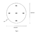
- the thicknesses of measurement positions A1, A2, A3, A4, and A5 of the thin film on the substrate 10 shown in Fig. 5 were measured using a step gauge, and the thicknesses measured were averaged to obtain an average thickness of 3,960 nm. The average thickness was divided by the film formation time to obtain a film formation rate of 132 nm/min.
- the mist CVD apparatus 19 includes a susceptor 21 having a substrate 20 placed thereon, carrier gas supply means 22a for supplying a carrier gas, a flow rate control valve 23a for controlling the flow rate of the carrier gas sent from the carrier gas supply means 22a, dilution carrier gas supply means 22b for supplying a dilution carrier gas, a flow rate control valve 23b for controlling the flow rate of the dilution carrier gas sent from the dilution carrier gas supply means 22b, a mist source 24 containing a raw-material solution 24a, a container 25 containing water 25a, an ultrasonic transducer 26 mounted on the bottom of the container 25, a supply pipe 27 made of a 40 mm-inner diameter quartz tube, a heater 28 disposed around the supply pipe 27, and an outlet 29.
- the susceptor 21 is formed of quartz, and the surface having the substrate 20 placed thereon is inclined from the horizontal plane by 45 degrees. By forming both the supply pipe 27 and susceptor 21 serving as a film forming chamber from quartz, entry of apparatus-derived impurities into a film formed on the substrate 20 is reduced.
- Example 1 A film was formed as in Example 1 except that the film forming apparatus shown in Fig. 6 was used and a 10 mm square c-plane sapphire substrate was used as the substrate 20.
- the phase of the obtained thin film was identified using an XRD diffractometer for thin films, as in Example 1.
- the obtained thin film was found to be ⁇ -Ga 2 O 3 .
- the thicknesses of the thin film were measured as in the Example. Specifically, the thicknesses of measurement positions B1, B2, B3, B4, and B5 of the thin film on the substrate 20 shown in Fig. 7 were measured. The measurement results are shown as Comparative Example in Table 1.
- Example 1 A film was formed as in Example 1 except that a 10-mm square c-plane sapphire was used as the substrate 10.
- the phase of the obtained thin film was identified using an XRD diffractometer for thin films, as in Comparative Example.
- the obtained thin film was found to be ⁇ -Ga 2 O 3 .
- the thicknesses thereof were measured as in Comparative Example. Specifically, the thicknesses of measurement positions B1, B2, B3, B4, and B5 of the thin film were measured as in Comparative Example except that the substrate 10 was used in place of the substrate 20.
- the measurement results are shown as Example 2 in Table 1.
- Example 2 (substrate: 10 mm square) Comparative Example (substrate: 10 mm square) B1 3,902 674 B2 4,311 499 B3 4,010 593 B4 3,869 809 B5 3,698 552
- the average thickness, film formation rate, variation coefficient and in-plane uniformity of each Example were obtained from the results in Table 1.
- the results are shown in Table 2.
- the average thickness is the average of the film thicknesses of the measurement positions;
- the film formation rate is a value obtained by dividing the average film thickness by the film formation time (min);
- the variation coefficient is a coefficient obtained by dividing the standard deviation of the film thicknesses by the average thickness;
- the in-plane uniformity indicates the variation range by expressing the difference between the average thickness and the largest or smallest thickness in percentage.
- Example 2 (substrate: 10 mm square) Comparative Example (substrate: 10 mm square) Average film thickness 3,958 nm 625 nm Film formation rate 132 nm/min 21 nm/min Variation coefficient 0.05 0.17 In-plane uniformity -7% to +9% -20% to +29%
- Example 2 As are apparent in Tables 1 and 2, the film formation rate of Example 2 is incomparably higher than that of Comparative Example, and there are also clear differences in film forming quality such as in-plane uniformity between the Examples. As seen above, the film forming apparatus and method of the present invention are excellent in the film formation rate, film thickness uniformity, and the like, compared to the traditional mist CVD apparatus.
- An aqueous solution was prepared such that the molar ratio between gallium acetylacetonate and aluminum acetylacetonate was 1:6 and the volume percentage of hydrochloric acid was 2% to give a raw-material solution.
- a film was formed as in Example 1 except that the raw-material solution obtained was used; the film forming temperature was 600°C; the flow rate of the carrier gas was 8 LPM; and the film formation time was 3 h. The flow rate of the mist was 73.0cm/s.
- the aluminum content of the film obtained was measured using X rays.
- the XRD measurement results are shown in Fig. 9 .
- the XRD measurement results indicate that the film obtained was a corundum-structured, 62.8%-aluminum-containing, AlGaO-based semiconductor film, which has been deemed difficult to form. Further, the thickness of the corundum-structured AlGaO-based semiconductor film was measured and found to be 720 nm.
- the traditional art allows for formation of a corundum-structured AlGaO-based semiconductor film, it does not allow for formation of such a film which is 50 nm or more thick.
- the present invention allows for formation of a corundum-structured AlGaO-based semiconductor film which is as thick as 700 nm or more.
- This Example also reveals that the film forming apparatus of the present invention is excellent in the suitability for mist CVD, as well as incomparably excellent in the film formation rate.
- the film forming apparatus and method of the present invention are applicable to all film forming fields and industrially useful.
- the film forming apparatus and method of the present invention can be suitably used in forming a film by mist CVD.
Landscapes
- Chemical & Material Sciences (AREA)
- Metallurgy (AREA)
- Chemical Kinetics & Catalysis (AREA)
- Engineering & Computer Science (AREA)
- Materials Engineering (AREA)
- Mechanical Engineering (AREA)
- General Chemical & Material Sciences (AREA)
- Organic Chemistry (AREA)
- Physics & Mathematics (AREA)
- Fluid Mechanics (AREA)
- Dispersion Chemistry (AREA)
- Chemical Vapour Deposition (AREA)
- Crystals, And After-Treatments Of Crystals (AREA)
Applications Claiming Priority (2)
| Application Number | Priority Date | Filing Date | Title |
|---|---|---|---|
| JP2015015217 | 2015-01-29 | ||
| JP2015023488A JP6478103B2 (ja) | 2015-01-29 | 2015-02-09 | 成膜装置および成膜方法 |
Publications (1)
| Publication Number | Publication Date |
|---|---|
| EP3051002A1 true EP3051002A1 (de) | 2016-08-03 |
Family
ID=52596373
Family Applications (1)
| Application Number | Title | Priority Date | Filing Date |
|---|---|---|---|
| EP15156678.3A Withdrawn EP3051002A1 (de) | 2015-01-29 | 2015-02-26 | Vorrichtung und verfahren zur herstellung eines films |
Country Status (2)
| Country | Link |
|---|---|
| US (1) | US20160222511A1 (de) |
| EP (1) | EP3051002A1 (de) |
Families Citing this family (11)
| Publication number | Priority date | Publication date | Assignee | Title |
|---|---|---|---|---|
| US10989609B2 (en) | 2017-05-09 | 2021-04-27 | Flosfia Inc. | Thermistor film and method of depositing the same |
| JP6875336B2 (ja) | 2018-08-27 | 2021-05-26 | 信越化学工業株式会社 | 成膜方法 |
| JP7031564B2 (ja) * | 2018-11-14 | 2022-03-08 | トヨタ自動車株式会社 | 燃料電池用セパレータの製造方法 |
| JP6934852B2 (ja) * | 2018-12-18 | 2021-09-15 | 信越化学工業株式会社 | 酸化ガリウム膜の製造方法 |
| JP7216371B2 (ja) * | 2019-06-05 | 2023-02-01 | 株式会社デンソー | 酸化物膜の成膜方法、半導体装置の製造方法、及び、酸化物膜の成膜装置 |
| JP7212890B2 (ja) * | 2019-06-05 | 2023-01-26 | 株式会社デンソー | 酸化物膜の成膜方法、半導体装置の製造方法、及び、酸化物膜の成膜装置 |
| CN115428131B (zh) * | 2020-04-13 | 2025-08-29 | 信越化学工业株式会社 | 成膜装置及成膜方法 |
| TW202146701A (zh) * | 2020-05-26 | 2021-12-16 | 荷蘭商Asm Ip私人控股有限公司 | 氣相沉積系統、在基材上形成氮化釩層之方法、直接液體注入系統 |
| JP6925548B1 (ja) | 2020-07-08 | 2021-08-25 | 信越化学工業株式会社 | 酸化ガリウム半導体膜の製造方法及び成膜装置 |
| WO2022045629A1 (ko) * | 2020-08-25 | 2022-03-03 | 주성엔지니어링(주) | 기판 처리 장치 |
| TWM633563U (zh) | 2021-03-02 | 2022-11-01 | 日商信越化學工業股份有限公司 | 製膜系統及製膜裝置 |
Citations (9)
| Publication number | Priority date | Publication date | Assignee | Title |
|---|---|---|---|---|
| JPH01257337A (ja) | 1988-04-06 | 1989-10-13 | Fujitsu Ltd | 気相エピタキシャル成長装置 |
| US6349668B1 (en) * | 1998-04-27 | 2002-02-26 | Msp Corporation | Method and apparatus for thin film deposition on large area substrates |
| US20040028810A1 (en) * | 2000-10-16 | 2004-02-12 | Primaxx, Inc. | Chemical vapor deposition reactor and method for utilizing vapor vortex |
| JP2005307238A (ja) | 2004-04-19 | 2005-11-04 | Shizuo Fujita | 成膜方法及び成膜装置 |
| US20080022928A1 (en) * | 2006-07-28 | 2008-01-31 | Masakazu Sanada | Substrate processing apparatus |
| JP2012046772A (ja) | 2010-08-24 | 2012-03-08 | Sharp Corp | ミストcvd装置及びミスト発生方法 |
| JP5397794B1 (ja) | 2013-06-04 | 2014-01-22 | Roca株式会社 | 酸化物結晶薄膜の製造方法 |
| JP2014063973A (ja) | 2012-08-26 | 2014-04-10 | Kumamoto Univ | 酸化亜鉛結晶層の製造方法及び酸化亜鉛結晶層並びにミスト化学気相成長装置 |
| EP2752869A1 (de) * | 2012-09-28 | 2014-07-09 | Roca K.K. | Halbleitervorrichtung oder kristall und verfahren zur herstellung der halbleitervorrichtung oder des kristalls |
Family Cites Families (4)
| Publication number | Priority date | Publication date | Assignee | Title |
|---|---|---|---|---|
| US4699082A (en) * | 1983-02-25 | 1987-10-13 | Liburdi Engineering Limited | Apparatus for chemical vapor deposition |
| US5554415A (en) * | 1994-01-18 | 1996-09-10 | Qqc, Inc. | Substrate coating techniques, including fabricating materials on a surface of a substrate |
| US6527833B1 (en) * | 1999-02-02 | 2003-03-04 | Virginia Tech Intellectual Properties, Inc. | Hydrogen-selective silica based membrane |
| JP5573046B2 (ja) * | 2009-08-24 | 2014-08-20 | 富士通株式会社 | 成膜装置及び成膜方法 |
-
2015
- 2015-02-26 EP EP15156678.3A patent/EP3051002A1/de not_active Withdrawn
- 2015-02-26 US US14/632,768 patent/US20160222511A1/en not_active Abandoned
Patent Citations (9)
| Publication number | Priority date | Publication date | Assignee | Title |
|---|---|---|---|---|
| JPH01257337A (ja) | 1988-04-06 | 1989-10-13 | Fujitsu Ltd | 気相エピタキシャル成長装置 |
| US6349668B1 (en) * | 1998-04-27 | 2002-02-26 | Msp Corporation | Method and apparatus for thin film deposition on large area substrates |
| US20040028810A1 (en) * | 2000-10-16 | 2004-02-12 | Primaxx, Inc. | Chemical vapor deposition reactor and method for utilizing vapor vortex |
| JP2005307238A (ja) | 2004-04-19 | 2005-11-04 | Shizuo Fujita | 成膜方法及び成膜装置 |
| US20080022928A1 (en) * | 2006-07-28 | 2008-01-31 | Masakazu Sanada | Substrate processing apparatus |
| JP2012046772A (ja) | 2010-08-24 | 2012-03-08 | Sharp Corp | ミストcvd装置及びミスト発生方法 |
| JP2014063973A (ja) | 2012-08-26 | 2014-04-10 | Kumamoto Univ | 酸化亜鉛結晶層の製造方法及び酸化亜鉛結晶層並びにミスト化学気相成長装置 |
| EP2752869A1 (de) * | 2012-09-28 | 2014-07-09 | Roca K.K. | Halbleitervorrichtung oder kristall und verfahren zur herstellung der halbleitervorrichtung oder des kristalls |
| JP5397794B1 (ja) | 2013-06-04 | 2014-01-22 | Roca株式会社 | 酸化物結晶薄膜の製造方法 |
Non-Patent Citations (1)
| Title |
|---|
| B. S. GOTTFRIED. ET AL.: "Film Boiling of Spheroidal Droplets. Leidenfrost Phenomenon", IND. ENG. CHEM. FUNDAMEN., vol. 5, no. 4, 1966, pages 561 - 568 |
Also Published As
| Publication number | Publication date |
|---|---|
| US20160222511A1 (en) | 2016-08-04 |
Similar Documents
| Publication | Publication Date | Title |
|---|---|---|
| JP6478103B2 (ja) | 成膜装置および成膜方法 | |
| EP3051002A1 (de) | Vorrichtung und verfahren zur herstellung eines films | |
| JP7374282B2 (ja) | ガリウム含有膜の成膜方法 | |
| JP5397794B1 (ja) | 酸化物結晶薄膜の製造方法 | |
| JP7674279B2 (ja) | 成膜装置及び成膜方法 | |
| JP2022016427A (ja) | 酸化ガリウム薄膜及び積層構造体 | |
| JP7803500B2 (ja) | 酸化ガリウム半導体膜の製造方法 | |
| JP6233959B2 (ja) | 酸化物結晶薄膜の製造方法 | |
| Vallejos et al. | Aerosol-assisted chemical vapor deposition of metal oxide structures: Zinc oxide rods | |
| JP6638152B2 (ja) | 蛍光体組成物の製造方法および発光装置 | |
| TW202315968A (zh) | 成膜裝置及使用此成膜裝置的結晶性半導體膜的成膜方法 | |
| JP6867637B2 (ja) | サセプタ | |
| TWI858756B (zh) | 成膜方法 | |
| JP2018070437A (ja) | 結晶性ZrO2膜の製造方法および結晶性ZrO2膜 | |
| JP2016157879A (ja) | 結晶性酸化物半導体膜、半導体装置 | |
| JP2022109309A (ja) | 成膜方法 | |
| JP2016027635A (ja) | 成膜装置および成膜方法 | |
| JP2020047948A (ja) | 結晶性酸化物半導体膜、半導体装置 | |
| JP2021161012A (ja) | サファイア基板の表面処理方法 |
Legal Events
| Date | Code | Title | Description |
|---|---|---|---|
| PUAI | Public reference made under article 153(3) epc to a published international application that has entered the european phase |
Free format text: ORIGINAL CODE: 0009012 |
|
| 17P | Request for examination filed |
Effective date: 20150323 |
|
| AK | Designated contracting states |
Kind code of ref document: A1 Designated state(s): AL AT BE BG CH CY CZ DE DK EE ES FI FR GB GR HR HU IE IS IT LI LT LU LV MC MK MT NL NO PL PT RO RS SE SI SK SM TR |
|
| AX | Request for extension of the european patent |
Extension state: BA ME |
|
| STAA | Information on the status of an ep patent application or granted ep patent |
Free format text: STATUS: EXAMINATION IS IN PROGRESS |
|
| 17Q | First examination report despatched |
Effective date: 20180717 |
|
| STAA | Information on the status of an ep patent application or granted ep patent |
Free format text: STATUS: THE APPLICATION HAS BEEN WITHDRAWN |
|
| 18W | Application withdrawn |
Effective date: 20181019 |