EP3051027A1 - Procédé de mise en place par vibrations et système de mise en place par vibrations - Google Patents
Procédé de mise en place par vibrations et système de mise en place par vibrations Download PDFInfo
- Publication number
- EP3051027A1 EP3051027A1 EP16152736.1A EP16152736A EP3051027A1 EP 3051027 A1 EP3051027 A1 EP 3051027A1 EP 16152736 A EP16152736 A EP 16152736A EP 3051027 A1 EP3051027 A1 EP 3051027A1
- Authority
- EP
- European Patent Office
- Prior art keywords
- vibration device
- pile
- vibration
- mass
- ground
- Prior art date
- Legal status (The legal status is an assumption and is not a legal conclusion. Google has not performed a legal analysis and makes no representation as to the accuracy of the status listed.)
- Granted
Links
Images
Classifications
-
- E—FIXED CONSTRUCTIONS
- E02—HYDRAULIC ENGINEERING; FOUNDATIONS; SOIL SHIFTING
- E02D—FOUNDATIONS; EXCAVATIONS; EMBANKMENTS; UNDERGROUND OR UNDERWATER STRUCTURES
- E02D7/00—Methods or apparatus for placing sheet pile bulkheads, piles, mouldpipes, or other moulds
- E02D7/18—Placing by vibrating
Definitions
- the invention relates to a method for vibratory ramming of pile material in a subsoil, which are introduced by means of a vibrating device attached to the pile high frequency vibrations on the Rammgut in the ground in front of a tread of the pile, so that the ground liquefied before the tread base, causing the pile due its own weight and the weight of the vibration device is driven into the ground.
- Piles in the form of piles, bung profiles or other profiles can be driven by hammering or by vibration rams in a subsoil.
- vibration ramming In contrast to vibration ramming, axially directed impulses are introduced into the subsoil via the pile.
- the introduction of pile material with the Schlagramme thereby has significant disadvantages, in particular with regard to the environmental impact. Due to the impact force, considerable vibrations are introduced into the subsoil, so that the impact is accompanied by a strong noise development of up to 180 dB.
- the vibration technology has advantages that can be seen, for example, that the excitation frequency of the vibrating ram changed and can be adapted to the specific geological and building dynamics requirements, whereby the incorporation of foundations by vibration in many cases is much more environmentally friendly.
- the vibration process can be interrupted by deactivating the vibration device.
- the vibrator must be reactivated. Due to the partial restraint of the pile material through the ground, however, the vibration behavior of the pile material changes, so that further sinking of the pile material by means of vibration rams is difficult.
- the invention is therefore an object of the invention to provide a method for vibratory driving of piles in a ground, which allows a discontinuous vibration ramming of pile material in ground improved.
- the present invention is also based on the object To provide a method for vibratory ramming of pile material in a ground, through the use of an increased lateral load capacity of the pile material can be achieved.
- the present invention has for its object to provide a vibration assembly, by means of which an improved discontinuous vibration frame of pile material in ground improved. This object is achieved by a vibration arrangement with the features of claim twelve. Advantageous embodiments are described in the dependent of claim twelve claims.
- the object underlying the invention by a method for vibration ramming of pile material in a subsoil under the introduction of high-frequency vibrations generated by means of a vibrating device attached to the pile material on the Rammgut in the ground in front of the tread of the pile under at least partially Liquefaction of the subsoil released before the profile foot, wherein the method is characterized in that a mass of the vibration device and / or the pile material is varied during the introduction of the pile material in the ground.
- the vibration behavior of the Rammgutes is changed. Furthermore, by varying the mass and thus acting on the ground weight of the piling its penetration rate varies in the ground and adapted to the given requirements. Thus, reactivating the vibration process after the vibration device has been temporarily deactivated makes it possible to resume the penetration process of the pile material into the ground by means of vibratory ramming in a simplified manner. Because by the variation of the mass of the vibration device and / or the Rammgutes the changed vibration conditions for the Rammgut be taken into account. Furthermore, the skin friction of the pile in the ground and the peak resistance of the pile can be overcome more easily.
- the rate of penetration of the pile material into the soil can be varied by varying the mass of the pile material and / or the vibration device, a lateral load capacity of the piling material introduced into the ground can be increased.
- the method for vibratory ramming of pile material in a building ground thus comprises the following vibration steps: attaching a vibration device to the pile, positioning the pile on the ground, and activating the vibration device so that high-frequency vibrations on the Rammgut in the ground of a profiled foot of the pile under at least partial liquefaction of the ground are introduced before the profile foot, wherein a mass of the vibration device and / or the pile material is varied during the introduction of the pile material in the ground.
- the vibration device may also be referred to as a vibrator or as a vibration bear.
- the pile can in the form of sheet piling, bung profiles, in the form of piles, in particular Foundation piles for example monopiles or, for example, in the form of arbitrarily shaped profiles are present.
- a high-frequency oscillation means for example, an oscillation within a frequency band of approximately 5 Hz to 150 Hz, preferably of 10 Hz to 50 Hz.
- a substantially sedimentary substrate can be provided both onshore and offshore. The procedure does not differentiate between an offshore foundation and an onshore foundation.
- the mass of the vibration device and / or of the pile material increases during penetration into the ground.
- the additional weight may be for example a steel weight, a concrete weight or a ballast tank, wherein the additional weight is attached either to the vibration device and / or the pile.
- the mass of the vibration device and / or the pile material is reduced during the introduction of the pile material.
- the mass of the vibration device and / or the pile material can first be increased, after which the mass of the vibration device and / or the pile material is subsequently reduced.
- This can be realized, for example, by attaching a ballast container to the vibrating device and / or the pile, which is filled with liquid or free-flowing ballast, for example in the form of sand or water.
- the ballast can be discharged from the ballast container, whereby also during an activated vibration device, the mass of the pile and / or the vibration device is reduced.
- the penetration speed of the pile material is changed in the ground, in particular reduced. Due to a reduced penetration rate of the pile material in the ground, the lateral load capacity of the pile material is increased.
- the mass of the vibration device and / or the pile material is reduced so that a reduction in the penetration rate of the pile material is achieved.
- a reduced penetration speed of the pile material into the subsoil leads to an increased lateral load capacity of the pile material in the subsoil.
- the variation of the mass of the vibration device and / or of the pile material is preferably carried out after deactivating the vibration device and before reactivating the vibration device.
- an increase in the mass of the vibration device and / or the pile material takes place in a vibration break, for example by attaching an additional weight to the pile material and / or to the vibration device.
- the mass can also be done by filling the ballast tank with ballast.
- the resonance frequency can be reduced by reducing the mass of the vibration device and / or the Influencing pound, so that by reducing the corresponding mass, the penetration rate of the pile material in the soil varied specifically, in particular can be reduced.
- an increase of the mass of the vibration device and / or of the pile material is preferably carried out by attaching an additional weight to the vibration device and / or the pile material.
- the additional weight can be designed as a steel weight, as a concrete weight or as a ballast tank, wherein in the ballast tank free-flowing or liquid material, in particular sand or water can be filled.
- a ballast tank is attached to the vibration device and / or the pile material, preferably a reduction of the mass of the vibration device and / or the pile material by discharging ballast from the ballast tank with activated vibration device.
- the penetration rate of the pile material can be dynamically changed in the ground.
- an additional weight is elastically connected to the vibration device.
- the additional weight By means of the elastic attachment, vibration activation of the additional weight or additional weights takes place when the vibration device is activated, so that the vibration device itself acts as a kind of high-frequency hammer in addition to its excitation function.
- the additional weight can be equipped variable in time, ie the mass of the additional weight is variable over time, whereby a dynamic gain and a dynamic adjustment of the frequency, in more detail the excitation frequency is achieved.
- the additional weight relative to the vibrating means oscillate at a hover frequency resulting from the excitation frequency of the vibrator, the mass of the additional weight and a spring constant, the spring constant being the elastic compound of the additional weight at the vibrator results.
- the method according to the invention preferably comprises a method step for depositing water in the region of the profile foot of the pile material.
- an injection line can be provided, which is driven forward together with the profile foot of the pile material in the ground.
- the penetration rate of the pile material can be increased in the ground.
- a vibration frequency of the vibrator is varied during the vibration process within a given liquefaction frequency band of the ground.
- the variation of the vibration frequency is made so that a targeted change in the penetration rate of the profile is caused by the frequency change.
- the method differs fundamentally from the so-called impact diagrams in that the vibration device is non-positively connected to a head of the pile material and no impact pulses are introduced via the pile material in the ground.
- the targeted change of the vibration frequency is carried out according to the invention in addition to the necessary frequency change, which is essential for each vibration process to start the vibration device and turn off again.
- Such a necessary frequency change for starting and stopping the vibration process is not to be understood as a variation of the vibration frequency in the sense of the present invention.
- the invention is sometimes based on the knowledge that the choice of the penetration progress during insertion as well as the vibration frequency at a given penetration progress is decisive for the later load capacity of the vibrated pile.
- the choice of an excessive penetration speed of the pile material is possibly accompanied by a reduced end load capacity of the pile material.
- the invention is also based on the finding that vibrating without appreciable penetration progress also contributes significantly to an increase in the load capacity of the pile material.
- the penetration speed can be adjusted via the frequency of the vibrator as well as via the effective weight of the pile material and the vibration device.
- the effective weight of the pile as well The vibration device can also be influenced by the load on a crane or another hoist.
- the influencing of the weight force effect of the pile material and the vibration device can consequently also take place via a load variation on a crane or another hoist.
- the proportion of the weight is to be understood, which is registered on the profile base and the skin friction of the pile material in the ground.
- the object on which the present invention is based is also achieved by a vibration arrangement which comprises a vibration device which can be fastened or fastened to a pile, wherein the vibration arrangement further comprises at least one additional weight that can be fastened to the vibration device and / or the pile.
- the compound of the additional weight with the vibration device and / or the Rammgut is preferably formed elastically.
- a corresponding elastic connection can be made, in particular, via correspondingly stable springs.
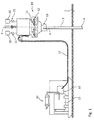
- FIG. 1 the structure of a vibration ram assembly according to the invention can be seen.
- the vibration ram arrangement has a hydraulic unit 14 and a vibration device 10, which is connected by means of hydraulic hoses 17 to a hydraulic pump 16 of the hydraulic unit 14.
- the hydraulic power unit 14 further includes an engine 15 configured to drive the hydraulic pump 16.
- axial vibrations are introduced into a trained as a profile 1 Rammgut 1, wherein the Rammgut 1 is connected by means of a clamping device 13 with the vibration device 10.
- the vibration device 10 together with the ramming material 1 fastened to it, is fastened to a crane 6, so that a weight force acting on a profile foot 3 of the pile material 1 can be influenced by a corresponding support via the crane 6.
- the vibration device 10 is hydraulically driven.
- the present invention is not limited to a hydraulic driving of the vibration device 10, because the unbalances 12 of the vibration assembly 10 can also be driven electrically.
- the drive of the imbalance 12 is so far no limitation.
- vibrating device 10 is clamped to a pile head 4 of the pile 1 by means of the clamping device 13, that is non-positively attached thereto and includes a drive in the form of the hydraulic motor 11 and a spring-mass system in the form of imbalances 12, about which the profile 1 or the profile head 4 is placed in a vertically oscillating movement, so that propagates in the profile 1, a standing wave. Part of this so entering the profile 1 vibration energy is consumed by the skin friction of penetrating into the ground 2 profile 1. Part of the vibration energy, the vibration energy arriving at the profile foot 3 is required to overcome the tip resistance of the profile 1 when penetrating into the ground 2, which ultimately causes the penetration of the profile 1 in the ground 2.
- the vibrations introduced via the vibration device 10 propagate through the profile 1 from the profile head 4 over the length of the profile 1 to the profile foot 3 and into the ground 2, so that the ground 2 liquefies below or in front of the profile foot 3 and the skin friction of the clamping length of the registered in the ground profile 1 is overcome, so that the profile 1 by virtue of its weight penetrates into the ground 2, when the load is adjusted to the crane 6 accordingly.
- a mass of the vibration device 10 and / or of the pile material 1 is varied during the introduction or penetration of the pile material into the ground.
- the vibration arrangement in the illustrated embodiment has two additional weights 20, which are elastically attached to the vibration device 10. The connection between the additional weights 20 and the vibration device thus takes place via a spring connection 21.
- the additional weight 20 or the additional weights 20 is rigidly connected to the vibration device 10 is / are.
- the additional weights 20 Due to the elastic attachment of the additional weights 20 to the vibration device 10 was carried out with activated vibration device 10, a vibration excitation of the additional weights 20, so that the vibration device 10 itself acts in addition to its excitation function as a kind of high-frequency hammer. Because the additional weights 20 oscillate with a hover frequency with respect to the vibration device 10, wherein the hover frequency by the exciting frequency, which is determined by the rotational speed of the imbalance 12, by the mass of the additional weights 20 and by the spring connections 21 induced spring force between the additional weights 20 and Vibration device 10, results.
- the oscillation frequency of the vibration device 10 is further provided to vary the oscillation frequency of the vibration device 10 as an excitation frequency over the insertion length to the final depth of the profile 2 and, if appropriate, beyond that in a post-compression phase.
- the vibration frequency of the vibration device 10 can be varied in a frequency range between 5 Hz to 150 Hz, preferably between 10 Hz to 50 Hz during the vibration process within a given liquefaction frequency band of the ground 2, so that, for example, a targeted change in the penetration rate of the profile 1 by the frequency change can be achieved within this frequency band in the range between 5 Hz and 150 Hz.
- a change in the penetration rate of the profile 1 can alternatively be achieved in that the frequency within the frequency band between 5 and 150 Hz, preferably between 10 Hz and 50 Hz is chosen so that the lowest possible penetration of the profile 1 is achieved so that the profile 1 just just by virtue of its weight and the weight of the attached vibration device 10 in the Subsoil 2 penetrates.
Landscapes
- Engineering & Computer Science (AREA)
- Life Sciences & Earth Sciences (AREA)
- General Life Sciences & Earth Sciences (AREA)
- Mining & Mineral Resources (AREA)
- Paleontology (AREA)
- Civil Engineering (AREA)
- General Engineering & Computer Science (AREA)
- Structural Engineering (AREA)
- Placing Or Removing Of Piles Or Sheet Piles, Or Accessories Thereof (AREA)
Priority Applications (1)
| Application Number | Priority Date | Filing Date | Title |
|---|---|---|---|
| PL16152736T PL3051027T3 (pl) | 2015-01-29 | 2016-01-26 | Sposób wbijania wibracyjnego oraz układ do wbijania wibracyjnego |
Applications Claiming Priority (1)
| Application Number | Priority Date | Filing Date | Title |
|---|---|---|---|
| DE102015201502.5A DE102015201502A1 (de) | 2015-01-29 | 2015-01-29 | Verfahren zum Vibrationsrammen und Vibrationsrammanordnung |
Publications (2)
| Publication Number | Publication Date |
|---|---|
| EP3051027A1 true EP3051027A1 (fr) | 2016-08-03 |
| EP3051027B1 EP3051027B1 (fr) | 2017-11-29 |
Family
ID=55236278
Family Applications (1)
| Application Number | Title | Priority Date | Filing Date |
|---|---|---|---|
| EP16152736.1A Active EP3051027B1 (fr) | 2015-01-29 | 2016-01-26 | Procede de mise en place par vibrations et systeme de placer par vibrations |
Country Status (5)
| Country | Link |
|---|---|
| EP (1) | EP3051027B1 (fr) |
| DE (1) | DE102015201502A1 (fr) |
| DK (1) | DK3051027T3 (fr) |
| NO (1) | NO2737270T3 (fr) |
| PL (1) | PL3051027T3 (fr) |
Citations (1)
| Publication number | Priority date | Publication date | Assignee | Title |
|---|---|---|---|---|
| DE1191755B (de) * | 1956-06-27 | 1965-04-22 | Carl Schenk Maschinenfabrik G | Vorrichtung zum Eintreiben von Pfaehlen, Rohren, Spundbohlen od. dgl. mit einem Schwingungs-erzeuger |
-
2012
- 2012-06-29 NO NO12817291A patent/NO2737270T3/no unknown
-
2015
- 2015-01-29 DE DE102015201502.5A patent/DE102015201502A1/de not_active Withdrawn
-
2016
- 2016-01-26 EP EP16152736.1A patent/EP3051027B1/fr active Active
- 2016-01-26 PL PL16152736T patent/PL3051027T3/pl unknown
- 2016-01-26 DK DK16152736.1T patent/DK3051027T3/en active
Patent Citations (1)
| Publication number | Priority date | Publication date | Assignee | Title |
|---|---|---|---|---|
| DE1191755B (de) * | 1956-06-27 | 1965-04-22 | Carl Schenk Maschinenfabrik G | Vorrichtung zum Eintreiben von Pfaehlen, Rohren, Spundbohlen od. dgl. mit einem Schwingungs-erzeuger |
Also Published As
| Publication number | Publication date |
|---|---|
| PL3051027T3 (pl) | 2018-05-30 |
| EP3051027B1 (fr) | 2017-11-29 |
| NO2737270T3 (fr) | 2018-09-01 |
| DK3051027T3 (en) | 2018-03-05 |
| DE102015201502A1 (de) | 2016-08-04 |
Similar Documents
| Publication | Publication Date | Title |
|---|---|---|
| EP3927899B1 (fr) | Introduction par vibration de fondations | |
| DE1634732A1 (de) | Gesteinsmeissel zum Ebnen oder Aufreissen von Felsboden | |
| WO2014095767A1 (fr) | Dispositif et procédé de compactage du sol et/ou de stabilisation du sol | |
| DE102019124415A1 (de) | Unwuchtsystem mit reduzierter rotationsträgheit für vibrationsverdichter | |
| WO2020207651A1 (fr) | Revêtement pour fondation | |
| DE1634506A1 (de) | Verfahren zum Eintreiben oder Herausloesen von Traegern in den bzw.aus dem Boden | |
| EP2884006B1 (fr) | Pieux et procédé de pose d'un pieu battu au fond de la mer | |
| EP3051027B1 (fr) | Procede de mise en place par vibrations et systeme de placer par vibrations | |
| DE934220C (de) | Verfahren und Vorrichtung zum Eintreiben oder Ziehen von Pfaehlen, Bohlen, Rohren u. dgl. | |
| EP4335974B1 (fr) | Procédé d'application d'un profilé dans le souterrain, ainsi que dispositif vibrateur associé | |
| EP3109365B1 (fr) | Procede de commande d'un marteau a vibration | |
| EP3051028B1 (fr) | Procede de battage par vibration | |
| EP0151389B1 (fr) | Méthode et dispositif pour la réalisation d'éléments de construction dans le sol tels que pieux, ancrages injectés, murs souterrains ou similaires | |
| DE102014016400B4 (de) | Vibrationsrammanordnung mit integriertem Antriebsaggregat | |
| DE4026111C2 (fr) | ||
| EP3684981A1 (fr) | Procédé d'installation d'un pieu et pieu | |
| DE19740800B4 (de) | Verfahren zum Einbringen von Bohlen in Erdreich | |
| AT214622B (de) | Verfahren und Vorrichtung zur Durchführung von Rüttelarbeiten durch Innenrüttlung | |
| DE2619431A1 (de) | Verfahren zum herstellen eines ortbetonpfahles | |
| DE3400741C2 (fr) | ||
| DE102011111036A1 (de) | Verfahren und Vorrichtung zum Einbringen eines Gründungsrohres in den Meeresboden, insbesondere für die Gründung einer Offshore-Windenergieanlage | |
| JP2575032B2 (ja) | 砂質地盤振動固め工法 | |
| EP3542000A1 (fr) | Procédé de démantèlement de structures de fondation en mer | |
| DE2654994A1 (de) | Rammverfahren und einrichtung zu dessen ausfuehrung | |
| DE902120C (de) | Vorrichtung zur Herstellung von Ortpfaehlen |
Legal Events
| Date | Code | Title | Description |
|---|---|---|---|
| PUAI | Public reference made under article 153(3) epc to a published international application that has entered the european phase |
Free format text: ORIGINAL CODE: 0009012 |
|
| AK | Designated contracting states |
Kind code of ref document: A1 Designated state(s): AL AT BE BG CH CY CZ DE DK EE ES FI FR GB GR HR HU IE IS IT LI LT LU LV MC MK MT NL NO PL PT RO RS SE SI SK SM TR |
|
| AX | Request for extension of the european patent |
Extension state: BA ME |
|
| 17P | Request for examination filed |
Effective date: 20170202 |
|
| RBV | Designated contracting states (corrected) |
Designated state(s): AL AT BE BG CH CY CZ DE DK EE ES FI FR GB GR HR HU IE IS IT LI LT LU LV MC MK MT NL NO PL PT RO RS SE SI SK SM TR |
|
| RAP1 | Party data changed (applicant data changed or rights of an application transferred) |
Owner name: INNOGY SE |
|
| GRAP | Despatch of communication of intention to grant a patent |
Free format text: ORIGINAL CODE: EPIDOSNIGR1 |
|
| INTG | Intention to grant announced |
Effective date: 20170808 |
|
| GRAS | Grant fee paid |
Free format text: ORIGINAL CODE: EPIDOSNIGR3 |
|
| GRAA | (expected) grant |
Free format text: ORIGINAL CODE: 0009210 |
|
| AK | Designated contracting states |
Kind code of ref document: B1 Designated state(s): AL AT BE BG CH CY CZ DE DK EE ES FI FR GB GR HR HU IE IS IT LI LT LU LV MC MK MT NL NO PL PT RO RS SE SI SK SM TR |
|
| REG | Reference to a national code |
Ref country code: CH Ref legal event code: EP |
|
| REG | Reference to a national code |
Ref country code: AT Ref legal event code: REF Ref document number: 950523 Country of ref document: AT Kind code of ref document: T Effective date: 20171215 |
|
| REG | Reference to a national code |
Ref country code: IE Ref legal event code: FG4D Free format text: LANGUAGE OF EP DOCUMENT: GERMAN |
|
| REG | Reference to a national code |
Ref country code: DE Ref legal event code: R096 Ref document number: 502016000302 Country of ref document: DE |
|
| REG | Reference to a national code |
Ref country code: FR Ref legal event code: PLFP Year of fee payment: 3 |
|
| REG | Reference to a national code |
Ref country code: DK Ref legal event code: T3 Effective date: 20180302 |
|
| REG | Reference to a national code |
Ref country code: NL Ref legal event code: FP |
|
| REG | Reference to a national code |
Ref country code: SE Ref legal event code: TRGR |
|
| REG | Reference to a national code |
Ref country code: LT Ref legal event code: MG4D |
|
| PG25 | Lapsed in a contracting state [announced via postgrant information from national office to epo] |
Ref country code: LT Free format text: LAPSE BECAUSE OF FAILURE TO SUBMIT A TRANSLATION OF THE DESCRIPTION OR TO PAY THE FEE WITHIN THE PRESCRIBED TIME-LIMIT Effective date: 20171129 Ref country code: ES Free format text: LAPSE BECAUSE OF FAILURE TO SUBMIT A TRANSLATION OF THE DESCRIPTION OR TO PAY THE FEE WITHIN THE PRESCRIBED TIME-LIMIT Effective date: 20171129 Ref country code: FI Free format text: LAPSE BECAUSE OF FAILURE TO SUBMIT A TRANSLATION OF THE DESCRIPTION OR TO PAY THE FEE WITHIN THE PRESCRIBED TIME-LIMIT Effective date: 20171129 |
|
| REG | Reference to a national code |
Ref country code: NO Ref legal event code: T2 Effective date: 20171129 |
|
| PG25 | Lapsed in a contracting state [announced via postgrant information from national office to epo] |
Ref country code: HR Free format text: LAPSE BECAUSE OF FAILURE TO SUBMIT A TRANSLATION OF THE DESCRIPTION OR TO PAY THE FEE WITHIN THE PRESCRIBED TIME-LIMIT Effective date: 20171129 Ref country code: RS Free format text: LAPSE BECAUSE OF FAILURE TO SUBMIT A TRANSLATION OF THE DESCRIPTION OR TO PAY THE FEE WITHIN THE PRESCRIBED TIME-LIMIT Effective date: 20171129 Ref country code: GR Free format text: LAPSE BECAUSE OF FAILURE TO SUBMIT A TRANSLATION OF THE DESCRIPTION OR TO PAY THE FEE WITHIN THE PRESCRIBED TIME-LIMIT Effective date: 20180301 Ref country code: LV Free format text: LAPSE BECAUSE OF FAILURE TO SUBMIT A TRANSLATION OF THE DESCRIPTION OR TO PAY THE FEE WITHIN THE PRESCRIBED TIME-LIMIT Effective date: 20171129 Ref country code: BG Free format text: LAPSE BECAUSE OF FAILURE TO SUBMIT A TRANSLATION OF THE DESCRIPTION OR TO PAY THE FEE WITHIN THE PRESCRIBED TIME-LIMIT Effective date: 20180228 |
|
| PG25 | Lapsed in a contracting state [announced via postgrant information from national office to epo] |
Ref country code: SK Free format text: LAPSE BECAUSE OF FAILURE TO SUBMIT A TRANSLATION OF THE DESCRIPTION OR TO PAY THE FEE WITHIN THE PRESCRIBED TIME-LIMIT Effective date: 20171129 Ref country code: CZ Free format text: LAPSE BECAUSE OF FAILURE TO SUBMIT A TRANSLATION OF THE DESCRIPTION OR TO PAY THE FEE WITHIN THE PRESCRIBED TIME-LIMIT Effective date: 20171129 Ref country code: CY Free format text: LAPSE BECAUSE OF FAILURE TO SUBMIT A TRANSLATION OF THE DESCRIPTION OR TO PAY THE FEE WITHIN THE PRESCRIBED TIME-LIMIT Effective date: 20171129 Ref country code: EE Free format text: LAPSE BECAUSE OF FAILURE TO SUBMIT A TRANSLATION OF THE DESCRIPTION OR TO PAY THE FEE WITHIN THE PRESCRIBED TIME-LIMIT Effective date: 20171129 |
|
| REG | Reference to a national code |
Ref country code: DE Ref legal event code: R097 Ref document number: 502016000302 Country of ref document: DE |
|
| PG25 | Lapsed in a contracting state [announced via postgrant information from national office to epo] |
Ref country code: RO Free format text: LAPSE BECAUSE OF FAILURE TO SUBMIT A TRANSLATION OF THE DESCRIPTION OR TO PAY THE FEE WITHIN THE PRESCRIBED TIME-LIMIT Effective date: 20171129 Ref country code: SM Free format text: LAPSE BECAUSE OF FAILURE TO SUBMIT A TRANSLATION OF THE DESCRIPTION OR TO PAY THE FEE WITHIN THE PRESCRIBED TIME-LIMIT Effective date: 20171129 |
|
| PG25 | Lapsed in a contracting state [announced via postgrant information from national office to epo] |
Ref country code: MT Free format text: LAPSE BECAUSE OF FAILURE TO SUBMIT A TRANSLATION OF THE DESCRIPTION OR TO PAY THE FEE WITHIN THE PRESCRIBED TIME-LIMIT Effective date: 20171129 |
|
| PLBE | No opposition filed within time limit |
Free format text: ORIGINAL CODE: 0009261 |
|
| STAA | Information on the status of an ep patent application or granted ep patent |
Free format text: STATUS: NO OPPOSITION FILED WITHIN TIME LIMIT |
|
| PG25 | Lapsed in a contracting state [announced via postgrant information from national office to epo] |
Ref country code: LU Free format text: LAPSE BECAUSE OF NON-PAYMENT OF DUE FEES Effective date: 20180126 |
|
| 26N | No opposition filed |
Effective date: 20180830 |
|
| PG25 | Lapsed in a contracting state [announced via postgrant information from national office to epo] |
Ref country code: SI Free format text: LAPSE BECAUSE OF FAILURE TO SUBMIT A TRANSLATION OF THE DESCRIPTION OR TO PAY THE FEE WITHIN THE PRESCRIBED TIME-LIMIT Effective date: 20171129 |
|
| PG25 | Lapsed in a contracting state [announced via postgrant information from national office to epo] |
Ref country code: MC Free format text: LAPSE BECAUSE OF FAILURE TO SUBMIT A TRANSLATION OF THE DESCRIPTION OR TO PAY THE FEE WITHIN THE PRESCRIBED TIME-LIMIT Effective date: 20171129 |
|
| REG | Reference to a national code |
Ref country code: CH Ref legal event code: PL |
|
| PG25 | Lapsed in a contracting state [announced via postgrant information from national office to epo] |
Ref country code: LI Free format text: LAPSE BECAUSE OF NON-PAYMENT OF DUE FEES Effective date: 20190131 Ref country code: CH Free format text: LAPSE BECAUSE OF NON-PAYMENT OF DUE FEES Effective date: 20190131 |
|
| PG25 | Lapsed in a contracting state [announced via postgrant information from national office to epo] |
Ref country code: TR Free format text: LAPSE BECAUSE OF FAILURE TO SUBMIT A TRANSLATION OF THE DESCRIPTION OR TO PAY THE FEE WITHIN THE PRESCRIBED TIME-LIMIT Effective date: 20171129 |
|
| PG25 | Lapsed in a contracting state [announced via postgrant information from national office to epo] |
Ref country code: PT Free format text: LAPSE BECAUSE OF FAILURE TO SUBMIT A TRANSLATION OF THE DESCRIPTION OR TO PAY THE FEE WITHIN THE PRESCRIBED TIME-LIMIT Effective date: 20171129 |
|
| PG25 | Lapsed in a contracting state [announced via postgrant information from national office to epo] |
Ref country code: HU Free format text: LAPSE BECAUSE OF FAILURE TO SUBMIT A TRANSLATION OF THE DESCRIPTION OR TO PAY THE FEE WITHIN THE PRESCRIBED TIME-LIMIT; INVALID AB INITIO Effective date: 20160126 Ref country code: MK Free format text: LAPSE BECAUSE OF NON-PAYMENT OF DUE FEES Effective date: 20171129 |
|
| PG25 | Lapsed in a contracting state [announced via postgrant information from national office to epo] |
Ref country code: AL Free format text: LAPSE BECAUSE OF FAILURE TO SUBMIT A TRANSLATION OF THE DESCRIPTION OR TO PAY THE FEE WITHIN THE PRESCRIBED TIME-LIMIT Effective date: 20171129 Ref country code: IS Free format text: LAPSE BECAUSE OF FAILURE TO SUBMIT A TRANSLATION OF THE DESCRIPTION OR TO PAY THE FEE WITHIN THE PRESCRIBED TIME-LIMIT Effective date: 20180329 |
|
| REG | Reference to a national code |
Ref country code: DE Ref legal event code: R081 Ref document number: 502016000302 Country of ref document: DE Owner name: RWE OFFSHORE WIND GMBH, DE Free format text: FORMER OWNER: INNOGY SE, 45128 ESSEN, DE Ref country code: DE Ref legal event code: R081 Ref document number: 502016000302 Country of ref document: DE Owner name: RWE RENEWABLES GMBH, DE Free format text: FORMER OWNER: INNOGY SE, 45128 ESSEN, DE |
|
| REG | Reference to a national code |
Ref country code: AT Ref legal event code: MM01 Ref document number: 950523 Country of ref document: AT Kind code of ref document: T Effective date: 20210126 |
|
| PG25 | Lapsed in a contracting state [announced via postgrant information from national office to epo] |
Ref country code: AT Free format text: LAPSE BECAUSE OF NON-PAYMENT OF DUE FEES Effective date: 20210126 |
|
| REG | Reference to a national code |
Ref country code: DE Ref legal event code: R081 Ref document number: 502016000302 Country of ref document: DE Owner name: RWE OFFSHORE WIND GMBH, DE Free format text: FORMER OWNER: RWE RENEWABLES GMBH, 45145 ESSEN, DE |
|
| P01 | Opt-out of the competence of the unified patent court (upc) registered |
Effective date: 20230530 |
|
| PGFP | Annual fee paid to national office [announced via postgrant information from national office to epo] |
Ref country code: NL Payment date: 20260121 Year of fee payment: 11 |
|
| PGFP | Annual fee paid to national office [announced via postgrant information from national office to epo] |
Ref country code: SE Payment date: 20260121 Year of fee payment: 11 |
|
| PGFP | Annual fee paid to national office [announced via postgrant information from national office to epo] |
Ref country code: GB Payment date: 20260122 Year of fee payment: 11 |
|
| PGFP | Annual fee paid to national office [announced via postgrant information from national office to epo] |
Ref country code: NO Payment date: 20260120 Year of fee payment: 11 Ref country code: DK Payment date: 20260121 Year of fee payment: 11 Ref country code: DE Payment date: 20260120 Year of fee payment: 11 Ref country code: IE Payment date: 20260121 Year of fee payment: 11 |
|
| PGFP | Annual fee paid to national office [announced via postgrant information from national office to epo] |
Ref country code: IT Payment date: 20260130 Year of fee payment: 11 Ref country code: BE Payment date: 20260121 Year of fee payment: 11 |
|
| PGFP | Annual fee paid to national office [announced via postgrant information from national office to epo] |
Ref country code: FR Payment date: 20260127 Year of fee payment: 11 |
|
| PGFP | Annual fee paid to national office [announced via postgrant information from national office to epo] |
Ref country code: PL Payment date: 20260113 Year of fee payment: 11 |