EP3051099B1 - Compresseur à géometrie d'écoulement variable - Google Patents
Compresseur à géometrie d'écoulement variable Download PDFInfo
- Publication number
- EP3051099B1 EP3051099B1 EP15199551.1A EP15199551A EP3051099B1 EP 3051099 B1 EP3051099 B1 EP 3051099B1 EP 15199551 A EP15199551 A EP 15199551A EP 3051099 B1 EP3051099 B1 EP 3051099B1
- Authority
- EP
- European Patent Office
- Prior art keywords
- aperture
- compressor
- exhaust
- flow
- compressor arrangement
- Prior art date
- Legal status (The legal status is an assumption and is not a legal conclusion. Google has not performed a legal analysis and makes no representation as to the accuracy of the status listed.)
- Not-in-force
Links
Images

Classifications
-
- F—MECHANICAL ENGINEERING; LIGHTING; HEATING; WEAPONS; BLASTING
- F02—COMBUSTION ENGINES; HOT-GAS OR COMBUSTION-PRODUCT ENGINE PLANTS
- F02B—INTERNAL-COMBUSTION PISTON ENGINES; COMBUSTION ENGINES IN GENERAL
- F02B37/00—Engines characterised by provision of pumps driven at least for part of the time by exhaust
- F02B37/12—Control of the pumps
- F02B37/22—Control of the pumps by varying cross-section of exhaust passages or air passages, e.g. by throttling turbine inlets or outlets or by varying effective number of guide conduits
- F02B37/225—Control of the pumps by varying cross-section of exhaust passages or air passages, e.g. by throttling turbine inlets or outlets or by varying effective number of guide conduits air passages
-
- F—MECHANICAL ENGINEERING; LIGHTING; HEATING; WEAPONS; BLASTING
- F01—MACHINES OR ENGINES IN GENERAL; ENGINE PLANTS IN GENERAL; STEAM ENGINES
- F01D—NON-POSITIVE DISPLACEMENT MACHINES OR ENGINES, e.g. STEAM TURBINES
- F01D17/00—Regulating or controlling by varying flow
- F01D17/10—Final actuators
- F01D17/12—Final actuators arranged in stator parts
- F01D17/14—Final actuators arranged in stator parts varying effective cross-sectional area of nozzles or guide conduits
-
- F—MECHANICAL ENGINEERING; LIGHTING; HEATING; WEAPONS; BLASTING
- F01—MACHINES OR ENGINES IN GENERAL; ENGINE PLANTS IN GENERAL; STEAM ENGINES
- F01D—NON-POSITIVE DISPLACEMENT MACHINES OR ENGINES, e.g. STEAM TURBINES
- F01D17/00—Regulating or controlling by varying flow
- F01D17/10—Final actuators
- F01D17/12—Final actuators arranged in stator parts
- F01D17/14—Final actuators arranged in stator parts varying effective cross-sectional area of nozzles or guide conduits
- F01D17/141—Final actuators arranged in stator parts varying effective cross-sectional area of nozzles or guide conduits by means of shiftable members or valves obturating part of the flow path
-
- F—MECHANICAL ENGINEERING; LIGHTING; HEATING; WEAPONS; BLASTING
- F02—COMBUSTION ENGINES; HOT-GAS OR COMBUSTION-PRODUCT ENGINE PLANTS
- F02M—SUPPLYING COMBUSTION ENGINES IN GENERAL WITH COMBUSTIBLE MIXTURES OR CONSTITUENTS THEREOF
- F02M26/00—Engine-pertinent apparatus for adding exhaust gases to combustion-air, main fuel or fuel-air mixture, e.g. by exhaust gas recirculation [EGR] systems
- F02M26/02—EGR systems specially adapted for supercharged engines
- F02M26/04—EGR systems specially adapted for supercharged engines with a single turbocharger
- F02M26/06—Low pressure loops, i.e. wherein recirculated exhaust gas is taken out from the exhaust downstream of the turbocharger turbine and reintroduced into the intake system upstream of the compressor
-
- F—MECHANICAL ENGINEERING; LIGHTING; HEATING; WEAPONS; BLASTING
- F02—COMBUSTION ENGINES; HOT-GAS OR COMBUSTION-PRODUCT ENGINE PLANTS
- F02M—SUPPLYING COMBUSTION ENGINES IN GENERAL WITH COMBUSTIBLE MIXTURES OR CONSTITUENTS THEREOF
- F02M26/00—Engine-pertinent apparatus for adding exhaust gases to combustion-air, main fuel or fuel-air mixture, e.g. by exhaust gas recirculation [EGR] systems
- F02M26/02—EGR systems specially adapted for supercharged engines
- F02M26/09—Constructional details, e.g. structural combinations of EGR systems and supercharger systems; Arrangement of the EGR and supercharger systems with respect to the engine
-
- F—MECHANICAL ENGINEERING; LIGHTING; HEATING; WEAPONS; BLASTING
- F04—POSITIVE - DISPLACEMENT MACHINES FOR LIQUIDS; PUMPS FOR LIQUIDS OR ELASTIC FLUIDS
- F04D—NON-POSITIVE-DISPLACEMENT PUMPS
- F04D27/00—Control, e.g. regulation, of pumps, pumping installations or pumping systems specially adapted for elastic fluids
- F04D27/02—Surge control
- F04D27/0253—Surge control by throttling
-
- F—MECHANICAL ENGINEERING; LIGHTING; HEATING; WEAPONS; BLASTING
- F04—POSITIVE - DISPLACEMENT MACHINES FOR LIQUIDS; PUMPS FOR LIQUIDS OR ELASTIC FLUIDS
- F04D—NON-POSITIVE-DISPLACEMENT PUMPS
- F04D29/00—Details, component parts, or accessories
- F04D29/40—Casings; Connections of working fluid
- F04D29/42—Casings; Connections of working fluid for radial or helico-centrifugal pumps
- F04D29/4206—Casings; Connections of working fluid for radial or helico-centrifugal pumps especially adapted for elastic fluid pumps
- F04D29/4213—Casings; Connections of working fluid for radial or helico-centrifugal pumps especially adapted for elastic fluid pumps suction ports
-
- F—MECHANICAL ENGINEERING; LIGHTING; HEATING; WEAPONS; BLASTING
- F04—POSITIVE - DISPLACEMENT MACHINES FOR LIQUIDS; PUMPS FOR LIQUIDS OR ELASTIC FLUIDS
- F04D—NON-POSITIVE-DISPLACEMENT PUMPS
- F04D29/00—Details, component parts, or accessories
- F04D29/40—Casings; Connections of working fluid
- F04D29/42—Casings; Connections of working fluid for radial or helico-centrifugal pumps
- F04D29/44—Fluid-guiding means, e.g. diffusers
- F04D29/46—Fluid-guiding means, e.g. diffusers adjustable
- F04D29/462—Fluid-guiding means, e.g. diffusers adjustable especially adapted for elastic fluid pumps
- F04D29/464—Fluid-guiding means, e.g. diffusers adjustable especially adapted for elastic fluid pumps adjusting flow cross-section, otherwise than by using adjustable stator blades
-
- F—MECHANICAL ENGINEERING; LIGHTING; HEATING; WEAPONS; BLASTING
- F02—COMBUSTION ENGINES; HOT-GAS OR COMBUSTION-PRODUCT ENGINE PLANTS
- F02B—INTERNAL-COMBUSTION PISTON ENGINES; COMBUSTION ENGINES IN GENERAL
- F02B37/00—Engines characterised by provision of pumps driven at least for part of the time by exhaust
- F02B37/04—Engines with exhaust drive and other drive of pumps, e.g. with exhaust-driven pump and mechanically-driven second pump
- F02B37/10—Engines with exhaust drive and other drive of pumps, e.g. with exhaust-driven pump and mechanically-driven second pump at least one pump being alternatively or simultaneously driven by exhaust and other drive, e.g. by pressurised fluid from a reservoir or an engine-driven pump
-
- F—MECHANICAL ENGINEERING; LIGHTING; HEATING; WEAPONS; BLASTING
- F02—COMBUSTION ENGINES; HOT-GAS OR COMBUSTION-PRODUCT ENGINE PLANTS
- F02B—INTERNAL-COMBUSTION PISTON ENGINES; COMBUSTION ENGINES IN GENERAL
- F02B39/00—Component parts, details, or accessories relating to, driven charging or scavenging pumps, not provided for in groups F02B33/00 - F02B37/00
- F02B39/02—Drives of pumps; Varying pump drive gear ratio
- F02B39/08—Non-mechanical drives, e.g. fluid drives having variable gear ratio
- F02B39/10—Non-mechanical drives, e.g. fluid drives having variable gear ratio electric
-
- F—MECHANICAL ENGINEERING; LIGHTING; HEATING; WEAPONS; BLASTING
- F05—INDEXING SCHEMES RELATING TO ENGINES OR PUMPS IN VARIOUS SUBCLASSES OF CLASSES F01-F04
- F05D—INDEXING SCHEME FOR ASPECTS RELATING TO NON-POSITIVE-DISPLACEMENT MACHINES OR ENGINES, GAS-TURBINES OR JET-PROPULSION PLANTS
- F05D2220/00—Application
- F05D2220/40—Application in turbochargers
-
- F—MECHANICAL ENGINEERING; LIGHTING; HEATING; WEAPONS; BLASTING
- F05—INDEXING SCHEMES RELATING TO ENGINES OR PUMPS IN VARIOUS SUBCLASSES OF CLASSES F01-F04
- F05D—INDEXING SCHEME FOR ASPECTS RELATING TO NON-POSITIVE-DISPLACEMENT MACHINES OR ENGINES, GAS-TURBINES OR JET-PROPULSION PLANTS
- F05D2250/00—Geometry
- F05D2250/50—Inlet or outlet
- F05D2250/51—Inlet
-
- Y—GENERAL TAGGING OF NEW TECHNOLOGICAL DEVELOPMENTS; GENERAL TAGGING OF CROSS-SECTIONAL TECHNOLOGIES SPANNING OVER SEVERAL SECTIONS OF THE IPC; TECHNICAL SUBJECTS COVERED BY FORMER USPC CROSS-REFERENCE ART COLLECTIONS [XRACs] AND DIGESTS
- Y02—TECHNOLOGIES OR APPLICATIONS FOR MITIGATION OR ADAPTATION AGAINST CLIMATE CHANGE
- Y02T—CLIMATE CHANGE MITIGATION TECHNOLOGIES RELATED TO TRANSPORTATION
- Y02T10/00—Road transport of goods or passengers
- Y02T10/10—Internal combustion engine [ICE] based vehicles
- Y02T10/12—Improving ICE efficiencies
Definitions
- the invention relates to a compressor arrangement having a compressor impeller, an inflow channel arranged upstream of the compressor impeller, and an adjusting device for changing a flow cross section of the inflow channel upstream of the compressor impeller, such as a trim plate, according to the preamble of claim 1.
- a compressor arrangement is part of an exhaust gas turbocharger for an internal combustion engine used.
- exhaust gas turbochargers are used in internal combustion engines, such as diesel and gasoline engines. With a compressor of the exhaust gas turbocharger, the fresh gas supplied via the fresh gas train of the internal combustion engine is compressed. In order to improve the variability and the response behavior of turbochargers, variable turbine geometries (VTG) are regularly used. A variable compressor geometry increases the variability of the charging system as another technology.
- turbocharger With the increasing charging level of modern internal combustion engines, the demands on the operating range (maps) of the turbocharger also increase.
- the background to this are the requirements of the internal combustion engine to achieve the maximum torque even at the lowest possible engine speeds, while at the same time constantly increasing the rated output.
- the turbocharger must ensure high charge pressures even at low air mass flows (range of the pumping limit) and at the same time enable the high air mass flow at rated power with the required boost pressures.
- conventional turbochargers quickly reach their limits with regard to the possible operating range spread (characteristic map width) of the compressor and turbine stages.
- a small compressor trim is necessary and for the representation of high engine power at nominal speed a large compressor trim. For this reason, it may be advantageous to provide a flow channel with trim variability.
- An adjustment device such as a trim plate serves to shift the surge limit of a compressor map in the direction of low mass flows at high pressure conditions.
- a trim control can increase the compressor efficiency in the area of the pumping limit.
- a trim plate comprises an adjusting device, by means of which the inflow cross-section, in which the impeller of the compressor is flown, or the flow cross-section of the inflow channel in front of the impeller can be changed.
- the compressor inflow can be focused more strongly on the impeller-near flow cross-section of the compressor impeller.
- less fluid flows into the low-pulse and lossy region of the backflow bubble, and the core flow in the region near the hub is accelerated and thereby additionally stabilized.
- the acceleration of the flow in the region near the hub of the compressor also results in a suction-side displacement of the compressor inlet, which can contribute to a further stabilization of the flow.
- the stabilization of the core flow leads to the desired shift of the surge limit of the compressor map to lower mass flows.
- a generic internal combustion engine is from the DE 10 2010 026 176 A1 known.
- the trim controller there comprises a cone, which in one embodiment consists of a plurality of lamellae.
- the lamellae are arranged in two layers, wherein the lamellae of each layer are spaced apart from one another and the two layers are offset in relation to each other in rotation so that the lamellae of one layer cover the distances between the lamellae of the respective other layer.
- the pamphlets DE 10 2011 121 996 B4 and DE 10 2013 003 418 A1 describe other possibilities for changing the flow cross section of the inflow channel just before the compressor impeller by means of a Trimstellers.
- trimvariable compressors include a rotary ring, which controls a cam contour arranged in a circle lamellae.
- these fins are a weak point in the fatigue strength under extreme conditions; Furthermore, the reliability and controllability of the slats in transient engine operation is questionable.
- the publication DE 10 2013 006 928 A1 discloses an exhaust gas turbocharger with a turbine arrangement with variable outlet cross-section.
- the DE 20 2014 102 773 U1 discloses a compressor having an inlet channel divided into a central inlet channel and a throttle channel surrounding the central inlet channel in a short section in front of a compressor impeller and in an adjoining section radially surrounding the compressor impeller by means of a double-walled tubular wall structure.
- a diaphragm-shaped adjusting device is provided, by means of which the quantity of fresh gas flowing via the throttle channel to the 240 can be set. This should prevent a "compressor throttling".
- a recirculation channel is further integrated, on the one hand has an obliquely radially oriented inlet opening, which is arranged in the region of the radial circumference of the compressor impeller, and a radially aligned outlet opening, which is arranged axially in front of the compressor impeller.
- the object of the present invention to provide a compressor arrangement with trim variability, which allows a particularly simple and reliable controllability of the flow cross section and a higher fatigue strength than the above-mentioned compressor arrangements of the prior art.
- the adjusting device of the compressor arrangement according to the invention has a diaphragm arranged in the inflow channel with a central diaphragm opening and at least one further diaphragm opening in the form of an at least partially closable diaphragm window.
- the central aperture is not necessarily closed and thus forms a of the fresh gas in the direction of the compressor impeller flowed through and always open trim channel, which allows a central flow of the compressor impeller.
- the at least one aperture window which is arranged radially further outward than the central aperture opening in the inflow channel, is preferably also completely closable, so that while maintaining a minimum inflow cross section through the central aperture opening, the flow cross section of the inflow channel can be closed or opened of the aperture window is enlarged or reduced.
- the compressor arrangement according to the invention is based on the operating principle of the constriction of the compressor inlet cross-section, whereby the flow inlet velocity is increased.
- the adjustment device according to the invention which has a diaphragm with at least two openings, namely the central trim opening forming the central aperture and the eccentrically arranged closable aperture window, particularly robust and thus stable against extreme loads.
- the diaphragm preferably comprises an inflow surface running transversely, in particular approximately perpendicularly to the flow direction in the inflow channel, in which the diaphragm windows are formed as openings. Aperture windows are adjustable by simple means and continuously, as needed, from the fully open position to the fully closed position, so that the compressor assembly according to the invention is particularly reliable controllable.
- the central aperture is preferably circular and the aperture windows each circulate essentially in the form of a circular ring segment.
- a round cross-section of the inflow channel and the compressor impeller is used in the best possible way.
- each connecting segments, such as webs may be arranged, which separate the individual aperture window from each other.
- a particularly advantageous arrangement of the aperture windows is characterized in that of the n (n> 1) aperture windows, two adjacent aperture windows in each case enclose an angle of approximately 360 ° / n and / or each aperture window is configured in the form of a circular ring segment with a segment angle of 360 ° / 2n.
- corresponding geometries of the adjacent diaphragm windows have an angular spacing of 360 ° / n relative to the center axis of the adjustment device.
- Corresponding geometries are, for example, the aperture window centers, the right aperture window frames or the left aperture window frames.
- a fast and reliable controllability of the inflow cross section by closing or opening the aperture window can be provided by opening, in particular by adjusting, in particular by turning, a movable closure member such as an annular disc against a stationary in the inflow passage aperture portion partially or completely closed or opened are.
- the rotatable closing part is applied upstream of the orifice on a substantially annular, flat inflow surface of the diaphragm, which has the aperture window, so that it is urged by the inflowing fresh gas in the direction of the inflow surface.
- the stability of the adjusting device is increased overall.
- the closing part is an adjacent to the fixed aperture portion, rotatable about the longitudinal axis of the inflow channel annular disc with a central aperture adapted to the central aperture and adapted to the aperture window, the central ring opening in each case partially circumferential annular windows, the analog shaped are like the aperture windows.
- the angular position of the annular disk is set up such that the diaphragm windows are substantially superposed with the identically shaped annular windows, so that all the diaphragm windows are completely open.
- the angular position of the annular disc is set up such that the aperture windows are covered by the webs between the ring windows. Any intermediate angle positions are advantageously possible.
- the aperture windows allow the compressor to maintain its stuffing limit at equally high flow rates, which are typically shifted toward smaller throughputs with a smaller trim. Through the use of this turntable thus a continuous trim variability of the compressor inlet is possible.
- the rotatable disc has the advantages of ease of implementation, easy controllability, small size and high resistance to contamination, icing, etc.
- a trim channel with a comparatively small flow cross-section is formed by the central aperture.
- the central aperture is formed in the form of a pipe section which opens toward a central section of the compressor impeller.
- the orifice downstream of the central orifice has a pipe section with a predetermined, restricted trim cross section, through which the fresh gas can optionally be conducted at high flow velocity in the direction of a central section of the compressor impeller. Due to the nozzle-shaped design of this flow channel in front of the compressor impeller caused by the located in the inflow passage components hardly pressure losses. In the closed state of the aperture window, the flow cross section is reduced to the cross section of the pipe section. This allows the flow rate to be increased and the effective peripheral speed to be lowered at low flow rates, thereby shifting the surge line toward lower mass flows.
- a pipe section annularly surrounding Zuschaltkanal is formed which can be flowed through by the at least one closable aperture window.
- the interior of the pipe section through the central aperture is flowed, while the pipe section coaxial circumferential Zuschaltkanal is flowed through by the closable aperture window and thus switched on as needed or can be taken out of the flow path.
- a further increase in the variability of the Trimstellers, which allows an improved adaptation to different operating ranges, is achieved in that in the wall of the Pipe section at least one, and preferably a plurality of passages, such as holes are formed, which allow gas to flow through the pipe wall of the pipe section.
- these passages in the wall of the tube section are closable and openable, wherein preferably a continuous adjustment between a fully opened position and a fully closed position is possible.
- the compressor assembly according to the invention on the one hand, the preferably closable aperture window and on the other also preferably closable flow passages in the wall of the pipe section, which separates the central trim channel of him annularly surrounding Zuschaltkanal.
- the closable and openable passages thus the flow cross-sectional area between the Zuschaltkanal and the central trim channel can be adjusted as needed.
- the passages do not necessarily extend perpendicularly through the wall of the pipe section, but can in flow-optimized manner obliquely with respect to the main flow direction of the central trim channel in the pipe section wall be introduced in order to avoid in this way turbulence of the air flowing from the inflow channel through the pipe section wall in the central trim channel air.
- the closable aperture window is preferably the at least one and are preferably all passages by adjusting, in particular by turning a movable cover with respect to the diaphragm fixed in the inflow channel partially or completely closed and opened.
- the open position passages of the cover member are aligned with the passages in the pipe section wall, so that a flow is possible, and in the closed position, the passages in the pipe section wall are covered by a closed wall of the cover and thus closed.
- the cover member may include a sleeve portion abutting the inner surface of the wall of the tubular portion and rotatable about the central trim channel and having an array of passages corresponding to the array of apertures in the tubular portion and rotatable into a position aligned therewith.
- the closure part is formed integrally with the cover part.
- the closing part provided for closing the apertures is rotatable together with the cover member integrally formed therewith for closing the passages in the pipe section.
- the closure member may be formed in the form of approximately perpendicular to the main flow direction in the inflow passage extending annular disk and / or the cover may be formed in the form of a protruding from the annular disc in the pipe section sleeve paragraph.
- a second operating position is at least one aperture window and are preferably all aperture windows open and at least one pipe passage and preferably all pipe outlets are closed.
- the compressor impeller can be flown over both via the central trim channel and through the open aperture window via the Zuschaltkanal.
- a high air flow rate through the compressor is possible due to the large flow cross-section in the inflow passage, which is desired in particular at high engine speeds or under full load.
- a stepless adjustment of the flow cross section is preferably possible.
- At least one aperture window and preferably all aperture windows are closed, and at least one tube passage and preferably all tube passages are open.
- the compressor impeller via the central trim channel and via an exhaust gas recirculation described below, in the Zuschaltkanal opens, due to the open passages flowable at high flow rate.
- Another operating position in which both the aperture windows and the passages are fully open, is not necessarily provided because such an operating position can potentially lead to turbulence and other flow problems of the gas flowing through the aperture windows and through the passages.
- LP-EGR low-pressure exhaust gas recirculation
- the exhaust gas taken downstream of a turbine of an exhaust-gas turbocharger is introduced via a feed in front of the compressor of the exhaust-gas turbocharger into the inflow channel of the fresh-air line and drawn in by it with the fresh gas.
- the introduction of the recirculated exhaust gas should be as close as possible in front of the compressor in order to avoid or keep unwanted condensate formation in the fresh gas.
- a control valve is usually integrated into the LP EGR introduction prior to compressor entry.
- the compressor arrangement according to the invention preferably has such exhaust gas recirculation (EGR), by means of which exhaust gas originating from the exhaust tract can be introduced into the inflow channel upstream of the compressor impeller.
- EGR exhaust gas recirculation
- Both the supply line of the EGR and the setting device or the trim plate should be arranged as close as possible before the impeller of the compressor, which results in a competing installation space situation. Therefore, the exhaust gas recirculation of the compressor assembly according to the invention preferably opens in the region of the adjusting device in the intake passage.
- the EGR admixture in the inflow duct is preferably set up variably.
- a control valve may be arranged in the exhaust gas recirculation supply line in order to be able to adjust the amount of exhaust gas to be supplied to the compressor.
- an adjustment of the EGR admixture in the inflow passage through the above-described and preferably continuously openable and closable passages in the pipe section is possible.
- a high EGR rate can be adjusted through the opening of the passages in the pipe duct, since with open pipe passages a large flow cross-section between the exhaust gas recirculation and the central trim channel or the compressor impeller is formed.
- the EGR rate in the compressor assembly according to the invention by means of the adjustment is adjustable, can be completely dispensed with the use of an exhaust valve when using the compressor assembly according to the invention, if necessary.
- the EGR rate can be increased in a simple manner by opening the passages in the wall of the pipe section, since the flow cross section between the exhaust gas recirculation opening into the connection channel and the trim channel centrally flowing to the compressor rotor can thereby be increased.
- the above-explained third operating position with closed diaphragm windows and open passages thus serves in particular to provide a high LP EGR rate in predetermined speed and load ranges.
- the adjustment device can be designed to reduce and / or increase a flow cross section between the exhaust gas recirculation and the central trim channel or the compressor impeller.
- the inventive combination of setting or Trimsteller and EGR introduction in the inflow of the fresh air line and the possible variable gas mixing thereby offer a particularly high variability and good controllability of the compressor inlet and the exhaust gas turbocharger as a whole.
- a combination with an e-booster is possible alternatively or additionally.
- the compressor arrangement according to the invention has an e-booster or is combined with an e-booster in the form of an electric booster compressor.
- the e-booster can build up boost pressure right from the start, even at low engine speeds, and provide torque.
- the e-booster may be provided for electrically driving a compressor impeller and having an e-motor for this purpose.
- the desired torque increase in the region of low engine speeds can also be achieved stationarily in the compressor arrangement according to the invention by shifting the pumping limit.
- the combined use of an e-booster in conjunction with a compressor arrangement according to the invention with trim plate thus enables a dynamic (independent of the exhaust gas enthalpy) and stationary torque increase of the internal combustion engine in the low-speed range.
- the starting behavior of the vehicle can be positively influenced or the achievable nominal power can be increased with a mono-turbocharged internal combustion engine with the same starting performance.
- a part-load optimized turbine is necessary.
- part-load optimized aerodynamic design of the turbine and / or corresponding control methods such as the above-described VTG, WG individually or in combination, for use.
- Alternative options for the Trimsteller under these boundary conditions eg Scavenging are more complex and associated with higher costs.
- a particularly streamlined design of the adjustment is possible in that a funnel-shaped taper of the inflow is provided downstream of the diaphragm and upstream of the compressor impeller.
- the smallest flow diameter of the taper substantially corresponds to the diameter of the pipe section or is slightly larger than this.
- the smallest flow diameter of the taper is located immediately downstream of the end of the pipe section facing the compressor wheel, so that the taper forms the downstream end of the connection channel.
- the aperture windows form the upstream end of the Zuschaltkanals and the taper the downstream end of the Zuschaltkanals.
- the flow path of the Zuschaltkanals - guided by the taper - extends radially inward, so that the fluid flowing through the Zuschaltkanal fluid is merged with the fluid flowing through the pipe section.
- This annular flow path of the connection channel which is supplied radially from the outside to the central flow path, leads to a particularly stable and eddy-free flow behavior in the direction of the compressor impeller.
- the present invention relates to an internal combustion engine having an internal combustion engine, an exhaust system, a fresh gas train and an exhaust gas turbocharger with a turbine integrated into the exhaust system and a compressor assembly according to the invention integrated in the fresh gas train.
- a (LP) exhaust gas recirculation can be arranged between the exhaust gas line and the fresh gas line and open in the region of the adjusting device upstream of the compressor impeller into the inflow channel.
- the exhaust gas recirculation opens in the central trim channel annular encircling Zuschaltkanal which can be flowed over the aperture window.
- the EGR rate is controllably or controllably established by means of the adjustment device.
- the adjusting device for changing the flow cross section between the exhaust gas recirculation or the Zuschaltkanal and the central trim channel can be established.
- An internal combustion engine according to the invention does not necessarily have an exhaust valve for setting an EGR rate.
- the internal combustion engine has an e-booster in the form of an additional electric compressor, which may be connected in parallel or in series with the compressor arrangement.
- the present invention relates to a method for operating an internal combustion engine according to the invention, in which an exhaust gas flow rate is set by an exhaust gas recirculation flowing into the fresh gas line upstream of the compressor impeller by means of the adjustment device of the compressor arrangement.
- the adjustment device By the adjustment device, a flow cross section between the exhaust gas recirculation and the compressor impeller can be adjusted.
- the exhaust gas flow rate is adjusted by adjusting, in particular by turning a arranged in the inflow passage cover.
- the cover part can be designed to close passages between a central trim channel and a connecting channel which circulates in an annular manner and into which the exhaust gas recirculation opens.
- the EGR rate is adjusted regularly by means of an exhaust flap in the exhaust tract.
- the EGR rate is preferably set at least in predetermined operating and speed ranges not by means of the exhaust valve, but especially by means of the adjustment device in the inflow channel of the Frischgas Thalls. Accordingly, eliminates the associated with the use of an exhaust flap higher fuel consumption due to the higher exhaust backpressure.
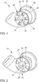
- FIG. 1 An embodiment of a compressor arrangement 10 without flow passages according to the invention is shown in FIG FIG. 1 shown in a perspective view. It is intended for installation in a fresh air line of an internal combustion engine with turbocharger.
- the exhaust gas turbocharger comprises a turbine arranged in the exhaust tract and driven by the exhaust gas (not shown) and driven by the turbine Centrifugal compressor with compressor impeller 50, which can be flowed through via a flow channel 20 with fresh gas.
- the compressor assembly 10 consists of the centrifugal compressor with compressor impeller 50 and from an upstream of the compressor impeller 50 arranged inflow passage 20 through which flows the compressor impeller 50 to be supplied fresh gas.
- the inflow passage 20 is connected directly downstream with the compressor downstream and may be formed in the form of an optionally modified suction hood.
- an adjusting device 30 for changing a flow cross-sectional area of the inflow passage 20 is arranged.
- the adjusting device 30 comprises a fixed aperture 32 in the inflow passage 32 with a centrally present in the inflow port aperture 34 and the central aperture 34 peripheral aperture windows 36.
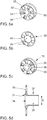
- the trim channel formed by the central aperture 34 and the pipe section 39 is not closable in the embodiment described here and thus provides a minimum flow cross-sectional area for low mass flows. This trim channel is particularly clear in Fig. 5d showing the aperture 32 in a cross-sectional view.
- the central orifice 34 has an inlet cross section 31, which gradually tapers in the direction of flow, in order to enable a low-loss flow course for the fresh gas entering the trim canal.
- the central aperture 34 is funnel-shaped, wherein the transition between the aperture 34 and pipe section 39 is rounded.
- Fig. 5a extending around the central aperture 34 around an annular substantially perpendicular to the flow direction extending aperture surface 35, in which the aperture window 36 are introduced.
- the aperture window 36 are formed substantially circular ring segment-like, so that the round cross section of the Anströmkanals 20 can be optimally utilized.
- each aperture window is shown, with two adjacent aperture windows each enclosing a mutual angle of approximately 60 ° and each aperture window extending through an angle of approximately 30 °. Between two diaphragm windows, the diaphragm surface 35 points each annular segment-shaped webs, which also each extend at an angle of about 30 °.
- a closure member 38 in the form of a rotatably mounted annular disc, wherein the annular disk as well as the aperture 32 has a central opening 44 and the central opening 44 ring-like circumferential annular window 46.
- the trained as an annular disc closure member 38 is particularly clear in Fig. 5b shown.
- the closure member 38 serves to close and to open the aperture window 36 by turning about the central flow axis.
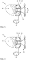
- the adjustment 30 in a fully open position in which all aperture windows 36 of fresh gas can be flowed through.
- the angular position of the aperture window 36 corresponds to that of the ring window 46.
- the pipe section 39 coaxially encircling inflow channel 25 can be flowed through the aperture window 36 with fresh gas.
- the flow path passing through the inflow channel 25 is converged radially inwardly with the central flow path through the tube section 39 by a taper 80 of the outer wall of the inflow channel 20.
- the course of these two flow paths is in Fig. 3 on the one hand by the two central arrows and on the other by the two outer arrows (inflow channel 25) indicated.
- the adjusting device 30 is in a closed position, in which only the central aperture 34 and thus the tube portion 39 of fresh gas can be flowed through.
- the trim is thereby reduced, whereby the flow rate can be raised.
- the aperture windows 36 are each offset from the annular windows 46, so that they are closed by the webs between the annular windows 46.
- a particularly important feature is the supply line of an exhaust gas recirculation 70 through which exhaust gas is introduced from the exhaust tract into the fresh gas branch upstream of the compressor impeller 50.
- the exhaust gas recirculation 70 opens in the region of the adjusting device 30, between the diaphragm surface 35 and the compressor impeller 50, in the inflow passage 20 a.
- the exhaust gas supplied through the exhaust gas recirculation 70 in the annular inflow channel 25 with the supplied through the aperture window 36 fresh gas can be mixed.
- different mixing ratios can be set.
- This includes the present invention is a variable EGR admixture. This combination of EGR introduction and mixing with the fresh gas while maintaining the minimum fresh gas flow diameter through the central orifice 34 is to be found to be particularly advantageous.
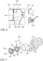
- FIGS. 6 to 8 show an exemplary embodiment of a compressor arrangement 100 according to the invention
- Fig. 6 the compressor assembly 100 is shown in a schematic sectional view
- Fig. 7 is the compressor assembly 100 shown in an exploded view
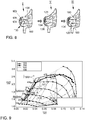
- Fig. 8 different operating positions of the compressor assembly 100 are shown in a partially perspective and partially sectional view.
- the second embodiment corresponds in essential points to the first embodiment, so that reference may be made to the above statements.
- the compressor assembly 100 is provided for installation in a fresh air train of an internal combustion engine with turbocharger.
- the exhaust gas turbocharger comprises a turbine arranged in the exhaust tract and driven by the exhaust gas (not shown) and a radial compressor driven by the turbine with the compressor impeller 150, which can be flowed in via the inflow passage 120 with fresh gas.
- an adjusting device 130 for changing a flow cross-sectional area of the inflow passage 120 is arranged.
- the adjusting device 130 comprises a diaphragm 132 fixed in the inflow channel 120 with a diaphragm opening 134 present centrally in the inflow channel and a plurality of diaphragm windows 136 which are arranged in Fig. 7 are recognizable.
- the central aperture 134 Through the central aperture 134, the fresh air enters a pipe section 139 with a predetermined trim diameter, which leads the fresh air towards a central portion of the impeller 150.
- the central trim channel formed by the central aperture 134 and the pipe section 139 is not closable, as in the first embodiment, and thus provides a minimum flow cross-sectional area for low mass flows.
- Fig. 7 extends around the central aperture 134 around an annularly substantially perpendicular to the flow direction extending diaphragm surface 135, in which the aperture window 136 are introduced.
- the aperture window 136 are formed substantially circular ring segment-like, so that the round cross-section of the inflow channel 20 can be optimally utilized.
- six aperture windows are shown, with two adjacent aperture windows each enclosing a mutual angle of approximately 60 ° and each aperture window extending through an angle of approximately 30 °.
- the diaphragm surface 135 each has annular-segment-shaped webs, which likewise each extend at an angle of approximately 30 °.
- a deviating arrangement of the aperture window is also conceivable.
- a closing member 138 in the form of a rotatably mounted annular disc, wherein the annular disc as well as the diaphragm 132 has a central opening 144 and the central opening 144 ring-like circumferential annular window 146.
- the closure member 138 serves to close and to open the aperture window 136 by twisting about the central flow axis.
- the adjustment device 130 in a second operating position II, in which all the aperture window 136 of fresh gas can be flowed through. In this position, the angular position of the aperture window 136 corresponds to that of the annular window 146.
- the pipe section 139 coaxially encircling inflow channel 125 can be flowed through the aperture window 136 with fresh gas.
- the flow path passing through the inflow passage 125 is converged radially inwardly with the tapered passage 180 of the outer wall of the inflow passage 120 at the central flow passage through the tube portion 139.
- the aperture windows are closed, while the central aperture 134 and thus the central trim channel forming tube portion 139 of fresh gas can be flowed through.
- the trim is thereby reduced, whereby the flow rate can be raised.
- the aperture windows 136 are each offset from the annular windows 146, so that they are closed by the webs between the annular windows 146.
- a particularly important feature is the supply line of an exhaust gas recirculation 170 through which exhaust gas is introduced from the exhaust tract into the fresh gas branch upstream of the compressor impeller 150.
- the exhaust gas recirculation 170 opens in the region of the adjusting device 130, and Although between the diaphragm surface 135 and the compressor impeller 150, in the inflow passage 120 a.
- the exhaust gas supplied through the exhaust gas recirculation 170 is particularly well miscible with the supplied fresh gas flowing through the central trim channel.
- the setting device 130 of the second exemplary embodiment has the following differences:
- the tube section 139 of the diaphragm 132 arranged in the flow channel 120 does not have a closed tube wall (cf. Fig. 6 for comparison purposes shown above right panel 32), but a plurality of the pipe wall passing through passages 160 in the form of holes.
- the passages 160 increase the flow area between the exhaust gas recirculation 170 and the central trim channel, thereby increasing the EGR rate.
- this modified panel 132 is shown in a lower right side view in a side view, wherein the flow-optimally shaped passages 160 can be seen.
- the passages 160 can be opened and closed by means of a cover part 162 in order to be able to set the EGR rate as required in this way.
- the cover member 162 is formed in the form of a sleeve paragraph formed integrally with the annular disk-shaped closure member 138, which protrudes into the pipe section 139 of the aperture 132 and is provided for covering the passages 160 in a closed position.
- the aperture window 136 can be opened and closed and the passages 160 can be opened and closed, which enable a fluid connection between the connection channel 125 and the central trim channel.
- the passages 160 are placed in a spatial arrangement in the wall of the tube section 139, which in combination with the spatial arrangement of the aperture window 136 allows the following three operating positions, the Fig. 8 a first operating position I (first rotational position of the closure part 138) in which both the aperture windows 136 and the passages 160 are closed by the closure part 138 or the cover part 162 protruding like a sleeve, but the central trim channel is open; a second operating position II (second rotational position of the closure member 138, here rotated by 30 ° relative to the first operating position) in which the aperture windows 136 are aligned with the annular windows 146 and are thus opened, but the passages 160 are closed by the cover 162; and a third operating position III (third rotational position of the closing part 138, here rotated by 30 ° relative to the second operating position), in which the Aperture windows 136 are closed, but the passages 160 are open to provide a high EGR rate. Stepless intermediate positions are possible.
- FIG. 9 are shown by the second embodiment achievable efficiency advantages.
- the X-axis indicates the reduced flow rate in m 3 / s (191), and the Y-axis indicates the compressor pressure ratio (192).
- the basic map is denoted by 193, the full load characteristic by 194, the difference map for the optimized variant according to embodiment 2 by 195 and the neutral line by 196.
- the advantages of the invention are particularly evident up to a speed of about 1750 min -1 . By means of the lines 197, the efficiency advantages are highlighted by optimizing the Schaufelradanströmung.
Landscapes
- Engineering & Computer Science (AREA)
- Mechanical Engineering (AREA)
- General Engineering & Computer Science (AREA)
- Chemical & Material Sciences (AREA)
- Combustion & Propulsion (AREA)
- Supercharger (AREA)
- Structures Of Non-Positive Displacement Pumps (AREA)
Claims (16)
- Agencement de compresseur (100) pour un moteur à combustion interne, comprenant un rotor de compresseur (150), un canal d'afflux (120) disposé en amont du rotor de compresseur (150) et un dispositif d'ajustement (130) pour faire varier une section transversale d'écoulement du canal d'afflux (120), le dispositif d'ajustement (130) présentant un diaphragme (132) disposé dans le canal d'afflux (120) avec une fenêtre de diaphragme centrale (134) et au moins une ouverture de diaphragme supplémentaire sous la forme d'une fenêtre de diaphragme (136) pouvant être au moins en partie fermée et l'ouverture de diaphragme centrale (134) constituant une portion tubulaire (139) débouchant vers une portion centrale du rotor de compresseur (150), un canal de connexion (125) entourant sous forme annulaire la portion tubulaire étant formé entre une paroi interne du canal d'afflux (120) et une paroi externe de la portion tubulaire, lequel canal de connexion peut recevoir l'écoulement par le biais de l'au moins une fenêtre de diaphragme pouvant être fermée (136), caractérisé en ce qu'un ou plusieurs passages d'écoulement (160) sont réalisés dans la paroi extérieure de la portion tubulaire (139).
- Agencement de compresseur selon la revendication 1, caractérisé en ce que le diaphragme (132) présente deux, trois ou plus de trois, en particulier environ six fenêtres de diaphragme (136) pouvant être fermées, qui sont disposées sous forme annulaire autour de l'ouverture de diaphragme centrale (134).
- Agencement de compresseur selon la revendication 2, caractérisé en ce que parmi les n fenêtres de diaphragme (136), deux fenêtres de diaphragme adjacentes forment à chaque fois un angle d'environ 360°/n et/ou chaque fenêtre de diaphragme est prévue en forme de segment de cercle annulaire avec un angle de segment de 360°/2n.
- Agencement de compresseur selon au moins l'une quelconque des revendications précédentes, caractérisé en ce que les fenêtres de diaphragme (136) peuvent de préférence être partiellement ou complètement fermées ou ouvertes, de préférence simultanément, par déplacement, en particulier par rotation, d'une partie de fermeture mobile (138) par rapport au diaphragme fixe (132) dans le canal d'afflux.
- Agencement de compresseur selon la revendication 4, caractérisé en ce que la partie de fermeture (138) est un disque annulaire rotatif pouvant être appliqué contre une surface de diaphragme (135) s'étendant approximativement perpendiculairement à la direction d'écoulement, avec une ouverture annulaire centrale (144) adaptée à l'ouverture de diaphragme centrale (134) et avec des fenêtres annulaires (146) adaptées aux fenêtres de diaphragme (136), entourant à chaque fois en partie l'ouverture annulaire centrale.
- Agencement de compresseur selon l'une quelconque des revendications précédentes, caractérisé en ce que le ou les passages d'écoulement (160) sont prévus dans la paroi extérieure de la portion tubulaire (139) de manière à pouvoir être fermés.
- Agencement de compresseur selon l'une quelconque des revendications précédentes, caractérisé en ce que les passages d'écoulement (160) peuvent être fermés ou ouverts partiellement ou complètement de préférence simultanément, par déplacement, en particulier par rotation, d'une partie de recouvrement mobile (162) par rapport au diaphragme fixe (132) dans le canal d'afflux.
- Agencement de compresseur selon les revendications 4 à 7, caractérisé en ce que la partie de fermeture (138) est formée d'une seule pièce avec la partie de recouvrement (162), la partie de recouvrement pénétrant à la manière d'un épaulement de douille dans la portion tubulaire (139) à partir de la partie de fermeture.
- Agencement de compresseur selon l'une quelconque des revendications 6 à 8, caractérisé en ce que l'agencement de compresseur peut être déplacé dans une première position de fonctionnement (I) dans laquelle à la fois la fenêtre de diaphragme (136) et les passages tubulaires (160) sont fermés pour empêcher un écoulement, dans une deuxième position de fonctionnement (II) dans laquelle au moins une, et de préférence toutes les fenêtres de diaphragme (136) sont ouvertes et au moins un et de préférence tous les passages tubulaires (160) sont fermés, et/ou dans une troisième position de fonctionnement (III) dans laquelle au moins une et de préférence toutes les fenêtres de diaphragme (136) sont fermées et au moins un et de préférence tous les passages tubulaires (160) sont ouverts.
- Agencement de compresseur selon au moins l'une quelconque des revendications précédentes, caractérisé par une recirculation de gaz d'échappement (170) par le biais de laquelle du gaz d'échappement peut être introduit dans le canal d'afflux (120) en amont du rotor de compresseur (150) dans la région du dispositif d'ajustement (130), de préférence en aval de la fenêtre de diaphragme (136).
- Agencement de compresseur selon la revendication 10, caractérisé en ce que la recirculation de gaz d'échappement (170) débouche dans le canal de connexion (125).
- Agencement de compresseur selon la revendication 10 ou 11, caractérisé en ce que le dispositif d'ajustement (130) est prévu pour modifier une section transversale d'écoulement entre la recirculation de gaz d'échappement et le rotor de compresseur.
- Agencement de compresseur selon l'une quelconque des revendications précédentes, caractérisé par un rétrécissement en forme d'entonnoir (180) du canal d'afflux (120) en aval du diaphragme (132) et en amont du rotor de compresseur (150), le plus petit diamètre d'écoulement (D) du rétrécissement (180) correspondant de préférence essentiellement au diamètre de la portion tubulaire (139) et/ou étant disposé directement en aval de l'extrémité de la portion tubulaire (139) tournée vers le rotor de compresseur (150), de telle sorte que le rétrécissement (180) délimite le canal de connexion (125) vers l'aval.
- Agencement de compresseur selon l'une quelconque des revendications précédentes, caractérisé par un E-booster à commande électrique pour augmenter une pression de suralimentation pouvant être fournie par l'agencement de compresseur.
- Moteur à combustion interne comprenant un moteur à combustion, un ligne d'échappement, une ligne de gaz d'échappement, une ligne de gaz frais et un turbocompresseur à gaz d'échappement avec une turbine intégrée dans la ligne de gaz d'échappement et un agencement de compresseur (100) selon l'une quelconque des revendications précédentes intégré dans la ligne de gaz frais.
- Procédé pour faire fonctionner un moteur à combustion interne selon la revendication 15, qui comprend un agencement de compresseur (100) selon la revendication 10 ou selon l'une quelconque des revendications dépendant de la revendication 10, dans lequel une quantité de flux de gaz d'échappement à travers la recirculation des gaz d'échappement (170) débouchant en amont du rotor de compresseur (150) dans la ligne de gaz frais est ajustée au moyen du dispositif d'ajustement (130) de l'agencement de compresseur et de préférence pas au moyen d'un clapet de gaz d'échappement.
Applications Claiming Priority (2)
| Application Number | Priority Date | Filing Date | Title |
|---|---|---|---|
| DE102015201768 | 2015-02-02 | ||
| DE102015209704.8A DE102015209704A1 (de) | 2015-02-02 | 2015-05-27 | Verdichter mit variabler Anströmgeometrie |
Publications (2)
| Publication Number | Publication Date |
|---|---|
| EP3051099A1 EP3051099A1 (fr) | 2016-08-03 |
| EP3051099B1 true EP3051099B1 (fr) | 2017-11-08 |
Family
ID=55069662
Family Applications (1)
| Application Number | Title | Priority Date | Filing Date |
|---|---|---|---|
| EP15199551.1A Not-in-force EP3051099B1 (fr) | 2015-02-02 | 2015-12-11 | Compresseur à géometrie d'écoulement variable |
Country Status (1)
| Country | Link |
|---|---|
| EP (1) | EP3051099B1 (fr) |
Cited By (4)
| Publication number | Priority date | Publication date | Assignee | Title |
|---|---|---|---|---|
| US20180258842A1 (en) * | 2017-03-10 | 2018-09-13 | Honeywell International Inc. | Adjustable-trim centrifugal compressor for a turbocharger |
| CN110685795A (zh) * | 2018-07-05 | 2020-01-14 | 大众汽车有限公司 | 用于运行机动车的方法和机动车 |
| US11300043B2 (en) * | 2018-10-10 | 2022-04-12 | Vitesco Technologies GmbH | Internal combustion engine comprising a turbocharger with variability at the compressor inlet |
| US12553450B2 (en) | 2024-05-23 | 2026-02-17 | Pratt & Whitney Canada Corp. | Plenum closure panel with integrated airflow direction device |
Families Citing this family (12)
| Publication number | Priority date | Publication date | Assignee | Title |
|---|---|---|---|---|
| DE102014216162B4 (de) * | 2014-08-14 | 2019-01-17 | Ford Global Technologies, Llc | Aufgeladene Brennkraftmaschine mit Abgasturbolader und Verfahren zum Betreiben einer derartigen Brennkraftmaschine |
| FR3069022B1 (fr) * | 2017-07-11 | 2021-05-21 | Renault Sas | Procede de commande d'un moteur a combustion interne suralimente. |
| PL423333A1 (pl) * | 2017-11-01 | 2019-05-06 | Szymanski Piotr | Kartridż do zmiany przekroju wlotu kompresora |
| DE102018211094A1 (de) * | 2018-07-05 | 2020-01-09 | Volkswagen Aktiengesellschaft | Verfahren zum Betreiben einer Brennkraftmaschine, Brennkraftmaschine und Kraftfahrzeug |
| DE102018211091B4 (de) * | 2018-07-05 | 2025-12-24 | Volkswagen Aktiengesellschaft | Verfahren zum Betreiben einer Brennkraftmaschine und Brennkraftmaschine |
| DE102018212756B3 (de) * | 2018-07-31 | 2019-10-31 | Continental Automotive Gmbh | Radialverdichter, Aufladevorrichtung und Brennkraftmaschine mit Abgasrückführeinrichtung |
| DE102018221147B4 (de) | 2018-12-06 | 2022-06-23 | Ford Global Technologies, Llc | Aufgeladene Brennkraftmaschine mit Verdichter und stromaufwärts des Verdichters angeordneter Leiteinrichtung |
| US11725668B2 (en) | 2019-03-19 | 2023-08-15 | Mitsubishi Heavy Industries Engine & Turbocharger, Ltd. | Centrifugal compressor and turbocharger |
| JP7353354B2 (ja) | 2019-03-19 | 2023-09-29 | 三菱重工エンジン&ターボチャージャ株式会社 | 遠心圧縮機及びターボチャージャ |
| JP7351903B2 (ja) | 2019-03-19 | 2023-09-27 | 三菱重工エンジン&ターボチャージャ株式会社 | 遠心圧縮機及びターボチャージャ |
| DE202019103660U1 (de) * | 2019-07-03 | 2020-10-06 | Borgwarner Inc. | Verstellmechanismus für einen Verdichter |
| CN112282923B (zh) * | 2020-11-12 | 2021-11-16 | 湖南路捷道夫涡轮增压系统有限公司 | 一种可变截面涡轮增压器 |
Family Cites Families (6)
| Publication number | Priority date | Publication date | Assignee | Title |
|---|---|---|---|---|
| DE102010026176B4 (de) | 2010-07-06 | 2015-12-17 | Iav Gmbh Ingenieurgesellschaft Auto Und Verkehr | Vorrichtung und Verfahren zur Kennfeldstabilisierung eines Verdichters |
| DE102011121996B4 (de) | 2011-12-23 | 2013-07-11 | Iav Gmbh Ingenieurgesellschaft Auto Und Verkehr | Vorrichtung zum Betrieb eines Verdichters |
| DE102013003418A1 (de) | 2013-02-28 | 2014-08-28 | Volkswagen Aktiengesellschaft | Brennkraftmaschine |
| DE102013006928A1 (de) | 2013-04-22 | 2014-10-23 | Volkswagen Aktiengesellschaft | Abgasturbolader |
| US10107296B2 (en) * | 2013-06-25 | 2018-10-23 | Ford Global Technologies, Llc | Turbocharger systems and method to prevent compressor choke |
| CN105358837B (zh) * | 2013-07-04 | 2018-03-20 | 三菱重工业株式会社 | 离心压缩机 |
-
2015
- 2015-12-11 EP EP15199551.1A patent/EP3051099B1/fr not_active Not-in-force
Non-Patent Citations (1)
| Title |
|---|
| None * |
Cited By (6)
| Publication number | Priority date | Publication date | Assignee | Title |
|---|---|---|---|---|
| US20180258842A1 (en) * | 2017-03-10 | 2018-09-13 | Honeywell International Inc. | Adjustable-trim centrifugal compressor for a turbocharger |
| US10502126B2 (en) * | 2017-03-10 | 2019-12-10 | Garrett Transportation I Inc. | Adjustable-trim centrifugal compressor for a turbocharger |
| CN110685795A (zh) * | 2018-07-05 | 2020-01-14 | 大众汽车有限公司 | 用于运行机动车的方法和机动车 |
| CN110685795B (zh) * | 2018-07-05 | 2021-12-24 | 大众汽车有限公司 | 用于运行机动车的方法和机动车 |
| US11300043B2 (en) * | 2018-10-10 | 2022-04-12 | Vitesco Technologies GmbH | Internal combustion engine comprising a turbocharger with variability at the compressor inlet |
| US12553450B2 (en) | 2024-05-23 | 2026-02-17 | Pratt & Whitney Canada Corp. | Plenum closure panel with integrated airflow direction device |
Also Published As
| Publication number | Publication date |
|---|---|
| EP3051099A1 (fr) | 2016-08-03 |
Similar Documents
| Publication | Publication Date | Title |
|---|---|---|
| EP3051099B1 (fr) | Compresseur à géometrie d'écoulement variable | |
| DE102015209704A1 (de) | Verdichter mit variabler Anströmgeometrie | |
| EP1766209B1 (fr) | Moteur a combustion interne pourvu d'une turbosoufflante a gaz d'echappement | |
| EP2025896B1 (fr) | Compresseur radial pour turbocompresseur | |
| EP1488084B1 (fr) | Turbocompresseur a gaz d'echappement a geometrie variable | |
| EP3542069B1 (fr) | Compresseur, turbocompresseur et moteur a combustion interne | |
| WO2009129895A1 (fr) | Turbocompresseur pour un moteur à combustion interne d'un véhicule et moteur à combustion interne | |
| DE102008049782A1 (de) | Abgasturbolader für eine Brennkraftmaschine | |
| EP3026238B1 (fr) | Moteur à combustion interne avec un turbocompresseur | |
| WO2020120254A1 (fr) | Turbine à gaz d'échappement à géométrie variable pour un turbocompresseur | |
| DE102004029830A1 (de) | Turbinenrad in einer Abgasturbine eines Abgasturboladers | |
| DE102011120167A1 (de) | Verdichter für einen Abgasturbolader,insbesondere eines Kraftwagens | |
| WO1999000590A1 (fr) | Systeme turbocompresseur pour moteurs a combustion interne | |
| DE102015203551A1 (de) | Abgasturboladeranordnung für ein Kraftfahrzeug | |
| DE10132672A1 (de) | Abgasturbolader für eine Brennkraftmaschine | |
| DE102017216256B3 (de) | Verdichter für eine Aufladevorrichtung einer Brennkraftmaschine und Aufladevorrichtung für eine Brennkraftmaschine | |
| EP2024618B1 (fr) | Turbocompresseur pour un moteur à combustion interne | |
| DE102017219165B4 (de) | Verdichter, Abgasturbolader und Brennkraftmaschine | |
| DE102014226341A1 (de) | Verdichter, Abgasturbolader und Brennkraftmaschine | |
| DE102011111747A1 (de) | Verdichter für einen Abgasturbolader | |
| EP3139045B1 (fr) | Compresseur, turbocompresseur à gaz d'échappement et moteur a combustion interne | |
| DE102018212756B3 (de) | Radialverdichter, Aufladevorrichtung und Brennkraftmaschine mit Abgasrückführeinrichtung | |
| WO2012136234A1 (fr) | Turbine pour un turbocompresseur sur gaz d'échappement, ainsi que moteur à combustion interne équipé d'une telle turbine | |
| DE19514707A1 (de) | Vorleiteinrichtung für Radialverdichter | |
| DE102012006673B4 (de) | Verdichter für einen Abgasturbolader, insbesondere eines Kraftwagens |
Legal Events
| Date | Code | Title | Description |
|---|---|---|---|
| PUAI | Public reference made under article 153(3) epc to a published international application that has entered the european phase |
Free format text: ORIGINAL CODE: 0009012 |
|
| AK | Designated contracting states |
Kind code of ref document: A1 Designated state(s): AL AT BE BG CH CY CZ DE DK EE ES FI FR GB GR HR HU IE IS IT LI LT LU LV MC MK MT NL NO PL PT RO RS SE SI SK SM TR |
|
| AX | Request for extension of the european patent |
Extension state: BA ME |
|
| 17P | Request for examination filed |
Effective date: 20170203 |
|
| RBV | Designated contracting states (corrected) |
Designated state(s): AL AT BE BG CH CY CZ DE DK EE ES FI FR GB GR HR HU IE IS IT LI LT LU LV MC MK MT NL NO PL PT RO RS SE SI SK SM TR |
|
| GRAP | Despatch of communication of intention to grant a patent |
Free format text: ORIGINAL CODE: EPIDOSNIGR1 |
|
| RIC1 | Information provided on ipc code assigned before grant |
Ipc: F04D 29/46 20060101ALI20170630BHEP Ipc: F02M 26/06 20160101ALI20170630BHEP Ipc: F04D 29/44 20060101ALI20170630BHEP Ipc: F02B 39/10 20060101ALN20170630BHEP Ipc: F04D 27/02 20060101ALI20170630BHEP Ipc: F04D 29/42 20060101ALI20170630BHEP Ipc: F04D 27/00 20060101ALI20170630BHEP Ipc: F02B 37/10 20060101ALN20170630BHEP Ipc: F02M 26/09 20160101ALI20170630BHEP Ipc: F01D 17/14 20060101ALI20170630BHEP Ipc: F02B 37/22 20060101AFI20170630BHEP |
|
| INTG | Intention to grant announced |
Effective date: 20170727 |
|
| RIN1 | Information on inventor provided before grant (corrected) |
Inventor name: FRERICHS, SIMON Inventor name: WERNER, RONNY Inventor name: ALBERTI, PETER, DR. Inventor name: GREINER, MICHAEL Inventor name: KLEINEN, MARCUS Inventor name: KAMMEYER, JASPER Inventor name: HINRICHS, OLIVER |
|
| GRAS | Grant fee paid |
Free format text: ORIGINAL CODE: EPIDOSNIGR3 |
|
| GRAA | (expected) grant |
Free format text: ORIGINAL CODE: 0009210 |
|
| AK | Designated contracting states |
Kind code of ref document: B1 Designated state(s): AL AT BE BG CH CY CZ DE DK EE ES FI FR GB GR HR HU IE IS IT LI LT LU LV MC MK MT NL NO PL PT RO RS SE SI SK SM TR |
|
| REG | Reference to a national code |
Ref country code: GB Ref legal event code: FG4D Free format text: NOT ENGLISH |
|
| REG | Reference to a national code |
Ref country code: CH Ref legal event code: EP Ref country code: AT Ref legal event code: REF Ref document number: 944378 Country of ref document: AT Kind code of ref document: T Effective date: 20171115 |
|
| REG | Reference to a national code |
Ref country code: IE Ref legal event code: FG4D Free format text: LANGUAGE OF EP DOCUMENT: GERMAN |
|
| REG | Reference to a national code |
Ref country code: DE Ref legal event code: R096 Ref document number: 502015002300 Country of ref document: DE |
|
| REG | Reference to a national code |
Ref country code: FR Ref legal event code: PLFP Year of fee payment: 3 |
|
| REG | Reference to a national code |
Ref country code: NL Ref legal event code: MP Effective date: 20171108 |
|
| REG | Reference to a national code |
Ref country code: LT Ref legal event code: MG4D |
|
| PG25 | Lapsed in a contracting state [announced via postgrant information from national office to epo] |
Ref country code: NO Free format text: LAPSE BECAUSE OF FAILURE TO SUBMIT A TRANSLATION OF THE DESCRIPTION OR TO PAY THE FEE WITHIN THE PRESCRIBED TIME-LIMIT Effective date: 20180208 Ref country code: ES Free format text: LAPSE BECAUSE OF FAILURE TO SUBMIT A TRANSLATION OF THE DESCRIPTION OR TO PAY THE FEE WITHIN THE PRESCRIBED TIME-LIMIT Effective date: 20171108 Ref country code: NL Free format text: LAPSE BECAUSE OF FAILURE TO SUBMIT A TRANSLATION OF THE DESCRIPTION OR TO PAY THE FEE WITHIN THE PRESCRIBED TIME-LIMIT Effective date: 20171108 Ref country code: LT Free format text: LAPSE BECAUSE OF FAILURE TO SUBMIT A TRANSLATION OF THE DESCRIPTION OR TO PAY THE FEE WITHIN THE PRESCRIBED TIME-LIMIT Effective date: 20171108 Ref country code: SE Free format text: LAPSE BECAUSE OF FAILURE TO SUBMIT A TRANSLATION OF THE DESCRIPTION OR TO PAY THE FEE WITHIN THE PRESCRIBED TIME-LIMIT Effective date: 20171108 Ref country code: FI Free format text: LAPSE BECAUSE OF FAILURE TO SUBMIT A TRANSLATION OF THE DESCRIPTION OR TO PAY THE FEE WITHIN THE PRESCRIBED TIME-LIMIT Effective date: 20171108 |
|
| PG25 | Lapsed in a contracting state [announced via postgrant information from national office to epo] |
Ref country code: HR Free format text: LAPSE BECAUSE OF FAILURE TO SUBMIT A TRANSLATION OF THE DESCRIPTION OR TO PAY THE FEE WITHIN THE PRESCRIBED TIME-LIMIT Effective date: 20171108 Ref country code: LV Free format text: LAPSE BECAUSE OF FAILURE TO SUBMIT A TRANSLATION OF THE DESCRIPTION OR TO PAY THE FEE WITHIN THE PRESCRIBED TIME-LIMIT Effective date: 20171108 Ref country code: RS Free format text: LAPSE BECAUSE OF FAILURE TO SUBMIT A TRANSLATION OF THE DESCRIPTION OR TO PAY THE FEE WITHIN THE PRESCRIBED TIME-LIMIT Effective date: 20171108 Ref country code: GR Free format text: LAPSE BECAUSE OF FAILURE TO SUBMIT A TRANSLATION OF THE DESCRIPTION OR TO PAY THE FEE WITHIN THE PRESCRIBED TIME-LIMIT Effective date: 20180209 Ref country code: IS Free format text: LAPSE BECAUSE OF FAILURE TO SUBMIT A TRANSLATION OF THE DESCRIPTION OR TO PAY THE FEE WITHIN THE PRESCRIBED TIME-LIMIT Effective date: 20180308 Ref country code: BG Free format text: LAPSE BECAUSE OF FAILURE TO SUBMIT A TRANSLATION OF THE DESCRIPTION OR TO PAY THE FEE WITHIN THE PRESCRIBED TIME-LIMIT Effective date: 20180208 |
|
| PG25 | Lapsed in a contracting state [announced via postgrant information from national office to epo] |
Ref country code: CZ Free format text: LAPSE BECAUSE OF FAILURE TO SUBMIT A TRANSLATION OF THE DESCRIPTION OR TO PAY THE FEE WITHIN THE PRESCRIBED TIME-LIMIT Effective date: 20171108 Ref country code: SK Free format text: LAPSE BECAUSE OF FAILURE TO SUBMIT A TRANSLATION OF THE DESCRIPTION OR TO PAY THE FEE WITHIN THE PRESCRIBED TIME-LIMIT Effective date: 20171108 Ref country code: EE Free format text: LAPSE BECAUSE OF FAILURE TO SUBMIT A TRANSLATION OF THE DESCRIPTION OR TO PAY THE FEE WITHIN THE PRESCRIBED TIME-LIMIT Effective date: 20171108 Ref country code: CY Free format text: LAPSE BECAUSE OF FAILURE TO SUBMIT A TRANSLATION OF THE DESCRIPTION OR TO PAY THE FEE WITHIN THE PRESCRIBED TIME-LIMIT Effective date: 20171108 Ref country code: DK Free format text: LAPSE BECAUSE OF FAILURE TO SUBMIT A TRANSLATION OF THE DESCRIPTION OR TO PAY THE FEE WITHIN THE PRESCRIBED TIME-LIMIT Effective date: 20171108 |
|
| REG | Reference to a national code |
Ref country code: DE Ref legal event code: R097 Ref document number: 502015002300 Country of ref document: DE |
|
| PG25 | Lapsed in a contracting state [announced via postgrant information from national office to epo] |
Ref country code: RO Free format text: LAPSE BECAUSE OF FAILURE TO SUBMIT A TRANSLATION OF THE DESCRIPTION OR TO PAY THE FEE WITHIN THE PRESCRIBED TIME-LIMIT Effective date: 20171108 Ref country code: IT Free format text: LAPSE BECAUSE OF FAILURE TO SUBMIT A TRANSLATION OF THE DESCRIPTION OR TO PAY THE FEE WITHIN THE PRESCRIBED TIME-LIMIT Effective date: 20171108 Ref country code: PL Free format text: LAPSE BECAUSE OF FAILURE TO SUBMIT A TRANSLATION OF THE DESCRIPTION OR TO PAY THE FEE WITHIN THE PRESCRIBED TIME-LIMIT Effective date: 20171108 Ref country code: SM Free format text: LAPSE BECAUSE OF FAILURE TO SUBMIT A TRANSLATION OF THE DESCRIPTION OR TO PAY THE FEE WITHIN THE PRESCRIBED TIME-LIMIT Effective date: 20171108 |
|
| PLBE | No opposition filed within time limit |
Free format text: ORIGINAL CODE: 0009261 |
|
| STAA | Information on the status of an ep patent application or granted ep patent |
Free format text: STATUS: NO OPPOSITION FILED WITHIN TIME LIMIT |
|
| REG | Reference to a national code |
Ref country code: IE Ref legal event code: MM4A |
|
| PG25 | Lapsed in a contracting state [announced via postgrant information from national office to epo] |
Ref country code: MT Free format text: LAPSE BECAUSE OF FAILURE TO SUBMIT A TRANSLATION OF THE DESCRIPTION OR TO PAY THE FEE WITHIN THE PRESCRIBED TIME-LIMIT Effective date: 20171108 Ref country code: LU Free format text: LAPSE BECAUSE OF NON-PAYMENT OF DUE FEES Effective date: 20171211 |
|
| 26N | No opposition filed |
Effective date: 20180809 |
|
| REG | Reference to a national code |
Ref country code: BE Ref legal event code: MM Effective date: 20171231 |
|
| PG25 | Lapsed in a contracting state [announced via postgrant information from national office to epo] |
Ref country code: IE Free format text: LAPSE BECAUSE OF NON-PAYMENT OF DUE FEES Effective date: 20171211 |
|
| PG25 | Lapsed in a contracting state [announced via postgrant information from national office to epo] |
Ref country code: BE Free format text: LAPSE BECAUSE OF NON-PAYMENT OF DUE FEES Effective date: 20171231 Ref country code: SI Free format text: LAPSE BECAUSE OF FAILURE TO SUBMIT A TRANSLATION OF THE DESCRIPTION OR TO PAY THE FEE WITHIN THE PRESCRIBED TIME-LIMIT Effective date: 20171108 |
|
| PG25 | Lapsed in a contracting state [announced via postgrant information from national office to epo] |
Ref country code: HU Free format text: LAPSE BECAUSE OF FAILURE TO SUBMIT A TRANSLATION OF THE DESCRIPTION OR TO PAY THE FEE WITHIN THE PRESCRIBED TIME-LIMIT; INVALID AB INITIO Effective date: 20151211 Ref country code: MC Free format text: LAPSE BECAUSE OF FAILURE TO SUBMIT A TRANSLATION OF THE DESCRIPTION OR TO PAY THE FEE WITHIN THE PRESCRIBED TIME-LIMIT Effective date: 20171108 |
|
| REG | Reference to a national code |
Ref country code: CH Ref legal event code: PL |
|
| PG25 | Lapsed in a contracting state [announced via postgrant information from national office to epo] |
Ref country code: MK Free format text: LAPSE BECAUSE OF FAILURE TO SUBMIT A TRANSLATION OF THE DESCRIPTION OR TO PAY THE FEE WITHIN THE PRESCRIBED TIME-LIMIT Effective date: 20171108 |
|
| PG25 | Lapsed in a contracting state [announced via postgrant information from national office to epo] |
Ref country code: CH Free format text: LAPSE BECAUSE OF NON-PAYMENT OF DUE FEES Effective date: 20181231 Ref country code: LI Free format text: LAPSE BECAUSE OF NON-PAYMENT OF DUE FEES Effective date: 20181231 |
|
| PG25 | Lapsed in a contracting state [announced via postgrant information from national office to epo] |
Ref country code: TR Free format text: LAPSE BECAUSE OF FAILURE TO SUBMIT A TRANSLATION OF THE DESCRIPTION OR TO PAY THE FEE WITHIN THE PRESCRIBED TIME-LIMIT Effective date: 20171108 |
|
| PG25 | Lapsed in a contracting state [announced via postgrant information from national office to epo] |
Ref country code: PT Free format text: LAPSE BECAUSE OF FAILURE TO SUBMIT A TRANSLATION OF THE DESCRIPTION OR TO PAY THE FEE WITHIN THE PRESCRIBED TIME-LIMIT Effective date: 20171108 |
|
| PG25 | Lapsed in a contracting state [announced via postgrant information from national office to epo] |
Ref country code: AL Free format text: LAPSE BECAUSE OF FAILURE TO SUBMIT A TRANSLATION OF THE DESCRIPTION OR TO PAY THE FEE WITHIN THE PRESCRIBED TIME-LIMIT Effective date: 20171108 |
|
| REG | Reference to a national code |
Ref country code: AT Ref legal event code: MM01 Ref document number: 944378 Country of ref document: AT Kind code of ref document: T Effective date: 20201211 |
|
| PG25 | Lapsed in a contracting state [announced via postgrant information from national office to epo] |
Ref country code: AT Free format text: LAPSE BECAUSE OF NON-PAYMENT OF DUE FEES Effective date: 20201211 |
|
| P01 | Opt-out of the competence of the unified patent court (upc) registered |
Effective date: 20230523 |
|
| PGFP | Annual fee paid to national office [announced via postgrant information from national office to epo] |
Ref country code: GB Payment date: 20231219 Year of fee payment: 9 |
|
| PGFP | Annual fee paid to national office [announced via postgrant information from national office to epo] |
Ref country code: FR Payment date: 20231226 Year of fee payment: 9 Ref country code: DE Payment date: 20231231 Year of fee payment: 9 |
|
| REG | Reference to a national code |
Ref country code: DE Ref legal event code: R119 Ref document number: 502015002300 Country of ref document: DE |
|
| GBPC | Gb: european patent ceased through non-payment of renewal fee |
Effective date: 20241211 |
|
| PG25 | Lapsed in a contracting state [announced via postgrant information from national office to epo] |
Ref country code: DE Free format text: LAPSE BECAUSE OF NON-PAYMENT OF DUE FEES Effective date: 20250701 |
|
| PG25 | Lapsed in a contracting state [announced via postgrant information from national office to epo] |
Ref country code: GB Free format text: LAPSE BECAUSE OF NON-PAYMENT OF DUE FEES Effective date: 20241211 |
|
| PG25 | Lapsed in a contracting state [announced via postgrant information from national office to epo] |
Ref country code: FR Free format text: LAPSE BECAUSE OF NON-PAYMENT OF DUE FEES Effective date: 20241231 |