EP3051627A1 - Appareil antenne et terminal - Google Patents
Appareil antenne et terminal Download PDFInfo
- Publication number
- EP3051627A1 EP3051627A1 EP14845756.7A EP14845756A EP3051627A1 EP 3051627 A1 EP3051627 A1 EP 3051627A1 EP 14845756 A EP14845756 A EP 14845756A EP 3051627 A1 EP3051627 A1 EP 3051627A1
- Authority
- EP
- European Patent Office
- Prior art keywords
- antenna
- radiation
- support arm
- radiation support
- feed part
- Prior art date
- Legal status (The legal status is an assumption and is not a legal conclusion. Google has not performed a legal analysis and makes no representation as to the accuracy of the status listed.)
- Withdrawn
Links
- 230000005855 radiation Effects 0.000 claims abstract description 110
- 238000004891 communication Methods 0.000 description 10
- 238000010586 diagram Methods 0.000 description 4
- 230000005540 biological transmission Effects 0.000 description 3
- 238000010295 mobile communication Methods 0.000 description 3
- 230000000903 blocking effect Effects 0.000 description 2
- 238000000034 method Methods 0.000 description 2
- 206010048669 Terminal state Diseases 0.000 description 1
- 238000005452 bending Methods 0.000 description 1
- 230000008094 contradictory effect Effects 0.000 description 1
- 230000003247 decreasing effect Effects 0.000 description 1
- 230000003287 optical effect Effects 0.000 description 1
- 230000002093 peripheral effect Effects 0.000 description 1
- 239000000843 powder Substances 0.000 description 1
Images


Classifications
-
- H—ELECTRICITY
- H01—ELECTRIC ELEMENTS
- H01Q—ANTENNAS, i.e. RADIO AERIALS
- H01Q1/00—Details of, or arrangements associated with, antennas
- H01Q1/12—Supports; Mounting means
- H01Q1/22—Supports; Mounting means by structural association with other equipment or articles
- H01Q1/24—Supports; Mounting means by structural association with other equipment or articles with receiving set
- H01Q1/241—Supports; Mounting means by structural association with other equipment or articles with receiving set used in mobile communications, e.g. GSM
- H01Q1/242—Supports; Mounting means by structural association with other equipment or articles with receiving set used in mobile communications, e.g. GSM specially adapted for hand-held use
- H01Q1/243—Supports; Mounting means by structural association with other equipment or articles with receiving set used in mobile communications, e.g. GSM specially adapted for hand-held use with built-in antennas
-
- H—ELECTRICITY
- H01—ELECTRIC ELEMENTS
- H01Q—ANTENNAS, i.e. RADIO AERIALS
- H01Q1/00—Details of, or arrangements associated with, antennas
- H01Q1/48—Earthing means; Earth screens; Counterpoises
-
- H—ELECTRICITY
- H01—ELECTRIC ELEMENTS
- H01Q—ANTENNAS, i.e. RADIO AERIALS
- H01Q5/00—Arrangements for simultaneous operation of antennas on two or more different wavebands, e.g. dual-band or multi-band arrangements
- H01Q5/30—Arrangements for providing operation on different wavebands
- H01Q5/307—Individual or coupled radiating elements, each element being fed in an unspecified way
- H01Q5/342—Individual or coupled radiating elements, each element being fed in an unspecified way for different propagation modes
- H01Q5/357—Individual or coupled radiating elements, each element being fed in an unspecified way for different propagation modes using a single feed point
- H01Q5/364—Creating multiple current paths
- H01Q5/371—Branching current paths
-
- H—ELECTRICITY
- H01—ELECTRIC ELEMENTS
- H01Q—ANTENNAS, i.e. RADIO AERIALS
- H01Q9/00—Electrically-short antennas having dimensions not more than twice the operating wavelength and consisting of conductive active radiating elements
- H01Q9/04—Resonant antennas
- H01Q9/30—Resonant antennas with feed to end of elongated active element, e.g. unipole
- H01Q9/42—Resonant antennas with feed to end of elongated active element, e.g. unipole with folded element, the folded parts being spaced apart a small fraction of the operating wavelength
Definitions
- the present disclosure relates to the field of communications, and in particular to an antenna device and a terminal.
- the determination of the transmitting power of a communication terminal such as a mobile phone is designed to be more and more complicated in such protocols as Global System for Mobile Communications (GSM), Code Division Multiple Access (CDMA) 20001x and Wideband Code Division Multiple Access (WCDMA), and obviously, the determination of the transmitting power is of great importance.
- GSM Global System for Mobile Communications
- CDMA Code Division Multiple Access
- WCDMA Wideband Code Division Multiple Access
- the determination of the transmitting power is of great importance.
- GSM Global System for Mobile Communications
- CDMA Code Division Multiple Access
- WCDMA Wideband Code Division Multiple Access
- the transmitting power of the mobile phone is lower, the power consumption of the mobile phone is lower, and the standby time and the talk time are longer.
- the transmitting power of the mobile phone is lower, the interference on other mobile phones in the same system is lower, which not only creates a good wireless environment for other mobile phones in the same system, but also provides a high cell capacity for CDMA20001x and WCDMA.
- the transmitting power of the mobile phone is lower, the interference on other wireless equipment is lower, and this creates a good wireless environment for other wireless equipment.
- the transmitting power of the mobile phone needs to be increased
- the transmitting power of the mobile phone needs to be high enough to overcome attenuation, caused by long-distance transmission, of the signal. Furthermore, if the signal of the mobile phone is blocked by a building or other obstacles, the transmitting power of the mobile phone needs to be high enough in a wireless shadow area to overcome attenuation, caused by reflection, refraction and long-distance transmission for multiple times, of the signal of the mobile phone. Under a condition of higher interference, such as interference and blocking between adjacent channels or interference and blocking within the current channel, the transmitting power of the mobile phone also needs to be high enough to overcome interference of noise.
- the transmitting power of the mobile phone had better be controlled according to the actual situation, specifically, when high transmitting power is needed, the transmitting power of the mobile phone is increased, and when low transmitting power is needed, the transmitting power of the mobile phone is decreased.
- a traditional antenna of a mobile terminal has good OTA performance under a state of a free space.
- a hand or the head of the user may get close to the terminal, and this may change the radiation field of the antenna. Part of energy is absorbed away, and part of energy deviates from a given radiation frequency band, so that the receiving performance and the radiation performance of the mobile phone are reduced, and the satisfaction degree of user experience is lowered.
- the embodiments of the present disclosure provide an antenna device and a terminal, so as to solve the problem that the satisfaction degree of user experience is lowered as the receiving performance and radiation performance are reduced when the antenna device of an existing terminal gets close to a part of the body of a user.
- an embodiment of the present disclosure provides an antenna device, including an antenna body, wherein the antenna body includes an antenna radiation body, and a first feed part and a first grounding part which are arranged on the antenna radiation body; the first feed part and the first grounding part are separately arranged on a same side of the antenna radiation body, and a gap between the first feed part and the first grounding part forms a groove configured to adjust a low-frequency bandwidth.
- the antenna radiation body includes a first radiation support arm and a second radiation support arm; after being connected in parallel at one ends of the first radiation support arm and the second radiation support arm, the first radiation support arm and the second radiation support arm, as a whole, are connected with the first feed part and the first grounding part respectively; the other ends of the first radiation support arm and the second radiation support arm respectively extend along a same direction.
- the first radiation support arm and the second radiation support arm may be combined to form an inverted G shape.
- a trace length of the first radiation support arm may be greater than a trace length of the second radiation support arm.
- the antenna device may further include a main board, a radio frequency circuit module arranged on the main board, and a second feed part and a second grounding part which are separately arranged on the main board; the first feed part and the first grounding part are respectively connected with the second feed part and the second grounding part; the second feed part is connected with the radio frequency circuit module.
- the second feed part and the second grounding part are arranged in a middle area of two sides of the main board.
- the antenna device further includes a matching circuit module; the second feed part is connected with the radio frequency circuit module through the matching circuit module.
- a width of the groove is greater than or equal to 0.5mm and less than or equal to 35mm.
- another embodiment of the present disclosure further provides a terminal, including the above mentioned antenna device arranged in the terminal.
- distances between two sides of the antenna radiation body and two sides of the terminal are greater than 5mm.
- the antenna body of the terminal includes an antenna radiation body, and a first feed part and a first grounding part which are arranged on the antenna radiation body; furthermore, the first feed part and the first grounding part are separately arranged on a same side of the antenna radiation body; a gap between the first feed part and the first grounding part forms a groove configured to adjust a low-frequency bandwidth, that is, the groove with a certain width is formed between the feed part and the grounding part of the antenna body, so as to adjust the low-frequency bandwidth of the antenna by adjusting the width of the groove.
- the energy loss when the antenna of the terminal gets close to a part of the body (such as a hand or the head) of the user is reduced, so as to guarantee the receiving performance and the radiation performance of the antenna, and enhance the satisfaction degree of user experience.
- An antenna device in this embodiment may be applied to any communication terminal needing an antenna, for example, may be applied to a mobile communication terminal such as a mobile phone and an IPAD, and of course, may also be applied to other fixed terminals needing antennas.
- the antenna device in this embodiment includes an antenna body, a main board and a radio frequency module.
- the antenna body comprises an antenna radiation body, and a first feed part (a signal feed point) and a first grounding part (a grounding feed point) which are arranged on the antenna radiation body.
- a second feed part and a second grounding part which are respectively connected with the first feed part and the first grounding part are correspondingly arranged on the main board.
- the antenna radiation body is connected with the main board respectively through the first feed part and the first grounding part.
- the second feed part and the second grounding part may preferably be arranged in a middle area of two sides of the main board, wherein the middle area here includes an area slightly deviating from the centre of the two sides of the main board; for example, the 1/3 width part from one side of the main board also belongs to the middle area of the two sides of the main board.
- the first feed part and the first grounding part of the antenna body are separately arranged on a same side of the antenna radiation body, and a gap between the first feed part and the first grounding part forms a groove configured to adjust a low-frequency bandwidth.
- the width of the groove By virtue of the adjustment of the width of the groove, the low-frequency bandwidth of the antenna can be increased, so as to enhance the radiation strength in a certain direction.
- the width of the groove may be determined according to the positions of the first feed part and the first grounding part on the main board and the geometric structure of the attached antenna. Preferably, the width of the groove may be greater than or equal to 0.5mm and less than or equal to 35mm.
- the width of the groove is less than 0.5mm, the pattern of the radiation field of the antenna may not be affected; while if the width of the groove is too great and the area is too large, the radiation field of a high-frequency part of the antenna may be affected.
- Specific values of the width of the groove may be selectively set to be 0.5mm, 2mm, 5mm, 10mm, 15mm, 20mm, 25mm, 30mm, 35mm or the like according to specific application scenarios.
- the antenna radiation body includes a first radiation support arm and a second radiation support arm.
- the first radiation support arm and the second radiation support arm After being connected in parallel at one ends of the first radiation support arm and the second radiation support arm, the first radiation support arm and the second radiation support arm, as a whole, may be connected with the first feed part and the first grounding part respectively, and the other ends of the first radiation support arm and the second radiation support arm respectively extend along a same direction, and form corresponding types of antennas after extending corresponding lengths and being correspondingly folded.
- the first radiation support arm and the second radiation support arm may be combined to form an inverted G-type antenna via extending and bending, and the trace length of the first radiation support arm may be greater than that of the second radiation support arm.
- the other end of the first radiation support arm After extending a certain length, the other end of the first radiation support arm is bent in a roundabout manner, and then extends a certain length to form an inverted U shape; the other end of the second radiation support arm extends a certain distance along a same direction to form the inverted G-shaped antenna together with the first radiation support arm.
- the trace lengths of the first radiation support arm and the second radiation support arm may be specifically selected and set according to the specific application scenarios.
- the trace length of the first radiation support arm is greater than that of the second radiation support arm.
- the second radiation support arm may be configured to generate resonance in a higher frequency band
- the first radiation support arm may be configured to generate resonances in a junior-high frequency band and a low frequency band.
- the trace length of the second radiation support arm may be set to be 1/4 of the wavelength of the centre point of a first preset frequency band, and the first preset frequency band at that time may be a high frequency band, for example, may be set as a frequency band from 1,710MHZ to 2,700MHZ.
- the trace length of the first radiation support arm may be set to be 1/4 of the wavelength of the centre point of a second preset frequency band, and the second preset frequency band at that time may be a junior-high frequency band and a low frequency band, for example, may be set as a frequency band from 824MHZ to 960MHZ.
- the antenna may be further provided with a matching circuit; the first feed part of the antenna is connected with the radiation module through the matching circuit.
- the impedance of each wave band may be adjusted by the matching circuit, so that the wave band has a better matching output to achieve optical radiation.
- An antenna device provided by this embodiment of the present disclosure is applicable for various communication terminals, for example, various mobile communication terminals such as a mobile phone and an IPAD, and is specifically arranged in each terminal.
- various mobile communication terminals such as a mobile phone and an IPAD
- an antenna body of the antenna device in this embodiment is arranged within the terminal, certain distances are preferably reserved between two sides of an antenna radiation body and two sides of the terminal, specifically, the distances between two sides of the antenna radiation body and two sides of the terminal are preferably greater than 5mm.
- an antenna device in this embodiment includes an antenna body 2, a matching circuit 3, a radio frequency module 4 and a main board 1.
- the antenna body 2 is connected to the main board 1 through a feed part 5 and a grounding part 6, and the matching circuit 3 is arranged between the feed part 5 and the radio frequency module 4, to assist in tuning the antenna body 2.
- the antenna body 2 further includes a first radiation support arm 9 and a second radiation support arm 10; one end of the first radiation support arm 9 and one end of the second radiation support arm 10 are connected in parallel through a public part 8 to form a whole connected with the feed part 5 and the grounding part 6; the other end of the first radiation support arm 9 extends horizontally along the left side from the public part 8, and is upwards bent in a roundabout manner when arriving at a set length; the other end of the second radiation support arm 10 also extends a certain length along the left side direction from the public part 8, to form an inverted G shape together with the first radiation support arm 9.
- the second radiation support arm 10 is configured to generate resonance with higher frequency band; the first radiation support arm 9 is configured to generate resonances with junior-high frequency band and low frequency band.
- the peripheral part of the public part 8 encircles to form a groove 7 between the feed part 5 and the grounding part 6; the position of the groove 7 is at the edge position of the antenna radiation body, and its specific shape and width may be selectively set according to a specific application scenario.
- a gap between the second radiation support arm 8 and a third radiation support arm 7 is set to be about 1 mm; the main tuning frequency band of the antenna as shown in Fig. 2 is set to be 824MHZ to 960MHZ, and the high frequency band is set to be 1,710MHZ to 2,700MHZ.
- the main tuning frequency band of the antenna as shown in Fig. 2 is set to be 824MHZ to 960MHZ, and the high frequency band is set to be 1,710MHZ to 2,700MHZ.
- Table 1 Frequency Efficiency Frequency Efficiency 820000000 40% 1890000000 55% 840000000 46% 1950000000 52% 860000000 49% 2010000000 46% 880000000 56% 2070000000 39% 900000000 60% 2130000000 36% 920000000 64% 2170000000 33% 940000000 65% 2500000000 54% 960000000 63% 2560000000 55% 1710000000 35% 2620000000 50% 1770000000 42% 2680000000 40% 1830000000 52% 2700000000 35%
- the column of Frequency represents a frequency band
- the column of Efficiency represents efficiency under each frequency band. It can be seen that the antenna has an extremely good bandwidth in the high frequency band, and the efficiency is above 33% (please see the column of Efficiency in Table I).
- the radiation H surface in the low frequency band of the antenna is more uniform in directivity.
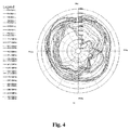
- the radiation pattern of a horizontal plane of the antenna as shown in Fig. 2 is as shown in Fig. 4 .
- the low frequency band of the antenna has the greatest radiation between 270 degrees and 360 degrees of the H surface; when a person holds the terminal with the right hand normally, the spherical surface between 270 degrees and 360 degrees is just in the forward direction close to the face, so that the radiation in this direction is enhanced. In this way, loss of whole 3D radiation can be reduced, which means that the Received Signal Code Powder value of the terminal can be increased, and the signal receiving capacity is improved. As a result, the user experience is improved.
- the RSCP is an index used for evaluating the capacity of a mobile phone for receiving a signal. Under the same radiation intensity of the base station, if the RSCP value displayed by the mobile phone is larger, the capacity of receiving a signal is higher, and the actual use feeling of a user can be enhanced by improving the receiving capacity of the mobile phone under a weak signal scenario. Meanwhile, the RSCP index is also an important reference technical index for some mobile operators to evaluate the radio frequency performance of the terminal at present.
- WCDMA Wideband Code Division Multiple Access
- the RSCP of a Common Pilot Channel should be greater than -95dBm, or the CPICH is deemed to be in weak signal coverage.
- the antenna as shown in Fig. 2 is applied to a mobile phone terminal in the embodiment, and in a microwave anechoic chamber, an actual use scenario of the user is simulated.
- the transmitting power of the base station is simulated to -40dB, and then a comprehensive measurer reads a receiving value, which is the RSCP value, fed back by the mobile phone.
- a comprehensive measurer reads a receiving value, which is the RSCP value, fed back by the mobile phone.
- the RSCP values of the terminal at four angles 0 degree, 90 degrees, 180 degrees and 270 degrees under a free state are tested, and under the state of 180 degrees, the RSCP values of the comprehensive measurer are respectively read by two holding modes.
- the two holding modes are modes that are used by the user at ordinary times. Therefore, the test mode can completely reflect the antenna radiation state of the terminal in an actual use process.
- Table II lists actual test values of the antenna a shown in Fig. 2 of the embodiment, and the main test channel is the WCDMA BAND5 4436 channel.
- Table 2 BS -40dB RSCP(dB) Terminal state 0 degree 90 degrees 180 degrees 270 degrees Free space state -67 -68 -68 -67 Half-holding of the terminal with a hand / / -74.4 / Full-holding of the terminal with a hand / / -70.4 / Average value of two holding states / / -72.4 /
- the general judgment rule is that if the RSCP value in the free space state is -70dB and the RSCP value in the holding state is -75dB, a good state is realized. It can be seen from the above table, the RSCP values of the antenna of the embodiment both in the free space state and the holding state are greater than the judgment standard by 2dB, that is, the receiving performance and the radiation performance of the antenna are higher, and the satisfaction degree of user experience can be enhanced.
Landscapes
- Engineering & Computer Science (AREA)
- Computer Networks & Wireless Communication (AREA)
- Support Of Aerials (AREA)
Applications Claiming Priority (2)
| Application Number | Priority Date | Filing Date | Title |
|---|---|---|---|
| CN201310444354.0A CN104466357A (zh) | 2013-09-23 | 2013-09-23 | 一种天线装置及终端 |
| PCT/CN2014/078044 WO2015039455A1 (fr) | 2013-09-23 | 2014-05-21 | Appareil antenne et terminal |
Publications (2)
| Publication Number | Publication Date |
|---|---|
| EP3051627A1 true EP3051627A1 (fr) | 2016-08-03 |
| EP3051627A4 EP3051627A4 (fr) | 2016-09-28 |
Family
ID=52688163
Family Applications (1)
| Application Number | Title | Priority Date | Filing Date |
|---|---|---|---|
| EP14845756.7A Withdrawn EP3051627A4 (fr) | 2013-09-23 | 2014-05-21 | Appareil antenne et terminal |
Country Status (4)
| Country | Link |
|---|---|
| US (1) | US20160233575A1 (fr) |
| EP (1) | EP3051627A4 (fr) |
| CN (1) | CN104466357A (fr) |
| WO (1) | WO2015039455A1 (fr) |
Families Citing this family (5)
| Publication number | Priority date | Publication date | Assignee | Title |
|---|---|---|---|---|
| CN107317098A (zh) * | 2017-07-21 | 2017-11-03 | 深圳市金立通信设备有限公司 | 一种天线装置和终端 |
| CN107799872A (zh) * | 2017-10-11 | 2018-03-13 | 深圳市同博威科技有限公司 | 一种2.4GHz高效率单模天线 |
| CN109687098B (zh) * | 2018-12-14 | 2020-08-04 | 惠州Tcl移动通信有限公司 | 一种天线和移动终端 |
| CN113241524A (zh) * | 2021-04-16 | 2021-08-10 | 深圳市玛雅通讯设备有限公司 | 一种内嵌于屏幕内部结构的天线、设计方法及其应用 |
| CN115441168A (zh) * | 2022-08-09 | 2022-12-06 | 深圳市飞比电子科技有限公司 | 双频段天线装置及ZigBee模块 |
Family Cites Families (12)
| Publication number | Priority date | Publication date | Assignee | Title |
|---|---|---|---|---|
| AU2003281402A1 (en) * | 2002-07-05 | 2004-01-23 | Taiyo Yuden Co., Ldt. | Dielectric antenna, antenna-mounted substrate, and mobile communication machine having them therein |
| JP2004104419A (ja) * | 2002-09-09 | 2004-04-02 | Hitachi Cable Ltd | 携帯無線機用アンテナ |
| US7990320B2 (en) * | 2005-08-01 | 2011-08-02 | Fractus, S.A. | Antenna with inner spring contact |
| US20080278377A1 (en) * | 2007-05-09 | 2008-11-13 | Vance Scott Ladell | Multi-band antenna |
| CN201112551Y (zh) * | 2007-06-07 | 2008-09-10 | 英华达(上海)电子有限公司 | 一种天线辐射器及天线装置 |
| CN201117812Y (zh) * | 2007-08-02 | 2008-09-17 | 诚实科技香港有限公司 | 多频倒f形天线 |
| CN101471486A (zh) * | 2007-12-24 | 2009-07-01 | 联想(上海)有限公司 | 一种天线 |
| CN201294259Y (zh) * | 2008-07-22 | 2009-08-19 | 比亚迪股份有限公司 | 一种内置双频手机天线 |
| WO2011076080A1 (fr) * | 2009-12-23 | 2011-06-30 | 北京联想软件有限公司 | Terminal mobile |
| CN101777691B (zh) * | 2010-02-23 | 2013-06-19 | 厦门大学 | 开槽印制单极超宽带天线 |
| US20120139794A1 (en) * | 2010-12-03 | 2012-06-07 | Jia-Hung Su | Multi-band antenna |
| CN102694242A (zh) * | 2012-06-08 | 2012-09-26 | 惠州硕贝德无线科技股份有限公司 | 一种全屏幕智能手机3g天线及其设计方法 |
-
2013
- 2013-09-23 CN CN201310444354.0A patent/CN104466357A/zh active Pending
-
2014
- 2014-05-21 EP EP14845756.7A patent/EP3051627A4/fr not_active Withdrawn
- 2014-05-21 WO PCT/CN2014/078044 patent/WO2015039455A1/fr not_active Ceased
- 2014-05-21 US US15/023,754 patent/US20160233575A1/en not_active Abandoned
Also Published As
| Publication number | Publication date |
|---|---|
| CN104466357A (zh) | 2015-03-25 |
| US20160233575A1 (en) | 2016-08-11 |
| WO2015039455A1 (fr) | 2015-03-26 |
| EP3051627A4 (fr) | 2016-09-28 |
Similar Documents
| Publication | Publication Date | Title |
|---|---|---|
| EP3809527A1 (fr) | Dispositif d'antenne et terminal mobile | |
| US9748668B2 (en) | Diversity antenna module and associated method for a user equipment (UE) device | |
| FI104662B (fi) | Antennijärjestely pienikokoisiin radioviestintä-laitteisiin | |
| EP3051627A1 (fr) | Appareil antenne et terminal | |
| US20040121828A1 (en) | Mobile communication | |
| EP2608315A1 (fr) | Appareil d'antenne à diversité commutable et procédés | |
| US9137349B2 (en) | Multi-antenna mobile phone data card and method for reducing specific absorption rate | |
| WO2020125748A1 (fr) | Procédé et appareil d'ajustement dynamique de valeur sar, terminal mobile et support de stockage informatique | |
| US20100033380A1 (en) | Multi-Band Low Profile Antenna With Low Band Differential Mode | |
| EP2747201A1 (fr) | Module d'antenne à large bande multimode et terminal sans fil | |
| EP2991363A1 (fr) | Dispositif de communications sans fil | |
| Ahmad et al. | MIMO antenna system with pattern diversity for sub-6 GHz mobile phone applications | |
| EP4084360A1 (fr) | Système de répétiteur configuré pour ajuster les réglages sur la base de mesures de communication d'équipement d'utilisateur | |
| US9136595B2 (en) | Diversity antenna module and associated method for a user equipment (UE) device | |
| CN103794850A (zh) | 一种小型化低sar值天线 | |
| CN114826292A (zh) | 比吸收率控制方法、控制组件和通信设备 | |
| KR101783609B1 (ko) | 서로 다른 무선통신 방식이 적용된 복수의 무선통신 칩에서 동시에 신호를 전송하기 위한 단말 장치 및 그 단말 장치의 전송 전력 제어 방법 | |
| EP2475153B1 (fr) | System d' antennes en diversité pour dispositif mobile de communication | |
| CN103067548A (zh) | 手机接收差分匹配电路灵敏度的调试系统及方法 | |
| CN114843753B (zh) | 天线装置及其控制方法、电子设备 | |
| Singh | Investigations of MIMO Antenna for Smart Mobile Handsets and Their User Proximity | |
| Anguera et al. | Handset antenna design for FM reception | |
| CN114679196B (zh) | 射频系统及其控制方法、电子设备 | |
| Brown | Dual band two element rim based MIMO antennas with coupling manipulation for low SAR mobile handsets | |
| Yu et al. | A Compact Multi Antenna Design with High Isolation in 5G Full Screen Mobile Phone |
Legal Events
| Date | Code | Title | Description |
|---|---|---|---|
| PUAI | Public reference made under article 153(3) epc to a published international application that has entered the european phase |
Free format text: ORIGINAL CODE: 0009012 |
|
| 17P | Request for examination filed |
Effective date: 20160325 |
|
| AK | Designated contracting states |
Kind code of ref document: A1 Designated state(s): AL AT BE BG CH CY CZ DE DK EE ES FI FR GB GR HR HU IE IS IT LI LT LU LV MC MK MT NL NO PL PT RO RS SE SI SK SM TR |
|
| AX | Request for extension of the european patent |
Extension state: BA ME |
|
| A4 | Supplementary search report drawn up and despatched |
Effective date: 20160829 |
|
| RIC1 | Information provided on ipc code assigned before grant |
Ipc: H01Q 1/36 20060101AFI20160823BHEP Ipc: H01Q 1/24 20060101ALI20160823BHEP Ipc: H01Q 5/371 20150101ALI20160823BHEP Ipc: H01Q 1/48 20060101ALI20160823BHEP Ipc: H01Q 9/42 20060101ALI20160823BHEP |
|
| DAX | Request for extension of the european patent (deleted) | ||
| STAA | Information on the status of an ep patent application or granted ep patent |
Free format text: STATUS: THE APPLICATION HAS BEEN WITHDRAWN |
|
| 18W | Application withdrawn |
Effective date: 20200609 |