EP3052018B1 - Système de tomographie à impédance électrique - Google Patents
Système de tomographie à impédance électrique Download PDFInfo
- Publication number
- EP3052018B1 EP3052018B1 EP14789768.0A EP14789768A EP3052018B1 EP 3052018 B1 EP3052018 B1 EP 3052018B1 EP 14789768 A EP14789768 A EP 14789768A EP 3052018 B1 EP3052018 B1 EP 3052018B1
- Authority
- EP
- European Patent Office
- Prior art keywords
- anatomical
- eit
- models
- data
- patient
- Prior art date
- Legal status (The legal status is an assumption and is not a legal conclusion. Google has not performed a legal analysis and makes no representation as to the accuracy of the status listed.)
- Active
Links
Images





Classifications
-
- A—HUMAN NECESSITIES
- A61—MEDICAL OR VETERINARY SCIENCE; HYGIENE
- A61B—DIAGNOSIS; SURGERY; IDENTIFICATION
- A61B5/00—Measuring for diagnostic purposes; Identification of persons
- A61B5/05—Detecting, measuring or recording for diagnosis by means of electric currents or magnetic fields; Measuring using microwaves or radio waves
- A61B5/053—Measuring electrical impedance or conductance of a portion of the body
- A61B5/0536—Impedance imaging, e.g. by tomography
-
- A—HUMAN NECESSITIES
- A61—MEDICAL OR VETERINARY SCIENCE; HYGIENE
- A61B—DIAGNOSIS; SURGERY; IDENTIFICATION
- A61B5/00—Measuring for diagnostic purposes; Identification of persons
- A61B5/08—Measuring devices for evaluating the respiratory organs
- A61B5/085—Measuring impedance of respiratory organs or lung elasticity
- A61B5/086—Measuring impedance of respiratory organs or lung elasticity by impedance pneumography
-
- A—HUMAN NECESSITIES
- A61—MEDICAL OR VETERINARY SCIENCE; HYGIENE
- A61B—DIAGNOSIS; SURGERY; IDENTIFICATION
- A61B5/00—Measuring for diagnostic purposes; Identification of persons
- A61B5/68—Arrangements of detecting, measuring or recording means, e.g. sensors, in relation to patient
- A61B5/6801—Arrangements of detecting, measuring or recording means, e.g. sensors, in relation to patient specially adapted to be attached to or worn on the body surface
- A61B5/683—Means for maintaining contact with the body
- A61B5/6831—Straps, bands or harnesses
-
- G—PHYSICS
- G09—EDUCATION; CRYPTOGRAPHY; DISPLAY; ADVERTISING; SEALS
- G09B—EDUCATIONAL OR DEMONSTRATION APPLIANCES; APPLIANCES FOR TEACHING, OR COMMUNICATING WITH, THE BLIND, DEAF OR MUTE; MODELS; PLANETARIA; GLOBES; MAPS; DIAGRAMS
- G09B23/00—Models for scientific, medical, or mathematical purposes, e.g. full-sized devices for demonstration purposes
- G09B23/28—Models for scientific, medical, or mathematical purposes, e.g. full-sized devices for demonstration purposes for medicine
- G09B23/30—Anatomical models
-
- A—HUMAN NECESSITIES
- A61—MEDICAL OR VETERINARY SCIENCE; HYGIENE
- A61B—DIAGNOSIS; SURGERY; IDENTIFICATION
- A61B5/00—Measuring for diagnostic purposes; Identification of persons
- A61B5/0033—Features or image-related aspects of imaging apparatus, e.g. for MRI, optical tomography or impedance tomography apparatus; Arrangements of imaging apparatus in a room
- A61B5/0035—Features or image-related aspects of imaging apparatus, e.g. for MRI, optical tomography or impedance tomography apparatus; Arrangements of imaging apparatus in a room adapted for acquisition of images from more than one imaging mode, e.g. combining MRI and optical tomography
-
- A—HUMAN NECESSITIES
- A61—MEDICAL OR VETERINARY SCIENCE; HYGIENE
- A61B—DIAGNOSIS; SURGERY; IDENTIFICATION
- A61B5/00—Measuring for diagnostic purposes; Identification of persons
- A61B5/05—Detecting, measuring or recording for diagnosis by means of electric currents or magnetic fields; Measuring using microwaves or radio waves
- A61B5/053—Measuring electrical impedance or conductance of a portion of the body
- A61B5/0531—Measuring skin impedance
Definitions
- This invention relates to an electrical impedance tomography system according to the preamble of claim 1.
- EIT Electrical impedance tomography
- This technique provides images which represent the distribution of electrical properties within the body, sometimes referred to as heat-maps, in general these images or heat maps have low spatial resolution and the correlation with the actual anatomic structure is unclear. Therefore, EIT-images are usually difficult to interpret.
- EIT Electrical Impedance Tomography
- CT computer tomography
- MRI magnetic resonance imaging
- the electrode belt is attached to the external surface of an individual patient and - due to its fixed physical relationship with the human body - moves together with the patient.
- publication EP 1 000 580 A1 by Ström of 2000 mentions an electrical impedance tomography system for measuring electrical impedances of an internal body section and for representing the measured data by superposing the measured impedance data onto a physical image of the same body section.
- the physical image may be obtained, for example, by computer generation or by using a conventional physical imaging system, such as an x-ray system, a computer aided tomography system, a magnetic resonance imaging system, or an ultrasonic imaging system.
- an EIT image may then be superposed with one of the physical images selected to be closest in position in the relevant physiological cycle to the EIT image.
- the EIT image may be generated cyclically at the frequency of the relevant physiological cycle and the physical image taken at the same point in that cycle. In these ways a more accurate interpretation and correlation of a particular EIT image may be made since both the physical image and the EIT image will reflect substantially the same cyclically induced physical variations in the structure or body region of interest.
- Publication EP 1 000 580 A1 discloses further that the physical images may be stored in a data store prior to the use of the EIT system and may be obtained either from the patient or from another subject, in which case the images represent generic template images of the lungs.
- a microprocessor unit could originate computer generated template images which illustrate the lungs from an algorithm which may have been constructed based on human anatomy and of the location of the belt on the patient.
- the system of Dräger PulmoVista 500 uses one oval-type fixed frame (for all patients) within which the EIT image is projected for presentation of the EIT measurement data.
- a circular or even oval frame into which most commonly the EIT images are projected by an EIT reconstruction algorithm does not produce images which correspond accurately to the anatomy, and is therefore difficult to compare with anatomically accurate images such as from CT or MRI.
- a drawback of any one of above mentioned systems and methods is the lack of a system-intrinsic positioning tool, which allows to align the EIT image with a true reference point or patient anatomy.
- Above mentioned image comparison is a simple display functionality based on superposition or juxtaposition of an EIT image and another physical image originating of a second but different measurement techniques. Relatively good results are achieved only when the patient is positioned accurately during the EIT measurement, i.e. in the exact same position in which the comparative measurement was taken. Moreover, as soon as a test person moves before or during the EIT measurement, the superposed or juxtaposed image will not show the correct reference in any case.
- EP 1 000 580 A1 shows the superposition of the individual X-ray picture of a patient with his EIT images.
- Publication EP 2 624 750 discloses recording of the position of a patient with regard to the gravity vector for further consideration during analysis of the EIT data.
- the sources of ventilation- and cardiac-related activity in the EIT images were localized by an unsupervised method combining statistical and spectral analysis with an image processing algorithm to determine both heart and respiration rate and to define the corresponding heart and lung regions of interest (ROIs).
- This study shows that (a) reconstruction of EIT data on models with correct anatomic boundary shape and (b) detection of heart and lung activity using both spatial and temporal information contained within the EIT data sequence are prerequisites for correct interpretation of EIT data with regard to the functional and anatomical information contained therein.
- Patent application publication US 2004/0006279 A1 discloses a method for generating impedance images of the chest, comprising: acquiring electrical data of the chest; obtaining electrocardiograph data of a patient; analysing the electrocardiograph data to obtain information about breathing parameters at the time the electrical data was acquired; and reconstructing at least one impedance image of the chest from the electrical data and the information about breathing parameters. This method is used to observe the breathing activity.
- the impedance images achieved with this method are similar to or even identical with those created by traditional electrical impedance images with their known limitations such as a lack of anatomical accuracy.
- Patent application publication WO2011/021948 A1 discloses a gastro-electrical activity mapping system and comprising a catheter insertable through a natural orifice into the gastro-intestinal (GI) tract and comprising an array of electrodes for contacting an interior surface of a section of the GI tract to detect electrical potentials at multiple electrodes, and a signal analysis and mapping system arranged to receive and process electrical signals from multiple electrodes of the array and spatially map GI smooth muscle electrical activity as an activation time map, a velocity map, or an amplitude map, which may be in the form of contour plots and may be mapped on an anatomical computer model of at least the section of the GI tract and may be animated.
- the gastro-electrical activity mapping system serves to spatially map and visually display to a user GI electrical activity on an anatomical computer model of at least the section of the GI tract.
- This way of visualizing gastric activity does not create tomographic images as in EIT but merely projects (maps) the measured physiological signals onto their assumed anatomical structure of origin thereby providing users with visual clues intended to facilitate the interpretation of gastric activity.
- Bueno De Camargo ET AL "CONVERTING CT-SCAN IMAGES INTO RESISTIVITY MEASUREMENTS TO FORM AN ANATOMICAL ATLAS FOR ELECTRICAL IMPEDANCE TOMOGRAPHY”,Conference: COBEM 2011 - 21st International Congress of Mechanical Engineering, 24 October 2011 (2011-10-24), pages 1-9 , are relevant to understanding the background of the invention.
- an electrical impedance tomography (EIT) system for determining electric properties of an internal body section of a patient (11) comprising
- EIT image is understood to be the representation of the (changes in) conductivity distribution in the body.
- derivative images can be created at ease by processing such EIT images to display e.g. tidal volume (as mentioned above), signal power at different frequencies or other information derived from EIT image (many examples in literature - inflection points, delay indices, etc).
- EIT image any such distribution may be referred to as "EIT image”.
- the anatomical models are preferably three dimensional, thus 3D anatomical models.
- the anatomical models, in particular the 3D anatomical models are based on a statistical description of the population, thus statistics based anatomical models.
- the 3D anatomical models used for reconstructions work under the assumption that the imaged body is immutable along its vertical axis (extrusion).
- herein presented models are realistic anatomical representations of the true 3D structure of the human thorax.
- the model used to reconstruct the image of an individual monitored by EIT according to present invention does not have to be this individual's truly personalized model but one that can be chosen from a pool of models using biometric data of the patient monitored by EIT.
- a key feature of the system of present invention is the use of a chosen anatomical model for reconstructing an EIT image.
- the anatomical model is either 1) embedded in the reconstruction algorithm, if the algorithm has the form of a stored reconstruction matrix 2) stored and used by the reconstruction algorithm, 3) generated on the fly and used by the reconstruction algorithm.
- the model is generated on account of biometric data of the specific patient and a statistical description of thorax shape in the population.
- such model can be generated for any combination of biometric data.
- Biometric data (201) comprise e.g. parameters such as gender, age, race, and easy-to-obtain measurements of anatomic characteristics such as e.g. weight, height, arm span and thoracic circumference.
- biometric data (201) comprise at least body weight and body height and optionally gender and/or age and/or thoracic circumference.
- biometric information about the thoracic circumference (either in total or half the circumference mid spine to mid sternum multiplied by a factor of 2) obtained by a simple tailor measurement tape might further improve both: 1) the selection of the model and 2) the choice of the most appropriate size of the sensor belt for an individual patient.
- the position (203) of individual electrodes of the electrode array (13) is accounted for by the anatomical model (204), in particular in that the input interface allows input of or is adapted to read electrode array characteristics and position on an individual patient.
- the anatomical model contains information about the position of the electrodes on the individual patient. Although the body (anatomy) does not change if the belt is moved, the position, size and spacing of the electrodes is critical for the success of EIT image reconstruction.
- the anatomical model representing the 3D structure of the thorax presented herein does account for these parameters.
- the characteristics of the belt may be pre-defined, without losing accuracy, if the belt is designed to have a specific and defied position with respect to the anatomy when correctly donned, in which case input or read-out of electrode array characteristics is not required.
- the electrode array (13) is selectable from several different sizes in order to account for anatomical constitution, e.g. ranging from slim to obese.
- the system comprises a belt carrying the electrode array (13), preferably the electrodes of the array being aligned in a spaced apart relationship and spread from a first belt end to a second belt end.
- the system can deal with fixed distances (i.e. equidistant spacing) between electrodes as is the case in non-elastic EIT belts as well as with distances changing with breathing in elastic belts.
- Electrodes on a belt as opposed to free individual electrodes, fixes their relative positions.
- Belt types (such as e.g. disclosed in WO2013/110207 ) preferably used in connection with the system according to the present invention) remain in a specific and defined relationship to the anatomy. Both of these features ease the modeling task, because the electrode positions and orientations can be assumed to be known a priori. Were this not the case, laborious procedures for placing the electrodes with respect to specific anatomical landmarks would need to be in place (nearly impossible), or another system (e.g. imaging) would need to be employed to determine electrode positions.
- the belt carries an identifier, such e.g. a radio frequency identification (RFID), which is readable by the data processor.
- RFID radio frequency identification
- the identifier carries information about the number of electrodes contained in the electrode array and optionally the length of the array and/or the distance between neighboring electrodes. This information may be used in generating the anatomical model, in particular the 3D anatomical model, and is relevant to processing the data originated by the electrode array, and hence EIT image reconstruction.
- the information contained within the identifier such as belt length
- the user entered biometric data such as e.g. the thoracic circumference
- an estimate of the quality of the fit between the patient's body and the belt size may be estimate.
- the belt may be detected as fitting perfectly, or being too long, or too short, for a given patient. This information can then be used in generating the anatomical model to improve the correspondence between electrode placement on the patient and the model.
- the distances between neighboring electrodes of the electrode array (13) are predetermined, preferably the distances between the electrodes of the electrode array (13) are the same or the higher distance values are a multiple of the lower distance values.
- the reconstruction algorithm is adapted to take account of the number and position of electrodes comprised in the electrode array. Moreover, the reconstruction algorithm is adapted to take account of the number of electrodes actually in contact with the subject's body.
- the positions of the electrodes as far as the algorithm is concerned are fixed by the anatomical model, in particular the 3D anatomical model (unless the algorithm modifies the anatomical model, in particular the 3D anatomical model).
- the reconstruction algorithm is adapted to take account of the number of electrodes comprised on the electrode array, in that, when the belt is mounted on a patient, in a situation where two electrodes of each end of the belt overlap each other, for the purpose of the reconstructions at least one of the two overlapping electrodes is considered to be mute, i.e. electrically disconnected.
- the system according to present invention further can comprise a sensor for determining the orientation of the EIT measurement plane with respect to the gravity vector, in particular for determining the spatial orientation of the body section of the patient.
- a sensor device like the one disclosed in publication EP 2 624 750 may be used.
- the orientation will change with any change of the patient's body position as the electrodes are attached to the patient's body.
- the herein presented new system allows for presentation of the EIT data with regard to the gravity vector.
- the electrode array (13), preferably the belt, carriers the sensor for determining the orientation.
- the data processor (19) is adapted to use position data as input for a display algorithm in order to display patient position.
- the processor is adapted to display the representation in alignment with the gravity vector and/or in respect to an indicator of the gravity vector, so that the position of patient at the time of measurement is apparent from the display.
- the data processor (19) is adapted to output a cross-section image (107) of the anatomical model in the plane of EIT measurement.
- the cross-section image comprises contours of the external body and internal organs.
- the contours delineating organs advantageously are overlayed on (i.e. overlay) the EIT image.
- the cross-section image or rather these contours are derived from the anatomical model (i.e. representing the outer boundaries of the modeled organs within the electrode plane), and hence from a mathematical description in terms of biometrics, rather than a segmentation of the specific patient's anatomical imaging, such as CT- or MRI-slices or scans.
- the cross-section image (207) shows expected thorax and organ contours in the measurement plane.
- ROI Regions Of Interest
- the processor (19) is adapted to generate for display a superposed combination of the representation (208) and the cross-section image (207) of the anatomical model.
- the manner of this superposition is defined, iccording to the invention, in claim 1.
- electrode positions can be superposed onto the representation, i.e. on the EIT image.
- the contours can be used to group pixels of the representation (i.e. EIT image) based on which contour they fall in and optionally the various metrics (such as e.g. amplitude of change or time course display) are calculated for each group of pixels.
- the areas within the contours are called "Regions Of Interest".
- pixels falling within a respective contour comprise or define (anatomically-related) ROIs.
- the representation (208) is an image or matrix of the distribution of the electrical properties, preferably adapted for display in form of a heat map, whereby the values of the matrix are turned into a heat map.
- Heat-maps are derived by processing series of one or more EIT images of the same patient.
- a heat-map does not represent a physical object but rather "states" of a physical object, here e.g. the functional state of the breathing lungs.
- Function or action is not anatomy (or morphology).
- a heat map only makes sense, if the underlying structure, i.e. in particular the anatomical structure, is known. While conventional EIT monitors lung action or function, it remains uncertain where in the thorax exactly the action happens.
- the new system according to present invention provides an anatomical reference for the measured EIT data, so that action (or function) and anatomy can be linked.
- the new system according to present invention links EIT data pixels to a mathematical mesh point of the anatomical model.
- the system of present invention brings changes of electric property (as a reflection of organ function) and anatomy of said organ together.
- the system according to present invention allows to display lung function in a lung model at accurate location; such display may be called heat-map.
- the storage unit (21) comprises information for providing the plurality of anatomical models for use by the data processor (19) for reconstruction, wherein the information is provided e.g. in a library (25) or within an algorithm such as e.g. the reconstruction algorithm (23).
- the processor is adapted to generate or recall from storage the plurality of anatomical models (204) on account of biometric data of an individual patient (201) and of biometric data of a population (102).
- the key link here is that the biometric data of the individual patient are used to select from a representative cohort of patients (to which this patient should belong) the model matching best. Therefore, the choice of the population is essential and precludes use of the inventive methods in cases in which the patient does not belong to such population (i.e. for children another set of models must be used which is generated i.e. for each age group and gender separately). For example in a tested population of adult Caucasians (adults from central Europe), age did not seem to be a key factor influencing the modeling. Therefore it was possible to simplify the system, by removing the parameter age from the set of biometric data needed for the selection process. This is advantageous since it eliminates the need for additional sets of age-specific anatomical models. In the tested adult population "one age fits all". However this finding is not necessarily true in children or other populations or races such as Asians, Africans etc.
- the processor is adapted to generate the plurality of anatomical models (204) on account of a statistical description of the population and information on the individual patient and information on the electrodes.
- the statistical description of the population comes from CT, MRI or equivalent data and biometric data.
- the processor is adapted to generate the plurality of anatomical models (204) on account of
- the idea is to cover the widest possible range of patients with one set of anatomical models, in particular 3D anatomical models, and only adapt this set of models if it no longer becomes representative of the individuals of the underlying population from which it was generated.
- it can be advantageous to limit the population to a specific age group of children and/or a specific race or other criteria, in order to customize the anatomical model and therewith the system of present invention for a specific user group (i.e. patient group).
- the "standardized ribcage” is meant to represent a rectangle of defined proportions, the specific proportions being irrelevant, into which organ contours segmented from transverse images from an anatomically accurate medical imaging modality are fitted prior to calculating their average by independently scaling their width and height such that they equal those of the rectangle. This is further described in the paragraph “Data processing” and the associate Fig. 2 below.
- the mathematical relationships (111) account for biometric data (102) of a population and anatomical data (101), e.g. CT-scan data, of a population, in particular the same population. For every patient in the dataset of the scan that form a sample of the population, both biometric data and CT data are required.
- the organ shapes of a standardized ribcages (108) originate from anatomical data (101), e.g. CT-scan data.
- the processor (19) is adapted to use a lookup table (202) to select an anatomical model, the lookup table (202) comprising
- the lookup table is one way in which a particular anatomical model may be chosen for a particular patient.
- Separate exemplary cross-section contour models may be used for different gender and/or different age groups.
- the processor (19) selects a model on account of the biometric data (201) of an individual patient.
- the processor (19) is adapted to select from at least two gender specific lookup tables (202).
- the lookup tables may be age-specific and/or race-specific and/or specific with respect to other features, preferably in combination with the mentioned gender specificity.
- the exemplary cross-section contour models can range from a slim type to an obese type, preferably at least for a constant body height.
- a means for providing anatomical data can comprises any one of x-ray computed tomography systems, magnetic resonance imaging systems, or any other imaging modality capable of providing anatomically accurate cross-sections of the human body.
- present inventive system allows to monitor and map the functional status of a breathing lung.
- State of the art EIT imaging reveals changes in the lung of a breathing patient, however a correct link to the morphological location of action is not possible.
- present invention provides a link between the morphology and the activity of an organ such as e.g. the lung or heart.
- present invention provides the reference from an anatomical model (in particular a 3D anatomical model), i.e. a mathematical mesh, as well as from a display point of view. Meaning that, firstly, the EIT image has the shape of the thorax and, secondly, the organ contours are overlain onto the image to aid interpretation.
- Present invention uses data from another imaging technique than EIT, here in particular CT (computer tomography), in order to establish a means of generating models representing the inner conductivity of a body section in 3D for individual patients. These models are used to calculate the EIT images.
- CT computer tomography
- the organ contours which are separately derived from the same 3D models
- present inventive system allows for annotation of the EIT image in order to indicate to a user what is (supposed to be) where. This method is fundamentally different from the conventional way of visually comparing an EIT image with a reference image, irrespective of whether the reference image is a picture of the relevant patient or a standardized template.
- the EIT system according to present invention opens up new fields of application for the EIT technology. Situations in which gravity is a relevant factor, for diagnosis and eventually also for therapy the effects of gravitation must be taken into account. With present new EIT system this becomes possible because now it is possible to represent EIT results with respect to true body orientation and position.
- Fig. 1 an electrical impedance tomography (EIT) system according to present invention is presented.
- the system comprises an electrode array, which is locatable in electrical contact with the skin surface of a patient 11.
- the electrode array is attached to a belt 13, which is positioned around the patient's thorax.
- the system further comprises an instrument 15 for applying voltage or current to two or more of the electrodes of the electrode array and for measuring voltage or current between pairs of electrodes of the electrode array.
- instrument 15 stimulates the patient's body with current (or, equivalently, with voltage), and measures voltage (e.g. potential differences between pairs of electrodes or between individual electrodes and the ground).
- the measured signals are transmitted to the computing unit 17, which comprises a processor 19 and a storage unit 21.
- the processor 19 uses the measured voltages, an anatomical model (i.e. a model of the body), and a model of the physics to reconstruct an image of the conductivity (or admitivity) distribution within the patient's body section circumvented by the belt 13. Although that image is most often presented as 2D raster (pixel-based) image, it could in principle be three-dimensional.
- image reconstruction is understood as a method to calculate (recover, i.e. reconstruct) electrical properties (or changes thereof) inside a volume from (electrical) data acquired at its surface.
- the storage unit 21 comprises at least one reconstruction algorithm 23.
- the reconstruction algorithm 23 is used by the data processor 19 for processing the measured electrical voltages of the examined body section into electrical conductivities by reconstructing the measured electrical voltages onto a section of the anatomical model.
- One or several anatomical models may be part of the algorithm (i.e. embedded in the algorithm) or stored in the storage unit 21, e.g. preferably as a library 25 of a set of anatomical models.
- the anatomical models are descriptive of the three dimensional body section as well as electrode placement on it. In particular, described are external body shape, e.g. thorax, and organ shapes, e.g. lungs and heart, as well as the mutual arrangement of these shapes.
- the plurality of anatomical models comprises a set of standardized anatomical body section models of the thorax.
- the different models of the plurality of anatomical models are distinguished from each other by their anatomical composition and shapes and/or the electrode characteristics (spacing, size, number, position, orientation, etc.).
- the anatomical model is e.g. a model of a thorax.
- a 3D model in the form of a tetrahedral mesh is used.
- the anatomical model is enhanced by linking mesh element to physical properties, such that each mesh element is linked to a conductivity value.
- there might be foreseen several libraries (25) which are limited to a combination of gender, age, race and/or other relevant biometric parameter.
- the storage unit 21 comprises a lookup table 27.
- lookup table may comprise a pool of preset biometric data to choose from, corresponding to the anatomical models stored on the device.
- Anatomical composition means the mutual position of organ contours and external body contour.
- the anatomical composition comprises the mutual position of lung, heart and thoracic contours.
- Anatomical shapes means the shapes of organ contours and the shape of the external body contour.
- the anatomical shapes comprise the shape of the lung contour, the shape of the heart contour and the shape of the thorax contour.
- further organs may be taken into account, such as e.g. ribs or aorta.
- the anatomical model of the body is a discretization of the imaged volume of the body into finite elements (here: tetrahedral), each associated with a function (here: constant) describing the distribution of conductivity within that element. Internal boundaries within the volume (such as between organs) are mirrored in the model in that no finite element crosses an internal boundary.
- the system comprises an input interface 29 for inputting biometric data of the patient.
- the biometric data of the patient are used by the data processor 19 to select the anatomical model from the plurality of anatomical models stored in the data base 25, which describes the thorax of the patient best.
- a thoracic cross-section which corresponds to the body plane circumvented by the electrode array belt is displayed on a displaying means 31, e.g. on a monitor.
- This thoracic cross-section is computed on account of the anatomic model.
- a representation of the reconstructed (changes in) electrical conductivities is displayed on the displaying means 31.
- the cross-section and the representation are combined into a superposition. The manner of this superposition is defined, according to the invention, in claim 1.
- the system according to present invention serves to determine and present electrical property distribution, or change thereof, of an internal body section of a patient 1.
- Image reconstruction technique is applied in order to compute the distribution.
- EIT electrical impedance tomography
- Data consists of a) transversal tomographic slices of a sample of patients (i.e. CT, MRI or EBCT or any future modality that can do so), spanning a wide range of ages, bodily structures and body mass index (BMI) values, where a small number of slices crossing different vertebrae for each patient are segmented; and b) longitudinal slices showing the spine of a possibly different population of patients.
- a transversal tomographic slices of a sample of patients i.e. CT, MRI or EBCT or any future modality that can do so
- BMI body mass index
- the contours of the organs are scaled such as to fit in a common bounding box (dashed inner rectangle circumscribing the lungs and heart in Fig. 3 ) and grouped according to the vertebra intersected by the originating slice. Sets of average organ contours, one per vertebra, are calculated.
- the outer thorax shape varies widely in humans, and because this shape has a very strong influence on the quality of EIT images, it does not make sense to describe the thorax as an average shape in the same way as the inner organs. Instead, a more flexible parametric description is required. The challenge is, however, to develop a description with few parameters that can be estimated from the available data, while striking a balance between goodness of fit and generalizability.
- the thorax contour is described as a closed rational Bezier spline, that is a series of curved segments described by two end-points and one or more control points, not generally lying on the segment, which control its curvature.
- the thorax contour is defined as four spline segments ( Fig. 3 ).
- the segments' endpoints are divided by the dorso-ventral axis passing through the vertebra center and a perpendicular horizontal (left-right) axis at the level where the thorax is the widest.
- each segment describes one thorax "quadrant".
- the thorax is assumed to be left-right symmetric, only two quadrants need to be defined (e.g. top-right and bottom-right).
- the bottom quadrants are defined by a quadratic spline with one control point b1, located at the corner of the thorax bounding box.
- the endpoints have a fixed weight of 1, whereas the weight of the control point is variable.
- the top quadrants are defined by three control points (4 th degree spline).
- the first control point t1 is located on the ventral side of the thorax bounding box at a distance away from the sternum equal to half the average width of the ribcage and thorax bounding boxes.
- the second control point t2 is inside the ribcage bounding box. Vertically, it is located at the midline of the ribcage bounding box; horizontally, it is removed from the side of the bounding box by the distance between the sternum and the ventral side of the thorax bounding box.
- This formula is designed to place the control point below the line defined by the ventral side of the ribcage bounding box.
- the weights for both endpoints and the last control point are 1; the weight of the first control point is 1.5, while the weight of the middle control point t2 is variable.
- the parametric contour descriptions are fitted to the segmented thorax contours by setting the point locations according to their definitions and adjusting the variable weights of control points b1 and t2 such as to achieve the best possible fit, i.e. minimize the non-overlap area.
- weights are added to the data set for statistical analysis.
- a set of measurements is extracted, described in the next section. These are used as dependent variables in a series of ordinary linear regression models. In each model, predicting one measurement, the independent variables are selected from: other extracted measurements, vertebra level of the slice, and the patient's biometric data: age, gender, height, weight and BMI. Additional independent variables are created by linear combinations and squares of those listed.
- Machine learning methods other than ordinary least squares regression could be used just as well.
- the type of model used has no bearing on the process.
- the 3D anatomical models are tetrahedral finite element models (FEMs) of the thorax between vertebrae T3 (3 rd thoracic vertebra) and L1 (1 st lumbar vertebra), including internal organs.
- FEMs finite element models
- the height of the model in caudal-cranial extension is calculated by summing the predicted heights of the vertebrae.
- Horizontal cross-sections of the model at the heights of vertebra centers correspond to the respective approximate slices created using the above procedure, as in Fig. 4 .
- electrodes are included at the surface of the model with local FEM refinement for better simulation accuracy when used as the forward model in an EIT reconstruction algorithm, see Fig. 5 .
- a number of 3D models for a plurality of pre-set combinations of biometric data are stored on the device.
- An appropriate model for a given patient is then chosen from a lookup table 202 ( Fig. 11 ) based on the given patient's biometric data and the available models. The following describes the creation of such a lookup table.
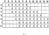
- FIG. 6 body weight (in kg, horizontal axis) is plotted against body height (in m, vertical axis) and the resulting BMI (weight in kg divided by height in meters) is shown as number in the table grid at the appropriate position.
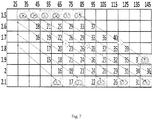
- Fig. 7 the same table is presented including graphics of simulated approximated cross-sections as per Fig. 2 generated as described above for some selected extreme combinations of body height and body weight.
- the simulated thoracic cross-sections result from CT investigations of a plurality of persons, as described above, and were generated based on the regression calculations described in the text (see above paragraphs "Statistical analysis” and “Building an approximate slice”) using subject body height, body weight (the gender is male, and age fixed at 45 years).
- the simulated thoracic cross-sections (and hence also the 3D anatomical models that may be built from them) of extreme small body height usually can be extrapolated to a simulated thoracic cross-sections of extreme large body height, whereby the corresponding simulated thoracic cross-sections have the same proportions as their small counterpart.
- extreme cross sections of very small and very tall types match in their shapes and contour arrangement.
- Fig. 7 the extreme simulated thoracic cross-section counterparts of small and large body height are graphically connected via the dotted lines of the double arrows.
- surprisingly simulated thoracic cross-sections of intermediate body height match in their size relationship with the extremes under the same dotted line, see Fig. 7 .
- the dotted lines connect cross-sections that are essentially equivalent.
- the connected cross-sections differ merely in their absolute sizes, however not in the relative arrangement of the organ contours.
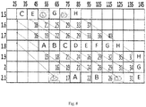
- FIG. 8 suggests, by way of example, 8 base thoracic 3D models, A to H, represented by their corresponding simulated cross-section slices.
- each body-mass index square is assigned to one particular organ shape called A through H. This makes 8 categories of organ shapes.
- Each category A through H is then assigned to the other squares above and below the centre-line, by following the dotted lines, as shown in Fig. 8 .
- a library containing few base types of thoracic 3D models e.g. A to H of Fig. 8
- an algorithm with an empirical rule for scaling said base models up and down suffices in order to match most of the population's individuals based on simple biometric data, including body height, body weight and optionally the gender and/or age.
- a library or lookup table 202 comprising few base type 3D models can be kept small and therefore needs little storage space. For example using 3 to 15, preferably 5 to 12, most preferred about 8, basic thoracic 3D models from which one is selected based on a patient's biometric data. Above refers to adults. For children, the library had to be extended for different age groups.
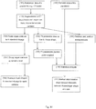
- Fig 10 is summarized the process of creating standardized average organ shapes for each vertebra of a thorax and mathematical relationships between biometric data and body and organ shapes and sizes based on a study of the thorax shape and size in a population.
- CT data of a population 101 are segmented 102: in the transverse plane organ contours are outlined (as in Fig. 2 ); in the sagittal plane intervertebral disk centers are marked 103. From those, various distance and position measurements 106 are extracted (those shown in Fig 2 plus disk-to-disk distances). Separately, organ contours are scaled to fit a standard ribcage size 104, grouped by the vertebra the originating transverse slice intersects 107, and average organ shapes are calculated 108, one per vertebra. (Paragraph: “Data processing”). "Shape" refers to a cross-section plane.
- Standard means that each set of organ contours originating from segmentation of the CT data is scaled to fit a rectangle (bounding box) of the same specific size X times Y.
- Average refers to shape averaging, once all shapes are scaled to the same rectangle.
- a parametric (spline) description of a thorax shape is fitted to the segmented thorax contour in each transverse slice 105 in each patient, resulting in a set of control point weights 109 (Paragraph: "Parametric description of thorax shape").
- the extracted distance measurements 106 and shape descriptors 109 are related to the biometric data 102 by statistical modeling 110 (for example using ordinary least square regression), resulting in a set of mathematical formulae 111, one per measurement/ descriptor, allowing the prediction of the measurement/ descriptor based on biometric data.
- Fig. 11 is summarized the operation of the system of present invention.
- the stored average organ shapes 108 and mathematical relationships between biometric data 111 are used together with biometric data of an individual patient 201 and information about the electrode belt placement and characteristics 203 to generate an individualized 3D anatomical model of the thorax ( Fig. 5 ) (Paragraph: "3D Models").
- the patient's true biometric data may be approximated to the closest available value using a lookup table (as in Fig. 7 and 8 ). In that case, the models (now limited in number by the lookup table) may be stored rather than built on the device.
- the total number of permissible height/ weight/ gender combinations is predetermined. That means that rather than build a model specifically for e.g. a 178.3 cm, 86.4 kg male, a model for 175cm, 85kg male which is stored on the device is used.
- the 3D model 204 is used to reconstruct 206 measured EIT data 205 into an EIT image 208.
- the reconstruction process involves a multiplication by a so called Reconstruction Matrix (RM) which is calculated based on the 3D model. If this is the case, and if a lookup table is used to limit the number of the 3D models, then the number of RMs is also limited and so may be stored on the device. This obviates the need to store the 3D models on the device.
- RM Reconstruction Matrix
- a cross-section of the 3D model along the plane defined by the electrode belt is calculated, which defines the expected organ contours in the EIT image 207.
- Those contours are overlaid on the image 209 and may also be used to group pixels of the EIT image according to the organ they fall into for analysis.
- the expected contours 207 must be stored on the system.
- the superposition 209 may be displayed on a graphical user interface 213. If orientation and/or position of the patient 211 during EIT measurement is known, e.g. due to determination of the orientation and position of the patient (or the electrode belt) with regard to the gravity vector, the display 213 may indicate such orientation and position.
- EIT data measurement and evaluation on a particular patient comprising the steps of:
- the EIT images on display are mathematically correctly reconstructed and thus specific for an individual patient, they are displayed in correct proportions and preferably in a correct relation to the gravity vector.
Landscapes
- Health & Medical Sciences (AREA)
- Life Sciences & Earth Sciences (AREA)
- Engineering & Computer Science (AREA)
- Physics & Mathematics (AREA)
- General Health & Medical Sciences (AREA)
- Medical Informatics (AREA)
- Veterinary Medicine (AREA)
- Biomedical Technology (AREA)
- Heart & Thoracic Surgery (AREA)
- Biophysics (AREA)
- Molecular Biology (AREA)
- Surgery (AREA)
- Animal Behavior & Ethology (AREA)
- Public Health (AREA)
- Pathology (AREA)
- Nuclear Medicine, Radiotherapy & Molecular Imaging (AREA)
- General Physics & Mathematics (AREA)
- Pulmonology (AREA)
- Radiology & Medical Imaging (AREA)
- Educational Technology (AREA)
- Business, Economics & Management (AREA)
- Algebra (AREA)
- Mathematical Analysis (AREA)
- Mathematical Optimization (AREA)
- Mathematical Physics (AREA)
- Pure & Applied Mathematics (AREA)
- Computational Mathematics (AREA)
- Educational Administration (AREA)
- Medicinal Chemistry (AREA)
- Theoretical Computer Science (AREA)
- Chemical & Material Sciences (AREA)
- Physiology (AREA)
- Measurement And Recording Of Electrical Phenomena And Electrical Characteristics Of The Living Body (AREA)
- Apparatus For Radiation Diagnosis (AREA)
- Dermatology (AREA)
Claims (17)
- Système de tomographie par impédance électrique (EIT) destiné à déterminer des propriétés électriques d'une partie corporelle interne d'un patient (11) comprenant- un réseau d'électrodes (13) positionnable en contact électrique avec le corps d'un patient ;- un dispositif (15) pour appliquer un courant ou une tension électriques entre au moins deux électrodes du réseau d'électrodes (13) et pour mesurer des tensions et/ou courants électriques générés entre d'autres combinaisons de paires du réseau d'électrodes (13) ;- une unité informatique comprenant un processeur de données (19) et une unité de stockage (21),- l'unité de stockage (21) comprenant au moins un algorithme de reconstruction pour utilisation par le processeur de données (19) pour reconstruire les tensions électriques mesurées de la partie corporelle en propriétés électriques ou changements de propriétés électriques,- le processeur de données étant adapté pour délivrer une représentation des propriétés électriques reconstruites, c.-à-d. une image EIT, et- le processeur de données (19) étant adapté pour générer et/ou traiter une pluralité de modèles anatomiques (204) descriptifs de la partie corporelle,- le système comprenant une interface d'entrée (29) pour entrer des données biométriques (201) du patient pour utilisation par le processeur de données (19),- le processeur de données (19) étant adapté pour sélectionner un des modèles parmi la pluralité de modèles anatomiques en prenant en compte les données biométriques du patient,- le processeur de données (19) étant adapté pour utiliser le modèle sélectionné de la pluralité de modèles anatomiques pour reconstruire les tensions électriques mesurées de la partie corporelle en propriétés électriques ou changements de propriétés électriques, le modèle anatomique étant un modèle anatomique basé sur des statistiques et étant basé sur une description statistique d'une population,- le processeur de données (19) étant adapté pour délivrer une image en coupe transversale (207), comprenant des contours du corps externe et d'organes internes, du modèle anatomique dans le plan de mesure EIT, et le processeur (19) étant adapté pour générer pour affichage une combinaison superposée (209) de la représentation (208), c.-à-d. l'image EIT, sur l'image en coupe transversale (207) du modèle anatomique.
- Système selon la revendication 1, dans lequel le processeur (19) est adapté pour- sélectionner un modèle anatomique à partir de quelques types de base de modèles thoraciques 3D ayant différentes formes d'organe et- utiliser un algorithme pour agrandir ou réduire lesdits modèles types de base, de telle sorte que des coupes transversales d'un modèle agrandi ou réduit diffèrent de la coupe transversale respective de son modèle type de base principalement par leur taille absolue, mais cependant pas par la forme des organes et/ou l'agencement relatif des contours des organes.
- Système selon la revendication 1 ou 2, dans lequel les données biométriques (201) prises en compte sont au moins un poids corporel et une hauteur corporelle.
- Système selon l'une quelconque des revendications précédentes, caractérisé en ce que les données biométriques (201) comprennent en outre un sexe et/ou un âge et/ou une circonférence thoracique.
- Système selon l'une quelconque des revendications précédentes, caractérisé en ce que la position (203) d'électrodes individuelles du réseau d'électrodes (13) sont prises en compte pour le modèle anatomique (204), en particulier en ce que l'interface d'entrée permet l'entrée de ou est adaptée pour lire des caractéristiques et une position du réseau d'électrodes sur un patient individuel.
- Système selon l'une quelconque des revendications précédentes, caractérisé en ce que le réseau d'électrodes (13) est sélectionnable parmi plusieurs tailles différentes afin de prendre en compte la constitution anatomique, par ex. allant de mince à obèse.
- Système selon l'une quelconque des revendications précédentes, caractérisé en ce que les contours sont utilisés pour regrouper des pixels de la représentation (c.-à-d. l'image EIT) sur la base du contour dans lequel ils se situent et, éventuellement, les diverses métriques (telles que, par ex., l'amplitude du changement ou l'affichage du décours temporel) sont calculées pour chaque groupe de pixels.
- Système selon l'une quelconque des revendications précédentes, caractérisé en ce que le processeur est adapté pour générer ou rappeler depuis l'unité de stockage la pluralité de modèles anatomiques (204) en prenant en compte des données biométriques d'un patient individuel (201) et des données biométriques d'une population (102).
- Système selon l'une quelconque des revendications précédentes, caractérisé en ce que le processeur est adapté pour générer la pluralité de modèles anatomiques (204) en prenant en compte- une description statistique de la population, qui provient de préférence de données de TDM, IRM, ou d'autres données équivalentes, et de données biométriques,- des informations sur le patient individuel, et- des informations sur les électrodes.
- Système selon l'une quelconque des revendications précédentes, caractérisé en ce que le processeur est adapté pour générer la pluralité de modèles anatomiques (204) en prenant en compte- des formes de corps et d'organe d'une pluralité de cages thoraciques normalisées (108), et des relations mathématiques (111) décrivant des relations statistiques entre des données biométriques (102) et des formes de corps et d'organe d'une population.
- Système selon la revendication 8 précédente, caractérisé en ce que les relations mathématiques (111) prennent en compte des données biométriques (102) d'une population et des données anatomiques (101), par ex. des données de tomodensitogrammes, d'une population, en particulier de la même population.
- Système selon l'une quelconque des revendications précédentes, caractérisé en ce que le processeur (19) est adapté pour utiliser une table de recherche (202) pour sélectionner un modèle anatomique, la table de recherche (202) comprenant- des modèles de contour en coupe transversale exemplaires pour certaines combinaisons de hauteur corporelle et de poids corporel, de préférence pour une hauteur corporelle constante,- une règle pour l'indication de chemins entre diverses coordonnées de hauteur corporelle et de poids corporel reliant les coordonnées relatives à des contours en coupe transversale de proportions dimensionnelles supposées constantes empiriquement.
- Système selon la revendication 12 précédente, caractérisé en ce que le processeur (19) effectue une sélection en prenant en compte les données biométriques (201) d'un patient individuel.
- Système selon l'une quelconque des revendications 12 et 13 précédentes, caractérisé en ce que le processeur (19) est adapté pour effectuer une sélection à partir d'au moins deux tables de recherche spécifiques du sexe, spécifiques de l'âge et/ou spécifiques de la race (202).
- Système selon l'une quelconque des revendications 12 à 14 précédentes, caractérisé en ce que les modèles de contour en coupe transversale exemplaires vont d'un type mince à un type obèse, de préférence au moins pour une hauteur corporelle constante.
- Système selon l'une quelconque des revendications précédentes caractérisé en ce que les moyens pour obtenir des données anatomiques comprennent n'importe quel élément parmi les systèmes de tomodensitométrie par rayons X, les systèmes d'imagerie par résonance magnétique, ou toute autre modalité d'imagerie pouvant fournir des coupes transversales anatomiquement précises du corps humain.
- Système selon l'une quelconque des revendications précédentes, caractérisé en ce que le processeur est adapté pour afficher la représentation en alignement avec le vecteur gravité et/ou par rapport à un indicateur du vecteur gravité.
Applications Claiming Priority (2)
| Application Number | Priority Date | Filing Date | Title |
|---|---|---|---|
| CH17102013 | 2013-10-04 | ||
| PCT/CH2014/000143 WO2015048917A1 (fr) | 2013-10-04 | 2014-10-03 | Système de tomographie à impédance électrique |
Publications (2)
| Publication Number | Publication Date |
|---|---|
| EP3052018A1 EP3052018A1 (fr) | 2016-08-10 |
| EP3052018B1 true EP3052018B1 (fr) | 2020-04-15 |
Family
ID=50382156
Family Applications (1)
| Application Number | Title | Priority Date | Filing Date |
|---|---|---|---|
| EP14789768.0A Active EP3052018B1 (fr) | 2013-10-04 | 2014-10-03 | Système de tomographie à impédance électrique |
Country Status (3)
| Country | Link |
|---|---|
| US (1) | US10952634B2 (fr) |
| EP (1) | EP3052018B1 (fr) |
| WO (1) | WO2015048917A1 (fr) |
Families Citing this family (30)
| Publication number | Priority date | Publication date | Assignee | Title |
|---|---|---|---|---|
| JP6218569B2 (ja) * | 2012-11-22 | 2017-10-25 | 東芝メディカルシステムズ株式会社 | 磁気共鳴イメージング装置 |
| CN106232002B (zh) * | 2014-04-16 | 2019-09-03 | 皇家飞利浦有限公司 | 具有增强的稳定性和速度的电导率重建的ept方法 |
| CN107209794B (zh) * | 2015-01-28 | 2022-02-08 | 皇家飞利浦有限公司 | 解剖结构的有限元建模 |
| WO2018085951A1 (fr) * | 2016-11-11 | 2018-05-17 | Swisstom Ag | Ceinture de détection et aide au positionnement pour l'imagerie de tomographie par impédance électrique chez les nouveau-nés |
| DE102016014252B4 (de) | 2016-11-30 | 2023-02-02 | Drägerwerk AG & Co. KGaA | Vorrichtung und Verfahren zur Bestimmung einer Umfangsform einer Elektrodenanordnung zur Elektro-Impedanz-Tomographie |
| DE102016014251B4 (de) | 2016-11-30 | 2023-02-02 | Drägerwerk AG & Co. KGaA | Vorrichtung und Verfahren zur Ermittlung einer axialen Position einer Elektrodenanordnung zur Elektro-Impedanz-Tomographie |
| US9934372B1 (en) * | 2017-04-01 | 2018-04-03 | Intel Corporation | Technologies for performing orientation-independent bioimpedance-based user authentication |
| US20180344200A1 (en) * | 2017-05-31 | 2018-12-06 | Cardiac Pacemakers, Inc. | Electrical impedance tomography using the internal thoracic vein |
| WO2018236748A1 (fr) | 2017-06-19 | 2018-12-27 | Washington University | Reconstruction d'image assistée par apprentissage profond pour imagerie tomographique |
| CN107202820B (zh) * | 2017-07-13 | 2019-11-29 | 西北机器有限公司 | 一种胸部电阻抗体模及其制备和养护方法 |
| US11412946B2 (en) * | 2017-11-14 | 2022-08-16 | Timpel Medical B.V. | Electrical impedance tomography device and system having a multi-dimensional electrode arrangement |
| DE102018008545A1 (de) * | 2018-11-01 | 2020-05-07 | Drägerwerk AG & Co. KGaA | Vorrichtung und Verfahren zur Elektro-lmpedanz-Tomographie (EIT) mit Ermittlung einer Herzregion |
| GB2580164A (en) * | 2018-12-21 | 2020-07-15 | Imperial College Sci Tech & Medicine | A sensor |
| US12396651B2 (en) | 2019-02-04 | 2025-08-26 | Urologic Health Ltd. | System and method for detecting changes in human tissues |
| US11450237B2 (en) * | 2019-02-27 | 2022-09-20 | International Business Machines Corporation | Dynamic injection of medical training scenarios based on patient similarity cohort identification |
| EP4025122A1 (fr) * | 2019-10-07 | 2022-07-13 | Timpel Medical B.V. | Dispositifs, systèmes et procédés pour évaluer des caractéristiques pulmonaires par l'intermédiaire d'une impédance régionale et du positionnement d'un patient |
| WO2021223038A1 (fr) * | 2020-05-08 | 2021-11-11 | Toma Jonathan Emanuel | Procédé et système de tomographie par impédance électrique |
| EP4000510A1 (fr) * | 2020-11-24 | 2022-05-25 | Nokia Technologies Oy | Appareil, procédés et programmes informatiques permettant de déterminer des signaux de sortie électrique pour des échantillons biologiques |
| CN116669623B (zh) * | 2020-12-11 | 2026-04-14 | 美国亚德诺半导体公司 | 基于模型的肺流体状态检测技术 |
| EP4059416B1 (fr) | 2021-03-18 | 2025-08-27 | SenTec AG | Souche régionale |
| JP7541352B2 (ja) * | 2021-03-25 | 2024-08-28 | 国立大学法人千葉大学 | 診断装置 |
| CN113456959A (zh) * | 2021-06-28 | 2021-10-01 | 东北大学 | 呼吸机的呼气末正压的设定方法、装置及存储介质 |
| CN115201271B (zh) * | 2022-07-14 | 2026-01-13 | 中国科学院电工研究所 | 一种极板距离可调的电场层析成像检测系统和方法 |
| EP4437947A1 (fr) | 2023-03-31 | 2024-10-02 | SenTec AG | Dispositif et procédé de détermination non invasive d'une pression d'occlusion dans le poumon d'un patient |
| PL445070A1 (pl) * | 2023-05-31 | 2024-12-02 | Politechnika Łódzka | Urządzenie do demonstracji tomografii impedancyjnej okolic pęcherza moczowego |
| EP4566529A1 (fr) * | 2023-12-07 | 2025-06-11 | Koninklijke Philips N.V. | Systèmes et procédés de tomographie de propriétés électriques |
| US12198572B1 (en) * | 2024-07-25 | 2025-01-14 | Anumana, Inc. | Apparatus and a method for the generation of an impedance model of a biological chamber |
| CN119559287B (zh) * | 2025-01-23 | 2025-04-18 | 中国人民解放军空军军医大学 | 一种基于神经重症的eit成像算法优化方法 |
| CN120267266B (zh) * | 2025-06-06 | 2025-08-08 | 电子科技大学(深圳)高等研究院 | 基于电阻抗成像的头部空间定位方法、装置及系统 |
| CN120726246B (zh) * | 2025-08-26 | 2025-10-31 | 中国计量大学 | 胸腔全器官系统级肺部四维eit检测数字模体及建库方法 |
Family Cites Families (20)
| Publication number | Priority date | Publication date | Assignee | Title |
|---|---|---|---|---|
| US5313952A (en) * | 1992-09-23 | 1994-05-24 | Hoch Richard W | Electrode attachment apparatus |
| US5810742A (en) * | 1994-10-24 | 1998-09-22 | Transcan Research & Development Co., Ltd. | Tissue characterization based on impedance images and on impedance measurements |
| SE9803862L (sv) | 1998-11-11 | 2000-03-20 | Siemens Elema Ab | Elektriskt impedanstomografisystem |
| US7283869B2 (en) * | 2001-02-22 | 2007-10-16 | Kao Corporation | Apparatus for measuring body fat |
| US7096061B2 (en) | 2002-07-03 | 2006-08-22 | Tel-Aviv University Future Technology Development L.P. | Apparatus for monitoring CHF patients using bio-impedance technique |
| DE10238310A1 (de) * | 2002-08-21 | 2004-03-04 | Erich Jaeger Gmbh | Elektrodenanordnung |
| DE10315863B4 (de) | 2003-04-08 | 2013-03-14 | Dräger Medical GmbH | Elektrodengürtel |
| JP2005081068A (ja) * | 2003-09-11 | 2005-03-31 | Tanita Corp | インピーダンス式太さ測定装置 |
| EP1712179B1 (fr) * | 2005-04-13 | 2010-12-15 | Tanita Corporation | Dispositif et methode pour mesurer la matiere grasse viscerale |
| EP1962680A1 (fr) * | 2005-12-20 | 2008-09-03 | Dixtal Biomedica Industria e Commercio Ltda. | Ensemble electrode pour tomographie par impedance electrique |
| EP2228009B1 (fr) * | 2009-03-09 | 2018-05-16 | Drägerwerk AG & Co. KGaA | Appareil et procédé pour déterminer les caractéristiques fonctionnelles des poumons |
| KR101006824B1 (ko) * | 2009-05-22 | 2011-01-10 | 한국과학기술원 | 착용형 모니터링 장치 및 그 구동방법 |
| WO2011021948A1 (fr) | 2009-08-21 | 2011-02-24 | Auckland Uniservices Limited | Système et procédé pour cartographier l'activité électrique gastro-intestinale |
| JP5625576B2 (ja) * | 2010-07-22 | 2014-11-19 | オムロンヘルスケア株式会社 | 脂肪量測定装置 |
| EP2624750B1 (fr) | 2010-10-07 | 2014-12-17 | Swisstom AG | Dispositif capteur pour imagerie par tomographie d'impédance électrique, instrument d'imagerie par tomographie d'impédance électrique et procédé de tomographie d'impédance électrique |
| EP2632330B1 (fr) * | 2010-12-30 | 2020-05-20 | St. Jude Medical, Atrial Fibrillation Division, Inc. | Système de cartographie électrophysiologique faisant appel à des électrodes externes |
| US20130096425A1 (en) | 2011-10-14 | 2013-04-18 | General Electric Company | System and method for data reconstruction in soft-field tomography |
| US8700121B2 (en) * | 2011-12-14 | 2014-04-15 | Intersection Medical, Inc. | Devices for determining the relative spatial change in subsurface resistivities across frequencies in tissue |
| CN108814598A (zh) | 2012-01-27 | 2018-11-16 | 斯威斯托姆公开股份有限公司 | 电阻抗测量带及其使用方法 |
| DE102013213526B4 (de) * | 2013-02-05 | 2015-10-01 | Dräger Medical GmbH | Elektroimpedanztomographie-Gerät und -Verfahren |
-
2014
- 2014-10-03 WO PCT/CH2014/000143 patent/WO2015048917A1/fr not_active Ceased
- 2014-10-03 US US15/027,210 patent/US10952634B2/en active Active
- 2014-10-03 EP EP14789768.0A patent/EP3052018B1/fr active Active
Non-Patent Citations (4)
| Title |
|---|
| BROWN B H ET AL: "Neonatal lungs-can absolute lung resistivity be determined non-invasively?", MEDICAL & BIOLOGICAL ENGINEERING & COMPUTING, SPRINGER, BERLIN, DE, vol. 40, no. 4, 1 July 2002 (2002-07-01), pages 388 - 394, XP019834233, ISSN: 1741-0444 * |
| DEHGHANI H ET AL: "Incorporating a priori anatomical information into image reconstruction in electrical impedance tomography", PHYSIOLOGICAL MEASUREMENT, INSTITUTE OF PHYSICS PUBLISHING, BRISTOL, GB, vol. 20, no. 1, 1 February 1999 (1999-02-01), pages 87 - 102, XP020073872, ISSN: 0967-3334, DOI: 10.1088/0967-3334/20/1/007 * |
| E. D. L. BUENO DE CAMARGO ET AL: "CONVERTING CT-SCAN IMAGES INTO RESISTIVITY MEASUREMENTS TO FORM AN ANATOMICAL ATLAS FOR ELECTRICAL IMPEDANCE TOMOGRAPHY", CONFERENCE: COBEM 2011 - 21ST INTERNATIONAL CONGRESS OF MECHANICAL ENGINEERING, 24 October 2011 (2011-10-24), pages 1 - 9, XP055557819, Retrieved from the Internet <URL:https://www.researchgate.net/publication/268814984_Converting_CT_scan_images_into_impeditivity_measurements_to_form_an_anatomical_atlas_for_Electrical_Impedance_Tomography> [retrieved on 20190218] * |
| FRANÇOIS MARQUIS ET AL: "Electrical Impedance Tomography's Correlation to Lung Volume is Not Influenced by Anthropometric Parameters", JOURNAL OF CLINICAL MONITORING AND COMPUTING, KLUWER ACADEMIC PUBLISHERS, DO, vol. 20, no. 3, 11 May 2006 (2006-05-11), pages 201 - 207, XP019400172, ISSN: 1573-2614, DOI: 10.1007/S10877-006-9021-4 * |
Also Published As
| Publication number | Publication date |
|---|---|
| US20160242673A1 (en) | 2016-08-25 |
| US10952634B2 (en) | 2021-03-23 |
| EP3052018A1 (fr) | 2016-08-10 |
| WO2015048917A1 (fr) | 2015-04-09 |
Similar Documents
| Publication | Publication Date | Title |
|---|---|---|
| US10952634B2 (en) | Electrical impedance tomography system | |
| KR102773709B1 (ko) | 폐-용적-게이팅형 엑스레이 촬상을 위한 시스템 및 방법 | |
| US12357261B2 (en) | System and method for determining radiation parameters | |
| JP5844187B2 (ja) | 画像解析装置および方法並びにプログラム | |
| AU2017248470B2 (en) | Heart imaging method | |
| JP7524383B2 (ja) | 肺および血管の健康状態を検査し評価する方法 | |
| Zhang et al. | A novel boundary condition using contact elements for finite element based deformable image registration | |
| US10226210B2 (en) | Diagnostic and monitoring electrical impedance tomography (EIT) system for osteoporosis | |
| US20090156951A1 (en) | Patient breathing modeling | |
| CN110139603A (zh) | 用于新生儿电阻抗断层成像的传感器带和定位辅助 | |
| US20160180520A1 (en) | Quantitative method for 3-d joint characterization | |
| Alsaker et al. | EIT images of human inspiration and expiration using a D-bar method with spatial priors | |
| Layton et al. | An assessment of pulmonary function testing and ventilatory kinematics by optoelectronic plethysmography | |
| Zhang et al. | Variability in EIT images of lung ventilation as a function of electrode planes and body positions | |
| Jáger et al. | Validation of a generally applicable method for the characterization of scoliotic deformities and sagittal spinal curvatures | |
| Cheung et al. | 3D EIT enables global and regional spirometric lung function assessment | |
| Kobayashi et al. | Novel magnetic resonance imaging methodology for dynamic visualization of respiratory thoracic motion: a pilot feasibility study | |
| Jahani | Dynamic breathing lung models for healthy and asthmatic subjects based on assessment of regional lung function | |
| White | Prediction and Characterization of Lung Tissue Motion during Quiet Respiration | |
| lomiej Grychtol et al. | Thoracic EIT in 3D–experiences and recommendations | |
| Lu et al. | Modeling lung motion using consistent image registration in four-dimensional computed tomography for radiation therapy | |
| Schoebinger et al. | Quantification of tumor mobility during the breathing cycle using 3D dynamic MRI | |
| Zhang | Visualisation of multi-dimensional medical images with application to brain electrical impedance tomography |
Legal Events
| Date | Code | Title | Description |
|---|---|---|---|
| PUAI | Public reference made under article 153(3) epc to a published international application that has entered the european phase |
Free format text: ORIGINAL CODE: 0009012 |
|
| 17P | Request for examination filed |
Effective date: 20160503 |
|
| AK | Designated contracting states |
Kind code of ref document: A1 Designated state(s): AL AT BE BG CH CY CZ DE DK EE ES FI FR GB GR HR HU IE IS IT LI LT LU LV MC MK MT NL NO PL PT RO RS SE SI SK SM TR |
|
| AX | Request for extension of the european patent |
Extension state: BA ME |
|
| DAX | Request for extension of the european patent (deleted) | ||
| STAA | Information on the status of an ep patent application or granted ep patent |
Free format text: STATUS: EXAMINATION IS IN PROGRESS |
|
| 17Q | First examination report despatched |
Effective date: 20170908 |
|
| TPAA | Information related to observations by third parties modified |
Free format text: ORIGINAL CODE: EPIDOSCTIPA |
|
| TPAC | Observations filed by third parties |
Free format text: ORIGINAL CODE: EPIDOSNTIPA |
|
| RAP1 | Party data changed (applicant data changed or rights of an application transferred) |
Owner name: SENTEC AG |
|
| REG | Reference to a national code |
Ref country code: DE Ref legal event code: R079 Ref document number: 602014063838 Country of ref document: DE Free format text: PREVIOUS MAIN CLASS: A61B0005053000 Ipc: A61B0005000000 |
|
| GRAP | Despatch of communication of intention to grant a patent |
Free format text: ORIGINAL CODE: EPIDOSNIGR1 |
|
| STAA | Information on the status of an ep patent application or granted ep patent |
Free format text: STATUS: GRANT OF PATENT IS INTENDED |
|
| RIC1 | Information provided on ipc code assigned before grant |
Ipc: A61B 5/08 20060101ALI20191105BHEP Ipc: A61B 5/00 20060101AFI20191105BHEP Ipc: G09B 23/30 20060101ALI20191105BHEP Ipc: A61B 5/053 20060101ALI20191105BHEP |
|
| INTG | Intention to grant announced |
Effective date: 20191127 |
|
| GRAS | Grant fee paid |
Free format text: ORIGINAL CODE: EPIDOSNIGR3 |
|
| GRAA | (expected) grant |
Free format text: ORIGINAL CODE: 0009210 |
|
| STAA | Information on the status of an ep patent application or granted ep patent |
Free format text: STATUS: THE PATENT HAS BEEN GRANTED |
|
| AK | Designated contracting states |
Kind code of ref document: B1 Designated state(s): AL AT BE BG CH CY CZ DE DK EE ES FI FR GB GR HR HU IE IS IT LI LT LU LV MC MK MT NL NO PL PT RO RS SE SI SK SM TR |
|
| REG | Reference to a national code |
Ref country code: CH Ref legal event code: EP |
|
| REG | Reference to a national code |
Ref country code: DE Ref legal event code: R096 Ref document number: 602014063838 Country of ref document: DE |
|
| REG | Reference to a national code |
Ref country code: IE Ref legal event code: FG4D |
|
| REG | Reference to a national code |
Ref country code: AT Ref legal event code: REF Ref document number: 1256330 Country of ref document: AT Kind code of ref document: T Effective date: 20200515 |
|
| REG | Reference to a national code |
Ref country code: CH Ref legal event code: NV Representative=s name: HEPP WENGER RYFFEL AG, CH |
|
| REG | Reference to a national code |
Ref country code: NL Ref legal event code: MP Effective date: 20200415 |
|
| REG | Reference to a national code |
Ref country code: LT Ref legal event code: MG4D |
|
| PG25 | Lapsed in a contracting state [announced via postgrant information from national office to epo] |
Ref country code: PT Free format text: LAPSE BECAUSE OF FAILURE TO SUBMIT A TRANSLATION OF THE DESCRIPTION OR TO PAY THE FEE WITHIN THE PRESCRIBED TIME-LIMIT Effective date: 20200817 Ref country code: FI Free format text: LAPSE BECAUSE OF FAILURE TO SUBMIT A TRANSLATION OF THE DESCRIPTION OR TO PAY THE FEE WITHIN THE PRESCRIBED TIME-LIMIT Effective date: 20200415 Ref country code: LT Free format text: LAPSE BECAUSE OF FAILURE TO SUBMIT A TRANSLATION OF THE DESCRIPTION OR TO PAY THE FEE WITHIN THE PRESCRIBED TIME-LIMIT Effective date: 20200415 Ref country code: NL Free format text: LAPSE BECAUSE OF FAILURE TO SUBMIT A TRANSLATION OF THE DESCRIPTION OR TO PAY THE FEE WITHIN THE PRESCRIBED TIME-LIMIT Effective date: 20200415 Ref country code: IS Free format text: LAPSE BECAUSE OF FAILURE TO SUBMIT A TRANSLATION OF THE DESCRIPTION OR TO PAY THE FEE WITHIN THE PRESCRIBED TIME-LIMIT Effective date: 20200815 Ref country code: SE Free format text: LAPSE BECAUSE OF FAILURE TO SUBMIT A TRANSLATION OF THE DESCRIPTION OR TO PAY THE FEE WITHIN THE PRESCRIBED TIME-LIMIT Effective date: 20200415 Ref country code: NO Free format text: LAPSE BECAUSE OF FAILURE TO SUBMIT A TRANSLATION OF THE DESCRIPTION OR TO PAY THE FEE WITHIN THE PRESCRIBED TIME-LIMIT Effective date: 20200715 Ref country code: GR Free format text: LAPSE BECAUSE OF FAILURE TO SUBMIT A TRANSLATION OF THE DESCRIPTION OR TO PAY THE FEE WITHIN THE PRESCRIBED TIME-LIMIT Effective date: 20200716 |
|
| REG | Reference to a national code |
Ref country code: AT Ref legal event code: MK05 Ref document number: 1256330 Country of ref document: AT Kind code of ref document: T Effective date: 20200415 |
|
| PG25 | Lapsed in a contracting state [announced via postgrant information from national office to epo] |
Ref country code: RS Free format text: LAPSE BECAUSE OF FAILURE TO SUBMIT A TRANSLATION OF THE DESCRIPTION OR TO PAY THE FEE WITHIN THE PRESCRIBED TIME-LIMIT Effective date: 20200415 Ref country code: HR Free format text: LAPSE BECAUSE OF FAILURE TO SUBMIT A TRANSLATION OF THE DESCRIPTION OR TO PAY THE FEE WITHIN THE PRESCRIBED TIME-LIMIT Effective date: 20200415 Ref country code: BG Free format text: LAPSE BECAUSE OF FAILURE TO SUBMIT A TRANSLATION OF THE DESCRIPTION OR TO PAY THE FEE WITHIN THE PRESCRIBED TIME-LIMIT Effective date: 20200715 Ref country code: LV Free format text: LAPSE BECAUSE OF FAILURE TO SUBMIT A TRANSLATION OF THE DESCRIPTION OR TO PAY THE FEE WITHIN THE PRESCRIBED TIME-LIMIT Effective date: 20200415 |
|
| PG25 | Lapsed in a contracting state [announced via postgrant information from national office to epo] |
Ref country code: AL Free format text: LAPSE BECAUSE OF FAILURE TO SUBMIT A TRANSLATION OF THE DESCRIPTION OR TO PAY THE FEE WITHIN THE PRESCRIBED TIME-LIMIT Effective date: 20200415 |
|
| REG | Reference to a national code |
Ref country code: DE Ref legal event code: R097 Ref document number: 602014063838 Country of ref document: DE |
|
| PG25 | Lapsed in a contracting state [announced via postgrant information from national office to epo] |
Ref country code: ES Free format text: LAPSE BECAUSE OF FAILURE TO SUBMIT A TRANSLATION OF THE DESCRIPTION OR TO PAY THE FEE WITHIN THE PRESCRIBED TIME-LIMIT Effective date: 20200415 Ref country code: IT Free format text: LAPSE BECAUSE OF FAILURE TO SUBMIT A TRANSLATION OF THE DESCRIPTION OR TO PAY THE FEE WITHIN THE PRESCRIBED TIME-LIMIT Effective date: 20200415 Ref country code: RO Free format text: LAPSE BECAUSE OF FAILURE TO SUBMIT A TRANSLATION OF THE DESCRIPTION OR TO PAY THE FEE WITHIN THE PRESCRIBED TIME-LIMIT Effective date: 20200415 Ref country code: AT Free format text: LAPSE BECAUSE OF FAILURE TO SUBMIT A TRANSLATION OF THE DESCRIPTION OR TO PAY THE FEE WITHIN THE PRESCRIBED TIME-LIMIT Effective date: 20200415 Ref country code: CZ Free format text: LAPSE BECAUSE OF FAILURE TO SUBMIT A TRANSLATION OF THE DESCRIPTION OR TO PAY THE FEE WITHIN THE PRESCRIBED TIME-LIMIT Effective date: 20200415 Ref country code: SM Free format text: LAPSE BECAUSE OF FAILURE TO SUBMIT A TRANSLATION OF THE DESCRIPTION OR TO PAY THE FEE WITHIN THE PRESCRIBED TIME-LIMIT Effective date: 20200415 Ref country code: EE Free format text: LAPSE BECAUSE OF FAILURE TO SUBMIT A TRANSLATION OF THE DESCRIPTION OR TO PAY THE FEE WITHIN THE PRESCRIBED TIME-LIMIT Effective date: 20200415 Ref country code: DK Free format text: LAPSE BECAUSE OF FAILURE TO SUBMIT A TRANSLATION OF THE DESCRIPTION OR TO PAY THE FEE WITHIN THE PRESCRIBED TIME-LIMIT Effective date: 20200415 |
|
| PLBE | No opposition filed within time limit |
Free format text: ORIGINAL CODE: 0009261 |
|
| STAA | Information on the status of an ep patent application or granted ep patent |
Free format text: STATUS: NO OPPOSITION FILED WITHIN TIME LIMIT |
|
| PG25 | Lapsed in a contracting state [announced via postgrant information from national office to epo] |
Ref country code: SK Free format text: LAPSE BECAUSE OF FAILURE TO SUBMIT A TRANSLATION OF THE DESCRIPTION OR TO PAY THE FEE WITHIN THE PRESCRIBED TIME-LIMIT Effective date: 20200415 Ref country code: PL Free format text: LAPSE BECAUSE OF FAILURE TO SUBMIT A TRANSLATION OF THE DESCRIPTION OR TO PAY THE FEE WITHIN THE PRESCRIBED TIME-LIMIT Effective date: 20200415 |
|
| 26N | No opposition filed |
Effective date: 20210118 |
|
| PG25 | Lapsed in a contracting state [announced via postgrant information from national office to epo] |
Ref country code: SI Free format text: LAPSE BECAUSE OF FAILURE TO SUBMIT A TRANSLATION OF THE DESCRIPTION OR TO PAY THE FEE WITHIN THE PRESCRIBED TIME-LIMIT Effective date: 20200415 |
|
| PG25 | Lapsed in a contracting state [announced via postgrant information from national office to epo] |
Ref country code: LU Free format text: LAPSE BECAUSE OF NON-PAYMENT OF DUE FEES Effective date: 20201003 Ref country code: MC Free format text: LAPSE BECAUSE OF FAILURE TO SUBMIT A TRANSLATION OF THE DESCRIPTION OR TO PAY THE FEE WITHIN THE PRESCRIBED TIME-LIMIT Effective date: 20200415 |
|
| REG | Reference to a national code |
Ref country code: BE Ref legal event code: MM Effective date: 20201031 |
|
| PG25 | Lapsed in a contracting state [announced via postgrant information from national office to epo] |
Ref country code: BE Free format text: LAPSE BECAUSE OF NON-PAYMENT OF DUE FEES Effective date: 20201031 |
|
| PG25 | Lapsed in a contracting state [announced via postgrant information from national office to epo] |
Ref country code: IE Free format text: LAPSE BECAUSE OF NON-PAYMENT OF DUE FEES Effective date: 20201003 |
|
| PG25 | Lapsed in a contracting state [announced via postgrant information from national office to epo] |
Ref country code: TR Free format text: LAPSE BECAUSE OF FAILURE TO SUBMIT A TRANSLATION OF THE DESCRIPTION OR TO PAY THE FEE WITHIN THE PRESCRIBED TIME-LIMIT Effective date: 20200415 Ref country code: MT Free format text: LAPSE BECAUSE OF FAILURE TO SUBMIT A TRANSLATION OF THE DESCRIPTION OR TO PAY THE FEE WITHIN THE PRESCRIBED TIME-LIMIT Effective date: 20200415 Ref country code: CY Free format text: LAPSE BECAUSE OF FAILURE TO SUBMIT A TRANSLATION OF THE DESCRIPTION OR TO PAY THE FEE WITHIN THE PRESCRIBED TIME-LIMIT Effective date: 20200415 |
|
| PG25 | Lapsed in a contracting state [announced via postgrant information from national office to epo] |
Ref country code: MK Free format text: LAPSE BECAUSE OF FAILURE TO SUBMIT A TRANSLATION OF THE DESCRIPTION OR TO PAY THE FEE WITHIN THE PRESCRIBED TIME-LIMIT Effective date: 20200415 |
|
| PGFP | Annual fee paid to national office [announced via postgrant information from national office to epo] |
Ref country code: GB Payment date: 20250821 Year of fee payment: 12 |
|
| PGFP | Annual fee paid to national office [announced via postgrant information from national office to epo] |
Ref country code: FR Payment date: 20250821 Year of fee payment: 12 |
|
| REG | Reference to a national code |
Ref country code: CH Ref legal event code: U11 Free format text: ST27 STATUS EVENT CODE: U-0-0-U10-U11 (AS PROVIDED BY THE NATIONAL OFFICE) Effective date: 20251101 |
|
| PGFP | Annual fee paid to national office [announced via postgrant information from national office to epo] |
Ref country code: DE Payment date: 20250819 Year of fee payment: 12 |
|
| PGFP | Annual fee paid to national office [announced via postgrant information from national office to epo] |
Ref country code: CH Payment date: 20251101 Year of fee payment: 12 |