EP3053701A1 - Flanschlose konische hülse und reparaturverfahren - Google Patents
Flanschlose konische hülse und reparaturverfahren Download PDFInfo
- Publication number
- EP3053701A1 EP3053701A1 EP16154185.9A EP16154185A EP3053701A1 EP 3053701 A1 EP3053701 A1 EP 3053701A1 EP 16154185 A EP16154185 A EP 16154185A EP 3053701 A1 EP3053701 A1 EP 3053701A1
- Authority
- EP
- European Patent Office
- Prior art keywords
- conical
- flangeless
- metal component
- sleeve
- void
- Prior art date
- Legal status (The legal status is an assumption and is not a legal conclusion. Google has not performed a legal analysis and makes no representation as to the accuracy of the status listed.)
- Withdrawn
Links
- 238000000034 method Methods 0.000 title claims abstract description 27
- 230000008439 repair process Effects 0.000 title claims abstract description 14
- 239000002184 metal Substances 0.000 claims abstract description 45
- 239000011800 void material Substances 0.000 claims abstract description 33
- 230000008901 benefit Effects 0.000 description 6
- 230000007797 corrosion Effects 0.000 description 6
- 238000005260 corrosion Methods 0.000 description 6
- 238000002485 combustion reaction Methods 0.000 description 3
- 239000000463 material Substances 0.000 description 3
- 230000013011 mating Effects 0.000 description 2
- 230000006978 adaptation Effects 0.000 description 1
- 238000010276 construction Methods 0.000 description 1
- 238000001816 cooling Methods 0.000 description 1
- 230000008878 coupling Effects 0.000 description 1
- 238000010168 coupling process Methods 0.000 description 1
- 238000005859 coupling reaction Methods 0.000 description 1
- 239000011888 foil Substances 0.000 description 1
- 239000000446 fuel Substances 0.000 description 1
- 238000003780 insertion Methods 0.000 description 1
- 230000037431 insertion Effects 0.000 description 1
- 238000012423 maintenance Methods 0.000 description 1
- 230000008569 process Effects 0.000 description 1
- 230000004044 response Effects 0.000 description 1
- 230000003068 static effect Effects 0.000 description 1
Images


Classifications
-
- F—MECHANICAL ENGINEERING; LIGHTING; HEATING; WEAPONS; BLASTING
- F01—MACHINES OR ENGINES IN GENERAL; ENGINE PLANTS IN GENERAL; STEAM ENGINES
- F01D—NON-POSITIVE DISPLACEMENT MACHINES OR ENGINES, e.g. STEAM TURBINES
- F01D25/00—Component parts, details, or accessories, not provided for in, or of interest apart from, other groups
- F01D25/24—Casings; Casing parts, e.g. diaphragms, casing fastenings
-
- B—PERFORMING OPERATIONS; TRANSPORTING
- B23—MACHINE TOOLS; METAL-WORKING NOT OTHERWISE PROVIDED FOR
- B23P—METAL-WORKING NOT OTHERWISE PROVIDED FOR; COMBINED OPERATIONS; UNIVERSAL MACHINE TOOLS
- B23P6/00—Restoring or reconditioning objects
- B23P6/002—Repairing turbine components, e.g. moving or stationary blades, rotors
- B23P6/005—Repairing turbine components, e.g. moving or stationary blades, rotors using only replacement pieces of a particular form
-
- F—MECHANICAL ENGINEERING; LIGHTING; HEATING; WEAPONS; BLASTING
- F02—COMBUSTION ENGINES; HOT-GAS OR COMBUSTION-PRODUCT ENGINE PLANTS
- F02C—GAS-TURBINE PLANTS; AIR INTAKES FOR JET-PROPULSION PLANTS; CONTROLLING FUEL SUPPLY IN AIR-BREATHING JET-PROPULSION PLANTS
- F02C3/00—Gas-turbine plants characterised by the use of combustion products as the working fluid
- F02C3/04—Gas-turbine plants characterised by the use of combustion products as the working fluid having a turbine driving a compressor
-
- F—MECHANICAL ENGINEERING; LIGHTING; HEATING; WEAPONS; BLASTING
- F05—INDEXING SCHEMES RELATING TO ENGINES OR PUMPS IN VARIOUS SUBCLASSES OF CLASSES F01-F04
- F05D—INDEXING SCHEME FOR ASPECTS RELATING TO NON-POSITIVE-DISPLACEMENT MACHINES OR ENGINES, GAS-TURBINES OR JET-PROPULSION PLANTS
- F05D2230/00—Manufacture
- F05D2230/80—Repairing, retrofitting or upgrading methods
-
- F—MECHANICAL ENGINEERING; LIGHTING; HEATING; WEAPONS; BLASTING
- F05—INDEXING SCHEMES RELATING TO ENGINES OR PUMPS IN VARIOUS SUBCLASSES OF CLASSES F01-F04
- F05D—INDEXING SCHEME FOR ASPECTS RELATING TO NON-POSITIVE-DISPLACEMENT MACHINES OR ENGINES, GAS-TURBINES OR JET-PROPULSION PLANTS
- F05D2250/00—Geometry
- F05D2250/20—Three-dimensional
- F05D2250/23—Three-dimensional prismatic
- F05D2250/232—Three-dimensional prismatic conical
Definitions
- the present disclosure relates to sleeves and associated methods of repair of metal components, and more particularly, flangeless conical sleeves and associated methods of repair of metal components.
- Engine components designed with through wall holes may be prone to corrosion, wear, and/or mechanical damage at the through wall holes and/or fastener interfaces. Where corrosion, wear, and/or mechanical damage have occurred, maintenance operations that utilize bushings or sleeves to restore whole dimensions to design requirements may be used.
- the typical bushings and sleeves used in these kinds of repairs may limit the nature of the repair depending on the interface and/or surface characteristics associated with the engine component and/or the size of the corrosion, wear, or damage. In this regard, where the size of the corrosion, wear, and/or mechanical damage is great, restoration using a typical bushing may be limited because the diameter of the bushing cannot be equal to or greater than the diameter of the fastener head. Rather, the diameter of the fastener head should have a smaller diameter, otherwise, a typical bushing may pull through the removed area when a fastener is inserted through the bushing and tightened to an internal component of the engine component associated with the through hole.
- a method of repairing a metal component may comprise steps and/or operations including: detecting, on a metal component, a damaged portion at a fastener interface; removing, with a conically shaped cutter, the damaged portion at the fastener interface, wherein a conical void is defined in a surface of the metal component; selecting a conical flangeless sleeve to fill the conical void; installing the conical flangeless sleeve in the conical void, wherein the conical flangeless sleeve defines at least a portion of the fastener interface; and securing the conical flangeless sleeve in the conical void of the metal component with a fastener.
- a conical flangeless sleeve may comprise an outer surface, an inner surface, and a sloped radial surface, and through hole.
- the sloped radial surface may be defined between the outer surface and the inner surface.
- the through hole may be defined between the outer surface and the inner surface.
- the conical flangeless sleeve may be insertable in a conical void of metal component.
- an assembly may comprise a metal component and a conical flangeless sleeve.
- the metal component may define a conical void at a fastener interface.
- the metal component may have been repaired at the fastener interface.
- the conical flangeless sleeve may comprise a outer surface, an inner surface and a sloped radial surface.
- the sloped radial surface may be defined between the outer surface and the inner surface.
- the sloped radial surface may be configured to engage the conical void at the fastener interface.
- any reference to attached, fixed, connected or the like may include permanent, removable, temporary, partial, full and/or any other possible attachment option. Additionally, any reference to without contact (or similar phrases) may also include reduced contact or minimal contact. Moreover, surface shading lines may be used throughout the figures to denote different parts but not necessarily to denote the same or different materials.
- Gas turbine engine 100 (such as a turbofan gas turbine engine) is illustrated according to various embodiments.
- Gas turbine engine 100 is disposed about axial centerline axis A-A, which may also be referred to as axis of rotation A-A.
- Gas turbine engine 100 may comprise a fan 102, one or more compressor sections 104, a combustion section 106, and one or more turbine sections 108.
- Compressor section 104 may be a single or multi-stage compressor.
- turbine section 108 may be a single or multi-stage turbine.
- Compressor section 104 may be housed within a compressor housing 105 (e.g., a metal component).
- turbine section 108 may be housed within a turbine housing 107 (e.g., a metal component).
- Air compressed in the compressor section 104 may be mixed with fuel and burned in combustion section 106 and expanded across the turbine section 108.
- the turbine section 108 may include one or more high pressure rotors and one or more low pressure rotors, which rotate in response to the expansion.
- the turbine section 108 may comprise alternating rows of rotary airfoils or blades and static airfoils or vanes. Cooling air may be supplied to the turbine section 108 from the compressor section 104.
- a plurality of bearings 109 may support spools in the gas turbine engine 100.
- FIG. 1 provides a general understanding of the sections in a gas turbine engine, and is not intended to limit the disclosure. The present disclosure may extend to all types of turbine engines, including turbofan gas turbine engines and turbojet engines, for all types of applications.
- the forward-aft positions of gas turbine engine 100 lie along axis of rotation A-A.
- fan 102 may be referred to as forward of turbine section 108 and turbine section 108 may be referred to as aft of fan 102.
- air flows from forward to aft for example, from fan 102 through compressor section 104 and combustion section 106 to turbine section 108.
- axis of rotation A-A may also generally define the direction of the air stream flow.
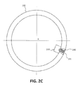
- conical flangeless sleeve 230 may be configured to repair a through hole in housing 205.
- Housing 205 may be any exemplary metal component including, for example, a compressor housing 105 as shown in FIG. 1 , turbine housing 107 as shown in FIG. 1 , and/or any other suitable metal component having one or more through holes.
- conical flangeless sleeve 230 may be capable of being installed in a conical void created in housing 205.
- Conical flangeless sleeve 230 may be configured to define at least a portion of a through hole in housing 205.
- conical flangeless sleeve 230 may be capable of removeably receiving a fastener 231.
- Fastener 231 may be removeably installable in the through hole defined in conical flangeless sleeve 230.
- Fastener 231 may be further configured to operatively couple to an internal structure 233, such as, for example, a nut, a vane, an air foil, a clip, and/or any other suitable structure.
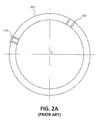
- engine components have been traditionally repaired with sleeve 220 and/or flanged sleeve 210.
- Initial or small repairs were traditionally made with sleeve 220.
- sleeve 220 can be inserted into the area defining a through hole that has been drilled out to restore the drilled out through hole to design requirements.
- sleeve 220 was not suitable for the repair because the fastener inserted into the through hole defined by sleeve 220 would cause sleeve 220 to liberate and/or pull toward the center point A of housing 205 and/or centerline A-A of gas turbine engine 100, as shown in FIG. 1 .
- flanged sleeve 210 may be employed.
- the flange of flanged sleeve 210 provided a wider support that engaged housing 205 and allowed larger through holes to be drilled in housing 205.
- the sleeve of flanged sleeve 210 was able to restore the through hole to design requirements.
- the flange of flanged sleeve 210 may create an interference with mating hardware on the outer surface of housing 205 due to the increased cross-section thickness created by the addition of the flange.
- Interference with mating hardware may include lack of thread engagement created by this increase in cross-section thickness.
- conical flangeless sleeve 230 remedies the issues associated with sleeve 220 and flanged sleeve 210 by distributing the support of conical flangeless sleeve 230 to a conical void defined in housing 205 (e.g., the damage, wear, and/or corrosion may be removed with a conical cutter and/or reamer creating a conical void).
- housing 205 supports the conical shape of conical flangeless sleeve 230, preventing conical flangeless sleeve 230 from pulling through housing 205 toward central point A, when a fastener 231 is inserted in the through hole of conical flangeless sleeve 230.
- conical flangeless sleeve 330 may comprise an outer surface 334 and inner surface 332, and a sloped annular surface 338. Conical flangeless sleeve 330 may further define a through hole 336 that extends between outer surface 334 and inner surface 332 about a center line of conical flangeless sleeve 330.
- Housing 305 e.g., a metal component
- the shape and or profile of sloped annular surface 338 may vary from through-hole to through-hole as illustrated, but maintain uniformity at any individual hole.
- the shape may correspond to a shape of annular recess 303 in which the entire surface is sloped, or may have the shape of annular recess 338A or 338B in which a portion of the flangeless sleeve maintains a non-conical or straight section of the shank.
- annular recess 303 may maintain a conical slope at any angle while maintaining uniformity for any given hole or, exhibit a portion of the flangeless sleeve that is non-conical. Illustrations provided provide a wide array of variations that may be used.
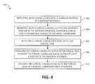
- Method 460 may comprise detecting, on the metal component (e.g., housing 305), a damaged portion at a fastener interface (Step 462).
- the metal component and/or housing 305 may be inspected at various through hole locations and/or fastener interfaces. These locations may be prone to corrosion, wear, and/or mechanical damage because of the interface between the fastener and an internal structure housed within housing 305.
- method 460 may further comprise removing with a cutter 350 the damaged portion at the fastener interface (Step 464).
- Cutter 350 may comprise a powerhead and a conical cutter 352 (e.g., a conical reamer).
- the powerhead for 354 may be configured to drive conical cutter 352.
- cutter 350 and more specifically conical cutter 352 may be configured to remove material from housing 305, when driven by powerhead 354.
- a conical void may be defined in the surface of the metal component and/or housing 305.
- method 460 may further comprise selecting a conical flangeless sleeve 330 to fill the conical void (step 466).
- a plurality of conical flangeless sleeves 330 may be provided.
- the conical flangeless sleeves 330 may be provided in various sizes.
- the overall height defined by the distance between inner surface 332 and outer surface 334 may be varied across a plurality of flangeless conical sleeves 330.
- the diameter of inner surface 332 outer surface 334 may be varied across a plurality of flangeless conical sleeves 330.
- the slope of sloped annular surface 338 may be varied over the plurality of conical flangeless sleeves 330.
- various standard-sized conical flangeless sleeves 330 may be provided. These standard-sized conical flangeless sleeves 330 may correspond to one or more conical cutter 352 provided with cutter 350. These standard-sized conical flangeless sleeves 330 may also correspond to determined cut depths of conical cutter 352 provided with cutter 350.
- a technician may select one size of the various size conical cutters 352 provided.
- the technician may remove material from housing 305 to define a particularly sized conical void in housing 305.
- the technician may cut the conical void to a particular depth or cut the void to a particular size with a selected conical cutter 352.
- the technician may further select a correspondingly sized conical flangeless sleeve for insertion in the conical void defined by conical cutter 352.
- method 460 may further comprise installing conical flangeless sleeve 330 in the conical void (Step 468).
- conical flangeless sleeve 330 may define at least a portion of the fastener interface defined within housing 305.
- conical flangeless sleeve 330 may restore the fastener interface and/or the through hole to original design requirements.
- Method 460 may further comprise securing conical flangeless sleeve 330 in the conical void of the metal component with a fastener (Step 470).
- conical flangeless sleeve 330 may be configured to receive and support the head of a fastener allowing the fastener to pass through hole 336 of conical flangeless sleeve 330 and attach to an internal structure housed within the metal component and/or housing 305.
- conical flangeless sleeves and associated methods of use may reduce the complexity repairs of metal components, the cost of repairs of metal components, and may extents the overall life of a metal component. While described herein in the context of gas turbine engine components such as, for example, the conical flangeless components and corresponding methods described herein may be used in any application and with any suitable metal components.
- references to "various embodiments”, “one embodiment”, “an embodiment”, “an example embodiment”, etc. indicate that the embodiment described may include a particular feature, structure, or characteristic, but every embodiment may not necessarily include the particular feature, structure, or characteristic. Moreover, such phrases are not necessarily referring to the same embodiment. Further, when a particular feature, structure, or characteristic is described in connection with an embodiment, it is submitted that it is within the knowledge of one skilled in the art to affect such feature, structure, or characteristic in connection with other embodiments whether or not explicitly described. After reading the description, it will be apparent to one skilled in the relevant art(s) how to implement the disclosure in alternative embodiments.
Landscapes
- Engineering & Computer Science (AREA)
- Mechanical Engineering (AREA)
- General Engineering & Computer Science (AREA)
- Chemical & Material Sciences (AREA)
- Combustion & Propulsion (AREA)
- Structures Of Non-Positive Displacement Pumps (AREA)
Applications Claiming Priority (1)
| Application Number | Priority Date | Filing Date | Title |
|---|---|---|---|
| US14/617,150 US20160230599A1 (en) | 2015-02-09 | 2015-02-09 | Flangeless conical sleeve and method of repair |
Publications (1)
| Publication Number | Publication Date |
|---|---|
| EP3053701A1 true EP3053701A1 (de) | 2016-08-10 |
Family
ID=55349647
Family Applications (1)
| Application Number | Title | Priority Date | Filing Date |
|---|---|---|---|
| EP16154185.9A Withdrawn EP3053701A1 (de) | 2015-02-09 | 2016-02-04 | Flanschlose konische hülse und reparaturverfahren |
Country Status (2)
| Country | Link |
|---|---|
| US (1) | US20160230599A1 (de) |
| EP (1) | EP3053701A1 (de) |
Citations (8)
| Publication number | Priority date | Publication date | Assignee | Title |
|---|---|---|---|---|
| US2607447A (en) * | 1946-02-26 | 1952-08-19 | Us Plywood Corp | Fastener |
| US3740820A (en) * | 1971-01-28 | 1973-06-26 | R Tarves | Method of repairing damaged holes in a boiler drum |
| FR2450520A1 (fr) * | 1979-02-27 | 1980-09-26 | Bosonnet Maurice Louis | Douille de reduction pour le montage de bougies d'allumage sur les moteurs a combustion interne |
| US4984347A (en) * | 1989-05-05 | 1991-01-15 | Mcdonnell Douglas Corporation | Method for attaching a doubler to a skin structure |
| DE4222248A1 (de) * | 1992-07-07 | 1994-01-13 | Rolf Burkart | Verbindungseinsatz |
| US20060088398A1 (en) * | 2004-10-07 | 2006-04-27 | Lund Casey B | Alignment washer |
| US20100077587A1 (en) * | 2008-09-26 | 2010-04-01 | Lufthansa Technik Ag | Method of repairing a housing of an aircraft engine |
| US20130232751A1 (en) * | 2012-03-12 | 2013-09-12 | United Technologies Corporation | Method for adhesive bonding plug details for composite structures |
Family Cites Families (18)
| Publication number | Priority date | Publication date | Assignee | Title |
|---|---|---|---|---|
| GB568460A (en) * | 1943-10-15 | 1945-04-05 | Harry Moss | Improvements in or relating to methods of fixing machines, parts of machines and thelike |
| US4164807A (en) * | 1974-03-19 | 1979-08-21 | King John O Jun | Method of forming a coldworked joint |
| IT1222810B (it) * | 1987-10-02 | 1990-09-12 | Nuovi Pignone Ind Meccaniche E | Perno smontabile per l'accoppiamento ruotabile di due elementi di ridotto ingombro assiale,particolarmente adatto per i leverismi delle macchine tessili |
| US4985979A (en) * | 1989-01-23 | 1991-01-22 | Mcdonnell Douglas Corporation | Method of installing interference fit sleeved fasteners having radiused intersection for stress coining |
| US5651172A (en) * | 1990-01-26 | 1997-07-29 | Ste. Ateliers De La Haute-Garonne-Ets Auriol Et Cie | Process for the assembly of materials and riveting member for carrying out the process |
| US6027279A (en) * | 1993-12-21 | 2000-02-22 | Kverneland Klepp As | Fixing clamp |
| US5521951A (en) * | 1994-09-23 | 1996-05-28 | General Electric Company | Reactor core shroud repair with tapered pins |
| US5575165A (en) * | 1995-01-25 | 1996-11-19 | Mcdonnell Douglas Corporation | Method of dent removal using a resonance damping vacuum blanket |
| US6370752B1 (en) * | 2000-04-21 | 2002-04-16 | General Electric Company | Method for repositioning or repairing holes |
| US7516534B2 (en) * | 2001-11-25 | 2009-04-14 | Stresswave, Inc. | Method for attaching a nut element to a metal structure |
| US6751841B2 (en) * | 2002-06-10 | 2004-06-22 | Sun Microsystems, Inc. | Riveting method |
| US7600666B2 (en) * | 2003-05-27 | 2009-10-13 | Rabinovich Joshua E | Repair with feedstock having conforming surfaces with a substrate |
| US7540122B2 (en) * | 2005-07-07 | 2009-06-02 | Trudeau Walter H | Drywall repair tool and method |
| US7722318B2 (en) * | 2007-02-13 | 2010-05-25 | United Technologies Corporation | Hole liners for repair of vane counterbore holes |
| US20090188748A1 (en) * | 2008-01-24 | 2009-07-30 | Honeywell International Inc. | Noise suppression panels and repair methods therefor |
| US9404374B2 (en) * | 2008-04-09 | 2016-08-02 | United Technologies Corporation | Trunnion hole repair utilizing interference fit inserts |
| US9593595B2 (en) * | 2014-04-14 | 2017-03-14 | Solar Turbines Incorporated | Method of remanufacturing a machine component |
| JP6450158B2 (ja) * | 2014-11-13 | 2019-01-09 | 三菱航空機株式会社 | 修理材における加工位置を特定する方法および修理方法 |
-
2015
- 2015-02-09 US US14/617,150 patent/US20160230599A1/en not_active Abandoned
-
2016
- 2016-02-04 EP EP16154185.9A patent/EP3053701A1/de not_active Withdrawn
Patent Citations (8)
| Publication number | Priority date | Publication date | Assignee | Title |
|---|---|---|---|---|
| US2607447A (en) * | 1946-02-26 | 1952-08-19 | Us Plywood Corp | Fastener |
| US3740820A (en) * | 1971-01-28 | 1973-06-26 | R Tarves | Method of repairing damaged holes in a boiler drum |
| FR2450520A1 (fr) * | 1979-02-27 | 1980-09-26 | Bosonnet Maurice Louis | Douille de reduction pour le montage de bougies d'allumage sur les moteurs a combustion interne |
| US4984347A (en) * | 1989-05-05 | 1991-01-15 | Mcdonnell Douglas Corporation | Method for attaching a doubler to a skin structure |
| DE4222248A1 (de) * | 1992-07-07 | 1994-01-13 | Rolf Burkart | Verbindungseinsatz |
| US20060088398A1 (en) * | 2004-10-07 | 2006-04-27 | Lund Casey B | Alignment washer |
| US20100077587A1 (en) * | 2008-09-26 | 2010-04-01 | Lufthansa Technik Ag | Method of repairing a housing of an aircraft engine |
| US20130232751A1 (en) * | 2012-03-12 | 2013-09-12 | United Technologies Corporation | Method for adhesive bonding plug details for composite structures |
Also Published As
| Publication number | Publication date |
|---|---|
| US20160230599A1 (en) | 2016-08-11 |
Similar Documents
| Publication | Publication Date | Title |
|---|---|---|
| US8579538B2 (en) | Turbine engine coupling stack | |
| US8616854B2 (en) | Nose cone assembly | |
| US9803485B2 (en) | Turbine segmented cover plate retention method | |
| EP2518282A2 (de) | Aufbaubefestigung mit Außengewinde für ein Fangehäuse | |
| US9784128B2 (en) | Systems and methods for engine bearings | |
| CN103161523A (zh) | 动态载荷减小系统 | |
| EP3026212A1 (de) | Blisk-kantenflächenhinterschnitt | |
| JP2008128251A (ja) | ステータシム溶接 | |
| US20090110552A1 (en) | Compressor stator vane repair with pin | |
| WO2014025758A1 (en) | Turbine blade staking pin | |
| EP3181945B1 (de) | Merkmale zur einer dämpfer- und dichtungsanordnung | |
| US8959743B2 (en) | Retaining ring removal tool | |
| EP3091200A1 (de) | Turbinengehäusekupplung | |
| EP3170982A1 (de) | Rotoranordnung zur verwendung in einem bläsertriebwerk und montageverfahren dafür | |
| EP2977564A1 (de) | Zapfluftventil mit resonanzkammer | |
| US10583913B2 (en) | Stud push out mount for a turbine engine spinner assembly having a spinner push out stud joint connecting through a counterbore of a spinner bolt hole | |
| EP3053701A1 (de) | Flanschlose konische hülse und reparaturverfahren | |
| US10415622B2 (en) | Method and system for hybrid gang channel bolted joint | |
| CN113811669B (zh) | 涡轮机械的分配器上的可移除销 | |
| CN108661727B (zh) | 涡轮发动机轴承组件及其组装方法 | |
| EP3018301A1 (de) | Schaufelarm mit geneigtem halteschlitz | |
| US6327844B1 (en) | Methods and apparatus for retaining flow restrictors within turbine engines | |
| US10830247B2 (en) | Remanufactured turbocharger shaft and method | |
| EP2933437A1 (de) | Systeme und verfahren für verdrehsicherungsfunktionen | |
| EP2564979A2 (de) | Buchse zum Reparieren von Umfangsflanschring |
Legal Events
| Date | Code | Title | Description |
|---|---|---|---|
| PUAI | Public reference made under article 153(3) epc to a published international application that has entered the european phase |
Free format text: ORIGINAL CODE: 0009012 |
|
| AK | Designated contracting states |
Kind code of ref document: A1 Designated state(s): AL AT BE BG CH CY CZ DE DK EE ES FI FR GB GR HR HU IE IS IT LI LT LU LV MC MK MT NL NO PL PT RO RS SE SI SK SM TR |
|
| AX | Request for extension of the european patent |
Extension state: BA ME |
|
| RAP1 | Party data changed (applicant data changed or rights of an application transferred) |
Owner name: UNITED TECHNOLOGIES CORPORATION |
|
| STAA | Information on the status of an ep patent application or granted ep patent |
Free format text: STATUS: REQUEST FOR EXAMINATION WAS MADE |
|
| 17P | Request for examination filed |
Effective date: 20170210 |
|
| RBV | Designated contracting states (corrected) |
Designated state(s): AL AT BE BG CH CY CZ DE DK EE ES FI FR GB GR HR HU IE IS IT LI LT LU LV MC MK MT NL NO PL PT RO RS SE SI SK SM TR |
|
| STAA | Information on the status of an ep patent application or granted ep patent |
Free format text: STATUS: EXAMINATION IS IN PROGRESS |
|
| 17Q | First examination report despatched |
Effective date: 20181207 |
|
| STAA | Information on the status of an ep patent application or granted ep patent |
Free format text: STATUS: THE APPLICATION HAS BEEN WITHDRAWN |
|
| 18W | Application withdrawn |
Effective date: 20190104 |