EP3054069B1 - Türgriffanordnung für ein kraftfahrzeug - Google Patents
Türgriffanordnung für ein kraftfahrzeug Download PDFInfo
- Publication number
- EP3054069B1 EP3054069B1 EP16152966.4A EP16152966A EP3054069B1 EP 3054069 B1 EP3054069 B1 EP 3054069B1 EP 16152966 A EP16152966 A EP 16152966A EP 3054069 B1 EP3054069 B1 EP 3054069B1
- Authority
- EP
- European Patent Office
- Prior art keywords
- handle
- actuation element
- vehicle door
- assembly according
- door handle
- Prior art date
- Legal status (The legal status is an assumption and is not a legal conclusion. Google has not performed a legal analysis and makes no representation as to the accuracy of the status listed.)
- Active
Links
Images


Classifications
-
- E—FIXED CONSTRUCTIONS
- E05—LOCKS; KEYS; WINDOW OR DOOR FITTINGS; SAFES
- E05B—LOCKS; ACCESSORIES THEREFOR; HANDCUFFS
- E05B85/00—Details of vehicle locks not provided for in groups E05B77/00 - E05B83/00
- E05B85/10—Handles
- E05B85/14—Handles pivoted about an axis parallel to the wing
- E05B85/16—Handles pivoted about an axis parallel to the wing a longitudinal grip part being pivoted at one end about an axis perpendicular to the longitudinal axis of the grip part
-
- E—FIXED CONSTRUCTIONS
- E05—LOCKS; KEYS; WINDOW OR DOOR FITTINGS; SAFES
- E05B—LOCKS; ACCESSORIES THEREFOR; HANDCUFFS
- E05B81/00—Power-actuated vehicle locks
- E05B81/54—Electrical circuits
- E05B81/64—Monitoring or sensing, e.g. by using switches or sensors
-
- E—FIXED CONSTRUCTIONS
- E05—LOCKS; KEYS; WINDOW OR DOOR FITTINGS; SAFES
- E05B—LOCKS; ACCESSORIES THEREFOR; HANDCUFFS
- E05B81/00—Power-actuated vehicle locks
- E05B81/54—Electrical circuits
- E05B81/64—Monitoring or sensing, e.g. by using switches or sensors
- E05B81/76—Detection of handle operation; Detection of a user approaching a handle; Electrical switching actions performed by door handles
-
- E—FIXED CONSTRUCTIONS
- E05—LOCKS; KEYS; WINDOW OR DOOR FITTINGS; SAFES
- E05B—LOCKS; ACCESSORIES THEREFOR; HANDCUFFS
- E05B17/00—Accessories in connection with locks
- E05B17/10—Illuminating devices on or for locks or keys; Transparent or translucent lock parts; Indicator lights
Definitions
- the invention relates to a vehicle door handle assembly.
- the invention relates to an outside door handle assembly with a sensor device for detecting an operation.
- the vehicle door handle assembly has a handle, wherein on an engaging side of the handle an actuating element is arranged, which is operable by an operator when gripping the handle.
- Door handles for motor vehicles are available in various designs, in particular, the door handles with a movable handle can be distinguished from those with a fixed handle.
- a handle part of the handle assembly to be undercut or engaged by the user is pivoted or translationally moved by force, and this movement is transmitted to a lock device in the door for actuation.
- the handles are arranged opposite the door largely immovable.
- electrically controlled door locks are used, which are led under the name "e-latch”.
- Such door locks are for example in the EP 0 584 499 A1 disclosed. In fixed door handles so no continuous mechanical chain of action is formed by the door handle on a door lock.
- the door lock is electrically energized in response to a detected actuation so that mechanical hardware can be reduced and cost and weight saved.
- Other door handles that have electrical sensor means are the EP 1 763 048 A1 , of the DE 20 2014 105 458 U1 as well as the EP 2 088 267 A2 refer to.
- the object of the invention is to provide an improved operator identification for door handles on motor vehicles.
- the door handle according to the invention has a handle, wherein the handle can be gripped around, under-gripped or overlapped.
- the handle is engaged behind in any section to exercise a required to open the door traction can.
- an actuator is arranged according to the invention.
- the actuating element is designed so that it is partially guided by a recess in the handle from the inside out, so a part protrudes into an inner cavity of the handle and a part of the actuating element protrudes out of the handle, outwardly and beyond the outer contour of the Handle protrudes at least slightly.
- the extent of extension, in which the actuating element projects outwardly beyond the outer contour of the handle can be extremely small. For example, a few tenths of a millimeter may be sufficient so that an operator hardly feels this survey and does not feel annoying.
- the actuating element In the interior of the handle, the actuating element is movably received, so that the actuating element for actuation through the recess of the handle is deflectable in the direction of the interior of the handle.
- An elastic return force is provided to bring the actuator back to its original position when a force is removed.
- a displacement, tilting or only deformation of the actuating element is allowed in the direction of the interior. In this case, very little freedom of movement or movement paths are sufficient.
- the handle protrudes outward beyond the outer contour of the handle, one can Be sufficient deformation, bending or the like of fractions of millimeters.
- the actuating element does not constitute a switch with a noticeable pressure point, but passes on the pressing force exerted when engaging behind in the form of a small deformation or displacement of the actuating element in the interior of the handle.
- the actuator is also at least partially formed with a metallic material.
- This metallic material is mounted in the interior of the handle on the actuator, laminated thereon, sprayed, painted or the entire actuator is mixed with a metallic material, such as a metallized plastic.
- This metallic material is essential, since an electrical assembly with at least one inductive distance sensor is arranged inside the handle. Inductive distance sensors detect changes in the position of metallic objects with respect to the distance sensor with high precision.
- the metallic material of the actuator shifts when actuated relative to the distance sensor, since the distance sensor is received stationary within the handle. Thus, a relative movement between actuator and distance sensor takes place as soon as the actuator shifts in the direction of the interior or is brought by the restoring force back to the original position.
- the actuating element is used accordingly to convey a change in distance or bearing change between the metallic components of the actuating element and the inductive distance sensor and to detect this change in distance. In this way, even small forces and thus actuating paths that occur during deformation or displacement of the actuating element detectable and coupled to the inductive distance sensor evaluation circuit is able to detect an operation of the door handle beyond doubt.
- the door handle thus formed is on the one hand very robust, the handle must not be deformable overall and also because the exterior is exposed only the mechanical actuator and also the electronic components protected inside the handle, possibly can be added in potted form.
- the actuator itself has no mandatory electrical components, it is only to ensure that metallic areas are formed in the material or on the material, which detect the distance sensors in the door handle. The mechanical components are decoupled in this way from the actual detection.
- the actuating element is formed from a plastic, which is partially covered with a metallic layer.
- the actuator on the outside so the side that touches a user, be modeled in its design of the handle surface, so that, if anything, only slight differences in perceptions are perceived in the touch.
- a metallic layer in the form of a sheet or a foil may be applied, since this area lies within the detection range of the inductive distance sensors.
- arranged in the interior of the door handle electrical assembly is formed with a circuit board on which the inductive distance sensor is formed, wherein the board is accommodated in a holder.
- the actuator is movably coupled to the bracket.
- both the electronic assembly is received in the holder and the actuator is movably coupled to this holder, so that a coherent unit is formed.
- a receptacle may be provided with an opening into which the circuit board is inserted and the actuating element may be fastened with spring elements on the holder.
- the actuating element is formed integrally with the holder.
- the design of the actuating element as a deformable tongue on the holder or receptacle for the electrical assembly is advantageous because then the holder can be formed with the actuating element in a molding process, wherein after the actuating element, if necessary, nor the metallic coating in the form of a film or a Coating is applied.
- circuit board is sealed in the holder with a potting compound.
- a potting of the electrical components provides protection of the electrical components and in particular of the inductive distance sensors and ensures a reliable function of the system.
- the door handle according to the invention is also in one embodiment in such a way that the actuating element is designed as an elongated element which extends along the longitudinal axis of a handle. Along this longitudinal extension several inductive distance sensors are arranged in the handle, which detect the approach of various portions of the actuating element.
- the actuating element can fulfill a plurality of operating functions, depending on which section of the actuating element is operated and which inductive distance sensor detects an actuation.
- the actuating element can in principle consist of an integral structure, which partially comprises metallic components, for example a plastic with metal particles.
- the actuating element can also be designed in several parts.
- a basic body made of a plastic can with a coating or a deferred component or another portion may be formed from a metallic material.
- a first, protruding from the handle portion of plastic may be formed and a second, located in the interior of the handle section may be formed of a metallic material.
- this second section which is formed from the metallic material, with spring tabs, which are supported in the interior of the handle.
- the restoring element itself will provide the required restoring force to move the actuator back to its original position after elimination of the actuating force.
- FIG. 1 a door handle assembly 1 with a grip 2 and a handle 3 is shown.
- the handle 3 is engaged behind the door in a range between the grip 2 and handle 3.
- the handle 3 has a recess for a lock cylinder and another actuator, but these components are not essential to the invention.
- FIG. 2a the handle 3 is shown isolated from the grip 2.
- FIG. 2b the handle 3 is shown in a view from behind.
- a portion 4 of the actuating element is visible, which protrudes through an opening 5 in the handle 3.
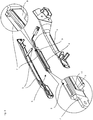
- FIG. 3 shows the handle 3 in an open state.
- the handle 3 is formed by two housing shells, wherein the opening 5 is formed in one of the housing shells.
- an actuating unit 6 is formed in the inner cavity of the handle.
- the actuating unit has a receptacle 7 made of a plastic.
- a circuit board 8 is formed in a cavity of this receptacle 7.
- inductive distance sensors are arranged as surface mountable components and facing with their detection range of the tongue 9.
- a tongue 9 is formed on the receptacle 7 also integrally a tongue 9 is formed.
- the projecting projection 4 shown in the previous figures which protrudes through the opening 5 of the handle.
- the approach 4 is touched by the user and when force the tongue 9 is slightly deformed together with the neck 4 in the direction of the receptacle 7.
- a metallic coating 11 is pushed on on the inside of the tongue 9, which faces the receptacle 7, a metallic coating 11 is pushed.
- This metallic coating 11 is provided to trigger the arranged on the board 8 inductive distance sensors or to detect by means of the sensors the distance of this coating 11 of the inductive distance sensors.
- the actuating element is formed from a plurality of components, namely the components 9, 4 and 11.
- FIG. 4 shows a sectional view of the handle with components arranged therein in the mounted state. It is clear that the projection 4 protrudes through the outer wall of the handle 3 and protrudes slightly beyond the outer contour of the handle 3. In the illustration, the tongue 9 and the deferred metallic part 11 are visible. The metallic overthrust 11 lies opposite the printed circuit board 8 with the inductive distance sensors arranged thereon, but is separated therefrom by the receptacle 7. Tongue 9 and cap 11 are in the normal position spaced from the receptacle 7, wherein an air gap between part 11 and receptacle 7 is formed.
- a movement of the components 9, 4 and 11 causes a change in the distance of the metallic region 11 relative to the board with the inductive distance sensors. This change in distance is detected and forwarded to an evaluation device (not shown).
- the evaluation device can be formed on the circuit board 8, or the signals of the inductive distance sensors can be routed to a separate evaluation unit.
- FIG. 5 shows the actuator unit with the receptacle 7, the tongue 9 and the neck 4, wherein the metallic part 11 of the actuating element is withdrawn from the tongue 9.
- the metallic part 11 has spring tongues, which support the tongue 9 relative to the receptacle 7 and provide a restoring force which push the approach 4 through the opening of the handle 3 to the starting position as soon as no force is exerted on the neck 4 becomes.
- the metallic part 11 thus has a dual function, namely on the one hand the provision of a restoring force and on the other hand, a means which is detectable by the inductive distance sensors in the circuit 8.
Landscapes
- Lock And Its Accessories (AREA)
Description
- Die Erfindung betrifft eine Fahrzeugtürgriffanordnung. Insbesondere betrifft die Erfindung eine Türaußengriffanordnung mit einer Sensoreinrichtung zur Erfassung einer Betätigung. Die Fahrzeugtürgriffanordnung weist eine Handhabe auf, wobei an einer zu hintergreifenden Seite der Handhabe ein Betätigungselement angeordnet ist, welches von einem Bediener beim Greifen der Handhabe betätigbar ist.
- Türgriffe für Kraftfahrzeuge sind in verschiedenen Gestaltungen verfügbar, wobei sich insbesondere die Türgriffe mit bewegbarer Handhabe von solchen mit feststehender Handhabe unterscheiden lassen. Bei einer bewegbaren Handhabe wird ein vom Benutzer zu untergreifender oder hintergreifender Handhabeteil der Griffanordnung durch Krafteinwirkung geschwenkt oder translatorisch bewegt und diese Bewegung wird auf eine Schlosseinrichtung in der Tür zur Betätigung übertragen. Bei feststehenden Türgriffen sind die Griffe gegenüber der Tür weitestehend unbeweglich angeordnet. In Kombination mit derart feststehenden Türgriffen kommen meist elektrisch angesteuerte Türschlösser zum Einsatz, die unter der Bezeichnung "e-Latch" geführt werden. Derartige Türschlösser sind beispielsweise in der
EP 0 584 499 A1 offenbart. Bei feststehenden Türgriffen wird also keine durchgehende mechanische Wirkungskette vom Türgriff auf ein Türschloss gebildet. Stattdessen wird das Türschloss in Abhängigkeit von einer detektierten Betätigung elektrisch angesteuert, so dass mechanische Hardware reduziert werden kann und Kosten und Gewicht einzusparen sind. Weitere Türgriffe, die elektrische Sensormittel aufweisen, sind derEP 1 763 048 A1 , derDE 20 2014 105 458 U1 sowie derEP 2 088 267 A2 zu entnehmen. - Zahlreiche Unterschiede gibt es bei der Art und Weise, wie die Betätigung eines feststehenden Türgriffes detektiert wird. Am Fahrzeugtürgriff können zu diesem Zweck Schalter oder kapazitive Sensoren oder auch Verformungssensoren eingesetzt werden, welche die Verformung des Türgriffes selbst erfassen.
- Die Bedienung derartiger feststehender Türgriffe erfordert jedoch entweder eine aufwendige und kostspielige Sensorik oder ist in ihrer Detektion nicht in erwünschtem Maße verlässlich. Die Aufgabe der Erfindung besteht darin, eine verbesserte Bedienerkennung für Türgriffe an Kraftfahrzeugen bereitzustellen.
- Diese Aufgabe wird durch eine Fahrzeugtürgriffanordnung mit einer Sensoreinrichtung gemäß den Merkmalen des Patentanspruches 1 gelöst.
- Der erfindungsgemäße Türgriff weist eine Handhabe auf, wobei die Handhabe umgreifbar, untergreifbar oder übergreifbar ausgebildet sein kann. Jedenfalls wird die Handhabe in irgendeinem Abschnitt hintergriffen, um eine zum Öffnen der Tür erforderliche Zugkraft ausüben zu können. In diesem zu hintergreifenden Bereich ist gemäß der Erfindung ein Betätigungselement angeordnet. Das Betätigungselement ist so ausgebildet, dass es abschnittsweise durch eine Ausnehmung in der Handhabe von innen nach außen geführt ist, ein Teil also in einem inneren Hohlraum der Handhabe hineinragt und ein Teil des Betätigungselementes aus der Handhabe heraus, nach außen hindurchragt und über die Außenkontur der Handhabe zumindest geringfügig vorsteht. Das Ausmaß der Erstreckung, in welchem das Betätigungselement nach außen über die Außenkontur der Handhabe hinaus vorsteht, kann äußerst gering sind. Beispielsweise können wenige zehntel Millimeter ausreichen, so dass ein Bediener diese Erhebung kaum spürt und nicht als störend empfindet.
- Im Inneren der Handhabe ist das Betätigungselement bewegbar aufgenommen, so dass das Betätigungselement zur Betätigung durch die Ausnehmung der Handhabe hindurch in Richtung des Inneren der Handhabe auslenkbar ist. Eine elastische Rückstellkraft ist vorgesehen, um das Betätigungselement wieder in die Ursprungslage zu bringen, wenn eine Kraftausübung wegfällt. Unter bewegbar ist in diesem Zusammenhang zu verstehen, dass eine Verschiebung, Verkippung oder nur Verformung des Betätigungselementes in Richtung des Innenraumes zugelassen wird. Hierbei sind bereits sehr geringe Bewegungsspielräume oder Bewegungswege ausreichend. Ebenso, wie die Handhabe über die Außenkontur der Handhabe nach außen heraussteht, kann ein Verformungsweg, Biegeweg oder ähnliches von Bruchteilen von Millimetern ausreichend sein.
- Angesichts dieser äußerst geringen Bewegungsräume ist es klar, dass das Betätigungselement keinen Schalter mit einem spürbaren Druckpunkt darstellt, sondern die beim Hintergreifen ausgeübte Druckkraft in Gestalt einer kleinen Verformung oder Verschiebung des Betätigungselementes in den Innenraum der Handhabe weiterleitet.
- Das Betätigungselement ist außerdem wenigstens abschnittsweise mit einem metallischen Material ausgebildet. Dieses metallische Material ist im Innenbereich der Handhabe am Betätigungselement angebracht, darauf auflaminiert, aufgesprüht, auflackiert oder das gesamte Betätigungselement ist mit einem metallischen Material versetzt, z.B. einem metallisierten Kunststoff. Dieses metallische Material ist wesentlich, da im Inneren der Handhabe eine elektrische Baugruppe mit wenigstens einem induktiven Abstandssensor angeordnet ist. Induktive Abstandssensoren erfassen Veränderungen in der Lage metallischer Gegenstände gegenüber dem Abstandssensor mit hoher Präzision. Das metallische Material des Betätigungselementes verschiebt sich bei Betätigung gegenüber dem Abstandssensor, da der Abstandssensor innerhalb der Handhabe ortsfest aufgenommen ist. So findet also eine Relativbewegung zwischen Betätigungselement und Abstandsensor statt, sobald sich das Betätigungselement in Richtung des Innenraumes verschiebt oder durch die Rückstellkraft wieder in die Ursprungsstellung gebracht wird. Das Betätigungselement wird entsprechend genutzt, um eine Abstandsänderung oder Lageränderung zwischen den metallischen Bestandteilen des Betätigungselementes und dem induktiven Abstandssensor zu vermitteln und diese Abstandsänderung zu erfassen. Auf diese Weise sind selbst geringe Kräfte und damit Betätigungswege, die bei Verformung oder bei Verschiebung des Betätigungselementes auftreten detektierbar und eine mit dem induktiven Abstandssensor gekoppelte Auswerteschaltung ist in der Lage, eine Betätigung des Türgriffes zweifelsfrei zu erkennen.
- Der derart gebildete Türgriff ist einerseits sehr robust, der Griff insgesamt nicht verformbar sein muss und auch weil dem Außenbereich nur das mechanische Betätigungselement ausgesetzt ist und außerdem die elektronischen Komponenten geschützt im Inneren der Handhabe, ggf. in vergossener Form aufgenommen sein können. Das Betätigungselement selbst weist keine zwingend erforderlichen elektrischen Komponenten auf, es ist lediglich sicherzustellen, dass metallische Bereiche im Material oder am Material ausgebildet sind, welche die Abstandssensoren im Türgriff detektieren. Die mechanischen Komponenten werden auf diese Weise von der eigentlichen Detektion entkoppelt.
- In einer Weiterbildung der Erfindung ist das Betätigungselement aus einem Kunststoff gebildet, welcher teilweise mit einer metallischen Schicht belegt ist.
- In dieser Gestaltung kann das Betätigungselement auf der Außenseite, also der Seite, die ein Benutzer berührt, in seiner Gestaltung der Griffoberfläche nachempfunden sein, so dass, wenn überhaupt, nur geringe Wahrnehmungsunterschiede im Tastgefühl wahrgenommen werden. Im Innenbereich kann eine metallische Schicht in Gestalt eines Bleches oder einer Folie aufgebracht sein, da dieser Bereich im Erfassungsbereich der induktiven Abstandssensoren liegt. Mit dieser Gestaltung kann außerdem gegenüber einer vollmetallischen oder teilmetallischen Ausbildung des Betätigungselementes Gewicht eingespart werden.
- In einer bevorzugten Ausführungsform der Erfindung ist die im Inneren des Türgriffs angeordnete elektrische Baugruppe mit einer Platine ausgebildet, auf welche der induktive Abstandssensor ausgebildet ist, wobei die Platine in einer Halterung aufgenommen ist. Das Betätigungselement ist mit der Halterung bewegbar gekoppelt.
- In dieser Gestaltung ist sowohl die elektronische Baueinheit in der Halterung aufgenommen als auch das Betätigungselement bewegbar mit dieser Halterung gekoppelt, so dass eine zusammenhängende Einheit gebildet ist. Beispielsweise kann eine Aufnahme mit einer Öffnung vorgesehen sein, in welche die Platine eingeschoben wird und das Betätigungselement kann mit Federelementen an der Halterung befestigt sein.
- Besonders bevorzugt ist es, wenn das Betätigungselement integral mit der Halterung ausgebildet ist. Insbesondere die Gestaltung des Betätigungselementes als verformbare Zunge an der Halterung oder Aufnahme für die elektrische Baugruppe ist vorteilhaft, da dann die Halterung mit dem Betätigungselement in einem Formvorgang gebildet werden kann, wobei danach dem Betätigungselement ggf. noch die metallische Beschichtung in Gestalt einer Folie oder eines Überzuges aufgebracht wird.
- Es ist vorteilhaft, wenn die Platine in der Halterung mit einer Vergussmasse vergossen ist. Durch die Ausnehmung in der Handhabe innerhalb derer das Betätigungselement bei Kraftausübung bewegbar ist, können Umwelteinflüsse in das Innere des Griffes vordringen. Ein Verguss der elektrischen Komponenten stellt einen Schutz der elektrischen Komponenten und insbesondere der induktiven Abstandssensoren dar und sichert eine verlässliche Funktion des Systems.
- Der erfindungsgemäße Türgriff ist außerdem in einer Ausführungsform so auszubilden, dass das Betätigungselement als langgestrecktes Element ausgebildet ist, welches sich entlang der Längsachse eine Handhabe erstreckt. Entlang dieser Längserstreckung sind in der Handhabe mehrere induktive Abstandssensoren angeordnet, welche die Annäherung verschiedener Abschnitte des Betätigungselementes erfassen.
- Werden mehrere induktive Abstandssensoren verwendet, um verschiedene Abschnitte des Betätigungselementes zu überwachen, kann beispielsweise eine Funktionalität bereitgestellt werden, die eine einseitige Betätigung des Betätigungselementes erfasst. Auf diese Weise kann das Betätigungselement mehrere Bedienfunktionen erfüllen, je nachdem welcher Abschnitt des Betätigungselementes bedient wird und welcher induktive Abstandssensor eine Betätigung detektiert.
- Wie bereits oben beschrieben, kann das Betätigungselement grundsätzlich aus einem integralen Aufbau bestehen, der teilweise metallische Komponenten aufweist, beispielsweise einem Kunststoff mit Metallpartikeln. Andererseits kann aber auch das Betätigungselement mehrteilig ausgebildet sein. Ein Grundkörper aus einem Kunststoff kann mit einem Überzug oder einem aufgeschobenen Bestandteil oder einem weiteren Abschnitt aus einem metallischen Material gebildet sein. Beispielsweise kann ein erster, aus der Handhabe herausragender Abschnitt aus Kunststoff gebildet sein und ein zweiter, im Inneren der Handhabe befindlicher Abschnitt aus einem metallischen Material gebildet sein. In einer Weiterbildung der Erfindung ist dieser zweite Abschnitt, der aus dem metallischen Material, mit Federlaschen ausgebildet, die sich im Inneren der Handhabe abstützen. Auf diese Weise wird das Rückstellelement selbst die erforderliche Rückstellkraft bereitstellen, die um das Betätigungselement nach Wegfallen der Betätigungskraft wieder in seiner Ausgangsstellung zu bewegen.
- Die partielle Bildung des Betätigungselementes aus einem Kunststoff bietet außerdem weitergehende Möglichkeiten der Gestaltung. Insbesondere kann in einer Weiterbildung der Erfindung das Material des Betätigungselementes als Lichtleiter verwendet werden, um Licht von einer im Inneren der Handhabe befindlichen Lichtquelle nach außen abzustrahlen. Da das Betätigungselement in dem hintergriffenen Bereich der Handhabe gerichtet ist, kann damit ein Bedienbereich für den Benutzer hinterleuchtet werden, also das Grifffeld ausgeleuchtet werden. Ein und dasselbe Element dient dann unterschiedlichen Zwecken, nämlich der Lichtleitung und der Betätigung gleichzeitig.
- Die Erfindung wird nun anhand der beiliegenden Figuren näher erläutert.
-
Figur 1 zeigt eine Türgriffanordnung gemäß einer ersten Ausführungsform mit Handhabe und Griffmulde in einer perspektivischen Ansicht; -
Figur 2a zeigt die separate Handhabe gemäß der ersten Ausführungsform in einer ersten perspektivischen Ansicht; -
Figur 2b zeigt die separate Handhabe gemäß der ersten Ausführungsform in einer zweiten perspektivischen Ansicht; -
Figur 3 zeigt eine Explosionsdarstellung der Handhabe mit Teilvergrößerungen; -
Figur 4 zeigt eine Schnittansicht der Türgriffanordnung gemäß der ersten Ausführungsform; -
Figur 5 zeigt eine Einzeldarstellung der in der Handhabe aufgenommenen Betätigungseinheit. - In
Figur 1 ist eine Türgriffanordnung 1 mit einer Griffmulde 2 und einer Handhabe 3 gezeigt. Die Handhabe 3 ist zur Türbetätigung in einem Bereich zwischen Griffmulde 2 und Handhabe 3 hintergreifbar. In diesem Beispiel weist die Handhabe 3 eine Ausnehmung für einen Schließzylinder und ein weiteres Betätigungselement auf, diese Komponenten sind für die Erfindung jedoch nicht wesentlich. - In
Figur 2a ist die Handhabe 3 isoliert von der Griffmulde 2 dargestellt. - In
Figur 2b ist die Handhabe 3 in einer Ansicht von hinten dargestellt. In dieser Ansicht wird ein Abschnitt 4 des Betätigungselementes sichtbar, der durch eine Öffnung 5 in der Handhabe 3 hinausragt. Wenn ein Benutzer die Handhabe 3 in dem Bereich zwischen der Handhabe 3 und der Griffmulde 2 hintergreift, kommt seine Hand unwillkürlich auf den Betätigungselement 4 zu liegen und übt beim Zug an der Handhabe 3 eine Kraft auf das Betätigungselement 4 aus. -
Figur 3 zeigt die Handhabe 3 in einem geöffneten Zustand. In diesem Ausführungsbeispiel wird die Handhabe 3 durch zwei Gehäuseschalen gebildet, wobei die Öffnung 5 in einer der Gehäuseschalen ausgebildet ist. Im inneren Hohlraum der Handhabe ist eine Betätigungseinheit 6 ausgebildet. Die Betätigungseinheit weist eine Aufnahme 7 aus einem Kunststoff auf. In einem Hohlraum dieser Aufnahme 7 ist eine Platine 8 ausgebildet. Auf dieser Platine sind induktive Abstandssensoren als oberflächenmontierbare Bauteile angeordnet und mit Ihrem Erfassungsbereich der Zunge 9 zugewandt. - An der Aufnahme 7 ist außerdem integral eine Zunge 9 angeformt. An der Zunge 9 ist wiederum integral der in den vorherigen Figuren gezeigte vorstehende Ansatz 4 angeformt, der durch die Öffnung 5 der Handhabe hinausragt. Der Ansatz 4 wird vom Benutzer berührt und bei Kraftausübung wird die Zunge 9 zusammen mit dem Ansatz 4 geringfügig in Richtung der Aufnahme 7 verformt. Auf an der Innenseite der Zunge 9,die der Aufnahme 7 zugewandt ist, ist ein metallischer Überzug 11 aufgeschoben. Dieser metallische Überzug 11 ist vorgesehen, um die auf der Platine 8 angeordneten induktiven Abstandssensoren auszulösen oder mittels der Sensoren den Abstand dieses Überzuges 11 von den induktiven Abstandssensoren zu erfassen. In diesem Ausführungsbeispiel wird also das Betätigungselement aus mehreren Komponenten gebildet, nämlich den Komponenten 9, 4 und 11.
-
Figur 4 zeigt eine Schnittansicht der Handhabe mit darin angeordneten Komponenten im montierten Zustand. Es wird deutlich, dass der Ansatz 4 durch die Außenwandung der Handhabe 3 hindurchragt und leicht über die Außenkontur der Handhabe 3 vorsteht. In der Darstellung werden auch die Zunge 9 sowie der aufgeschobene metallische Teil 11 sichtbar. Der metallische Überschub 11 liegt der Platine 8 mit dem darauf angeordneten induktiven Abstandssensoren gegenüber, ist von diesen aber durch die Aufnahme 7 getrennt. Zunge 9 und Überwurf 11 sind in der Normalstellung beabstandet zu der Aufnahme 7, wobei ein Luftspalt zwischen Teil 11 und Aufnahme 7 ausgebildet ist. - Eine Bewegung der Komponenten 9, 4 und 11 bewirkt eine Abstandsänderung des metallischen Bereiches 11 gegenüber der Platine mit den induktiven Abstandssensoren. Diese Abstandsänderung wird erfasst und einer Auswerteeinrichtung (nicht gezeigt) zugeleitet. Die Auswerteeinrichtung kann auf der Platine 8 ausgebildet sein, oder die Signale der induktiven Abstandssensoren können zu einer separaten Auswerteeinheit geleitet werden.
-
Figur 5 zeigt die Betätigungseinheit mit der Aufnahme 7, der Zunge 9 und dem Ansatz 4, wobei das metallische Teil 11 des Betätigungselementes von der Zunge 9 abgezogen ist. Es ist ersichtlich, dass das metallische Teil 11 Federzungen aufweist, welche die Zunge 9 gegenüber der Aufnahme 7 abstützten und eine Rückstellkraft bereitstellen, welche den Ansatz 4 durch die Öffnung der Handhabe 3 in die Ausgangsstellung zurückdrängen, sobald keine Kraft mehr auf den Ansatz 4 ausgeübt wird. Der metallische Teil 11 weist also eine Doppelfunktion auf, nämlich einerseits die Bereitstellung einer Rückstellkraft und andererseits ein Mittel, welches von den induktiven Abstandssensoren in der Schaltung 8 detektierbar ist.
Claims (9)
- Fahrzeugtürgriffanordnung (1) mit einer Sensoreinrichtung zum Erfassen einer Betätigung,
mit einer Handhabe (3), wobei an einer hintergreifbaren Seite der Handhabe (3) ein Betätigungselement (4, 9, 11) angeordnet ist, welches von einem Bediener beim Hintergreifen der Handhabe (3) betätigbar ist,
dadurch gekennzeichnet,
dass das Betätigungselement (4, 9, 11) durch eine Ausnehmung in der Handhabe (3) von einem inneren Hohlraum der Handhabe (3) durch eine Wandung der Handhabe (3) über die Außenkontur der Handhabe (3) hinaus nach außen hindurchragt,
wobei das Betätigungselement (4, 9, 11) im Inneren der Handhabe (3) bewegbar aufgenommen ist, so dass das Betätigungselement (4, 9, 11) zur Betätigung durch die Ausnehmung in Richtung des Inneren der Handhabe (3) entgegen einer elastischen Rückstellkraft bewegbar ist,
wobei das Betätigungselement (4, 9, 11) wenigstens abschnittsweise ein metallisches Material aufweist,
wobei im Inneren der Handhabe (3) eine elektrische Baugruppe mit wenigstens einem induktiven Abstandssensor angeordnet ist, wobei der induktive Abstandssensor beabstandet von dem Betätigungselement (4, 9, 11) ortsfest in der Handhabe (3) aufgenommen ist, so dass sich der Abstand des Betätigungselement (4, 9, 11) gegenüber dem induktiven Abstandssensor bei Bewegung des Betätigungselementes (4, 9, 11) verändert,
wobei eine Auswerteschaltung die Signale des induktiven Abstandssensors erfasst und eine Betätigung in Abhängigkeit von den Signalen erfasst und ein Ausgangssignal bereitstellt. - Fahrzeugtürgriffanordnung nach Anspruch 1, wobei das Betätigungselement (4, 9, 11) aus einem Kunststoff gebildet ist, welcher teilweise mit einer metallischen Schicht belegt ist.
- Fahrzeugtürgriffanordnung nach Anspruch 1 oder 2, wobei die elektrische Baugruppe eine Platine (8) aufweist, auf welcher der induktive Abstandssensor ausgebildet ist und wobei die Platine (8) in einer Halterung (7) aufgenommen ist,
wobei das Betätigungselement (4, 9, 11) mit der Halterung (7) bewegbar gekoppelt ist. - Fahrzeugtürgriffanordnung nach Anspruch 3, wobei das Betätigungselement (4, 9, 11) integral mit der Halterung (7) ausgebildet ist, insbesondere als verformbare Zunge.
- Fahrzeugtürgriffanordnung nach Anspruch 3 oder 4 wobei die Platine (8) mit dem induktiven Abstandssensor in der Halterung (7) mit einer Vergussmasse vergossen ist.
- Fahrzeugtürgriffanordnung nach einem der vorangehenden Ansprüche wobei das Betätigungselement (4, 9, 11) als langgestrecktes Element ausgebildet ist und sich entlang der Längsachse der Handhabe (3) erstreckt und wobei entlang der Längserstreckung in der Handhabe (3) mehrere induktive Abstandssensoren angeordnet sind, welche Annäherung verschiedener Abschnitte des Betätigungselementes (4, 9, 11) erfassen.
- Fahrzeugtürgriffanordnung nach einem der vorangehenden Ansprüche, wobei das Betätigungselement (4, 9, 11) mehrteilig ausgebildet ist, wobei ein durch die Handhabe (3) von innen nach außen hinausragender erster Abschnitt (4, 9) aus einem Kunststoff gebildet ist und ein metallischer Teil im Inneren der Handhabe (3) als zweiter Abschnitt (11) an dem ersten Abschnitt befestigt ist.
- Fahrzeugtürgriffanordnung nach Anspruch 7, wobei der zweite Abschnitt (11) mit Federlaschen ausgebildet ist, wobei sich die Federlaschen im Inneren der Handhabe (3) abstützen, um die Rückstellkraft des Betätigungselementes (4, 9, 11) bereitzustellen.
- Fahrzeugtürgriffanordnung nach Anspruch 7, wobei der erste Abschnitt (4, 9) des Betätigungselementes (4, 9, 11) aus einem lichtdurchlässigen Kunststoff gebildet ist und wobei im Inneren der Handhabe (3) eine Lichtquelle angeordnet ist, die Licht in den ersten Abschnitt (4, 9) einkoppelt, so dass Licht von der Lichtquelle durch den ersten Abschnitt (4, 9) in den Außenbereich der Handhabe (3) abstrahlbar ist.
Applications Claiming Priority (1)
| Application Number | Priority Date | Filing Date | Title |
|---|---|---|---|
| DE102015101733.4A DE102015101733A1 (de) | 2015-02-06 | 2015-02-06 | Türgriffanordnung für ein Kraftfahrzeug |
Publications (2)
| Publication Number | Publication Date |
|---|---|
| EP3054069A1 EP3054069A1 (de) | 2016-08-10 |
| EP3054069B1 true EP3054069B1 (de) | 2018-06-27 |
Family
ID=55237579
Family Applications (1)
| Application Number | Title | Priority Date | Filing Date |
|---|---|---|---|
| EP16152966.4A Active EP3054069B1 (de) | 2015-02-06 | 2016-01-27 | Türgriffanordnung für ein kraftfahrzeug |
Country Status (3)
| Country | Link |
|---|---|
| US (1) | US9995065B2 (de) |
| EP (1) | EP3054069B1 (de) |
| DE (1) | DE102015101733A1 (de) |
Families Citing this family (13)
| Publication number | Priority date | Publication date | Assignee | Title |
|---|---|---|---|---|
| JP6064806B2 (ja) * | 2013-06-21 | 2017-01-25 | アイシン精機株式会社 | 車両用のドアハンドル |
| US11286694B2 (en) * | 2015-07-13 | 2022-03-29 | Huf Hülsbeck & Fürst Gmbh & Co. Kg | Exterior door handle for a vehicle |
| USD859955S1 (en) * | 2016-02-25 | 2019-09-17 | Southco, Inc. | Latch actuator |
| JP6564524B2 (ja) * | 2016-03-17 | 2019-08-21 | 株式会社ホンダアクセス | アシストグリップ |
| FR3065418B1 (fr) * | 2017-04-25 | 2019-04-19 | Continental Automotive France | Procede d'activation d'une fonction vehicule a partir d'un dispositif d'acces portable d et module d'activation associe |
| US11441341B2 (en) | 2017-12-05 | 2022-09-13 | Adac Plastics, Inc. | Door handle assembly for a motor vehicle |
| DE102018107503A1 (de) * | 2018-03-28 | 2019-10-02 | Huf Hülsbeck & Fürst Gmbh & Co. Kg | Griffvorrichtung für eine Tür oder eine Klappe |
| FR3083877B1 (fr) * | 2018-07-12 | 2020-06-12 | Continental Automotive France | Module d'activation detectant simultanement une approche et un appui d'un utilisateur avec une antenne haute frequence mobile |
| DE102019109395B4 (de) * | 2019-04-10 | 2023-08-24 | Dr. Ing. H.C. F. Porsche Aktiengesellschaft | Fahrzeugtür |
| DE102019206282B4 (de) * | 2019-05-02 | 2025-06-26 | Witte Automotive Gmbh | Türentriegelungs- und/oder Türöffnungsmechanismus mit einer Betätigungsvorrichtung |
| FR3096711B1 (fr) | 2019-05-28 | 2021-07-09 | Continental Automotive Gmbh | Capteur inductif pour véhicule |
| US11719021B2 (en) | 2019-08-06 | 2023-08-08 | Schlage Lock Company Llc | Sensing and control of access control devices |
| DE102019134953A1 (de) * | 2019-12-18 | 2021-06-24 | Huf Hülsbeck & Fürst Gmbh & Co. Kg | Induktive Sensoranordnung zur Erfassung einer Lageänderung eines Betätigungselements |
Family Cites Families (12)
| Publication number | Priority date | Publication date | Assignee | Title |
|---|---|---|---|---|
| DE4228234A1 (de) | 1992-08-25 | 1994-03-03 | Bayerische Motoren Werke Ag | Türschloß für Kraftfahrzeuge |
| DE10031664C1 (de) * | 2000-06-29 | 2002-01-03 | Kiekert Ag | Betätigungseinrichtung |
| DE10131436B4 (de) * | 2001-06-29 | 2006-07-27 | Daimlerchrysler Ag | Außentürgriff, insbesondere für Kraftfahrzeuge |
| DE10309148A1 (de) * | 2003-03-02 | 2004-09-23 | Huf Hülsbeck & Fürst Gmbh & Co. Kg | Vorrichtung zum Betätigen eines elektrischen Schließsystems und/oder eines in der Tür oder Klappe oder dergleichen eingebauten Schlosses für Fahrzeuge |
| JP4310699B2 (ja) * | 2004-06-22 | 2009-08-12 | アイシン精機株式会社 | スイッチ装置 |
| DE102005031441A1 (de) * | 2005-07-04 | 2007-01-11 | Huf Hülsbeck & Fürst Gmbh & Co. Kg | Griffvorrichtung |
| DE102008000273A1 (de) * | 2008-02-11 | 2009-08-13 | Huf Hülsbeck & Fürst Gmbh & Co. Kg | Sensoranordnung mit einem mechano-elektrischen Wandler und einem darauf einwirkenden deformierbaren mechanischen Element mit einem matastabilen Zustand |
| JP5107458B2 (ja) * | 2009-06-11 | 2012-12-26 | トヨタ自動車株式会社 | 電磁結合装置および車両用ドア |
| JP2013509283A (ja) * | 2009-11-02 | 2013-03-14 | エルジー エレクトロニクス インコーポレイティド | 洗濯方法及び洗濯機 |
| US9957737B2 (en) * | 2012-06-29 | 2018-05-01 | Ford Global Technologies, Llc | Flush-mounted door handle for vehicles |
| DE102012106526A1 (de) * | 2012-07-18 | 2014-01-23 | Huf Hülsbeck & Fürst Gmbh & Co. Kg | Handhabe mit zwei Elektroden |
| US9416565B2 (en) * | 2013-11-21 | 2016-08-16 | Ford Global Technologies, Llc | Piezo based energy harvesting for e-latch systems |
-
2015
- 2015-02-06 DE DE102015101733.4A patent/DE102015101733A1/de not_active Withdrawn
-
2016
- 2016-01-27 EP EP16152966.4A patent/EP3054069B1/de active Active
- 2016-02-03 US US15/014,860 patent/US9995065B2/en active Active
Non-Patent Citations (1)
| Title |
|---|
| None * |
Also Published As
| Publication number | Publication date |
|---|---|
| DE102015101733A1 (de) | 2016-08-11 |
| US20160230429A1 (en) | 2016-08-11 |
| US9995065B2 (en) | 2018-06-12 |
| EP3054069A1 (de) | 2016-08-10 |
Similar Documents
| Publication | Publication Date | Title |
|---|---|---|
| EP3054069B1 (de) | Türgriffanordnung für ein kraftfahrzeug | |
| EP4025750B1 (de) | Betätigungsvorrichtung mit bewegbarem schaltelement, fahrzeug sowie betätigungsverfahren | |
| EP3322868B1 (de) | Türgriffanordnung für ein kraftfahrzeug | |
| DE102020122424A9 (de) | Betätigungsvorrichtung zur Montage an einem Fahrzeugteil, Fahrzeug sowie Betätigungsverfahren zum Auslösen einer Fahrzeugfunktion | |
| EP3097642B1 (de) | Betätigungseinrichtung für ein kraftfahrzeug | |
| EP2633535A1 (de) | Schaltbedienfeld | |
| EP3049288B1 (de) | Baugruppe für betätigung einer fahrzeugfunktion | |
| WO2017009077A1 (de) | Türgriffanordnung für ein kraftfahrzeug | |
| EP3462420A1 (de) | Funkschlüssel für kraftfahrzeuge | |
| EP2102437B1 (de) | Sensorischer kraftfahrzeugtürgriff mit taktiler rückmeldung | |
| EP2492786A1 (de) | Bedienelement | |
| EP3149263B1 (de) | Türgriff für ein kraftfahrzeug | |
| EP3309966A1 (de) | Kapazitive schalt-vorrichtung | |
| DE102015111311A1 (de) | Türgriffanordnung für ein Kraftfahrzeug | |
| EP2088251A2 (de) | Vorrichtung zur elektrischen Auslösung eines Spülvorgangs in einer sanitären Einrichtung | |
| EP2348638B1 (de) | Kapazitiver Berührungs- und/oder Annäherungsschalter | |
| WO2014173518A1 (de) | Bedienvorrichtung für ein kraftfahrzeug | |
| EP3262758B1 (de) | Bedienvorrichtung, insbesondere für ein elektronisches haushaltsgerät | |
| EP3927921A1 (de) | BETÄTIGUNGSEINRICHTUNG FÜR DEN KRAFTFAHRZEUGAUßENBEREICH | |
| DE202015106587U1 (de) | Türgriffanordnung für ein Kraftfahrzeug | |
| DE102017119235B3 (de) | Kraftfahrzeugbedienvorrichtung sowie Verfahren zur Herstellung einer zumindest teilweise elektrisch leitfähigen Bedieneinheit für eine Kraftfahrzeugbedienvorrichtung | |
| DE102017127222B4 (de) | Verfahren zum Betreiben einer kapazitiven Eingabevorrichtung; kapazitive Eingabevorrichtung; Kraftfahrzeug | |
| WO2016055139A1 (de) | Bedienvorrichtung, insbesondere für ein elektronisches haushaltsgerät | |
| DE102020102887A1 (de) | Betätigungsvorrichtung mit Verkleidungselement, Fahrzeug, sowie Verfahren | |
| DE102018128170A1 (de) | Elektrischer Schalter und Verfahren zum Herstellen eines elektrischen Schalters |
Legal Events
| Date | Code | Title | Description |
|---|---|---|---|
| PUAI | Public reference made under article 153(3) epc to a published international application that has entered the european phase |
Free format text: ORIGINAL CODE: 0009012 |
|
| AK | Designated contracting states |
Kind code of ref document: A1 Designated state(s): AL AT BE BG CH CY CZ DE DK EE ES FI FR GB GR HR HU IE IS IT LI LT LU LV MC MK MT NL NO PL PT RO RS SE SI SK SM TR |
|
| AX | Request for extension of the european patent |
Extension state: BA ME |
|
| 17P | Request for examination filed |
Effective date: 20160905 |
|
| RBV | Designated contracting states (corrected) |
Designated state(s): AL AT BE BG CH CY CZ DE DK EE ES FI FR GB GR HR HU IE IS IT LI LT LU LV MC MK MT NL NO PL PT RO RS SE SI SK SM TR |
|
| GRAP | Despatch of communication of intention to grant a patent |
Free format text: ORIGINAL CODE: EPIDOSNIGR1 |
|
| STAA | Information on the status of an ep patent application or granted ep patent |
Free format text: STATUS: GRANT OF PATENT IS INTENDED |
|
| RIC1 | Information provided on ipc code assigned before grant |
Ipc: E05B 17/10 20060101ALN20180108BHEP Ipc: E05B 81/76 20140101AFI20180108BHEP |
|
| INTG | Intention to grant announced |
Effective date: 20180206 |
|
| GRAS | Grant fee paid |
Free format text: ORIGINAL CODE: EPIDOSNIGR3 |
|
| GRAA | (expected) grant |
Free format text: ORIGINAL CODE: 0009210 |
|
| STAA | Information on the status of an ep patent application or granted ep patent |
Free format text: STATUS: THE PATENT HAS BEEN GRANTED |
|
| AK | Designated contracting states |
Kind code of ref document: B1 Designated state(s): AL AT BE BG CH CY CZ DE DK EE ES FI FR GB GR HR HU IE IS IT LI LT LU LV MC MK MT NL NO PL PT RO RS SE SI SK SM TR |
|
| REG | Reference to a national code |
Ref country code: GB Ref legal event code: FG4D Free format text: NOT ENGLISH |
|
| REG | Reference to a national code |
Ref country code: AT Ref legal event code: REF Ref document number: 1012505 Country of ref document: AT Kind code of ref document: T Effective date: 20180715 |
|
| REG | Reference to a national code |
Ref country code: IE Ref legal event code: FG4D Free format text: LANGUAGE OF EP DOCUMENT: GERMAN |
|
| REG | Reference to a national code |
Ref country code: DE Ref legal event code: R096 Ref document number: 502016001312 Country of ref document: DE |
|
| PG25 | Lapsed in a contracting state [announced via postgrant information from national office to epo] |
Ref country code: BG Free format text: LAPSE BECAUSE OF FAILURE TO SUBMIT A TRANSLATION OF THE DESCRIPTION OR TO PAY THE FEE WITHIN THE PRESCRIBED TIME-LIMIT Effective date: 20180927 Ref country code: FI Free format text: LAPSE BECAUSE OF FAILURE TO SUBMIT A TRANSLATION OF THE DESCRIPTION OR TO PAY THE FEE WITHIN THE PRESCRIBED TIME-LIMIT Effective date: 20180627 Ref country code: NO Free format text: LAPSE BECAUSE OF FAILURE TO SUBMIT A TRANSLATION OF THE DESCRIPTION OR TO PAY THE FEE WITHIN THE PRESCRIBED TIME-LIMIT Effective date: 20180927 Ref country code: SE Free format text: LAPSE BECAUSE OF FAILURE TO SUBMIT A TRANSLATION OF THE DESCRIPTION OR TO PAY THE FEE WITHIN THE PRESCRIBED TIME-LIMIT Effective date: 20180627 Ref country code: LT Free format text: LAPSE BECAUSE OF FAILURE TO SUBMIT A TRANSLATION OF THE DESCRIPTION OR TO PAY THE FEE WITHIN THE PRESCRIBED TIME-LIMIT Effective date: 20180627 |
|
| REG | Reference to a national code |
Ref country code: NL Ref legal event code: MP Effective date: 20180627 |
|
| REG | Reference to a national code |
Ref country code: LT Ref legal event code: MG4D |
|
| PG25 | Lapsed in a contracting state [announced via postgrant information from national office to epo] |
Ref country code: RS Free format text: LAPSE BECAUSE OF FAILURE TO SUBMIT A TRANSLATION OF THE DESCRIPTION OR TO PAY THE FEE WITHIN THE PRESCRIBED TIME-LIMIT Effective date: 20180627 Ref country code: HR Free format text: LAPSE BECAUSE OF FAILURE TO SUBMIT A TRANSLATION OF THE DESCRIPTION OR TO PAY THE FEE WITHIN THE PRESCRIBED TIME-LIMIT Effective date: 20180627 Ref country code: GR Free format text: LAPSE BECAUSE OF FAILURE TO SUBMIT A TRANSLATION OF THE DESCRIPTION OR TO PAY THE FEE WITHIN THE PRESCRIBED TIME-LIMIT Effective date: 20180928 Ref country code: LV Free format text: LAPSE BECAUSE OF FAILURE TO SUBMIT A TRANSLATION OF THE DESCRIPTION OR TO PAY THE FEE WITHIN THE PRESCRIBED TIME-LIMIT Effective date: 20180627 |
|
| PG25 | Lapsed in a contracting state [announced via postgrant information from national office to epo] |
Ref country code: NL Free format text: LAPSE BECAUSE OF FAILURE TO SUBMIT A TRANSLATION OF THE DESCRIPTION OR TO PAY THE FEE WITHIN THE PRESCRIBED TIME-LIMIT Effective date: 20180627 |
|
| PG25 | Lapsed in a contracting state [announced via postgrant information from national office to epo] |
Ref country code: EE Free format text: LAPSE BECAUSE OF FAILURE TO SUBMIT A TRANSLATION OF THE DESCRIPTION OR TO PAY THE FEE WITHIN THE PRESCRIBED TIME-LIMIT Effective date: 20180627 Ref country code: SK Free format text: LAPSE BECAUSE OF FAILURE TO SUBMIT A TRANSLATION OF THE DESCRIPTION OR TO PAY THE FEE WITHIN THE PRESCRIBED TIME-LIMIT Effective date: 20180627 Ref country code: IS Free format text: LAPSE BECAUSE OF FAILURE TO SUBMIT A TRANSLATION OF THE DESCRIPTION OR TO PAY THE FEE WITHIN THE PRESCRIBED TIME-LIMIT Effective date: 20181027 Ref country code: RO Free format text: LAPSE BECAUSE OF FAILURE TO SUBMIT A TRANSLATION OF THE DESCRIPTION OR TO PAY THE FEE WITHIN THE PRESCRIBED TIME-LIMIT Effective date: 20180627 Ref country code: CZ Free format text: LAPSE BECAUSE OF FAILURE TO SUBMIT A TRANSLATION OF THE DESCRIPTION OR TO PAY THE FEE WITHIN THE PRESCRIBED TIME-LIMIT Effective date: 20180627 Ref country code: PL Free format text: LAPSE BECAUSE OF FAILURE TO SUBMIT A TRANSLATION OF THE DESCRIPTION OR TO PAY THE FEE WITHIN THE PRESCRIBED TIME-LIMIT Effective date: 20180627 |
|
| PG25 | Lapsed in a contracting state [announced via postgrant information from national office to epo] |
Ref country code: SM Free format text: LAPSE BECAUSE OF FAILURE TO SUBMIT A TRANSLATION OF THE DESCRIPTION OR TO PAY THE FEE WITHIN THE PRESCRIBED TIME-LIMIT Effective date: 20180627 Ref country code: IT Free format text: LAPSE BECAUSE OF FAILURE TO SUBMIT A TRANSLATION OF THE DESCRIPTION OR TO PAY THE FEE WITHIN THE PRESCRIBED TIME-LIMIT Effective date: 20180627 Ref country code: ES Free format text: LAPSE BECAUSE OF FAILURE TO SUBMIT A TRANSLATION OF THE DESCRIPTION OR TO PAY THE FEE WITHIN THE PRESCRIBED TIME-LIMIT Effective date: 20180627 |
|
| REG | Reference to a national code |
Ref country code: DE Ref legal event code: R097 Ref document number: 502016001312 Country of ref document: DE |
|
| PLBE | No opposition filed within time limit |
Free format text: ORIGINAL CODE: 0009261 |
|
| STAA | Information on the status of an ep patent application or granted ep patent |
Free format text: STATUS: NO OPPOSITION FILED WITHIN TIME LIMIT |
|
| PG25 | Lapsed in a contracting state [announced via postgrant information from national office to epo] |
Ref country code: DK Free format text: LAPSE BECAUSE OF FAILURE TO SUBMIT A TRANSLATION OF THE DESCRIPTION OR TO PAY THE FEE WITHIN THE PRESCRIBED TIME-LIMIT Effective date: 20180627 |
|
| 26N | No opposition filed |
Effective date: 20190328 |
|
| PG25 | Lapsed in a contracting state [announced via postgrant information from national office to epo] |
Ref country code: MC Free format text: LAPSE BECAUSE OF FAILURE TO SUBMIT A TRANSLATION OF THE DESCRIPTION OR TO PAY THE FEE WITHIN THE PRESCRIBED TIME-LIMIT Effective date: 20180627 Ref country code: SI Free format text: LAPSE BECAUSE OF FAILURE TO SUBMIT A TRANSLATION OF THE DESCRIPTION OR TO PAY THE FEE WITHIN THE PRESCRIBED TIME-LIMIT Effective date: 20180627 |
|
| REG | Reference to a national code |
Ref country code: CH Ref legal event code: PL |
|
| PG25 | Lapsed in a contracting state [announced via postgrant information from national office to epo] |
Ref country code: LU Free format text: LAPSE BECAUSE OF NON-PAYMENT OF DUE FEES Effective date: 20190127 |
|
| REG | Reference to a national code |
Ref country code: BE Ref legal event code: MM Effective date: 20190131 |
|
| REG | Reference to a national code |
Ref country code: IE Ref legal event code: MM4A |
|
| PG25 | Lapsed in a contracting state [announced via postgrant information from national office to epo] |
Ref country code: AL Free format text: LAPSE BECAUSE OF FAILURE TO SUBMIT A TRANSLATION OF THE DESCRIPTION OR TO PAY THE FEE WITHIN THE PRESCRIBED TIME-LIMIT Effective date: 20180627 Ref country code: BE Free format text: LAPSE BECAUSE OF NON-PAYMENT OF DUE FEES Effective date: 20190131 |
|
| PG25 | Lapsed in a contracting state [announced via postgrant information from national office to epo] |
Ref country code: CH Free format text: LAPSE BECAUSE OF NON-PAYMENT OF DUE FEES Effective date: 20190131 Ref country code: LI Free format text: LAPSE BECAUSE OF NON-PAYMENT OF DUE FEES Effective date: 20190131 |
|
| PG25 | Lapsed in a contracting state [announced via postgrant information from national office to epo] |
Ref country code: IE Free format text: LAPSE BECAUSE OF NON-PAYMENT OF DUE FEES Effective date: 20190127 |
|
| PG25 | Lapsed in a contracting state [announced via postgrant information from national office to epo] |
Ref country code: TR Free format text: LAPSE BECAUSE OF FAILURE TO SUBMIT A TRANSLATION OF THE DESCRIPTION OR TO PAY THE FEE WITHIN THE PRESCRIBED TIME-LIMIT Effective date: 20180627 |
|
| PG25 | Lapsed in a contracting state [announced via postgrant information from national office to epo] |
Ref country code: MT Free format text: LAPSE BECAUSE OF FAILURE TO SUBMIT A TRANSLATION OF THE DESCRIPTION OR TO PAY THE FEE WITHIN THE PRESCRIBED TIME-LIMIT Effective date: 20180627 Ref country code: PT Free format text: LAPSE BECAUSE OF FAILURE TO SUBMIT A TRANSLATION OF THE DESCRIPTION OR TO PAY THE FEE WITHIN THE PRESCRIBED TIME-LIMIT Effective date: 20181029 |
|
| GBPC | Gb: european patent ceased through non-payment of renewal fee |
Effective date: 20200127 |
|
| PG25 | Lapsed in a contracting state [announced via postgrant information from national office to epo] |
Ref country code: GB Free format text: LAPSE BECAUSE OF NON-PAYMENT OF DUE FEES Effective date: 20200127 |
|
| PG25 | Lapsed in a contracting state [announced via postgrant information from national office to epo] |
Ref country code: CY Free format text: LAPSE BECAUSE OF FAILURE TO SUBMIT A TRANSLATION OF THE DESCRIPTION OR TO PAY THE FEE WITHIN THE PRESCRIBED TIME-LIMIT Effective date: 20180627 |
|
| PG25 | Lapsed in a contracting state [announced via postgrant information from national office to epo] |
Ref country code: HU Free format text: LAPSE BECAUSE OF FAILURE TO SUBMIT A TRANSLATION OF THE DESCRIPTION OR TO PAY THE FEE WITHIN THE PRESCRIBED TIME-LIMIT; INVALID AB INITIO Effective date: 20160127 |
|
| REG | Reference to a national code |
Ref country code: AT Ref legal event code: MM01 Ref document number: 1012505 Country of ref document: AT Kind code of ref document: T Effective date: 20210127 |
|
| PG25 | Lapsed in a contracting state [announced via postgrant information from national office to epo] |
Ref country code: AT Free format text: LAPSE BECAUSE OF NON-PAYMENT OF DUE FEES Effective date: 20210127 |
|
| PGFP | Annual fee paid to national office [announced via postgrant information from national office to epo] |
Ref country code: FR Payment date: 20220120 Year of fee payment: 7 |
|
| PG25 | Lapsed in a contracting state [announced via postgrant information from national office to epo] |
Ref country code: MK Free format text: LAPSE BECAUSE OF FAILURE TO SUBMIT A TRANSLATION OF THE DESCRIPTION OR TO PAY THE FEE WITHIN THE PRESCRIBED TIME-LIMIT Effective date: 20180627 |
|
| P01 | Opt-out of the competence of the unified patent court (upc) registered |
Effective date: 20230507 |
|
| PG25 | Lapsed in a contracting state [announced via postgrant information from national office to epo] |
Ref country code: FR Free format text: LAPSE BECAUSE OF NON-PAYMENT OF DUE FEES Effective date: 20230131 |
|
| PGFP | Annual fee paid to national office [announced via postgrant information from national office to epo] |
Ref country code: DE Payment date: 20260131 Year of fee payment: 11 |