EP3054107B1 - Turbinenanordnung mit einer sperreinrichtung des rotorsystems - Google Patents
Turbinenanordnung mit einer sperreinrichtung des rotorsystems Download PDFInfo
- Publication number
- EP3054107B1 EP3054107B1 EP16154368.1A EP16154368A EP3054107B1 EP 3054107 B1 EP3054107 B1 EP 3054107B1 EP 16154368 A EP16154368 A EP 16154368A EP 3054107 B1 EP3054107 B1 EP 3054107B1
- Authority
- EP
- European Patent Office
- Prior art keywords
- case
- rotor
- fuse
- turbine assembly
- assembly
- Prior art date
- Legal status (The legal status is an assumption and is not a legal conclusion. Google has not performed a legal analysis and makes no representation as to the accuracy of the status listed.)
- Active
Links
Images


Classifications
-
- F—MECHANICAL ENGINEERING; LIGHTING; HEATING; WEAPONS; BLASTING
- F01—MACHINES OR ENGINES IN GENERAL; ENGINE PLANTS IN GENERAL; STEAM ENGINES
- F01D—NON-POSITIVE DISPLACEMENT MACHINES OR ENGINES, e.g. STEAM TURBINES
- F01D19/00—Starting of machines or engines; Regulating, controlling, or safety means in connection therewith
-
- F—MECHANICAL ENGINEERING; LIGHTING; HEATING; WEAPONS; BLASTING
- F01—MACHINES OR ENGINES IN GENERAL; ENGINE PLANTS IN GENERAL; STEAM ENGINES
- F01D—NON-POSITIVE DISPLACEMENT MACHINES OR ENGINES, e.g. STEAM TURBINES
- F01D21/00—Shutting-down of machines or engines, e.g. in emergency; Regulating, controlling, or safety means not otherwise provided for
-
- B—PERFORMING OPERATIONS; TRANSPORTING
- B64—AIRCRAFT; AVIATION; COSMONAUTICS
- B64D—EQUIPMENT FOR FITTING IN OR TO AIRCRAFT; FLIGHT SUITS; PARACHUTES; ARRANGEMENT OR MOUNTING OF POWER PLANTS OR PROPULSION TRANSMISSIONS IN AIRCRAFT
- B64D7/00—Arrangement of military equipment, e.g. armaments, armament accessories or military shielding, in aircraft; Adaptations of armament mountings for aircraft
-
- F—MECHANICAL ENGINEERING; LIGHTING; HEATING; WEAPONS; BLASTING
- F01—MACHINES OR ENGINES IN GENERAL; ENGINE PLANTS IN GENERAL; STEAM ENGINES
- F01D—NON-POSITIVE DISPLACEMENT MACHINES OR ENGINES, e.g. STEAM TURBINES
- F01D25/00—Component parts, details, or accessories, not provided for in, or of interest apart from, other groups
- F01D25/24—Casings; Casing parts, e.g. diaphragms, casing fastenings
-
- F—MECHANICAL ENGINEERING; LIGHTING; HEATING; WEAPONS; BLASTING
- F01—MACHINES OR ENGINES IN GENERAL; ENGINE PLANTS IN GENERAL; STEAM ENGINES
- F01D—NON-POSITIVE DISPLACEMENT MACHINES OR ENGINES, e.g. STEAM TURBINES
- F01D5/00—Blades; Blade-carrying members; Heating, heat-insulating, cooling or antivibration means on the blades or the members
- F01D5/02—Blade-carrying members, e.g. rotors
-
- F—MECHANICAL ENGINEERING; LIGHTING; HEATING; WEAPONS; BLASTING
- F01—MACHINES OR ENGINES IN GENERAL; ENGINE PLANTS IN GENERAL; STEAM ENGINES
- F01D—NON-POSITIVE DISPLACEMENT MACHINES OR ENGINES, e.g. STEAM TURBINES
- F01D5/00—Blades; Blade-carrying members; Heating, heat-insulating, cooling or antivibration means on the blades or the members
- F01D5/12—Blades
-
- F—MECHANICAL ENGINEERING; LIGHTING; HEATING; WEAPONS; BLASTING
- F01—MACHINES OR ENGINES IN GENERAL; ENGINE PLANTS IN GENERAL; STEAM ENGINES
- F01D—NON-POSITIVE DISPLACEMENT MACHINES OR ENGINES, e.g. STEAM TURBINES
- F01D9/00—Stators
- F01D9/02—Nozzles; Nozzle boxes; Stator blades; Guide conduits, e.g. individual nozzles
- F01D9/04—Nozzles; Nozzle boxes; Stator blades; Guide conduits, e.g. individual nozzles forming ring or sector
- F01D9/041—Nozzles; Nozzle boxes; Stator blades; Guide conduits, e.g. individual nozzles forming ring or sector using blades
-
- F—MECHANICAL ENGINEERING; LIGHTING; HEATING; WEAPONS; BLASTING
- F02—COMBUSTION ENGINES; HOT-GAS OR COMBUSTION-PRODUCT ENGINE PLANTS
- F02C—GAS-TURBINE PLANTS; AIR INTAKES FOR JET-PROPULSION PLANTS; CONTROLLING FUEL SUPPLY IN AIR-BREATHING JET-PROPULSION PLANTS
- F02C7/00—Features, components parts, details or accessories, not provided for in, or of interest apart form groups F02C1/00 - F02C6/00; Air intakes for jet-propulsion plants
- F02C7/26—Starting; Ignition
-
- F—MECHANICAL ENGINEERING; LIGHTING; HEATING; WEAPONS; BLASTING
- F42—AMMUNITION; BLASTING
- F42B—EXPLOSIVE CHARGES, e.g. FOR BLASTING, FIREWORKS, AMMUNITION
- F42B15/00—Self-propelled projectiles or missiles, e.g. rockets; Guided missiles
-
- F—MECHANICAL ENGINEERING; LIGHTING; HEATING; WEAPONS; BLASTING
- F05—INDEXING SCHEMES RELATING TO ENGINES OR PUMPS IN VARIOUS SUBCLASSES OF CLASSES F01-F04
- F05D—INDEXING SCHEME FOR ASPECTS RELATING TO NON-POSITIVE-DISPLACEMENT MACHINES OR ENGINES, GAS-TURBINES OR JET-PROPULSION PLANTS
- F05D2220/00—Application
- F05D2220/30—Application in turbines
- F05D2220/32—Application in turbines in gas turbines
-
- F—MECHANICAL ENGINEERING; LIGHTING; HEATING; WEAPONS; BLASTING
- F05—INDEXING SCHEMES RELATING TO ENGINES OR PUMPS IN VARIOUS SUBCLASSES OF CLASSES F01-F04
- F05D—INDEXING SCHEME FOR ASPECTS RELATING TO NON-POSITIVE-DISPLACEMENT MACHINES OR ENGINES, GAS-TURBINES OR JET-PROPULSION PLANTS
- F05D2230/00—Manufacture
- F05D2230/60—Assembly methods
-
- F—MECHANICAL ENGINEERING; LIGHTING; HEATING; WEAPONS; BLASTING
- F05—INDEXING SCHEMES RELATING TO ENGINES OR PUMPS IN VARIOUS SUBCLASSES OF CLASSES F01-F04
- F05D—INDEXING SCHEME FOR ASPECTS RELATING TO NON-POSITIVE-DISPLACEMENT MACHINES OR ENGINES, GAS-TURBINES OR JET-PROPULSION PLANTS
- F05D2260/00—Function
- F05D2260/30—Retaining components in desired mutual position
-
- F—MECHANICAL ENGINEERING; LIGHTING; HEATING; WEAPONS; BLASTING
- F05—INDEXING SCHEMES RELATING TO ENGINES OR PUMPS IN VARIOUS SUBCLASSES OF CLASSES F01-F04
- F05D—INDEXING SCHEME FOR ASPECTS RELATING TO NON-POSITIVE-DISPLACEMENT MACHINES OR ENGINES, GAS-TURBINES OR JET-PROPULSION PLANTS
- F05D2260/00—Function
- F05D2260/30—Retaining components in desired mutual position
- F05D2260/31—Retaining bolts or nuts
- F05D2260/311—Retaining bolts or nuts of the frangible or shear type
-
- F—MECHANICAL ENGINEERING; LIGHTING; HEATING; WEAPONS; BLASTING
- F05—INDEXING SCHEMES RELATING TO ENGINES OR PUMPS IN VARIOUS SUBCLASSES OF CLASSES F01-F04
- F05D—INDEXING SCHEME FOR ASPECTS RELATING TO NON-POSITIVE-DISPLACEMENT MACHINES OR ENGINES, GAS-TURBINES OR JET-PROPULSION PLANTS
- F05D2260/00—Function
- F05D2260/85—Starting
-
- F—MECHANICAL ENGINEERING; LIGHTING; HEATING; WEAPONS; BLASTING
- F05—INDEXING SCHEMES RELATING TO ENGINES OR PUMPS IN VARIOUS SUBCLASSES OF CLASSES F01-F04
- F05D—INDEXING SCHEME FOR ASPECTS RELATING TO NON-POSITIVE-DISPLACEMENT MACHINES OR ENGINES, GAS-TURBINES OR JET-PROPULSION PLANTS
- F05D2260/00—Function
- F05D2260/99—Ignition, e.g. ignition by warming up of fuel or oxidizer in a resonant acoustic cavity
Definitions
- the present disclosure relates generally to gas turbine engines, and more specifically to turbine assemblies having a rotor system lock.
- Gas turbine engines typically include alternating stages of static vane assemblies and rotating wheel assemblies.
- the rotating wheel assemblies include disks carrying blades around their outer edges. These rotating wheel assemblies may be unintentionally turned (or windmilled) by the passage of air through the engine.
- Rotating components of a gas turbine engine can experience windmilling when wind flows through the engine while it is at rest due to high winds or during pre-launch flight due to ram air. This causes the rotor systems within the gas turbine engine to turn at undesired times and speeds which may damage components of the engine such as bearings, seals, and blades, among others.
- Document US5660357A discloses a missile engine inlet cover that has an elongate air scoop having a rigid forward shell and a rearward attached flexible molded end piece.
- a turbine assembly for use in a gas turbine engine includes a case, a rotor mounted in the case to rotate relative to the case, and a fuse.
- the fuse may be adapted to provide a rotor system lock that selectively blocks rotation of the rotor relative to the case.
- the case includes a support housing and a plurality of vanes coupled to the support housing.
- the rotor includes a wheel and a plurality of blades coupled to the wheel.
- the fuse extends from at least one vane included in the case to at least one blade included in the rotor to block rotation of the rotor relative to the case.
- the fuse disintegrates in response to the application of a predetermined current so that the rotor is allowed to rotate relative to the case.
- the fuse may include a first wrap that extends around at least one vane included in the case and at least one blade included in the rotor.
- the fuse may further include a second wrap spaced circumferentially from the first wrap that extends around at least one vane included in the case and at least one blade included in the rotor.
- the fuse may include a metallic wire, and the metallic wire may include a tin-based alloy. In some embodiments, the fuse may include a textile band, and the textile band may include carbon fiber. In some embodiments, the predetermined current for causing disintegration of the fuse may be less than 20 amps.
- a turbine assembly for use in a gas turbine engine includes a case, a rotor mounted in the case to rotate relative to the case, and a fuse.
- the fuse may be adapted to provide a rotor system lock that selectively blocks rotation of the rotor relative to the case.
- the case includes a support housing and a plurality of vanes coupled to the support housing.
- the rotor includes a wheel and a plurality of blades coupled to the wheel.
- the fuse extends from the case to the rotor to block rotation of the rotor relative to the case.
- the fuse disintegrates in response to the application of a predetermined current so that the rotor is allowed to rotate relative to the case.
- the turbine assembly includes an electrical power source coupled to the fuse to provide the predetermined current to the fuse.
- the electrical power source may be selected from one of a generator, a capacitor, and a battery.
- the fuse may include a first wrap that extends around at least one vane included in the case and at least one blade included in the rotor.
- the fuse may further include a second wrap spaced circumferentially from the first wrap that extends around at least one vane included in the case and at least one blade included in the rotor.
- the fuse may include a metallic wire that extends around a first vane and a first blade to provide the first wrap and a second metallic wire that extends around a second vane and a second blade to provide the second wrap.
- the first and the second metallic wire may include a tin-based alloy.
- the fuse may include a textile band that extends around a first vane and a first blade to provide the first wrap and a second metallic wire that extends around a second vane and a second blade to provide the second wrap.
- the first and the second textile band may include carbon fiber.
- the predetermined current may be less than 20 amps.
- an assembly for use in a gas turbine engine includes a case, a rotor mounted in the case to rotate relative to the case, and a fuse.
- the fuse may be adapted to provide a rotor system lock that selectively blocks rotation of the rotor relative to the case.
- the fuse extend from the case to the rotor to block rotation of the rotor relative to the case.
- the fuse disintegrates in response to the application of a predetermined current so that the rotor is allowed to rotate relative to the case.
- the fuse may include a first wrap that extends around a first component included in the case and a first component included in the rotor.
- the fuse may also include and a second wrap spaced circumferentially from the first wrap that extends around a second component included in the case and a second component included in the rotor.
- the fuse includes a metallic wire.
- the predetermined current for causing disintegration of the fuse may be less than 20 amps.
- a method of making a turbine assembly includes mounting a rotor in a case for rotation relative to the case and fashioning a fuse between at least on blade included in the rotor and at least one vane included in the case to block rotation of the rotor relative to the case.
- the fuse is made from a material that disintegrates in response to the application of a predetermined current so that the rotor is allowed to rotate relative to the case.
- the method further includes coupling an electrical power source to the fuse to provide the predetermined current to the fuse.
- the predetermined current may be less than 20 amps.
- An aircraft 10 may include fixed wings 11, 12 under which may be suspended secondary air vehicles such as missiles 14, 16 as shown, for example, in Fig. 1 .
- Other examples of secondary air vehicles include experimental aircraft, spacecraft, or any other air vehicle with rotating components that may be exposed to ram air during pre-launch flight.
- Each illustrative missile 14, 16 includes a payload 18 and a gas turbine engine 20. Air flows through the gas turbine engine 20 during ferrying of the missiles 14, 16 by the aircraft 10 as suggested by the arrows 21, 22 in Fig. 2 . The air flowing through the gas turbine engine 20 may induce unintended rotation (or windmilling) of components included in the gas turbine engine 20 and may damage the gas turbine engine 20.
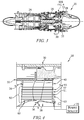
- the illustrative gas turbine engine 20 of each missile 14, 16 includes a compressor assembly 24, a combustor assembly 26, and a turbine assembly 28 as shown in Fig. 3 .
- the compressor assembly 24 compresses and delivers air to the combustor assembly 26.
- the combustor assembly 26 mixes fuel with the compressed air received from the compressor assembly 24 and ignites the fuel.
- the hot high pressure products of the combustion reaction in the combustor assembly 26 are directed into the turbine assembly 28 and the turbine assembly 28 extracts work to drive the compressor assembly 24 and exhausts thrust to propel the engine 20 as suggested in Fig. 3 .
- the turbine assembly 28 illustratively includes a case 30 with a support housing 32, and a plurality of vanes 34 coupled to the support housing 32, as shown in Figs. 3 and 4 .
- a rotor 36 may be mounted in the case 30 to rotate relative to the case 30 and includes a wheel 38 and a plurality of blades 40.
- the vanes 34 of the case 30 may extend across the flow path of the hot, high-pressure combustion products from the combustor assembly 26 to direct the combustion products toward the blades 40 of the rotor 36.
- the blades 40 may in turn be pushed by the combustion products to cause the rotor 36 to rotate and thereby drive the rotating components of the compressor assembly 24.
- the illustrative turbine assembly 28 includes a fuse 50 that provides a rotor system lock adapted to block unintended rotation (or windmilling) of components in the gas turbine engine 20 as suggested in Fig. 4 .
- the illustrative fuse 50 extends from at least one of the plurality of vanes 34 included in the case 30 to at least one blade 40 included in the rotor 36, as shown in Fig. 4 .
- the fuse 50 may include a plurality of wraps 51, 52 spaced circumferentially from one another that each extend around one or more vanes 34 and one or more blades 40 in order to block rotation of the rotor 36 relative to the case when air flows over the blades when the engine is not in operation, for example, when the engine 20 is ferried in a missile 14, 16 by the aircraft 10.
- the number of wraps 51, 52 included in the fuse will be dependent on the operating conditions of the gas turbine engine 20, and should be sufficient to block rotation of the rotor 36 relative to the case 30 during periods when the gas turbine engine 20 is experiencing conditions that may cause unintentional rotation or windmilling.
- the fuse 50 may also reduce the potential for foreign object damage (FOD) to the gas turbine engine 20 before or after release of the illustrative missiles 14, 16 from the aircraft 10.
- the fuse 50 may extend from other rotating components in the engine 20 to other static components in the engine 20 to block unintended rotation.
- the fuse 50 may extend around or between compressor vanes and compressor blades; between sump housings and rotor shafts; or between any other suitable combination of static and dynamic structure within the engine 20.
- the fuse 50 may be shaped and/or manufactured in various forms other than into wraps 51, 52 to engage components of the engine 20.
- the fuse 50 may form one or more hooks, welds, buttons, or other connection features to engage components of the engine 20.
- each wrap 51, 52 includes a metallic wire 60 that forms a plurality of loops 61, 62, 63 as shown in Fig. 4 .
- the metallic wire 60 is made from a eutectic tin-based alloy adapted to melt in response to the application of an electrical current.
- the wire 60 may be made from other suitable materials.
- each wrap 51, 52 may include a textile band. The textile band may be made from a carbon-fiber material or another suitable material adapted to burn or break down in response to the application of an electrical current.
- the turbine assembly 20 also includes an electrical power source 70 as shown diagrammatically in Fig. 4 .
- the power source 70 is coupled to the fuse 50 and is configured to apply a predetermined current to the fuse 50.
- the fuse 50 disintegrates (melts, burns, or otherwise breaks down to a weakened or broken state) to free the blades 40 from the vanes 34 and allow the rotor 36 to move relative to the case 30.
- the electrical power source 70 may be a generator, a capacitor, or a battery adapted to apply 20 amps or less to the fuse 50.
- the power source 70 is configured to provide a predetermined electrical current to the fuse during engine start-up so that the gas turbine engine may operate normally upon release of a missile 14, 16 from the aircraft 10, or in response to a use input.
- the predetermined electrical current sufficient to cause the fuse to disintegrate may illustratively be 1 to 50 amperes.
- a method 110 of making a turbine assembly includes a step 112 of mounting a turbine rotor in a turbine case for rotation relative to the turbine case, followed by a step 114 of fashioning a fuse between corresponding blades included in the turbine rotor and vanes included in the turbine case.
- the method also includes a step 116 of coupling the fuse to an electrical power source.
- the step 114 of fashioning a fuse may include a step 118 of winding a first wrap around a first corresponding blade and vane as shown in Fig. 5 .
- the step 114 may also include a step 120 of winding additional wraps around additional vanes and blades as necessary.
Landscapes
- Engineering & Computer Science (AREA)
- General Engineering & Computer Science (AREA)
- Mechanical Engineering (AREA)
- Chemical & Material Sciences (AREA)
- Combustion & Propulsion (AREA)
- Aviation & Aerospace Engineering (AREA)
- Turbine Rotor Nozzle Sealing (AREA)
Claims (15)
- Turbinenbaugruppe (28) zum Einsatz in einem Gasturbinenmotor (20), wobei die Baugruppe umfasst:ein Gehäuse (30), das ein Stützgehäuse (32) und eine Mehrzahl von Flügelschaufeln (34) aufweist, die mit dem Stützgehäuse (32) gekoppelt sind,ein Rotor (36), der in dem Gehäuse (30) gelagert ist, um relativ zum Gehäuse (30) zu rotieren, wobei der Rotor (36) ein Rad (38) und eine Mehrzahl von Schaufeln (40) aufweist, die mit dem Rad (38) gekoppelt sind,dadurch gekennzeichnet, dass die Baugruppe umfasst:eine Sicherung (50), die sich von mindestens einer Flügelschaufel (34), die in dem Gehäuse (30) aufgenommen ist, bis zu mindestens einer Schaufel (40), die in dem Rotor (36) aufgenommen ist, erstreckt, um ein Rotieren des Rotors (36) relativ zum Gehäuse (30) zu blockieren, und die in Reaktion auf das Anlegen eines vorbestimmten Stroms auslöst, so dass der Rotor (36) relativ zum Gehäuse (30) rotieren kann, undeine elektrische Energiequelle (70), die mit der Sicherung (50) verbunden ist, um den vorbestimmten Strom der Sicherung (50) bereitzustellen.
- Turbinenbaugruppe (28) zum Einsatz in einem Gasturbinenmotor (20), wobei die Baugruppe umfasst:ein Gehäuse (30), das ein Stützgehäuse (32) und eine Mehrzahl von Flügelschaufeln (34) aufweist, die mit dem Stützgehäuse (32) gekoppelt sind,ein Rotor (36), der in dem Gehäuse (30) gelagert ist, um relativ zum Gehäuse (30) zu rotieren, wobei der Rotor (36) ein Rad (38) und eine Mehrzahl von Schaufeln (40) aufweist, die mit dem Rad (38) gekoppelt sind,dadurch gekennzeichnet, dass die Baugruppe umfasst:eine Sicherung (50), die sich von dem Gehäuse (30) bis zum Rotor (36) erstreckt, um ein Rotieren des Rotors (36) relativ zum Gehäuse (30) zu blockieren, und die in Reaktion auf das Anlegen eines vorbestimmten Stroms auslöst, so dass der Rotor (36) relativ zum Gehäuse (30) rotieren kann, undeine elektrische Energiequelle (70), die mit der Sicherung (50) verbunden ist, um den vorbestimmten Strom der Sicherung (50) bereitzustellen.
- Turbinenbaugruppe (28) zum Einsatz in einem Gasturbinenmotor (20), wobei die Baugruppe umfasst:ein Gehäuse (30), das ein Stützgehäuse (32) und eine Mehrzahl von Flügelschaufeln (34) aufweist, die mit dem Stützgehäuse (32) gekoppelt sind,ein Rotor (36), der in dem Gehäuse (30) gelagert ist, um relativ zum Gehäuse (30) zu rotieren, wobei der Rotor (36) ein Rad (38) und eine Mehrzahl von Schaufeln (40) aufweist, die mit dem Rad (38) gekoppelt sind,dadurch gekennzeichnet, dass die Baugruppe umfasst:eine Sicherung (50), die sich von mindestens einer Flügelschaufel (34), die in dem Gehäuse (30) aufgenommen ist, bis zu mindestens einer Schaufel (40), die in dem Rotor (36) aufgenommen ist, erstreckt, und die sich von dem Gehäuse (30) bis zu dem Rotor (36) erstreckt, um ein Rotieren des Rotors (36) relativ zum Gehäuse (30) zu blockieren, und die in Reaktion auf das Anlegen eines vorbestimmten Stroms auslöst, so dass der Rotor (36) relativ zum Gehäuse (30) rotieren kann, undeine elektrische Energiequelle (70), die mit der Sicherung (50) verbunden ist, um den vorbestimmten Strom der Sicherung (50) bereitzustellen.
- Turbinenbaugruppe (28) nach Anspruch 1, 2 oder 3, wobei die Sicherung (50) eine erste Umwicklung (51) umfasst, die sich um mindestens eine Flügelschaufel (34) und/oder eine erste Komponente erstreckt, die in dem Gehäuse (30) aufgenommen ist, und mindestens eine Schaufel (40) und/oder eine erste Komponente, die in dem Rotor (36) aufgenommen ist.
- Turbinenbaugruppe (28) nach Anspruch 4, wobei die Sicherung (50) eine zweite Umwicklung (52) umfasst, die umlaufend von der ersten Umwicklung (51) beabstandet ist, wobei sich die zweite Umwicklung (52) um mindestens eine Flügelschaufel (34) und/oder eine zweite Komponente, die in dem Gehäuse (30) aufgenommen ist, und mindestens eine Schaufel (40) und/oder eine zweite Komponente, die in dem Rotor (36) aufgenommen ist, erstreckt.
- Turbinenbaugruppe (28) nach einem der vorhergehenden Ansprüche, wobei die Sicherung (50) einen Metalldraht (60) umfasst.
- Turbinenbaugruppe (28) nach Anspruch 6, wobei der Metalldraht (60) eine zinnbasierte Legierung umfasst.
- Turbinenbaugruppe (28) nach einem der vorhergehenden Ansprüche, wobei die Sicherung (50) ein Textilband umfasst.
- Turbinenbaugruppe (28) nach Anspruch 8, wobei das Textilband eine Kohlenstofffaser umfasst.
- Turbinenbaugruppe (28) nach einem der vorhergehenden Ansprüche, wobei der vorbestimmte Strom weniger als 20 Ampere beträgt.
- Turbinenbaugruppe (28) nach Anspruch 1, 2 oder 3, wobei die elektrische Energiequelle (70) unter einem Generator, einem Kondensator, und einer Batterie ausgewählt wird.
- Turbinenbaugruppe (28) nach Anspruch 6, wobei sich der Metalldraht (60) um eine erste Flügelschaufel und eine erste Schaufel erstreckt, um eine erste Umwickelung (51) bereitzustellen und ein zweiter Metalldraht (60) sich um eine zweite Flügelschaufel und eine zweite Schaufel erstreckt, um eine zweite Umwickelung (52) bereitzustellen.
- Turbinenbaugruppe (28) nach einem Anspruch 8, wobei sich das Textilband um eine erste Flügelschaufel (34) und eine erste Schaufel erstreckt, um die erste Umwicklung (51) bereitzustellen und ein zweites Textilband, das sich um eine zweite Flügelschaufel (34) und eine zweite Schaufel erstreckt, um die zweite Umwicklung (52) bereitzustellen.
- Verfahren zur Herstellung einer Turbinenbaugruppe (28), wobei das Verfahren umfasst
Lagern eines Rotors (36) in einem Gehäuse (30) zum Rotieren relativ zu dem Gehäuse (30), gekennzeichnet durch:Erstellen einer Sicherung (50) zwischen mindestens einer Schaufel (40), die in dem Rotor (36) aufgenommen ist, und mindestens einer Flügelschaufel (34), die in dem Gehäuse (30) aufgenommen ist, um eine Rotation des Rotors (36) relativ zum Gehäuse (30) zu blockieren,wobei die Sicherung (50) von einem Material hergestellt ist, das in Reaktion auf das Anlegen eines vorbestimmten Stroms auslöst, so dass der Rotor (36) relativ zu dem Gehäuse (30) rotieren kann,wobei das Verfahren darüber hinaus umfasst, eine elektrische Energiequelle (70) mit der Sicherung (50) zu verbinden, um der Sicherung (50) den vorbestimmten Strom bereitzustellen. - Verfahren nach Anspruch 14, wobei der vorbestimmte Strom weniger als 20 Ampere beträgt.
Applications Claiming Priority (1)
| Application Number | Priority Date | Filing Date | Title |
|---|---|---|---|
| US201562113813P | 2015-02-09 | 2015-02-09 |
Publications (2)
| Publication Number | Publication Date |
|---|---|
| EP3054107A1 EP3054107A1 (de) | 2016-08-10 |
| EP3054107B1 true EP3054107B1 (de) | 2017-12-06 |
Family
ID=55300432
Family Applications (1)
| Application Number | Title | Priority Date | Filing Date |
|---|---|---|---|
| EP16154368.1A Active EP3054107B1 (de) | 2015-02-09 | 2016-02-05 | Turbinenanordnung mit einer sperreinrichtung des rotorsystems |
Country Status (2)
| Country | Link |
|---|---|
| US (1) | US10267177B2 (de) |
| EP (1) | EP3054107B1 (de) |
Families Citing this family (1)
| Publication number | Priority date | Publication date | Assignee | Title |
|---|---|---|---|---|
| GB201419859D0 (en) * | 2014-11-07 | 2014-12-24 | Rolls Royce Plc | No title listed |
Family Cites Families (13)
| Publication number | Priority date | Publication date | Assignee | Title |
|---|---|---|---|---|
| US2982093A (en) * | 1957-08-30 | 1961-05-02 | Napier & Son Ltd | Compound ram jet turbo-rocket engines |
| US3779665A (en) | 1972-09-22 | 1973-12-18 | Gen Electric | Combined variable angle stator and windmill control system |
| GB1594354A (en) * | 1977-06-02 | 1981-07-30 | Rolls Royce | Device for turning the rotor of a gas turbine engine |
| US4664539A (en) | 1986-02-13 | 1987-05-12 | Florida State University | Serial safety bearing |
| US5660357A (en) * | 1995-07-24 | 1997-08-26 | Northrop Grumman Corporation | Airstream ejected missile engine inlet cover |
| FR2761733B1 (fr) | 1997-04-03 | 1999-06-11 | Hispano Suiza Sa | Inverseur de poussee pour turbomoteur d'aeronef |
| FR2856430B1 (fr) | 2003-06-20 | 2005-09-23 | Snecma Moteurs | Agencement de supports de paliers pour arbre tournant d'un moteur d'aeronef et moteur d'aeronef equipe d'un tel agencement |
| US7097413B2 (en) | 2004-05-12 | 2006-08-29 | United Technologies Corporation | Bearing support |
| US7225607B2 (en) * | 2004-08-27 | 2007-06-05 | Pratt & Whitney Canada Corp. | Gas turbine braking apparatus and method |
| US7621117B2 (en) | 2006-06-19 | 2009-11-24 | Pratt & Whitney Canada Corp. | Apparatus and method for controlling engine windmilling |
| US20100047077A1 (en) * | 2007-12-28 | 2010-02-25 | General Electric Company | Ferry Flight Engine Fairing Kit |
| FR2966208B1 (fr) | 2010-10-13 | 2012-12-28 | Snecma | Boitier de liaison entre un arbre d'entrainement de soufflante de moteur et un palier de roulement |
| US8814512B2 (en) * | 2011-07-05 | 2014-08-26 | United Technologies Corporation | Fan disk apparatus and method |
-
2016
- 2016-02-05 EP EP16154368.1A patent/EP3054107B1/de active Active
- 2016-02-05 US US15/016,813 patent/US10267177B2/en active Active
Non-Patent Citations (1)
| Title |
|---|
| DR W GÄRTNER: "RB199, technologischer Spitzenreiter seiner Zeit", OKTOBER, 22 October 2014 (2014-10-22), XP055384288, Retrieved from the Internet <URL:http://www.dglr.de/fileadmin/inhalte/dglr/fb/q3/veranstaltungen/Q3_2014_40_Jahre_Tornado/4_Gaertner-RB199_technologischer_Spitzenreiter_seiner_Zeit.pdf> [retrieved on 20170622] * |
Also Published As
| Publication number | Publication date |
|---|---|
| US10267177B2 (en) | 2019-04-23 |
| EP3054107A1 (de) | 2016-08-10 |
| US20160230587A1 (en) | 2016-08-11 |
Similar Documents
| Publication | Publication Date | Title |
|---|---|---|
| EP3205840B1 (de) | Rotorlagerungssystem für eine gasturbine mit formgedächtnislegierungskomponente | |
| EP3862542B1 (de) | Kühlsystem für stromkabel in einem gasturbinenmotor | |
| CN106337739B (zh) | 用于支撑燃气涡轮发动机的转子轴的轴承组件 | |
| EP2415991B1 (de) | Kupplung zwischen getriebe und starter-generator eines turbofan triebwerks | |
| US10823078B2 (en) | Systems and methods for starting a turbine engine | |
| EP3453840B1 (de) | Aktives spaltkontrollsystem eines gasturbinenmotors unter verwendung eines einlasspartikelscheiders | |
| US8376700B2 (en) | Compressed air starter for turbomachine | |
| US20090205341A1 (en) | Gas turbine engine with twin towershaft accessory gearbox | |
| EP2938857B1 (de) | Hitzeschild zur kühlung einer strebe | |
| US10287919B2 (en) | Liner lock segment | |
| US9951694B2 (en) | System and method for emergency starting of an aircraft turbomachine | |
| US9863261B2 (en) | Component retention with probe | |
| EP3375983B1 (de) | Dichtungspaneel für einen gasturbinenmotor | |
| CA2624645A1 (en) | Blade attachment retention device | |
| US20140245750A1 (en) | Circumferentially retained fairing | |
| EP3284943B1 (de) | Verzweigte gasgeneratorabgasleitung an eine freie turbine | |
| US20200240720A1 (en) | Gas turbine engine having a heat absorption device and an associated method thereof | |
| US20180347463A1 (en) | Gas turbine engine de-icing system | |
| EP3054107B1 (de) | Turbinenanordnung mit einer sperreinrichtung des rotorsystems | |
| EP2546460A2 (de) | Turbinenmotor und Lastreduktionsvorrichtung dafür | |
| US20200248564A1 (en) | Turbine vane assembly with ceramic matrix composite vanes | |
| CA2955385A1 (en) | Spline seal for a gas turbine engine | |
| US9140138B2 (en) | Turbomachine containment structure | |
| EP3019724B1 (de) | Vorgeladener hinterer entlüftungsbereich für ein niederdruck-lüftungsgebläse | |
| EP3170990B1 (de) | Äussere luftdichtung für gasturbinenmotor |
Legal Events
| Date | Code | Title | Description |
|---|---|---|---|
| PUAI | Public reference made under article 153(3) epc to a published international application that has entered the european phase |
Free format text: ORIGINAL CODE: 0009012 |
|
| AK | Designated contracting states |
Kind code of ref document: A1 Designated state(s): AL AT BE BG CH CY CZ DE DK EE ES FI FR GB GR HR HU IE IS IT LI LT LU LV MC MK MT NL NO PL PT RO RS SE SI SK SM TR |
|
| AX | Request for extension of the european patent |
Extension state: BA ME |
|
| 17P | Request for examination filed |
Effective date: 20170206 |
|
| RBV | Designated contracting states (corrected) |
Designated state(s): AL AT BE BG CH CY CZ DE DK EE ES FI FR GB GR HR HU IE IS IT LI LT LU LV MC MK MT NL NO PL PT RO RS SE SI SK SM TR |
|
| GRAP | Despatch of communication of intention to grant a patent |
Free format text: ORIGINAL CODE: EPIDOSNIGR1 |
|
| INTG | Intention to grant announced |
Effective date: 20170712 |
|
| GRAS | Grant fee paid |
Free format text: ORIGINAL CODE: EPIDOSNIGR3 |
|
| GRAA | (expected) grant |
Free format text: ORIGINAL CODE: 0009210 |
|
| AK | Designated contracting states |
Kind code of ref document: B1 Designated state(s): AL AT BE BG CH CY CZ DE DK EE ES FI FR GB GR HR HU IE IS IT LI LT LU LV MC MK MT NL NO PL PT RO RS SE SI SK SM TR |
|
| REG | Reference to a national code |
Ref country code: GB Ref legal event code: FG4D |
|
| REG | Reference to a national code |
Ref country code: AT Ref legal event code: REF Ref document number: 952580 Country of ref document: AT Kind code of ref document: T Effective date: 20171215 Ref country code: CH Ref legal event code: EP |
|
| REG | Reference to a national code |
Ref country code: IE Ref legal event code: FG4D |
|
| REG | Reference to a national code |
Ref country code: DE Ref legal event code: R096 Ref document number: 602016000980 Country of ref document: DE |
|
| REG | Reference to a national code |
Ref country code: FR Ref legal event code: PLFP Year of fee payment: 3 |
|
| REG | Reference to a national code |
Ref country code: NL Ref legal event code: MP Effective date: 20171206 |
|
| REG | Reference to a national code |
Ref country code: LT Ref legal event code: MG4D |
|
| PG25 | Lapsed in a contracting state [announced via postgrant information from national office to epo] |
Ref country code: LT Free format text: LAPSE BECAUSE OF FAILURE TO SUBMIT A TRANSLATION OF THE DESCRIPTION OR TO PAY THE FEE WITHIN THE PRESCRIBED TIME-LIMIT Effective date: 20171206 Ref country code: NO Free format text: LAPSE BECAUSE OF FAILURE TO SUBMIT A TRANSLATION OF THE DESCRIPTION OR TO PAY THE FEE WITHIN THE PRESCRIBED TIME-LIMIT Effective date: 20180306 Ref country code: ES Free format text: LAPSE BECAUSE OF FAILURE TO SUBMIT A TRANSLATION OF THE DESCRIPTION OR TO PAY THE FEE WITHIN THE PRESCRIBED TIME-LIMIT Effective date: 20171206 Ref country code: FI Free format text: LAPSE BECAUSE OF FAILURE TO SUBMIT A TRANSLATION OF THE DESCRIPTION OR TO PAY THE FEE WITHIN THE PRESCRIBED TIME-LIMIT Effective date: 20171206 Ref country code: SE Free format text: LAPSE BECAUSE OF FAILURE TO SUBMIT A TRANSLATION OF THE DESCRIPTION OR TO PAY THE FEE WITHIN THE PRESCRIBED TIME-LIMIT Effective date: 20171206 |
|
| REG | Reference to a national code |
Ref country code: AT Ref legal event code: MK05 Ref document number: 952580 Country of ref document: AT Kind code of ref document: T Effective date: 20171206 |
|
| PG25 | Lapsed in a contracting state [announced via postgrant information from national office to epo] |
Ref country code: GR Free format text: LAPSE BECAUSE OF FAILURE TO SUBMIT A TRANSLATION OF THE DESCRIPTION OR TO PAY THE FEE WITHIN THE PRESCRIBED TIME-LIMIT Effective date: 20180307 Ref country code: LV Free format text: LAPSE BECAUSE OF FAILURE TO SUBMIT A TRANSLATION OF THE DESCRIPTION OR TO PAY THE FEE WITHIN THE PRESCRIBED TIME-LIMIT Effective date: 20171206 Ref country code: RS Free format text: LAPSE BECAUSE OF FAILURE TO SUBMIT A TRANSLATION OF THE DESCRIPTION OR TO PAY THE FEE WITHIN THE PRESCRIBED TIME-LIMIT Effective date: 20171206 Ref country code: HR Free format text: LAPSE BECAUSE OF FAILURE TO SUBMIT A TRANSLATION OF THE DESCRIPTION OR TO PAY THE FEE WITHIN THE PRESCRIBED TIME-LIMIT Effective date: 20171206 Ref country code: BG Free format text: LAPSE BECAUSE OF FAILURE TO SUBMIT A TRANSLATION OF THE DESCRIPTION OR TO PAY THE FEE WITHIN THE PRESCRIBED TIME-LIMIT Effective date: 20180306 |
|
| PG25 | Lapsed in a contracting state [announced via postgrant information from national office to epo] |
Ref country code: NL Free format text: LAPSE BECAUSE OF FAILURE TO SUBMIT A TRANSLATION OF THE DESCRIPTION OR TO PAY THE FEE WITHIN THE PRESCRIBED TIME-LIMIT Effective date: 20171206 |
|
| PG25 | Lapsed in a contracting state [announced via postgrant information from national office to epo] |
Ref country code: EE Free format text: LAPSE BECAUSE OF FAILURE TO SUBMIT A TRANSLATION OF THE DESCRIPTION OR TO PAY THE FEE WITHIN THE PRESCRIBED TIME-LIMIT Effective date: 20171206 Ref country code: CZ Free format text: LAPSE BECAUSE OF FAILURE TO SUBMIT A TRANSLATION OF THE DESCRIPTION OR TO PAY THE FEE WITHIN THE PRESCRIBED TIME-LIMIT Effective date: 20171206 Ref country code: SK Free format text: LAPSE BECAUSE OF FAILURE TO SUBMIT A TRANSLATION OF THE DESCRIPTION OR TO PAY THE FEE WITHIN THE PRESCRIBED TIME-LIMIT Effective date: 20171206 |
|
| PG25 | Lapsed in a contracting state [announced via postgrant information from national office to epo] |
Ref country code: AT Free format text: LAPSE BECAUSE OF FAILURE TO SUBMIT A TRANSLATION OF THE DESCRIPTION OR TO PAY THE FEE WITHIN THE PRESCRIBED TIME-LIMIT Effective date: 20171206 Ref country code: PL Free format text: LAPSE BECAUSE OF FAILURE TO SUBMIT A TRANSLATION OF THE DESCRIPTION OR TO PAY THE FEE WITHIN THE PRESCRIBED TIME-LIMIT Effective date: 20171206 Ref country code: SM Free format text: LAPSE BECAUSE OF FAILURE TO SUBMIT A TRANSLATION OF THE DESCRIPTION OR TO PAY THE FEE WITHIN THE PRESCRIBED TIME-LIMIT Effective date: 20171206 Ref country code: IT Free format text: LAPSE BECAUSE OF FAILURE TO SUBMIT A TRANSLATION OF THE DESCRIPTION OR TO PAY THE FEE WITHIN THE PRESCRIBED TIME-LIMIT Effective date: 20171206 Ref country code: RO Free format text: LAPSE BECAUSE OF FAILURE TO SUBMIT A TRANSLATION OF THE DESCRIPTION OR TO PAY THE FEE WITHIN THE PRESCRIBED TIME-LIMIT Effective date: 20171206 |
|
| REG | Reference to a national code |
Ref country code: DE Ref legal event code: R119 Ref document number: 602016000980 Country of ref document: DE |
|
| PG25 | Lapsed in a contracting state [announced via postgrant information from national office to epo] |
Ref country code: MC Free format text: LAPSE BECAUSE OF FAILURE TO SUBMIT A TRANSLATION OF THE DESCRIPTION OR TO PAY THE FEE WITHIN THE PRESCRIBED TIME-LIMIT Effective date: 20171206 |
|
| PLBE | No opposition filed within time limit |
Free format text: ORIGINAL CODE: 0009261 |
|
| STAA | Information on the status of an ep patent application or granted ep patent |
Free format text: STATUS: NO OPPOSITION FILED WITHIN TIME LIMIT |
|
| 26N | No opposition filed |
Effective date: 20180907 |
|
| REG | Reference to a national code |
Ref country code: IE Ref legal event code: MM4A |
|
| REG | Reference to a national code |
Ref country code: BE Ref legal event code: MM Effective date: 20180228 |
|
| PG25 | Lapsed in a contracting state [announced via postgrant information from national office to epo] |
Ref country code: LU Free format text: LAPSE BECAUSE OF NON-PAYMENT OF DUE FEES Effective date: 20180205 Ref country code: DK Free format text: LAPSE BECAUSE OF FAILURE TO SUBMIT A TRANSLATION OF THE DESCRIPTION OR TO PAY THE FEE WITHIN THE PRESCRIBED TIME-LIMIT Effective date: 20171206 Ref country code: SI Free format text: LAPSE BECAUSE OF FAILURE TO SUBMIT A TRANSLATION OF THE DESCRIPTION OR TO PAY THE FEE WITHIN THE PRESCRIBED TIME-LIMIT Effective date: 20171206 |
|
| PG25 | Lapsed in a contracting state [announced via postgrant information from national office to epo] |
Ref country code: DE Free format text: LAPSE BECAUSE OF NON-PAYMENT OF DUE FEES Effective date: 20180901 Ref country code: IE Free format text: LAPSE BECAUSE OF NON-PAYMENT OF DUE FEES Effective date: 20180205 |
|
| PG25 | Lapsed in a contracting state [announced via postgrant information from national office to epo] |
Ref country code: BE Free format text: LAPSE BECAUSE OF NON-PAYMENT OF DUE FEES Effective date: 20180228 |
|
| REG | Reference to a national code |
Ref country code: CH Ref legal event code: PL |
|
| PG25 | Lapsed in a contracting state [announced via postgrant information from national office to epo] |
Ref country code: LI Free format text: LAPSE BECAUSE OF NON-PAYMENT OF DUE FEES Effective date: 20190228 Ref country code: CH Free format text: LAPSE BECAUSE OF NON-PAYMENT OF DUE FEES Effective date: 20190228 |
|
| PG25 | Lapsed in a contracting state [announced via postgrant information from national office to epo] |
Ref country code: MT Free format text: LAPSE BECAUSE OF NON-PAYMENT OF DUE FEES Effective date: 20180205 |
|
| PG25 | Lapsed in a contracting state [announced via postgrant information from national office to epo] |
Ref country code: TR Free format text: LAPSE BECAUSE OF FAILURE TO SUBMIT A TRANSLATION OF THE DESCRIPTION OR TO PAY THE FEE WITHIN THE PRESCRIBED TIME-LIMIT Effective date: 20171206 |
|
| PG25 | Lapsed in a contracting state [announced via postgrant information from national office to epo] |
Ref country code: PT Free format text: LAPSE BECAUSE OF FAILURE TO SUBMIT A TRANSLATION OF THE DESCRIPTION OR TO PAY THE FEE WITHIN THE PRESCRIBED TIME-LIMIT Effective date: 20171206 |
|
| PG25 | Lapsed in a contracting state [announced via postgrant information from national office to epo] |
Ref country code: CY Free format text: LAPSE BECAUSE OF FAILURE TO SUBMIT A TRANSLATION OF THE DESCRIPTION OR TO PAY THE FEE WITHIN THE PRESCRIBED TIME-LIMIT Effective date: 20171206 Ref country code: MK Free format text: LAPSE BECAUSE OF NON-PAYMENT OF DUE FEES Effective date: 20171206 Ref country code: HU Free format text: LAPSE BECAUSE OF FAILURE TO SUBMIT A TRANSLATION OF THE DESCRIPTION OR TO PAY THE FEE WITHIN THE PRESCRIBED TIME-LIMIT; INVALID AB INITIO Effective date: 20160205 |
|
| PG25 | Lapsed in a contracting state [announced via postgrant information from national office to epo] |
Ref country code: AL Free format text: LAPSE BECAUSE OF FAILURE TO SUBMIT A TRANSLATION OF THE DESCRIPTION OR TO PAY THE FEE WITHIN THE PRESCRIBED TIME-LIMIT Effective date: 20171206 Ref country code: IS Free format text: LAPSE BECAUSE OF FAILURE TO SUBMIT A TRANSLATION OF THE DESCRIPTION OR TO PAY THE FEE WITHIN THE PRESCRIBED TIME-LIMIT Effective date: 20180406 |
|
| GBPC | Gb: european patent ceased through non-payment of renewal fee |
Effective date: 20200205 |
|
| PG25 | Lapsed in a contracting state [announced via postgrant information from national office to epo] |
Ref country code: GB Free format text: LAPSE BECAUSE OF NON-PAYMENT OF DUE FEES Effective date: 20200205 |
|
| P01 | Opt-out of the competence of the unified patent court (upc) registered |
Effective date: 20230528 |
|
| PGFP | Annual fee paid to national office [announced via postgrant information from national office to epo] |
Ref country code: FR Payment date: 20260224 Year of fee payment: 11 |