EP3054178A1 - Plaque d'aspiration et dispositif de plaque d'aspiration ayant une plaque d'aspiration - Google Patents
Plaque d'aspiration et dispositif de plaque d'aspiration ayant une plaque d'aspiration Download PDFInfo
- Publication number
- EP3054178A1 EP3054178A1 EP14849965.0A EP14849965A EP3054178A1 EP 3054178 A1 EP3054178 A1 EP 3054178A1 EP 14849965 A EP14849965 A EP 14849965A EP 3054178 A1 EP3054178 A1 EP 3054178A1
- Authority
- EP
- European Patent Office
- Prior art keywords
- main body
- suction
- suction cup
- supporting
- plate
- Prior art date
- Legal status (The legal status is an assumption and is not a legal conclusion. Google has not performed a legal analysis and makes no representation as to the accuracy of the status listed.)
- Withdrawn
Links
Images


Classifications
-
- F—MECHANICAL ENGINEERING; LIGHTING; HEATING; WEAPONS; BLASTING
- F16—ENGINEERING ELEMENTS AND UNITS; GENERAL MEASURES FOR PRODUCING AND MAINTAINING EFFECTIVE FUNCTIONING OF MACHINES OR INSTALLATIONS; THERMAL INSULATION IN GENERAL
- F16B—DEVICES FOR FASTENING OR SECURING CONSTRUCTIONAL ELEMENTS OR MACHINE PARTS TOGETHER, e.g. NAILS, BOLTS, CIRCLIPS, CLAMPS, CLIPS OR WEDGES; JOINTS OR JOINTING
- F16B47/00—Suction cups for attaching purposes; Equivalent means using adhesives
Definitions
- the present application relates to the technical filed of suction cups, in particular to a suction cup having a simple structure and a strong suction force and a suction cup device having the suction cup.
- Common hanging media include a hook and a suction cup structure.
- the hook has a bonding layer on the back and uses the bonding layer to bond with the surface of the wall or the object.
- the hook has a big bonding force, and when the hook is removed, marks of binders will be left on the surface of the wall or the object.
- the suction cup structure uses extrusion to form a vacuum, to realize the suction effect. A suction force of the suction cup structure is stronger than that of the hook and will not leave marks on the surface of the wall or the object.
- most of the suction cup structures have complicated structures, which may cause a high manufacturing cost and inconvenience to the users.
- a technical issue to be solved in the art is to improve the conventional technology to provide a suction cup which can have a strong suction force with a simple structure and have a strong suction force when being used in the suction cup structure.
- an object of the present application is to provide a suction cup which can be applied in a suction cup device to allow the suction cup device to realize a strong suction force with a simple structure. Based on this, a suction cup device is further provided by the present application.
- a suction cup includes a main body made of flexible material and having a disk shape, and a supporting and connecting assembly connected to the main body and made of hard material.
- a side wall of the supporting and connecting assembly is provided with external threads, an edge of the main body is provided with a first suction structure, a side of a longitudinal section of the first suction structure is of a stepped shape having at least three levels of steps, and a top of the first suction structure is higher than a center area of a top of the main body.
- the supporting and connecting assembly includes a supporting seat and a supporting rod which are connected together, the supporting seat is sealed in the main body, the supporting rod extends upwardly to an outside of the main body, and the external threads are provided on a side wall of the supporting rod.
- the center area of the top of the main body is provided with a boss and an annular groove surrounding the boss, and the supporting rod runs through the boss and extends outwards to the outside of the main body.
- a suction cup device includes a suction cup, a tightening cap and a switching knob.
- the suction cup includes a main body made of flexible material and having a disk shape, and a supporting and connecting assembly connected to the main body and made of hard material.
- a side wall of the supporting and connecting assembly is provided with external threads, an edge of the main body is provided with a first suction structure, a side of a longitudinal section of the first suction structure is of a stepped shape having at least three levels of steps, and a top of the first suction structure is higher than a center area of a top of the main body.
- the tightening cap is made of flexible material and includes a cap plate and a side plate surrounding an edge of the cap plate and extending downward.
- the side plate is provided with a second suction structure configured to cooperate with the first suction structure of the suction cup.
- the switching knob is located on the tightening cap, a lower portion of the switching knob is provided with a threaded hole, internal threads configured to cooperate with the external threads are provided in the threaded hole, and a partial area at a lower surface of the switching knob is in contact with an upper surface of the tightening cap.
- the switching knob includes a top plate and a side coaming provided at an edge of the top plate, a lower surface of the top plate is provided with a connecting column, the threaded hole is provided in the connecting column in a direction of a longitudinal axis of the connecting column, an outer side wall of the connecting column is provided with a supporting sleeve, a lower surface of the supporting sleeve is in contact with an upper surface of the tightening cap, and a lower surface of the side coaming is in contact with the upper surface of the tightening cap.
- the cap plate of the tightening cap is provided with a through hole, and the connecting column runs through the through hole.
- a lower surface of the cap plate of the tightening cap is provided with a protrusion portion, and the through hole runs through the protrusion portion.
- the supporting and connecting assembly includes a supporting seat and a supporting rod which are connected together, the supporting seat is sealed in the main body, the supporting rod extends upwardly to an outside of the main body and extends into the threaded hole, and the external threads are provided on a side wall of the supporting rod.
- the center area of the top of the main body is provided with a boss and an annular groove surrounding the boss, and the supporting rod runs through the boss and extends outwards to the outside of the main body.
- the side plate of the tightening cap has one end connected to the cap plate and another end inclining downward and outward
- the second suction structure is provided at a lower end of the side plate
- an outer side surface of the second suction structure expands outward from an outer side surface of an upper portion of the side plate
- a pressing strip protruding downward is provided on an inner side wall of the second suction structure
- the pressing strip is located in an inside of the top of the first suction structure and is in contact with an upper surface of the main body.
- the suction cup in the present application includes a main body made of flexible material and having a disk shape, and a supporting and connecting assembly connected to the main body and made of hard material.
- a side wall of the supporting and connecting assembly is provided with external threads, an edge of the main body is provided with a first suction structure, a side of a longitudinal section of the first suction structure is of a stepped shape having at least three levels of steps, and a top of the first suction structure is higher than a center area of a top of the main body.
- the supporting and connecting assembly is pulled upward by a relevant assembly of the suction cup device, which tightens a center of the suction cup upward and the first suction structure cooperates with the relevant assembly of the suction cup device and is pressed tightly to the relevant assembly of the suction cup device, thereby forming a vacuum and realizing the suction effect.
- the suction cup device has a simple structure, a strong suction force and a reliable suction effect.
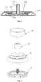
- a suction cup 1 includes a main body 11 of a circular disk shape and a connecting and supporting assembly 12.
- the main body 11 includes an intermediate plate 11a, a first suction structure 11b arranged at an edge of the intermediate plate 11a, a boss 11c arranged at a center area of an upper surface of the intermediate plate 11a, and an annular groove 11d arranged around the boss 11c.
- the connecting and supporting rod 12 includes a supporting seat 12a and a supporting rod 12b which are connected together. A side wall of the supporting rod 12b is provided with external threads.
- the supporting seat 12a is sealed in the intermediate plate 11a, and the supporting rod 12b runs through the boss 11b and extends outwards to the outside.
- the first suction structure 11b is of a structure having three steps, and includes three levels of bosses, and the diameters of the three levels of bosses are reduced progressively from bottom to top.
- a top of the first suction structure 11b is higher than a top of the intermediate plate 11a.
- the main body 11 of the suction cup is made of flexible material, for example plastic, and the connecting and supporting assembly 12 is made of hard material, for example iron.
- the first suction structure has a three-level structure, and in other embodiments, the first suction structure may be provided with more steps, such as having four levels of steps or five levels of steps.
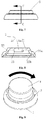
- the suction cup device includes a suction cup 1, a tightening cap 2, a supporting sleeve 3 and a switching knob 4.
- the tightening cap 2 is located on the suction cup 1
- the switching knob 4 is located on the tightening cap 2
- the supporting sleeve 3 is located between the tightening cap 2 and the switching knob 4.
- suction cup 1 The structure of the suction cup 1 can be referred to the foregoing embodiments, which will not be described herein again.
- the tightening cap 2 includes a cap plate 21, and a side plate 22 surrounding an edge of the cap plate 11 and extending downward.
- An upper end of the side plate 22 is connected to the cap plate 21, an upper portion of the side plate 22 inclines outward, a lower portion of the side plate 22 is provided with a second suction structure 22a which is configured to cooperate with the first suction structure.
- An outer side wall of the second suction structure 22a is expanded outward from an outer side wall of the upper portion of the side plate, and an inner side wall of the second suction structure is provided with a pressing strip 22b protruding downward.
- the pressing strip 22b extends into an inside of the first suction structure.
- a protrusion portion 23 is provided in a center area of a lower surface of the cap plate 21, a through hole 21a is further provided in the center area of the cap plate 21, and the through hole 21a runs through the protrusion portion 23.
- the switching knob 4 includes a top plate 41 and a side coaming 42 provided at an edge of the top plate 41.
- a lower surface of the top plate 41 is provided with a connecting column 43, and a threaded hole 43a is provided in the connecting column 43 in a direction of a longitudinal axis of the connecting column 43.
- An upper end of the threaded hole 43a is not in communication with the outside, a lower end of the threaded hole 43a is in communication with the outside, and a supporting rod 12 of the suction cup 1 extends into the threaded hole 43a.
- the supporting sleeve 3 is sleeved on an outer side wall of the connecting column 43, a lower surface of the supporting sleeve 3 is in contact with an upper surface of the tightening cap 2, and a lower surface of the side coaming 42 is in contact with the upper surface of the tightening cap 2.
- the tightening cap 2 is made of flexible material, for example plastic.
- the switching knob 4 is turned right in a direction indicated by an arrow, the supporting rod 12b of the suction cup 1 is pulled, which tightens the center area of the suction cup 1 upward and presses the tightening cap 2 downward in the meantime.
- the suction cup device begins to suck.
- the cooperation intensity between the first and second suction structures are accordingly increased, and the first and second suction structures are bound more tightly, thereby ensuring that a suction surface between the suction cup device and a wall or an object has enough contact area when the suction cup device is in a sucking state, to allow the suction cup device to be hard to fall off.
- the switching knob is continually turned right to continue to pull the center of the suction cup upward, which increases the vacuum degree immediately, thereby increasing the effective suction time of the suction cup device.
- the suction cup device of the present application can conveniently realize vacuum suction with a simple structure, thereby simplifying the manufacture process of the suction cup device and decreasing the cost.
Landscapes
- Engineering & Computer Science (AREA)
- General Engineering & Computer Science (AREA)
- Mechanical Engineering (AREA)
- Hooks, Suction Cups, And Attachment By Adhesive Means (AREA)
Applications Claiming Priority (3)
| Application Number | Priority Date | Filing Date | Title |
|---|---|---|---|
| CN201310460592.0A CN103470613B (zh) | 2013-09-30 | 2013-09-30 | 一种吸附盘及设有此吸附盘的吸盘装置 |
| CN201320614927.5U CN203604411U (zh) | 2013-09-30 | 2013-09-30 | 一种吸附盘及设有此吸附盘的吸盘装置 |
| PCT/CN2014/087639 WO2015043516A1 (fr) | 2013-09-30 | 2014-09-28 | Plaque d'aspiration et dispositif de plaque d'aspiration ayant une plaque d'aspiration |
Publications (2)
| Publication Number | Publication Date |
|---|---|
| EP3054178A1 true EP3054178A1 (fr) | 2016-08-10 |
| EP3054178A4 EP3054178A4 (fr) | 2017-04-05 |
Family
ID=52742086
Family Applications (1)
| Application Number | Title | Priority Date | Filing Date |
|---|---|---|---|
| EP14849965.0A Withdrawn EP3054178A4 (fr) | 2013-09-30 | 2014-09-28 | Plaque d'aspiration et dispositif de plaque d'aspiration ayant une plaque d'aspiration |
Country Status (6)
| Country | Link |
|---|---|
| US (1) | US20160201714A1 (fr) |
| EP (1) | EP3054178A4 (fr) |
| AU (1) | AU2014327933B2 (fr) |
| BR (1) | BR112016004636B1 (fr) |
| RU (1) | RU2643424C2 (fr) |
| WO (1) | WO2015043516A1 (fr) |
Cited By (1)
| Publication number | Priority date | Publication date | Assignee | Title |
|---|---|---|---|---|
| US20150377280A1 (en) * | 2013-02-04 | 2015-12-31 | Katja Pötters | Releasable vacuum holding device |
Families Citing this family (15)
| Publication number | Priority date | Publication date | Assignee | Title |
|---|---|---|---|---|
| US10393168B2 (en) * | 2014-03-07 | 2019-08-27 | Isee Store Innovations, Llc | Securing assembly |
| US10104986B2 (en) * | 2014-03-07 | 2018-10-23 | Isee Store Innovations, L.L.C. | Systems and methods for securing and displaying products |
| US20190203759A1 (en) * | 2017-12-28 | 2019-07-04 | Jacob Zimmerman | Suction Cup Attachment Method For Flexible Materials |
| US11215217B2 (en) | 2018-02-23 | 2022-01-04 | House of Atlas, LLC | Surface mount |
| USD899895S1 (en) | 2018-02-23 | 2020-10-27 | House of Atlas, LLC | Surface mount |
| US10912401B2 (en) * | 2018-09-21 | 2021-02-09 | Isee Store Innovations, L.L.C. | Product displaying holder systems |
| US20200116193A1 (en) * | 2018-10-15 | 2020-04-16 | Aylo Llc | Systems and methods for a suction cup device holder |
| CN110054073B (zh) * | 2019-04-29 | 2023-12-15 | 吉林大学 | 一种凸起式真空吸盘 |
| US12031565B2 (en) | 2020-01-10 | 2024-07-09 | Olson Ip Technologies, Inc. | Suction mount and brackets and accessories therefor |
| USD1005084S1 (en) | 2020-01-21 | 2023-11-21 | Olson Ip Technologies, Inc. | Suction cup mount |
| US11280367B2 (en) | 2020-04-29 | 2022-03-22 | Isee Store Innovations, L.L.C. | Securing assembly having component support hook |
| US11022168B1 (en) | 2020-05-01 | 2021-06-01 | Isee Store Innovations, L.L.C. | Securing assembly having container retaining housing |
| US11673711B2 (en) | 2020-08-03 | 2023-06-13 | Isee Store Innovations, L.L.C. | Fluid container retaining systems and methods |
| USD1019347S1 (en) * | 2022-05-12 | 2024-03-26 | Jiaxing Li | Suction mount |
| CN220687814U (zh) * | 2023-09-07 | 2024-03-29 | 广州精创家居有限公司 | 一种卡扣锁紧的吸盘挂钩 |
Family Cites Families (24)
| Publication number | Priority date | Publication date | Assignee | Title |
|---|---|---|---|---|
| US371281A (en) * | 1887-10-11 | Stefan siemang | ||
| US2047658A (en) * | 1935-12-27 | 1936-07-14 | Zaiger Louis | Suction cup |
| DE2553486A1 (de) * | 1975-11-28 | 1977-06-16 | Ever Clean Gmbh | Vibrationsdaempfer fuer windschutzscheiben |
| US5516019A (en) * | 1994-05-16 | 1996-05-14 | Moon; Soo M. | Carrier |
| CN1371647A (zh) * | 2001-02-19 | 2002-10-02 | 邹德骏 | 结构改良之吸盘座 |
| CN2465607Y (zh) * | 2001-02-22 | 2001-12-19 | 邹德骏 | 结构改良之吸盘座 |
| US6478271B1 (en) * | 2001-08-07 | 2002-11-12 | Free-Free Industrial Corporation | Mounting sucker |
| CN1417495A (zh) * | 2001-11-08 | 2003-05-14 | 邹德骏 | 快速联动吸盘座 |
| US6966530B2 (en) * | 2004-04-02 | 2005-11-22 | Ching Feng Blinds Ind. Co., Ltd. | End securing device for telescopic tube |
| CA2565469C (fr) * | 2004-05-03 | 2013-04-16 | Poetters, Gert | Dispositif de maintien par succion |
| KR200420964Y1 (ko) * | 2006-04-24 | 2006-07-07 | 우철석 | 다용도 진공 흡착 기구 |
| US7975971B2 (en) * | 2006-11-15 | 2011-07-12 | Carnevali Jeffrey D | Suction cup device |
| CN201180730Y (zh) * | 2008-04-16 | 2009-01-14 | 赵仲能 | 螺栓式吸盘 |
| CN201866068U (zh) * | 2010-09-05 | 2011-06-15 | 靳海峰 | 一种强力吸盘 |
| CN102384150A (zh) * | 2010-09-05 | 2012-03-21 | 靳海峰 | 一种强力吸盘 |
| US20140374553A1 (en) * | 2010-10-28 | 2014-12-25 | Min Sik PARK | Attachable pad for a supporter |
| GB2488602B (en) * | 2011-03-04 | 2016-05-25 | Croydex Ltd | Mounting |
| CN202280723U (zh) * | 2011-07-08 | 2012-06-20 | 柯仲平 | 一种双外壳的真空固定器 |
| CN102312907A (zh) * | 2011-09-21 | 2012-01-11 | 刘政治 | 一种真空吸盘 |
| KR101266863B1 (ko) * | 2011-10-14 | 2013-05-24 | 엠에스인텍(주) | 진공 흡착기 |
| CN202326658U (zh) * | 2011-11-25 | 2012-07-11 | 田拥华 | 强力吸盘 |
| CN202790033U (zh) * | 2012-05-16 | 2013-03-13 | 田拥华 | 一种新型的强力吸盘 |
| CN203604411U (zh) * | 2013-09-30 | 2014-05-21 | 江门市安豪贸易有限公司 | 一种吸附盘及设有此吸附盘的吸盘装置 |
| CN103470613B (zh) * | 2013-09-30 | 2016-12-07 | 江门市安豪贸易有限公司 | 一种吸附盘及设有此吸附盘的吸盘装置 |
-
2014
- 2014-09-28 AU AU2014327933A patent/AU2014327933B2/en not_active Ceased
- 2014-09-28 BR BR112016004636-6A patent/BR112016004636B1/pt active IP Right Grant
- 2014-09-28 EP EP14849965.0A patent/EP3054178A4/fr not_active Withdrawn
- 2014-09-28 WO PCT/CN2014/087639 patent/WO2015043516A1/fr not_active Ceased
- 2014-09-28 US US14/913,969 patent/US20160201714A1/en not_active Abandoned
- 2014-09-28 RU RU2015150229A patent/RU2643424C2/ru active
Cited By (2)
| Publication number | Priority date | Publication date | Assignee | Title |
|---|---|---|---|---|
| US20150377280A1 (en) * | 2013-02-04 | 2015-12-31 | Katja Pötters | Releasable vacuum holding device |
| US9803680B2 (en) * | 2013-02-04 | 2017-10-31 | Katja Pötters | Releasable vacuum holding device |
Also Published As
| Publication number | Publication date |
|---|---|
| US20160201714A1 (en) | 2016-07-14 |
| AU2014327933A1 (en) | 2016-02-25 |
| RU2015150229A (ru) | 2017-11-10 |
| EP3054178A4 (fr) | 2017-04-05 |
| BR112016004636B1 (pt) | 2021-06-15 |
| RU2643424C2 (ru) | 2018-02-01 |
| AU2014327933B2 (en) | 2017-01-19 |
| WO2015043516A1 (fr) | 2015-04-02 |
Similar Documents
| Publication | Publication Date | Title |
|---|---|---|
| EP3054178A1 (fr) | Plaque d'aspiration et dispositif de plaque d'aspiration ayant une plaque d'aspiration | |
| USD911169S1 (en) | Beverage cap | |
| USD1003353S1 (en) | Tubing component | |
| USD1030721S1 (en) | Earphone | |
| US7793899B2 (en) | Structure for a suction device | |
| USD916373S1 (en) | Electric razor | |
| USD838422S1 (en) | Sponge with suction cup | |
| USD952409S1 (en) | Glass | |
| USD871212S1 (en) | Bag closure clip | |
| USD613271S1 (en) | Remote control user interface with thin curved profile | |
| US9051096B2 (en) | Sealing ring | |
| JP2001208035A (ja) | カバー式吸盤 | |
| USD972569S1 (en) | Multi-function pole and plate interface | |
| USD933324S1 (en) | Container | |
| USD989074S1 (en) | Stylus tether | |
| USD991719S1 (en) | Lattice table | |
| CN203604411U (zh) | 一种吸附盘及设有此吸附盘的吸盘装置 | |
| WO2017012203A1 (fr) | Ventouse ayant une grande force d'absorption | |
| USD856116S1 (en) | End cap retainer | |
| USD895317S1 (en) | Holder for tape rolls | |
| CN104613075B (zh) | 强力真空吸盘 | |
| CN103470613B (zh) | 一种吸附盘及设有此吸附盘的吸盘装置 | |
| CN104613076A (zh) | 真空吸盘 | |
| CN212360465U (zh) | 一种塑料吸盘 | |
| CN206640729U (zh) | 一种浴室蓝牙音箱吸附结构 |
Legal Events
| Date | Code | Title | Description |
|---|---|---|---|
| PUAI | Public reference made under article 153(3) epc to a published international application that has entered the european phase |
Free format text: ORIGINAL CODE: 0009012 |
|
| 17P | Request for examination filed |
Effective date: 20160128 |
|
| AK | Designated contracting states |
Kind code of ref document: A1 Designated state(s): AL AT BE BG CH CY CZ DE DK EE ES FI FR GB GR HR HU IE IS IT LI LT LU LV MC MK MT NL NO PL PT RO RS SE SI SK SM TR |
|
| AX | Request for extension of the european patent |
Extension state: BA ME |
|
| DAX | Request for extension of the european patent (deleted) | ||
| A4 | Supplementary search report drawn up and despatched |
Effective date: 20170307 |
|
| RIC1 | Information provided on ipc code assigned before grant |
Ipc: F16B 47/00 20060101AFI20170301BHEP |
|
| STAA | Information on the status of an ep patent application or granted ep patent |
Free format text: STATUS: EXAMINATION IS IN PROGRESS |
|
| 17Q | First examination report despatched |
Effective date: 20191128 |
|
| GRAP | Despatch of communication of intention to grant a patent |
Free format text: ORIGINAL CODE: EPIDOSNIGR1 |
|
| STAA | Information on the status of an ep patent application or granted ep patent |
Free format text: STATUS: GRANT OF PATENT IS INTENDED |
|
| INTG | Intention to grant announced |
Effective date: 20210527 |
|
| GRAS | Grant fee paid |
Free format text: ORIGINAL CODE: EPIDOSNIGR3 |
|
| STAA | Information on the status of an ep patent application or granted ep patent |
Free format text: STATUS: THE APPLICATION IS DEEMED TO BE WITHDRAWN |
|
| 18D | Application deemed to be withdrawn |
Effective date: 20220104 |