EP3054237A1 - Climatiseur - Google Patents
Climatiseur Download PDFInfo
- Publication number
- EP3054237A1 EP3054237A1 EP16152910.2A EP16152910A EP3054237A1 EP 3054237 A1 EP3054237 A1 EP 3054237A1 EP 16152910 A EP16152910 A EP 16152910A EP 3054237 A1 EP3054237 A1 EP 3054237A1
- Authority
- EP
- European Patent Office
- Prior art keywords
- oil
- compressor
- refrigerant
- air conditioner
- flow channel
- Prior art date
- Legal status (The legal status is an assumption and is not a legal conclusion. Google has not performed a legal analysis and makes no representation as to the accuracy of the status listed.)
- Granted
Links
Images





Classifications
-
- F—MECHANICAL ENGINEERING; LIGHTING; HEATING; WEAPONS; BLASTING
- F25—REFRIGERATION OR COOLING; COMBINED HEATING AND REFRIGERATION SYSTEMS; HEAT PUMP SYSTEMS; MANUFACTURE OR STORAGE OF ICE; LIQUEFACTION SOLIDIFICATION OF GASES
- F25B—REFRIGERATION MACHINES, PLANTS OR SYSTEMS; COMBINED HEATING AND REFRIGERATION SYSTEMS; HEAT PUMP SYSTEMS
- F25B31/00—Compressor arrangements
- F25B31/002—Lubrication
- F25B31/004—Lubrication oil recirculating arrangements
-
- F—MECHANICAL ENGINEERING; LIGHTING; HEATING; WEAPONS; BLASTING
- F24—HEATING; RANGES; VENTILATING
- F24F—AIR-CONDITIONING; AIR-HUMIDIFICATION; VENTILATION; USE OF AIR CURRENTS FOR SCREENING
- F24F1/00—Room units for air-conditioning, e.g. separate or self-contained units or units receiving primary air from a central station
- F24F1/06—Separate outdoor units, e.g. outdoor unit to be linked to a separate room comprising a compressor and a heat exchanger
- F24F1/08—Compressors specially adapted for separate outdoor units
-
- F—MECHANICAL ENGINEERING; LIGHTING; HEATING; WEAPONS; BLASTING
- F25—REFRIGERATION OR COOLING; COMBINED HEATING AND REFRIGERATION SYSTEMS; HEAT PUMP SYSTEMS; MANUFACTURE OR STORAGE OF ICE; LIQUEFACTION SOLIDIFICATION OF GASES
- F25B—REFRIGERATION MACHINES, PLANTS OR SYSTEMS; COMBINED HEATING AND REFRIGERATION SYSTEMS; HEAT PUMP SYSTEMS
- F25B1/00—Compression machines, plants or systems with non-reversible cycle
- F25B1/04—Compression machines, plants or systems with non-reversible cycle with compressor of rotary type
-
- F—MECHANICAL ENGINEERING; LIGHTING; HEATING; WEAPONS; BLASTING
- F25—REFRIGERATION OR COOLING; COMBINED HEATING AND REFRIGERATION SYSTEMS; HEAT PUMP SYSTEMS; MANUFACTURE OR STORAGE OF ICE; LIQUEFACTION SOLIDIFICATION OF GASES
- F25B—REFRIGERATION MACHINES, PLANTS OR SYSTEMS; COMBINED HEATING AND REFRIGERATION SYSTEMS; HEAT PUMP SYSTEMS
- F25B13/00—Compression machines, plants or systems, with reversible cycle
-
- F—MECHANICAL ENGINEERING; LIGHTING; HEATING; WEAPONS; BLASTING
- F25—REFRIGERATION OR COOLING; COMBINED HEATING AND REFRIGERATION SYSTEMS; HEAT PUMP SYSTEMS; MANUFACTURE OR STORAGE OF ICE; LIQUEFACTION SOLIDIFICATION OF GASES
- F25B—REFRIGERATION MACHINES, PLANTS OR SYSTEMS; COMBINED HEATING AND REFRIGERATION SYSTEMS; HEAT PUMP SYSTEMS
- F25B31/00—Compressor arrangements
- F25B31/002—Lubrication
-
- F—MECHANICAL ENGINEERING; LIGHTING; HEATING; WEAPONS; BLASTING
- F25—REFRIGERATION OR COOLING; COMBINED HEATING AND REFRIGERATION SYSTEMS; HEAT PUMP SYSTEMS; MANUFACTURE OR STORAGE OF ICE; LIQUEFACTION SOLIDIFICATION OF GASES
- F25B—REFRIGERATION MACHINES, PLANTS OR SYSTEMS; COMBINED HEATING AND REFRIGERATION SYSTEMS; HEAT PUMP SYSTEMS
- F25B43/00—Arrangements for separating or purifying gases or liquids; Arrangements for vaporising the residuum of liquid refrigerant, e.g. by heat
- F25B43/02—Arrangements for separating or purifying gases or liquids; Arrangements for vaporising the residuum of liquid refrigerant, e.g. by heat for separating lubricants from the refrigerant
-
- F—MECHANICAL ENGINEERING; LIGHTING; HEATING; WEAPONS; BLASTING
- F25—REFRIGERATION OR COOLING; COMBINED HEATING AND REFRIGERATION SYSTEMS; HEAT PUMP SYSTEMS; MANUFACTURE OR STORAGE OF ICE; LIQUEFACTION SOLIDIFICATION OF GASES
- F25B—REFRIGERATION MACHINES, PLANTS OR SYSTEMS; COMBINED HEATING AND REFRIGERATION SYSTEMS; HEAT PUMP SYSTEMS
- F25B49/00—Arrangement or mounting of control or safety devices
- F25B49/02—Arrangement or mounting of control or safety devices for compression type machines, plants or systems
-
- F—MECHANICAL ENGINEERING; LIGHTING; HEATING; WEAPONS; BLASTING
- F25—REFRIGERATION OR COOLING; COMBINED HEATING AND REFRIGERATION SYSTEMS; HEAT PUMP SYSTEMS; MANUFACTURE OR STORAGE OF ICE; LIQUEFACTION SOLIDIFICATION OF GASES
- F25B—REFRIGERATION MACHINES, PLANTS OR SYSTEMS; COMBINED HEATING AND REFRIGERATION SYSTEMS; HEAT PUMP SYSTEMS
- F25B49/00—Arrangement or mounting of control or safety devices
- F25B49/02—Arrangement or mounting of control or safety devices for compression type machines, plants or systems
- F25B49/022—Compressor control arrangements
-
- F—MECHANICAL ENGINEERING; LIGHTING; HEATING; WEAPONS; BLASTING
- F25—REFRIGERATION OR COOLING; COMBINED HEATING AND REFRIGERATION SYSTEMS; HEAT PUMP SYSTEMS; MANUFACTURE OR STORAGE OF ICE; LIQUEFACTION SOLIDIFICATION OF GASES
- F25B—REFRIGERATION MACHINES, PLANTS OR SYSTEMS; COMBINED HEATING AND REFRIGERATION SYSTEMS; HEAT PUMP SYSTEMS
- F25B2313/00—Compression machines, plants or systems with reversible cycle not otherwise provided for
- F25B2313/007—Compression machines, plants or systems with reversible cycle not otherwise provided for three pipes connecting the outdoor side to the indoor side with multiple indoor units
-
- F—MECHANICAL ENGINEERING; LIGHTING; HEATING; WEAPONS; BLASTING
- F25—REFRIGERATION OR COOLING; COMBINED HEATING AND REFRIGERATION SYSTEMS; HEAT PUMP SYSTEMS; MANUFACTURE OR STORAGE OF ICE; LIQUEFACTION SOLIDIFICATION OF GASES
- F25B—REFRIGERATION MACHINES, PLANTS OR SYSTEMS; COMBINED HEATING AND REFRIGERATION SYSTEMS; HEAT PUMP SYSTEMS
- F25B2313/00—Compression machines, plants or systems with reversible cycle not otherwise provided for
- F25B2313/023—Compression machines, plants or systems with reversible cycle not otherwise provided for using multiple indoor units
- F25B2313/0231—Compression machines, plants or systems with reversible cycle not otherwise provided for using multiple indoor units with simultaneous cooling and heating
-
- F—MECHANICAL ENGINEERING; LIGHTING; HEATING; WEAPONS; BLASTING
- F25—REFRIGERATION OR COOLING; COMBINED HEATING AND REFRIGERATION SYSTEMS; HEAT PUMP SYSTEMS; MANUFACTURE OR STORAGE OF ICE; LIQUEFACTION SOLIDIFICATION OF GASES
- F25B—REFRIGERATION MACHINES, PLANTS OR SYSTEMS; COMBINED HEATING AND REFRIGERATION SYSTEMS; HEAT PUMP SYSTEMS
- F25B2313/00—Compression machines, plants or systems with reversible cycle not otherwise provided for
- F25B2313/025—Compression machines, plants or systems with reversible cycle not otherwise provided for using multiple outdoor units
- F25B2313/0253—Compression machines, plants or systems with reversible cycle not otherwise provided for using multiple outdoor units in parallel arrangements
-
- F—MECHANICAL ENGINEERING; LIGHTING; HEATING; WEAPONS; BLASTING
- F25—REFRIGERATION OR COOLING; COMBINED HEATING AND REFRIGERATION SYSTEMS; HEAT PUMP SYSTEMS; MANUFACTURE OR STORAGE OF ICE; LIQUEFACTION SOLIDIFICATION OF GASES
- F25B—REFRIGERATION MACHINES, PLANTS OR SYSTEMS; COMBINED HEATING AND REFRIGERATION SYSTEMS; HEAT PUMP SYSTEMS
- F25B2400/00—Component parts or details not otherwise provided for in this subclass
- F25B2400/07—Details of compressors or related parts
-
- F—MECHANICAL ENGINEERING; LIGHTING; HEATING; WEAPONS; BLASTING
- F25—REFRIGERATION OR COOLING; COMBINED HEATING AND REFRIGERATION SYSTEMS; HEAT PUMP SYSTEMS; MANUFACTURE OR STORAGE OF ICE; LIQUEFACTION SOLIDIFICATION OF GASES
- F25B—REFRIGERATION MACHINES, PLANTS OR SYSTEMS; COMBINED HEATING AND REFRIGERATION SYSTEMS; HEAT PUMP SYSTEMS
- F25B2400/00—Component parts or details not otherwise provided for in this subclass
- F25B2400/23—Separators
-
- F—MECHANICAL ENGINEERING; LIGHTING; HEATING; WEAPONS; BLASTING
- F25—REFRIGERATION OR COOLING; COMBINED HEATING AND REFRIGERATION SYSTEMS; HEAT PUMP SYSTEMS; MANUFACTURE OR STORAGE OF ICE; LIQUEFACTION SOLIDIFICATION OF GASES
- F25B—REFRIGERATION MACHINES, PLANTS OR SYSTEMS; COMBINED HEATING AND REFRIGERATION SYSTEMS; HEAT PUMP SYSTEMS
- F25B2500/00—Problems to be solved
- F25B2500/16—Lubrication
-
- F—MECHANICAL ENGINEERING; LIGHTING; HEATING; WEAPONS; BLASTING
- F25—REFRIGERATION OR COOLING; COMBINED HEATING AND REFRIGERATION SYSTEMS; HEAT PUMP SYSTEMS; MANUFACTURE OR STORAGE OF ICE; LIQUEFACTION SOLIDIFICATION OF GASES
- F25B—REFRIGERATION MACHINES, PLANTS OR SYSTEMS; COMBINED HEATING AND REFRIGERATION SYSTEMS; HEAT PUMP SYSTEMS
- F25B2600/00—Control issues
- F25B2600/25—Control of valves
- F25B2600/2509—Economiser valves
Definitions
- the present invention relates to an air conditioner, and more particularly to an air conditioner which is constructed to increase the efficiency of a compressor by injecting oil into the compressor in a low-speed operation.
- An air conditioner is an appliance for maintaining the air in a predetermined space in the condition most suitable for an intended application or objective.
- a typical air conditioner includes a compressor, a condenser, an expansion unit and an evaporator, and is able to cool or heat a predetermined space by forward or reverse operation of a refrigerating cycle consisting of compression, condensation, expansion and evaporation.
- the predetermined space refers to various spaces in which the air conditioner may be used.
- the predetermined space may refer to the indoor space in a house or building.
- the predetermined space may refer to the vehicle interior which accommodates passengers.
- an outdoor heat exchanger which is disposed outside the room, serves as a condenser
- an indoor heat exchanger which is disposed inside the room
- the indoor heat exchanger serves as a condenser
- the outdoor heat exchanger serves as an evaporator
- FIG. 1 is a view showing the construction of a conventional air conditioner.
- a conventional air conditioner 10 includes a compressor 13, an indoor heat exchanger 11, an expansion valve 15 and an outdoor heat exchanger 12.
- symbol “I” designates the indoors
- symbol “O” designates the outdoors.
- the indoor heat exchanger 11 may be provided with an indoor fan 16, and the outdoor heat exchanger may be provided with an outdoor fan 17.
- the air conditioner 10 may include a channel diverting valve 14, which is adapted to change the direction in which refrigerant circulates for conversion between a cooling cycle and a heating cycle.
- the channel diverting valve 14 may be constituted by a four-way valve.
- the air conditioner 10 may further include an oil separator (not shown) for returning oil, which is discharged together with refrigerant from the compressor 13, to the compressor 13 again, and an oil separator for preventing liquid-phase refrigerant from flowing into the compressor 13 by separating refrigerant which is not evaporated in the evaporator.
- an oil separator (not shown) for returning oil, which is discharged together with refrigerant from the compressor 13, to the compressor 13 again, and an oil separator for preventing liquid-phase refrigerant from flowing into the compressor 13 by separating refrigerant which is not evaporated in the evaporator.
- the compressor 13 When the conventional air conditioner is operated in a cooling operation, the compressor 13 is operated at a low speed.
- the present invention is directed to an air conditioner that substantially obviates one or more problems due to the limitations and disadvantages of the related art.
- An object of the present invention is to provide an air conditioner in which the compression efficiency of a compressor is not decreased even in a cooling operation.
- Another object of the present invention is to provide an air conditioner in which the compression efficiency of the compressor is not decreased when the compressor is operated at a low speed.
- an air conditioner includes a supercooling heat exchanger for evaporating refrigerant, a compressor for compressing refrigerant, an injection flow channel through which the evaporated refrigerant flows into the compressor, an injection valve for opening and closing the injection flow channel, an oil separator for separating oil from refrigerant discharged from the compressor, and an oil injection line, which communicates at one end thereof with the oil separator and communicates at the other end thereof with the injection flow channel so as to guide the oil separated by the oil separator toward the injection flow channel, wherein the oil separated by the oil separator selectively flows into the compressor through the oil injection line and the injection flow channel in accordance with the mode of operation of the air conditioner.
- the air conditioner may further include an oil injection valve for opening and closing the oil injection line.
- the air conditioner may further include a controller for controlling the injection valve and the oil injection valve in accordance with the mode of operation of the air conditioner.
- the controller may control the oil injection valve to be opened and the injection valve to be closed when the air conditioner is operated in a cooling operation.
- the controller may control the oil injection valve to be closed and the injection valve to be opened when the air conditioner is operated in a heating operation.
- the compressor may include a compressor housing defining an the appearance of the compressor, a motor, which is disposed in the compressor housing so as to generate rotational force, a shaft, which is rotatably connected at one end thereof to the motor, an orbiting scroll, which is rotatably connected to the shaft and has at least one orbiting protrusion protruding toward one surface thereof, and a fixed scroll, which is securely disposed on the compressor housing and at least part of which contacts the orbiting protrusion of the orbiting scroll in a surface-contact manner, and which includes a fixed protrusion protruding toward the orbiting protrusion.
- the compressor may include an oil injection hole which is provided in one surface of the compressor and through which oil flows toward the orbiting protrusion and the fixed protrusion.
- the oil injection hole may communicate with the injection flow channel.
- the oil injection hole may communicate with the oil injection flow channel.
- the oil injection hole may include at least two oil injection holes, which communicate with the injection flow channel and the oil injection flow channel.
- FIG. 2 is a system chart showing the construction of an outdoor unit according to an embodiment of the present invention.
- the air conditioner according to the embodiment of the present invention includes the outdoor unit 100, which is disposed outside the room, and an indoor unit (not shown), which is disposed inside the room.
- the indoor unit includes an indoor heat exchanging unit for exchanging heat with the air inside the room.
- the construction of the indoor unit is the same as or similar to a typical indoor unit, which is generally known or used, a description thereof is omitted.
- the outdoor unit 100 includes one or more compressors 110 and 112 and oil separators 120 and 122, which are respectively disposed at outlets of the compressors 110 and 112 so as to separate oil from the refrigerant discharged from the compressors 110 and 112.
- the compressors 110 and 112 may include a first compressor 110 and a second compressor 112.
- the first compressor 110 and the second compressor 112 may be connected in parallel to each other.
- the first compressor 110 may be a main compressor, and the second compressor 112 may be a sub compressor.
- the second compressor 112 may be additionally operated, depending on the capacity of the system.
- first compressor 110 and the second compressor 112 may be operated concurrently.
- the first compressor 110 and the second compressor 112 may be of different kinds, and may have different capacities.
- the oil separators 120 and 122 may include a first oil separator 120, which is disposed at the outlet of the first compressor 110, and a second oil separator 112, which is disposed at the outlet of the second compressor 112.
- the outdoor unit 100 includes recovery flow channels 116 and 116a, which are adapted to respectively recover oil from the oil separators 120 and 122 to the first and second compressors 110 and 112.
- the recovery flow channels 116 and 116a may include a first recovery flow channel 116, which extends to the first compressor 110 from the first oil separator 120, and a second recovery flow channel 116a, which extends to the second compressor 112 from the second oil separator 122.
- the outdoor unit 110 may include one or more temperature sensors 171 and 172, which are respectively disposed at the outlets of the first compressor 110 and the second compressor 112 so as to detect the temperatures of refrigerant discharged from the first and second compressors 110 and 112.
- the temperature sensors 171 and 172 may be adapted to detect the temperatures of refrigerant discharged from the compressors 110 and 112.
- the temperature sensors 171 and 172 may include a first temperature sensor 171, which is disposed at the outlet of the first compressor 110, and a second temperature sensor 172, which is disposed at the outlet of the second compressor 112.
- the outdoor unit 100 may include a pressure sensor (high-pressure sensor) 125, which is disposed at the outlets of the oil separators 120 and 122 so as to detect the high pressure of the refrigerant discharged from the compressors 110 and 112.
- a pressure sensor high-pressure sensor
- the outdoor unit 100 may further include a flow diverter 130 for guiding the refrigerant that has passed through the pressure sensor 125 toward the outdoor heat exchanging unit 140 or the indoor unit.
- the pressure sensor 125 may be adapted to detect the pressure (i.e. high pressure) of refrigerant discharged from the compressors 110 and 112.
- refrigerant When the air conditioner is operated in a cooling mode, refrigerant is introduced into the outdoor heat exchanging unit 140 from the flow diverter 130. In contrast, when the air conditioner is operated in a heating mode, the refrigerant may be introduced into the indoor heat exchanging unit (not shown) of the indoor unit from the flow diverter 130.
- the outdoor heat exchanging unit 140 includes a plurality of heat exchangers 141 and 142 and an outdoor fan 143.
- the plurality of heat exchangers 141 and 142 include a first heat exchanger 141 and a second heat exchanger 142, which are connected in parallel to each other.
- the outdoor heat exchanging unit 140 may include a variable flow channel 144 for guiding the flow of refrigerant toward the inlet of the second heat exchanger 142 from the outlet of the first heat exchanger 141.
- the variable flow channel 144 extends to the pipe connected to the inlet of the second heat exchanger 142 from the pipe connected to the outlet of the first heat exchanger 141.
- variable flow channel 144 may be provided with a variable valve 145 for selectively checking the flow of refrigerant.
- refrigerant that has passed through the first heat exchanger 141 may be selectively introduced into the second heat exchanger 142.
- variable valve 145 when the variable valve 145 is turned on or opened, the refrigerant that has passed through the first heat exchanger 141 may be introduced into the second heat exchanger 142 through the variable flow channel 144. At this time, a first outdoor valve 146, which is provided at the outlet of the first heat exchanger 141, may be closed.
- a second outdoor valve 147 may be provided at the outlet of the second heat exchanger 142, and refrigerant, which has exchanged heat with the second heat exchanger 142, may thus be introduced into a supercooling heat exchanger 150 through the second outdoor valve 147.
- variable valve 145 When the variable valve 145 is turned off or closed, the refrigerant, which has passed through the first heat exchanger 141, may be introduced into the supercooling heat exchanger 150 through the first outdoor valve 146.
- the first outdoor valve 146 and the second outdoor valve 147 may be disposed in parallel so as to correspond to the disposition of the first and second heat exchanger 141 and 142.
- the supercooling heat exchanger 150 may be disposed at the outlet of the outdoor heat exchanging unit 140.
- the refrigerant which has passed through the outdoor heat exchanging unit 140, may be introduced into the supercooling heat exchanger 150.
- the supercooling heat exchanger 150 may be constructed so as to supercool refrigerant (i.e. liquid-phase refrigerant), which is condensed in the outdoor heat exchanging unit (i.e. condenser).
- supercool refrigerant i.e. liquid-phase refrigerant
- the outdoor heat exchanging unit i.e. condenser
- the outdoor heat exchanging unit 140 may serve as a condenser in the cooling mode.
- the first heat exchanger 141 and the second heat exchanger 142, which are provided in the outdoor heat exchanging unit 140, may serve as condensers.
- the supercooling heat exchanger 150 may be considered to be an intermediate heat exchanger at which a first refrigerant, circulating in the refrigerant system (i.e. a first refrigerant, which has passed through the outdoor heat exchanger 140) and refrigerant which is branched from the first refrigerant (i.e. a second refrigerant) exchange heat with each other.
- the first refrigerant may be a "main refrigerant" which circulates in the system
- the second refrigerant may be a "branched refrigerant” which is selectively injected into the compressors 110 and 112 or a gas-liquid separator 160.
- the outdoor unit 100 may include a supercooling flow channel 151 at which the second refrigerant is branched.
- the supercooling flow channel 151 may be provided with a supercooling expansion device 153 for reducing the pressure of the second refrigerant.
- the amount of refrigerant flowing through the supercooling flow channel 151 may vary in accordance with the extent to which the supercooling expansion device 153 is opened or closed.
- the supercooling expansion device 153 may be constituted by an electric expansion valve (EEV).
- the supercooling flow channel 151 is provided with a plurality of temperature sensors 154a and 154b.
- the plurality of temperature sensors 154a and 154b may include a first supercooling sensor 154a for detecting the temperature of refrigerant before the refrigerant flows into the supercooling heat exchanger 150 and a second supercooling sensor 154b for detecting the temperature of the refrigerant that has passed through the supercooling heat exchanger 150.
- the first refrigerant may be supercooled, or overcondensed and the second refrigerant may be heated, or overheated while the first refrigerant and the second refrigerant exchange heat with each other in the supercooling heat exchanger 150.
- the "degree of superheating" of the second refrigerant may be determined based on respective temperature values detected by the first supercooling sensor 154a and the second supercooling sensor 154b.
- the "degree of superheating” may be taken as the value obtained by subtracting the temperature value detected by the first supercooling sensor 154a from the temperature value detected by the second supercooling sensor 154b.
- the degree of superheating may vary in accordance with the degree to which the supercooling expansion device 153 is opened or closed. In an example, when the amount of refrigerant flowing through the supercooling flow channel 151 is decreased due to decrease in the opening degree of the supercooling expansion device 153, the degree of superheating may be increased. In contrast, when the amount of refrigerant flowing through the supercooling flow channel 151 is increased due to an increase in the opening degree of the supercooling expansion device 153, the degree of superheating may be decreased.
- the second refrigerant which has exchanged heat in the supercooling heat exchanger 150, may selectively flow into the gas-liquid separator 160 or the compressors 110 and 112.
- the gas-liquid separator 160 separates gas-phase refrigerant from the refrigerant before the refrigerant flows into the compressors 110 and 112.
- the gas-liquid separator 160 separates the refrigerant (i.e. the second refrigerant), which has exchanged heat in the supercooling heat exchanger 150, into gas-phase refrigerant and liquid-phase refrigerant.
- the gas-phase portion of the refrigerant that has flowed into the gas-liquid separator 160 through a low-pressure flow channel 160a may be guided toward the compressors 110 and 112 through an introduction flow channel 160b.
- the refrigerant flowing through the introduction flow channel 160b may be branched into the first compressor 110 and the second compressor 112.
- the pressure (hereinafter, referred to as the introduction pressure) of the refrigerant, which is introduced into the compressors 110 and 112, is controlled so as to be maintained at a low pressure.
- a discharge flow channel 152 through which refrigerant is discharged from the supercooling heat exchanger 150, may be branched into a first guide flow channel 157 for guiding the refrigerant toward the compressors 110 and 112 and a second guide flow channel 155 for guiding the refrigerant toward the gas-liquid separator 160.
- the first guide flow channel 157 may extend to the compressors 110 and 112 from the discharge flow channel 152.
- the first guide flow channel 157 may be configured to connect the supercooling heat exchanger 150 to the compressors 110 and 112.
- the first guide flow channel 157 may be provided with injection valves 159a and 159b, which are adapted to selectively check the flow of refrigerant.
- the first guide flow channel 157 may include a first injection flow channel 158a for injecting refrigerant into the first compressor 110, a second injection flow channel 158b for injecting refrigerant into the second compressor 112, and a branch node 157a, at which the first guide flow channel 157 is branched into the first injection flow channel 158a and the second injection flow channel 158b.
- the first guide flow channel 157 may be provided with the injection valves 159a and 159b, which are capable of controlling the amount of refrigerant that is injected into the compressors 110 and 112.
- the injection valves 159a and 159b may include a first injection valve 159a, provided on the first injection flow channel 158a, and a second injection valve 159b, provided on the second injection flow channel 158b.
- the first and second injection valves 159a and 159b may be made of EEV.
- the amount of refrigerant that is injected into the compressors 110 and 112 may be controlled in accordance with the extent to which the first and second injection valves 158a and 158b are opened.
- the second refrigerant which has exchanged heat in the supercooling heat exchanger 150, may be injected into the compressors 110 and 112 through the first injection flow channel 158a and the second injection flow channel 158b.
- the pressure of the refrigerant that is injected into the compressors 110 and 112 may be an intermediate pressure that is higher than the pressure at which the refrigerant is introduced into the compressors 110 and 112 (hereinafter, referred to as an "introduction pressure") but lower than the pressure at which the refrigerant is discharged from the compressors 110 and 112 (hereinafter, referred to as a "discharge pressure").
- the discharge pressure may be the pressure detected by the pressure sensor (or high-pressure sensor) 125.
- the second guide flow channel 155 may be connected to the low-pressure flow channel 160a.
- the second guide flow channel 155 may be configured to connect the supercooling heat exchanger 150 to the gas-liquid separator 160.
- the second guide flow channel 150 may be provided with a bypass valve 156 adapted to selectively check the flow of refrigerant.
- the second guide flow channel 155 is provided with the bypass valve (or supercooling bypass valve) 156 for selectively checking flow of refrigerant.
- the amount of refrigerant that flows into the gas-liquid separator 160 may be controlled by varying the extent to which the bypass valve 156 is turned on or opened.
- the refrigerant (i.e. the second refrigerant), which has exchanged heat in the supercooling heat exchanger 150, may be selectively guided toward the gas-liquid separator 160 or the one or more compressors 110 and 112, based on at least one of the temperature value detected by the temperature sensors 171 and 172 and the pressure value detected by the pressure sensor 125.
- the outdoor unit 100 may include a receiver 162, for storing at least a portion of the first refrigerant that has passed through the supercooling heat exchanger 150, and a receiver inlet flow channel 163, which extends to the receiver 162 from the outlet of the supercooling heat exchanger 150 so as to guide the flow of refrigerant.
- the receiver 162 may be coupled to the gas-liquid separator 160.
- the receiver 162 and the gas-liquid separator 160 may be defined by partitioning the inside of a refrigerant storage tank.
- the refrigerant storage tank may be provided at the upper part thereof with the gas-liquid separator 160 and at the lower part thereof with the receiver 162.
- the receiver inlet flow channel 163 is provided with a receiver inlet valve 164 for controlling the flow of refrigerant. When the receiver inlet valve 164 is opened, at least a portion of the first refrigerant may flow into the receiver 162.
- the receiver inlet flow channel 163 may be provided with a decompression device for reducing the pressure of refrigerant flowing into the receiver 162.
- the receiver 162 is connected to a receiver outlet pipe 165.
- the receiver outlet pipe 165 may extend to the gas-liquid separator 160. At least a portion of the refrigerant stored in the receiver 162 may flow into the gas-liquid separator 160 through the receiver outlet pipe 165.
- the receiver outlet pipe 165 is provided with a receiver outlet valve 166 capable of controlling the amount of refrigerant discharged from the receiver 162.
- the amount of refrigerant that flows into the gas-liquid separator 160 may be controlled by the extent to which the receiver outlet valve 166 is turned on or opened.
- the first refrigerant which has passed through the supercooling heat exchanger 150, may flow into the indoor unit (not shown) through a connecting pipe 195.
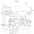
- FIG. 3 is a view showing the first flow state of refrigerant in the outdoor unit shown in FIG. 2 .
- FIG. 3 illustrates the flow state of refrigerant (that is, a first flow state) when the temperature of the refrigerant, which is detected at the outlets of the compressors 110 and 112, exceeds a predetermined temperature, and the pressure of the refrigerant, which is detected at the outlets of the compressors 110 and 112, is lower than a predetermined pressure.
- the refrigerant which is compressed by the compressors 110 and 112 may be supplied to the outdoor heat exchanging unit 140 through the flow diverter 130.
- the refrigerant compressed by the compressors 110 and 112 may be supplied to heat exchangers 141 and 142 provided in the outdoor heat exchanging unit 140.
- the refrigerant (that is, the first refrigerant), which has exchanged heat in the outdoor heat exchanging unit 140, flows into the supercooling heat exchanger 150.
- the first refrigerant which has passed through the supercooling heat exchanger 150, flows toward the indoor unit (not shown), a portion of the first refrigerant (that is, the second refrigerant) is subjected to pressure reduction in the supercooling expansion device 153, provided on the supercooling flow channel 151, and is heated or overheated and evaporated while passing through the supercooling heat exchanger 150.
- the second refrigerant which has flowed out of the supercooling heat exchanger 150, may be guided to or flow into the compressors 110 and 112 through the first guide flow channel 157 and the injection valves 159a and 159b provided on the first guide flow channel 157.
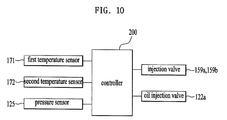
- the bypass valve 156 and the injection valves 159a and 159b may be controlled by a controller 200 (see FIG. 10 ) such that the bypass valve 156 is closed and at least one of the one or more injection valves 159a and 159b is opened.
- the efficiency of the compressors 110 and 112 and the total efficiency of the system may be improved.
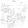
- FIG. 4 is a system chart illustrating the second flow state of refrigerant in the outdoor unit shown in FIG. 2 .
- FIG. 4 illustrates the flow state of refrigerant when the temperature of refrigerant, which is detected at the outlets of the compressors 110 and 112, is lower than the predetermined temperature or the pressure of refrigerant, which is detected at the outlets of the compressors 110 and 112, is equal to or higher than the predetermined pressure.
- the refrigerant which is compressed by the compressors 110 and 112 may be supplied to the outdoor heat exchanging unit 140 through the flow diverter 130. That is, the refrigerant compressed by the compressors 110 and 112 may be supplied to the heat exchangers 141 and 142 provided in the outdoor heat exchanging unit 140.
- the refrigerant (that is, the first refrigerant), which has exchanged heat in the outdoor heat exchanging unit 140, flows into the supercooling heat exchanger 150.
- the first refrigerant which has passed through the supercooling heat exchanger 150, flows toward the indoor unit (not shown), and a portion of the first refrigerant (that is, the second refrigerant) is subjected to pressure reduction in the supercooling expansion device 153, provided on the supercooling flow channel 151, and is heated or overheated and evaporated while passing through the supercooling heat exchanger 150.
- the flow of refrigerant in this case is the same as in the first flow state, which was described with reference to FIG. 3 .
- the second refrigerant which has flowed out of the supercooling heat exchanger 150, may be guided to or flow into the gas-liquid separator 160 through the bypass valve 156 provided on the second guide flow channel 155 and the second guide flow channel 155.
- the gas-phase refrigerant which is separated at the gas-liquid separator 160, may flow into the compressors 110 and 112 through the introduction flow channel 160b.
- the bypass valve 156 and the injection valves 159a and 159b may be controlled by a controller 200 (see FIG. 10 ) such that the bypass valve 156 is opened and the injection valves 159a and 159b are closed.
- the compressors 110 and 112 are protected from damage and the efficiency of the compressors 110 and 112 and the overall system may be improved.
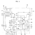
- FIG. 5 is a system chart illustrating the outdoor unit shown in FIG. 2 to which an oil injection line is additionally applied.
- the first recovery flow channel 116 which connects the first oil separator 120 to the first compressor 110 so as to transfer the oil separated by the first oil separator 120, may be provided with the oil injection line 122b for transferring the oil to the first injection flow channel 158a.
- FIG. 5 shows an example in which the oil injection line 122b is provided only on the first recovery flow channel 116, which communicates with the first compressor 110, the oil injection line may also be provided on the second recovery flow channel 116a that communicates with the second compressor 112.
- the oil injection line 122b may be branched from the first recovery flow channel 116 and may communicate with the first injection flow channel 158a, which serves to allow gas-phase refrigerant to flow into the first compressor 110, such that oil separated by the first oil separator 120 flows into the first compressor 110 through the first injection flow channel 158a and a second input end 340, which will be described later, rather than flowing into the first compressor 110 through the first recovery flow channel 116.
- the first injection flow channel 158a serves as a flow channel through which gas-phase refrigerant flows into the first compressor 110 in the heating operation as described above, it is impossible to cause the oil, separated by the first oil separator 120, to flow into the first compressor 110 through the first injection flow channel 158a and the second input end 340 in the heating operation.
- the first injection flow channel 158a is preferably used as a flow channel through which gas-phase refrigerant flows into the first compressor 110 in the heating operation, and the first injection flow channel 158a is preferably used as a flow channel through which the oil separated by the first oil separator 120 flows into the first compressor 110 in the cooling operation.
- the present invention is not limited thereto. That is, the oil may directly flow into the first compressor 110 through the second input end 340 without passing through the first injection flow channel 158a.
- the oil injection line 122b may further include an oil injection valve 122a for checking the flow of oil through the oil injection line 122b.
- the oil injection valve 122a is closed so as to prevent oil from flowing through the oil injection line 122b in the heating operation, and is opened so as to allow oil to flow through the oil injection line 122b in the cooling operation.
- FIGs. 6 and 7 show the compressor according to the present invention.
- the compressor according to the present invention may include a compressor housing 390 defining the appearance of the compressor, a motor 370, which is disposed in the compressor housing 390 so as to generate rotational force, a shaft 360, which is connected at one end thereof to the motor 370 and at the other end thereof to an orbiting scroll 310 so as to transmit the rotational force of the motor 370 to the orbiting scroll 310, and a fixed scroll 300, which is secured in the state of being spaced apart from the orbiting scroll 310 by a predetermined distance.
- the upper part of the compressor may include a first input end 330, at which high pressure is created, a third input end 350, at which low pressure is created, and the second input end 340, at which intermediate pressure (hereinafter, referred to as "an intermediate pressure"), which is between the high pressure at the first input end 330 and the low pressure at the third input end 350, is created.
- an intermediate pressure intermediate pressure
- FIG. 7 is a plan view showing the upper surface of the compressor.
- the orbiting scroll 310 may engage with the fixed scroll 300 such that the orbiting scroll 310 rotates in the state of being spaced apart from the fixed scroll 300 by a predetermined distance.
- Compressed gas G is positioned between the fixed scroll 300 and the orbiting scroll 310. As the orbiting scroll 310 rotates, the gap between the fixed scroll 300 and the orbiting scroll 310 is reduced, and the compressed gas G is compressed under high pressure.
- the compressed gas G which is compressed under the high pressure, is discharged to the outside of the compressor through a discharge hole 320.
- FIG. 8 is a cross-sectional view showing the scrolls of the compressor in a medium or high-speed operation.
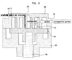
- FIG. 9 is a cross-sectional view showing the scrolls of the compressor in a low-speed operation.
- FIG. 10 is a block diagram showing the controller of the air conditioner according to the present invention.
- the shaft 360 which serves to transmit the rotational force of the motor 370 to the orbiting scroll 310 as described above, is disposed in a scroll housing 380, and the orbiting scroll 310 is rotatably mounted on the upper part of the scroll housing 380.
- the fixed scroll 300 may engage with the orbiting scroll 310 in the state of being spaced apart from the orbiting scroll 310 by a predetermined distance.
- the compressed gas G is positioned between the orbiting scroll 310 and the fixed scroll 300. As shown in the drawing, the compressed gas G generates gas force GF toward the center of the circular motion of the orbiting scroll 310.
- the orbiting scroll 310 Since the orbiting scroll 310 is rotated by the shaft 360, the orbiting scroll 310 generates centrifugal force CF in an outward direction from the center of the circular motion.
- the centrifugal force CF generated by the orbiting scroll 310 may be lower than the centrifugal force CF during medium or high-speed operation.
- a gap may be formed between the orbiting scroll 310 and the fixed scroll 300, but is not formed during medium or high-speed operation because the gas force GF is balanced with the centrifugal force CF.
- the occurrence of the gap between the orbiting scroll 310 and the fixed scroll 300 causes a problem in that the amount of refrigerant leaking through the gap is increased, thus decreasing the overall efficiency of the compressor.
- the compressor according to the present invention may include an oil injection hole 345 through which oil O flows into the second input end 340.
- the oil separated by the first oil separator 120 may enter into the oil injection hole 345 through the oil injection line 122b, which communicates with the first recovery flow channel 116.
- the oil O which is introduced into the oil injection hole 345, flows between the fixed scroll 300 and the orbiting scroll 310, and fills the gap that is formed between the fixed scroll 300 and the orbiting scroll 310 during a low-speed operation, thereby preventing refrigerant from leaking through the gap and thus increasing the efficiency of the compressor.
- the oil injection valve 122a which is provided on the oil injection line 122b so as to open and close the oil injection line 122b, is controlled to be opened so as to allow the oil O to flow into the compressor only during the cooling operation at which the compressor is operated at a low speed.
- FIG. 11 is a flowchart showing the process of controlling the air conditioner according to the present invention.
- the process of controlling the air conditioner may include a cooling operation determination operation (S100) of determining whether the air conditioner is to be used to executed a cooling operation based on user input or the like, an oil injection valve opening operation (S200) of opening the oil injection valve 122a if it is determined in the cooling operation determination operation (S100) that the cooling operation is to be executed, and an injection valve closing operation (S300) of closing the injection valve after the oil injection valve 122a is opened.
- a cooling operation determination operation S100
- S200 oil injection valve opening operation
- S300 injection valve closing operation
- the process may further include an oil injection valve closing operation (S210) of closing the oil injection valve 122a and an injection valve opening operation (S310) of opening the injection valve after the oil injection valve 122a is closed.
- the present invention provides an air conditioner in which the compression efficiency of the compressor is not decreased even during the cooling operation.
- the present invention provides an air conditioner in which the compression efficiency of the compressor is not decreased when the compressor is operated at a low speed.
Landscapes
- Engineering & Computer Science (AREA)
- Mechanical Engineering (AREA)
- General Engineering & Computer Science (AREA)
- Physics & Mathematics (AREA)
- Thermal Sciences (AREA)
- Chemical & Material Sciences (AREA)
- Analytical Chemistry (AREA)
- Power Engineering (AREA)
- Combustion & Propulsion (AREA)
- Compression-Type Refrigeration Machines With Reversible Cycles (AREA)
- Air Conditioning Control Device (AREA)
- Applications Or Details Of Rotary Compressors (AREA)
Applications Claiming Priority (1)
| Application Number | Priority Date | Filing Date | Title |
|---|---|---|---|
| KR1020150018773A KR102264023B1 (ko) | 2015-02-06 | 2015-02-06 | 공기조화기 |
Publications (2)
| Publication Number | Publication Date |
|---|---|
| EP3054237A1 true EP3054237A1 (fr) | 2016-08-10 |
| EP3054237B1 EP3054237B1 (fr) | 2021-07-21 |
Family
ID=55262723
Family Applications (1)
| Application Number | Title | Priority Date | Filing Date |
|---|---|---|---|
| EP16152910.2A Active EP3054237B1 (fr) | 2015-02-06 | 2016-01-27 | Climatiseur |
Country Status (4)
| Country | Link |
|---|---|
| US (1) | US10145593B2 (fr) |
| EP (1) | EP3054237B1 (fr) |
| KR (1) | KR102264023B1 (fr) |
| CN (1) | CN105865072B (fr) |
Cited By (1)
| Publication number | Priority date | Publication date | Assignee | Title |
|---|---|---|---|---|
| CN108061102A (zh) * | 2016-11-09 | 2018-05-22 | 斯凯孚公司 | 冷却系统 |
Families Citing this family (7)
| Publication number | Priority date | Publication date | Assignee | Title |
|---|---|---|---|---|
| JP6786965B2 (ja) * | 2016-09-01 | 2020-11-18 | ダイキン工業株式会社 | 冷凍装置 |
| CN107575939B (zh) * | 2017-09-07 | 2019-10-25 | 珠海格力电器股份有限公司 | 多联机系统及其控制方法 |
| WO2019129113A1 (fr) * | 2017-12-28 | 2019-07-04 | 艾默生环境优化技术(苏州)有限公司 | Tuyau d'admission d'air utilisé pour un système de compresseur et système de compresseur |
| US11585608B2 (en) | 2018-02-05 | 2023-02-21 | Emerson Climate Technologies, Inc. | Climate-control system having thermal storage tank |
| US11149971B2 (en) | 2018-02-23 | 2021-10-19 | Emerson Climate Technologies, Inc. | Climate-control system with thermal storage device |
| CN112236629B (zh) | 2018-05-15 | 2022-03-01 | 艾默生环境优化技术有限公司 | 具有接地环路的气温控制系统及方法 |
| US11346583B2 (en) * | 2018-06-27 | 2022-05-31 | Emerson Climate Technologies, Inc. | Climate-control system having vapor-injection compressors |
Citations (3)
| Publication number | Priority date | Publication date | Assignee | Title |
|---|---|---|---|---|
| JP2010032205A (ja) * | 2008-07-02 | 2010-02-12 | Daikin Ind Ltd | 冷凍装置 |
| EP2320159A1 (fr) * | 2008-07-31 | 2011-05-11 | Daikin Industries, Ltd. | Dispositif de réfrigération |
| EP2966381A1 (fr) * | 2014-07-07 | 2016-01-13 | LG Electronics Inc. | Climatiseur |
Family Cites Families (4)
| Publication number | Priority date | Publication date | Assignee | Title |
|---|---|---|---|---|
| JP4193475B2 (ja) * | 2002-11-22 | 2008-12-10 | ダイキン工業株式会社 | 圧縮機構の均油回路、空気調和装置の熱源ユニット及びそれを備えた空気調和装置 |
| JP4665560B2 (ja) * | 2005-03-04 | 2011-04-06 | ダイキン工業株式会社 | 冷凍装置 |
| JP4807071B2 (ja) * | 2005-12-27 | 2011-11-02 | ダイキン工業株式会社 | 冷凍装置 |
| KR101382007B1 (ko) * | 2012-08-01 | 2014-04-04 | 엘지전자 주식회사 | 스크롤 압축기 및 이를 포함하는 공기 조화기 |
-
2015
- 2015-02-06 KR KR1020150018773A patent/KR102264023B1/ko not_active Expired - Fee Related
-
2016
- 2016-01-08 CN CN201610009544.3A patent/CN105865072B/zh active Active
- 2016-01-27 EP EP16152910.2A patent/EP3054237B1/fr active Active
- 2016-02-02 US US15/012,927 patent/US10145593B2/en active Active
Patent Citations (3)
| Publication number | Priority date | Publication date | Assignee | Title |
|---|---|---|---|---|
| JP2010032205A (ja) * | 2008-07-02 | 2010-02-12 | Daikin Ind Ltd | 冷凍装置 |
| EP2320159A1 (fr) * | 2008-07-31 | 2011-05-11 | Daikin Industries, Ltd. | Dispositif de réfrigération |
| EP2966381A1 (fr) * | 2014-07-07 | 2016-01-13 | LG Electronics Inc. | Climatiseur |
Cited By (1)
| Publication number | Priority date | Publication date | Assignee | Title |
|---|---|---|---|---|
| CN108061102A (zh) * | 2016-11-09 | 2018-05-22 | 斯凯孚公司 | 冷却系统 |
Also Published As
| Publication number | Publication date |
|---|---|
| CN105865072B (zh) | 2018-05-29 |
| US10145593B2 (en) | 2018-12-04 |
| EP3054237B1 (fr) | 2021-07-21 |
| US20160231035A1 (en) | 2016-08-11 |
| KR20160097000A (ko) | 2016-08-17 |
| CN105865072A (zh) | 2016-08-17 |
| KR102264023B1 (ko) | 2021-06-11 |
Similar Documents
| Publication | Publication Date | Title |
|---|---|---|
| EP3054237B1 (fr) | Climatiseur | |
| EP2083230B1 (fr) | Système de climatisation | |
| US12352477B2 (en) | Refrigeration apparatus-use unit, heat source unit, and refrigeration apparatus | |
| US7204094B2 (en) | Air conditioner | |
| EP2479519B1 (fr) | Système réfrigérant | |
| US20110174005A1 (en) | Refrigerating apparatus | |
| EP3034962B1 (fr) | Climatiseur | |
| US20170108250A1 (en) | Air conditioner | |
| US11598559B2 (en) | Heat source-side unit and refrigeration apparatus | |
| US20040182101A1 (en) | Heat pump apparatus | |
| JP2013181736A (ja) | コンテナ用冷凍装置 | |
| EP2966381B1 (fr) | Climatiseur | |
| EP3043125B1 (fr) | Climatiseur | |
| JP5765325B2 (ja) | 冷凍装置 | |
| JP6758485B2 (ja) | 冷凍サイクル装置 | |
| EP2354728B1 (fr) | Système réfrigérant | |
| KR20210073990A (ko) | 히트펌프시스템 | |
| CN114341571B (zh) | 制冷装置 | |
| JP5659909B2 (ja) | ヒートポンプ装置 | |
| WO2021059635A1 (fr) | Dispositif frigorifique | |
| KR20080089962A (ko) | 공기조화기 | |
| KR20140093449A (ko) | 공기 조화기 및 그 제어방법 | |
| JP2002147878A (ja) | ヒートポンプ装置 | |
| KR100364535B1 (ko) | 냉난방 겸용 멀티형 공기조화기 | |
| KR20160073162A (ko) | 공기조화기 및 그 제어방법 |
Legal Events
| Date | Code | Title | Description |
|---|---|---|---|
| PUAI | Public reference made under article 153(3) epc to a published international application that has entered the european phase |
Free format text: ORIGINAL CODE: 0009012 |
|
| 17P | Request for examination filed |
Effective date: 20160226 |
|
| AK | Designated contracting states |
Kind code of ref document: A1 Designated state(s): AL AT BE BG CH CY CZ DE DK EE ES FI FR GB GR HR HU IE IS IT LI LT LU LV MC MK MT NL NO PL PT RO RS SE SI SK SM TR |
|
| AX | Request for extension of the european patent |
Extension state: BA ME |
|
| RBV | Designated contracting states (corrected) |
Designated state(s): AL AT BE BG CH CY CZ DE DK EE ES FI FR GB GR HR HU IE IS IT LI LT LU LV MC MK MT NL NO PL PT RO RS SE SI SK SM TR |
|
| STAA | Information on the status of an ep patent application or granted ep patent |
Free format text: STATUS: EXAMINATION IS IN PROGRESS |
|
| 17Q | First examination report despatched |
Effective date: 20200330 |
|
| GRAP | Despatch of communication of intention to grant a patent |
Free format text: ORIGINAL CODE: EPIDOSNIGR1 |
|
| STAA | Information on the status of an ep patent application or granted ep patent |
Free format text: STATUS: GRANT OF PATENT IS INTENDED |
|
| RIC1 | Information provided on ipc code assigned before grant |
Ipc: F25B 49/02 20060101ALI20210118BHEP Ipc: F25B 31/00 20060101ALI20210118BHEP Ipc: F25B 1/04 20060101AFI20210118BHEP Ipc: F25B 13/00 20060101ALN20210118BHEP |
|
| INTG | Intention to grant announced |
Effective date: 20210204 |
|
| GRAS | Grant fee paid |
Free format text: ORIGINAL CODE: EPIDOSNIGR3 |
|
| GRAA | (expected) grant |
Free format text: ORIGINAL CODE: 0009210 |
|
| STAA | Information on the status of an ep patent application or granted ep patent |
Free format text: STATUS: THE PATENT HAS BEEN GRANTED |
|
| AK | Designated contracting states |
Kind code of ref document: B1 Designated state(s): AL AT BE BG CH CY CZ DE DK EE ES FI FR GB GR HR HU IE IS IT LI LT LU LV MC MK MT NL NO PL PT RO RS SE SI SK SM TR |
|
| REG | Reference to a national code |
Ref country code: GB Ref legal event code: FG4D |
|
| REG | Reference to a national code |
Ref country code: CH Ref legal event code: EP |
|
| REG | Reference to a national code |
Ref country code: DE Ref legal event code: R096 Ref document number: 602016060819 Country of ref document: DE |
|
| REG | Reference to a national code |
Ref country code: AT Ref legal event code: REF Ref document number: 1412942 Country of ref document: AT Kind code of ref document: T Effective date: 20210815 |
|
| REG | Reference to a national code |
Ref country code: IE Ref legal event code: FG4D |
|
| REG | Reference to a national code |
Ref country code: LT Ref legal event code: MG9D |
|
| REG | Reference to a national code |
Ref country code: NL Ref legal event code: MP Effective date: 20210721 |
|
| REG | Reference to a national code |
Ref country code: AT Ref legal event code: MK05 Ref document number: 1412942 Country of ref document: AT Kind code of ref document: T Effective date: 20210721 |
|
| PG25 | Lapsed in a contracting state [announced via postgrant information from national office to epo] |
Ref country code: SE Free format text: LAPSE BECAUSE OF FAILURE TO SUBMIT A TRANSLATION OF THE DESCRIPTION OR TO PAY THE FEE WITHIN THE PRESCRIBED TIME-LIMIT Effective date: 20210721 Ref country code: RS Free format text: LAPSE BECAUSE OF FAILURE TO SUBMIT A TRANSLATION OF THE DESCRIPTION OR TO PAY THE FEE WITHIN THE PRESCRIBED TIME-LIMIT Effective date: 20210721 Ref country code: HR Free format text: LAPSE BECAUSE OF FAILURE TO SUBMIT A TRANSLATION OF THE DESCRIPTION OR TO PAY THE FEE WITHIN THE PRESCRIBED TIME-LIMIT Effective date: 20210721 Ref country code: NO Free format text: LAPSE BECAUSE OF FAILURE TO SUBMIT A TRANSLATION OF THE DESCRIPTION OR TO PAY THE FEE WITHIN THE PRESCRIBED TIME-LIMIT Effective date: 20211021 Ref country code: PT Free format text: LAPSE BECAUSE OF FAILURE TO SUBMIT A TRANSLATION OF THE DESCRIPTION OR TO PAY THE FEE WITHIN THE PRESCRIBED TIME-LIMIT Effective date: 20211122 Ref country code: NL Free format text: LAPSE BECAUSE OF FAILURE TO SUBMIT A TRANSLATION OF THE DESCRIPTION OR TO PAY THE FEE WITHIN THE PRESCRIBED TIME-LIMIT Effective date: 20210721 Ref country code: FI Free format text: LAPSE BECAUSE OF FAILURE TO SUBMIT A TRANSLATION OF THE DESCRIPTION OR TO PAY THE FEE WITHIN THE PRESCRIBED TIME-LIMIT Effective date: 20210721 Ref country code: ES Free format text: LAPSE BECAUSE OF FAILURE TO SUBMIT A TRANSLATION OF THE DESCRIPTION OR TO PAY THE FEE WITHIN THE PRESCRIBED TIME-LIMIT Effective date: 20210721 Ref country code: LT Free format text: LAPSE BECAUSE OF FAILURE TO SUBMIT A TRANSLATION OF THE DESCRIPTION OR TO PAY THE FEE WITHIN THE PRESCRIBED TIME-LIMIT Effective date: 20210721 Ref country code: BG Free format text: LAPSE BECAUSE OF FAILURE TO SUBMIT A TRANSLATION OF THE DESCRIPTION OR TO PAY THE FEE WITHIN THE PRESCRIBED TIME-LIMIT Effective date: 20211021 Ref country code: AT Free format text: LAPSE BECAUSE OF FAILURE TO SUBMIT A TRANSLATION OF THE DESCRIPTION OR TO PAY THE FEE WITHIN THE PRESCRIBED TIME-LIMIT Effective date: 20210721 |
|
| PG25 | Lapsed in a contracting state [announced via postgrant information from national office to epo] |
Ref country code: PL Free format text: LAPSE BECAUSE OF FAILURE TO SUBMIT A TRANSLATION OF THE DESCRIPTION OR TO PAY THE FEE WITHIN THE PRESCRIBED TIME-LIMIT Effective date: 20210721 Ref country code: LV Free format text: LAPSE BECAUSE OF FAILURE TO SUBMIT A TRANSLATION OF THE DESCRIPTION OR TO PAY THE FEE WITHIN THE PRESCRIBED TIME-LIMIT Effective date: 20210721 Ref country code: GR Free format text: LAPSE BECAUSE OF FAILURE TO SUBMIT A TRANSLATION OF THE DESCRIPTION OR TO PAY THE FEE WITHIN THE PRESCRIBED TIME-LIMIT Effective date: 20211022 |
|
| REG | Reference to a national code |
Ref country code: DE Ref legal event code: R097 Ref document number: 602016060819 Country of ref document: DE |
|
| PG25 | Lapsed in a contracting state [announced via postgrant information from national office to epo] |
Ref country code: DK Free format text: LAPSE BECAUSE OF FAILURE TO SUBMIT A TRANSLATION OF THE DESCRIPTION OR TO PAY THE FEE WITHIN THE PRESCRIBED TIME-LIMIT Effective date: 20210721 |
|
| PLBE | No opposition filed within time limit |
Free format text: ORIGINAL CODE: 0009261 |
|
| STAA | Information on the status of an ep patent application or granted ep patent |
Free format text: STATUS: NO OPPOSITION FILED WITHIN TIME LIMIT |
|
| PG25 | Lapsed in a contracting state [announced via postgrant information from national office to epo] |
Ref country code: SM Free format text: LAPSE BECAUSE OF FAILURE TO SUBMIT A TRANSLATION OF THE DESCRIPTION OR TO PAY THE FEE WITHIN THE PRESCRIBED TIME-LIMIT Effective date: 20210721 Ref country code: SK Free format text: LAPSE BECAUSE OF FAILURE TO SUBMIT A TRANSLATION OF THE DESCRIPTION OR TO PAY THE FEE WITHIN THE PRESCRIBED TIME-LIMIT Effective date: 20210721 Ref country code: RO Free format text: LAPSE BECAUSE OF FAILURE TO SUBMIT A TRANSLATION OF THE DESCRIPTION OR TO PAY THE FEE WITHIN THE PRESCRIBED TIME-LIMIT Effective date: 20210721 Ref country code: EE Free format text: LAPSE BECAUSE OF FAILURE TO SUBMIT A TRANSLATION OF THE DESCRIPTION OR TO PAY THE FEE WITHIN THE PRESCRIBED TIME-LIMIT Effective date: 20210721 Ref country code: CZ Free format text: LAPSE BECAUSE OF FAILURE TO SUBMIT A TRANSLATION OF THE DESCRIPTION OR TO PAY THE FEE WITHIN THE PRESCRIBED TIME-LIMIT Effective date: 20210721 Ref country code: AL Free format text: LAPSE BECAUSE OF FAILURE TO SUBMIT A TRANSLATION OF THE DESCRIPTION OR TO PAY THE FEE WITHIN THE PRESCRIBED TIME-LIMIT Effective date: 20210721 |
|
| 26N | No opposition filed |
Effective date: 20220422 |
|
| PG25 | Lapsed in a contracting state [announced via postgrant information from national office to epo] |
Ref country code: MC Free format text: LAPSE BECAUSE OF FAILURE TO SUBMIT A TRANSLATION OF THE DESCRIPTION OR TO PAY THE FEE WITHIN THE PRESCRIBED TIME-LIMIT Effective date: 20210721 |
|
| REG | Reference to a national code |
Ref country code: CH Ref legal event code: PL |
|
| GBPC | Gb: european patent ceased through non-payment of renewal fee |
Effective date: 20220127 |
|
| REG | Reference to a national code |
Ref country code: BE Ref legal event code: MM Effective date: 20220131 |
|
| PG25 | Lapsed in a contracting state [announced via postgrant information from national office to epo] |
Ref country code: LU Free format text: LAPSE BECAUSE OF NON-PAYMENT OF DUE FEES Effective date: 20220127 Ref country code: GB Free format text: LAPSE BECAUSE OF NON-PAYMENT OF DUE FEES Effective date: 20220127 |
|
| PG25 | Lapsed in a contracting state [announced via postgrant information from national office to epo] |
Ref country code: FR Free format text: LAPSE BECAUSE OF NON-PAYMENT OF DUE FEES Effective date: 20220131 Ref country code: BE Free format text: LAPSE BECAUSE OF NON-PAYMENT OF DUE FEES Effective date: 20220131 |
|
| PG25 | Lapsed in a contracting state [announced via postgrant information from national office to epo] |
Ref country code: LI Free format text: LAPSE BECAUSE OF NON-PAYMENT OF DUE FEES Effective date: 20220131 Ref country code: CH Free format text: LAPSE BECAUSE OF NON-PAYMENT OF DUE FEES Effective date: 20220131 |
|
| PG25 | Lapsed in a contracting state [announced via postgrant information from national office to epo] |
Ref country code: IE Free format text: LAPSE BECAUSE OF NON-PAYMENT OF DUE FEES Effective date: 20220127 |
|
| PG25 | Lapsed in a contracting state [announced via postgrant information from national office to epo] |
Ref country code: HU Free format text: LAPSE BECAUSE OF FAILURE TO SUBMIT A TRANSLATION OF THE DESCRIPTION OR TO PAY THE FEE WITHIN THE PRESCRIBED TIME-LIMIT; INVALID AB INITIO Effective date: 20160127 |
|
| PG25 | Lapsed in a contracting state [announced via postgrant information from national office to epo] |
Ref country code: MK Free format text: LAPSE BECAUSE OF FAILURE TO SUBMIT A TRANSLATION OF THE DESCRIPTION OR TO PAY THE FEE WITHIN THE PRESCRIBED TIME-LIMIT Effective date: 20210721 Ref country code: CY Free format text: LAPSE BECAUSE OF FAILURE TO SUBMIT A TRANSLATION OF THE DESCRIPTION OR TO PAY THE FEE WITHIN THE PRESCRIBED TIME-LIMIT Effective date: 20210721 |
|
| PG25 | Lapsed in a contracting state [announced via postgrant information from national office to epo] |
Ref country code: TR Free format text: LAPSE BECAUSE OF FAILURE TO SUBMIT A TRANSLATION OF THE DESCRIPTION OR TO PAY THE FEE WITHIN THE PRESCRIBED TIME-LIMIT Effective date: 20210721 |
|
| PG25 | Lapsed in a contracting state [announced via postgrant information from national office to epo] |
Ref country code: MT Free format text: LAPSE BECAUSE OF FAILURE TO SUBMIT A TRANSLATION OF THE DESCRIPTION OR TO PAY THE FEE WITHIN THE PRESCRIBED TIME-LIMIT Effective date: 20210721 |
|
| PGFP | Annual fee paid to national office [announced via postgrant information from national office to epo] |
Ref country code: DE Payment date: 20251208 Year of fee payment: 11 |
|
| PGFP | Annual fee paid to national office [announced via postgrant information from national office to epo] |
Ref country code: IT Payment date: 20251209 Year of fee payment: 11 |