EP3054253A1 - Article d'échangeur de chaleur à tube creux ayant une pluralité d'aubes - Google Patents
Article d'échangeur de chaleur à tube creux ayant une pluralité d'aubes Download PDFInfo
- Publication number
- EP3054253A1 EP3054253A1 EP16154908.4A EP16154908A EP3054253A1 EP 3054253 A1 EP3054253 A1 EP 3054253A1 EP 16154908 A EP16154908 A EP 16154908A EP 3054253 A1 EP3054253 A1 EP 3054253A1
- Authority
- EP
- European Patent Office
- Prior art keywords
- vane
- heat exchanger
- vanes
- recited
- twist
- Prior art date
- Legal status (The legal status is an assumption and is not a legal conclusion. Google has not performed a legal analysis and makes no representation as to the accuracy of the status listed.)
- Granted
Links
Images

Classifications
-
- F—MECHANICAL ENGINEERING; LIGHTING; HEATING; WEAPONS; BLASTING
- F28—HEAT EXCHANGE IN GENERAL
- F28F—DETAILS OF HEAT-EXCHANGE AND HEAT-TRANSFER APPARATUS, OF GENERAL APPLICATION
- F28F1/00—Tubular elements; Assemblies of tubular elements
- F28F1/10—Tubular elements and assemblies thereof with means for increasing heat-transfer area, e.g. with fins, with projections, with recesses
- F28F1/40—Tubular elements and assemblies thereof with means for increasing heat-transfer area, e.g. with fins, with projections, with recesses the means being only inside the tubular element
-
- F—MECHANICAL ENGINEERING; LIGHTING; HEATING; WEAPONS; BLASTING
- F28—HEAT EXCHANGE IN GENERAL
- F28F—DETAILS OF HEAT-EXCHANGE AND HEAT-TRANSFER APPARATUS, OF GENERAL APPLICATION
- F28F1/00—Tubular elements; Assemblies of tubular elements
- F28F1/10—Tubular elements and assemblies thereof with means for increasing heat-transfer area, e.g. with fins, with projections, with recesses
- F28F1/42—Tubular elements and assemblies thereof with means for increasing heat-transfer area, e.g. with fins, with projections, with recesses the means being both outside and inside the tubular element
- F28F1/422—Tubular elements and assemblies thereof with means for increasing heat-transfer area, e.g. with fins, with projections, with recesses the means being both outside and inside the tubular element with outside means integral with the tubular element and inside means integral with the tubular element
Definitions
- This disclosure relates to heat exchangers and, more particularly, to heat exchanger tubes that have internal features for enhancing thermal exchange.
- a heat exchanger can include one or more tubes for transferring a first working fluid.
- a second working fluid can be passed around the outside of the tubes such that there is a thermal exchange between the two working fluids.
- the tube can include pins on the inside that are used to increase surface area and thus increase heat transfer between the fluids.
- the tubes and pins are typically fabricated by joining several pieces together using welding or brazing techniques.
- a heat exchanger article includes a hollow tube including a tube wall with an interior surface and an exterior surface, the interior surface defines a flow passage through the hollow tube, and a vane cluster in the flow passage.
- the vane cluster includes a plurality of vanes, and each of the vanes extends inwardly from the tube wall.
- the vanes of the vane cluster extend inwardly toward a common central axis of the hollow tube.
- each of the vanes has a twist from a vane leading edge to a vane trailing edge.
- each of the vanes has an airfoil shape.
- vanes of the vane cluster meet at a central hub.
- the hollow tube includes a plurality of protrusions extending outwardly from the exterior surface.
- each of the vanes has a length from a vane leading edge to a vane trailing edge and a span from a vane outer side to a vane inner side, and a ratio of the length to the span is greater than 1:1.
- the hollow tube is monolithic.
- a heat exchanger article includes a hollow tube including a tube wall with an interior surface and an exterior surface, the interior surface defines a flow passage through the hollow tube, and a series of vane clusters spaced apart in the flow passage.
- Each of the vane clusters includes a plurality of vanes, and each of the vanes extends inwardly from the tube wall.
- At least one of the vane clusters has a clockwise twist and at least one other of the vane clusters has a counter-clockwise twist.
- the series of vane clusters has an alternating arrangement of vane clusters with regard to clockwise twist and counter-clockwise twist.
- each of the vane clusters has a twist
- the series of vane clusters has a progressively changing twist
- each of the vane clusters has a twist
- the series of vane clusters has a progressively changing twist between clockwise twist and counter-clockwise twist.
- the flow passage is unobstructed between the vane clusters.
- the hollow tube is monolithic.
- a heat exchanger article includes a hollow monolithic tube that has first and second ends.
- the monolithic tube includes a tube wall that circumscribes a flow passage that extends from the first end to the second end, and a plurality of vanes that are spaced from at least one of the first and second ends and that extend inwardly from the tube wall.
- each of the vanes extends inwardly toward a common central axis of the monolithic tube.
- each of the vanes has a twist from a vane leading edge to a vane trailing edge.
- each of the vanes has an airfoil shape.
- FIG. 1 schematically illustrates an example heat exchanger 20 that has one or more heat exchanger articles 22.
- the heat exchanger article 22 is a hollow tube 24.
- the hollow tube 24 is formed of an alloy material, such as but not limited to aluminum alloy, nickel alloy, iron alloy, or copper alloy.
- a working fluid is passed through the hollow tube 24 and a second working fluid is passed around the outside of the hollow tube 24 such that there is a thermal exchange between the two working fluids.
- this disclosure is not limited to any particular type of heat exchanger, and the examples herein can be applied to other types of heat exchangers.
- Some heat exchanger tubes include internal pins that function to increase surface area for greater thermal exchange.
- manufacturing processes such as brazing and welding limit the type and geometry of internal features.
- an alternative fabrication process such as additive manufacturing, can be used to fabricate internal features that are not feasible using other manufacturing techniques.
- the hollow tube 24 includes a tube wall 26 that has an interior surface 26a and an exterior surface 26b.
- the interior surface 26a defines a flow passage 28 through the hollow tube 24.
- the hollow tube 24 also includes a static vane cluster 30 in the flow passage 28.
- the vane cluster 30 includes a plurality of vanes 32, and each of the vanes 32 extends inwardly from the tube wall 26. For instance, the vanes 32 extend from the tube wall 26, rather than an intermediate structure.
- Each of the vanes 32 includes a leading edge 34 and a trailing edge 36 that define a length dimension that is generally parallel to a central axis A of the hollow tube 24.
- the vanes 32 each also have a span dimension from a vane outer side 38 at the tube wall 26 to a vane inner side 40 that is spaced inwardly from the tube wall 26.
- the vanes 32 are longer than they are wide, and the vanes thus have a ratio of length to span that is greater than 1:1.
- each of the vanes 32 also has a vane twist. That is, the body of each of the vanes 32 twists along the length direction.
- the twist of the vanes 32 serves to swirl working fluid that flows through the flow passage 28 over the vanes 32.
- the vanes 32 can have either a clockwise twist or a counterclockwise twist to cause, respectively, clockwise or counterclockwise swirl of the fluid.
- the swirl of the working fluid serves to promote a more uniform temperature distribution.
- the vanes 32 increase surface area and, therefore, also promote heat transfer through the tube wall 26.
- each of the vanes 32 extends radially inwardly toward the common central axis A of the hollow tube 24.
- the vanes 32 meet at a hub 42, which joins all of the vanes 32 and structurally supports the vanes 32 relative to the tube wall 26.
- the hub 42 is cylindrical, although the hub 42 could alternatively have a different geometry.
- the hub 42 is excluded such that the vanes 32 either have free inner ides or the vanes 32 meet at a relatively smaller hub.
- Additive manufacturing can be used to form the tube wall 26 and the vane cluster 30.
- Additive manufacturing involves building an article layer-by-layer from a powder material by consolidating selected portions of each successive layer of powder until the complete article is formed. For example, the powder is fed into a chamber, which may be under vacuum or inert cover gas. A machine deposits multiple layers of the powder onto one another. An energy beam, such as a laser, selectively heats and consolidates each layer with reference to a computer-aided design data to form solid structures that relate to a particular cross-section of the article. Other layers or portions of layers corresponding to negative features, such as cavities or openings, are not joined and thus remain as a powdered material. The unjoined powder material may later be removed using blown air, for example.
- the article With the layers built upon one another and joined to one another cross-section by cross-section, the article, or a portion thereof, such as for a repair, is produced.
- the article may be post-processed to provide desired structural characteristics.
- the article may be heat treated to produce a desired microstructure.
- Additive manufacturing processes can include, but are not limited to, selective laser melting, direct metal laser sintering, electron beam melting, 3D printing, laser engineered net shaping, or laser powder forming.
- the additive manufacturing process can be used to form the hollow tube 24 as a monolithic tube.
- the hollow tube 24 is seamless with regard to distinct boundaries that would otherwise be formed using techniques such as welding or brazing.
- the (monolithic) hollow tube 24, in one example is free of seams such that there are no distinct boundaries or discontinuities in the hollow tube 24 that are visually or microscopically discernable.
- Figure 2 illustrates a further example of a representative vane 132 that can be used in the hollow tube 24.
- the vane 132 has an airfoil shape 150.
- An airfoil shape is a geometry that provides a reaction force as fluid flows over the airfoil.
- the vanes 132 are static in the hollow tube 24, the airfoil shape can facilitate the reduction of friction.
- Figure 3 illustrates another example hollow tube 124.
- like reference numerals designate like elements where appropriate and reference numerals with the addition of one-hundred are multiples thereof designate modified elements that are understood to incorporate the same features and benefits of the corresponding elements.
- the hollow tube 124 includes a series 144 of the vane clusters 30 spaced apart in the flow passage 28.
- Each of the vane clusters 30 can have either a clockwise twist or a counterclockwise twist.
- all of the vane clusters 30 have a counterclockwise twist relative to the direction of flow through the flow passage 28 (from left to right in the figure).
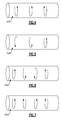
- Figures 4-7 illustrate further example configurations with regard to the twist of the vane clusters 30.
- the twist of the vane clusters is represented by illustrated clocking arrows.
- Each clocking arrow represents a direction of twist, either clockwise or counterclockwise, and a degree of twist that corresponds to the length of the arrow.
- the hollow tube 24 includes two vane clusters that have a counterclockwise twist and another vane cluster that has a clockwise twist.
- the hollow tube 324 has a progressively changing twist.
- the first vane cluster has a relatively low degree of twist
- the second vane cluster has a greater amount of twist than the first vane cluster
- the last vane cluster on the right-hand side has a third, greatest amount of twist.
- the hollow tube 424 in Figure 6 has a twist that progressively changes between counterclockwise and clockwise.
- the first vane cluster has a counterclockwise twist
- the second vane cluster has a lesser degree of counterclockwise twist
- the third vane cluster has a clockwise twist
- the fourth vane cluster has a greater degree of clockwise twist.
- the swirl of the fluid traveling down the hollow tube 24 is gradually changed from counterclockwise to clockwise.
- the swirl could also go from clockwise to counterclockwise, and there could also be alternating segments of changing between clockwise, counterclockwise, and then back to clockwise.
- the hollow tube 524 in Figure 7 has an alternating arrangement of vane clusters with regard to clockwise twist and counterclockwise twist.
- the first vane cluster has a counterclockwise twist
- the second vane cluster a clockwise twist
- the third vane cluster a counterclockwise twist
- the last vane cluster a clockwise twist.
- the segments shown in the above example are representative, and in further examples, these segments can be repeated or combined with one another to facilitate swirling of the fluid and uniform heat distribution.
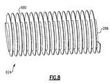
- Figure 8 illustrates another example hollow tube 624, which can be internally similar to any of the examples above.
- the hollow tube 624 also includes a plurality of protrusions 660 extending outwardly from the exterior surface 26b.
- the protrusions 660 increase surface area and thus further promote heat transfer.
- the protrusions 660 can be fins, pins, or combinations thereof, but are not limited to such structures.
Landscapes
- Physics & Mathematics (AREA)
- Engineering & Computer Science (AREA)
- Geometry (AREA)
- Thermal Sciences (AREA)
- Mechanical Engineering (AREA)
- General Engineering & Computer Science (AREA)
- Heat-Exchange Devices With Radiators And Conduit Assemblies (AREA)
- Powder Metallurgy (AREA)
Applications Claiming Priority (1)
| Application Number | Priority Date | Filing Date | Title |
|---|---|---|---|
| US14/616,819 US20160231065A1 (en) | 2015-02-09 | 2015-02-09 | Heat exchanger article with hollow tube having plurality of vanes |
Publications (2)
| Publication Number | Publication Date |
|---|---|
| EP3054253A1 true EP3054253A1 (fr) | 2016-08-10 |
| EP3054253B1 EP3054253B1 (fr) | 2019-04-03 |
Family
ID=55486466
Family Applications (1)
| Application Number | Title | Priority Date | Filing Date |
|---|---|---|---|
| EP16154908.4A Active EP3054253B1 (fr) | 2015-02-09 | 2016-02-09 | Article d'échangeur de chaleur à tube creux ayant une pluralité d'aubes |
Country Status (2)
| Country | Link |
|---|---|
| US (1) | US20160231065A1 (fr) |
| EP (1) | EP3054253B1 (fr) |
Families Citing this family (4)
| Publication number | Priority date | Publication date | Assignee | Title |
|---|---|---|---|---|
| EP3348947B1 (fr) | 2017-01-13 | 2020-11-04 | HS Marston Aerospace Limited | Échangeur de chaleur |
| US11009271B2 (en) * | 2018-10-25 | 2021-05-18 | Heatcraft Refrigeration Products Llc | Evaporator coil insert |
| CN114413675B (zh) * | 2021-12-15 | 2023-10-13 | 合肥通用机械研究院有限公司 | 一种内表面具有Laval结构的管道及其增材制造方法 |
| EP4517247A1 (fr) * | 2023-08-31 | 2025-03-05 | Carrier Corporation | Distributeur de fluide pour échangeur de chaleur à microcanaux |
Citations (3)
| Publication number | Priority date | Publication date | Assignee | Title |
|---|---|---|---|---|
| GB1359647A (en) * | 1971-10-12 | 1974-07-10 | Dewandre Co Ltd C | Heat transfer tubes |
| US20110094721A1 (en) * | 2009-10-28 | 2011-04-28 | Asia Vital Components Co., Ltd. | Heat exchanger structure |
| WO2014125260A1 (fr) * | 2013-02-12 | 2014-08-21 | Ray Newton | Appareil d'optimisation d'échangeur de chaleur et procédé pour son utilisation |
Family Cites Families (17)
| Publication number | Priority date | Publication date | Assignee | Title |
|---|---|---|---|---|
| US1324714A (en) * | 1913-07-02 | 1919-12-09 | Robert Allen | Method of manufacturing metal tubes. |
| US1880533A (en) * | 1932-02-03 | 1932-10-04 | Servel Sales Inc | Heat exchanger |
| US3297305A (en) * | 1957-08-14 | 1967-01-10 | Willie W Walden | Fluid mixing apparatus |
| US4109318A (en) * | 1977-04-15 | 1978-08-22 | General Signal Corporation | Fluid injection and sampling device for an in-line blender |
| JPS54101539A (en) * | 1978-01-27 | 1979-08-10 | Kobe Steel Ltd | Heat exchange pipe for use with water-sprinkling type, panel-shaped, liquefied natural gas evaporator and combination of such pipes and their manufacturing method |
| CH664505A5 (de) * | 1984-03-05 | 1988-03-15 | Sulzer Ag | Statische mischeinrichtung, insbesondere fuer hochviskose kunststoffschmelzen verarbeitende maschinen. |
| US5307867A (en) * | 1992-08-10 | 1994-05-03 | Noritake Co., Limited | Heat exchanger |
| US5655599A (en) * | 1995-06-21 | 1997-08-12 | Gas Research Institute | Radiant tubes having internal fins |
| US5915463A (en) * | 1996-03-23 | 1999-06-29 | Motorola, Inc. | Heat dissipation apparatus and method |
| US5992465A (en) * | 1996-08-02 | 1999-11-30 | Jansen; Robert C. | Flow system for pipes, pipe fittings, ducts and ducting elements |
| JP2000146482A (ja) * | 1998-09-16 | 2000-05-26 | China Petrochem Corp | 熱交換器チュ―ブ、その製造方法、及びその熱交換器チュ―ブを用いるクラッキング炉又は他の管状加熱炉 |
| DE10038624C2 (de) * | 2000-08-03 | 2002-11-21 | Broekelmann Aluminium F W | Wärmeübertragungsrohr mit gedrallten Innenrippen |
| US7416404B2 (en) * | 2005-04-18 | 2008-08-26 | General Electric Company | Feed injector for gasification and related method |
| US20080271877A1 (en) * | 2007-02-21 | 2008-11-06 | Gerald Glass | Apparatus for multi-tube heat exchanger with turbulence promoters |
| US20080236803A1 (en) * | 2007-03-27 | 2008-10-02 | Wolverine Tube, Inc. | Finned tube with indentations |
| ITTO20110535A1 (it) * | 2011-06-20 | 2012-12-21 | Cornaglia G Off Met Spa | Miscelatore statico per il trattamento di gas di scarico e suo metodo di fabbricazione. |
| US9752835B2 (en) * | 2013-06-06 | 2017-09-05 | Honeywell International Inc. | Unitary heat exchangers having integrally-formed compliant heat exchanger tubes and heat exchange systems including the same |
-
2015
- 2015-02-09 US US14/616,819 patent/US20160231065A1/en not_active Abandoned
-
2016
- 2016-02-09 EP EP16154908.4A patent/EP3054253B1/fr active Active
Patent Citations (3)
| Publication number | Priority date | Publication date | Assignee | Title |
|---|---|---|---|---|
| GB1359647A (en) * | 1971-10-12 | 1974-07-10 | Dewandre Co Ltd C | Heat transfer tubes |
| US20110094721A1 (en) * | 2009-10-28 | 2011-04-28 | Asia Vital Components Co., Ltd. | Heat exchanger structure |
| WO2014125260A1 (fr) * | 2013-02-12 | 2014-08-21 | Ray Newton | Appareil d'optimisation d'échangeur de chaleur et procédé pour son utilisation |
Also Published As
| Publication number | Publication date |
|---|---|
| EP3054253B1 (fr) | 2019-04-03 |
| US20160231065A1 (en) | 2016-08-11 |
Similar Documents
| Publication | Publication Date | Title |
|---|---|---|
| JP6636575B2 (ja) | 積層造形された熱交換器 | |
| EP2781872B1 (fr) | Conception et de fabrication d'échangeur de chaleur | |
| CN112400092B (zh) | 具有带挡板单元的三维晶格结构的热交换器和在热交换器的三维晶格结构中形成挡板的方法 | |
| CN109798800A (zh) | 波形壁热交换器 | |
| EP3054253B1 (fr) | Article d'échangeur de chaleur à tube creux ayant une pluralité d'aubes | |
| US9528632B2 (en) | Tortuous path control valve trim | |
| US9713843B2 (en) | Method for additively constructing internal channels | |
| JP3866226B2 (ja) | マイクロサーキット | |
| US9764435B2 (en) | Counter-flow heat exchange systems | |
| US11213923B2 (en) | Heat exchangers having a three-dimensional lattice structure with a rounded unit cell entrance and methods of forming rounded unit cell entrances in a three-dimensional lattice structure of a heat exchanger | |
| US10821509B2 (en) | Additive heat exchanger mixing chambers | |
| CN110446840A (zh) | 管状阵列热交换器 | |
| US20190024988A1 (en) | Header assembly for a heat exchanger | |
| CN109477580B (zh) | 流量阻尼器及其制造方法 | |
| JP6816997B2 (ja) | 物品及び物品の形成方法 | |
| US20210222966A1 (en) | Heat exchangers | |
| EP3348947B1 (fr) | Échangeur de chaleur | |
| CN106907187A (zh) | 制品及形成制品的方法 | |
| EP2841707B1 (fr) | Surface portante dotée de nervures à distance minimale et procédé de traitement d'une lame | |
| CN108431533B (zh) | 管体及制造方法 | |
| US20170356692A1 (en) | Finned Heat Exchanger | |
| CN106679460B (zh) | 一种微通道换热器 | |
| CN206739932U (zh) | 一种微通道换热器 | |
| JP2024510980A (ja) | 羽根車のハイブリッド製造 | |
| US20230071781A1 (en) | Radiant tube |
Legal Events
| Date | Code | Title | Description |
|---|---|---|---|
| PUAI | Public reference made under article 153(3) epc to a published international application that has entered the european phase |
Free format text: ORIGINAL CODE: 0009012 |
|
| AK | Designated contracting states |
Kind code of ref document: A1 Designated state(s): AL AT BE BG CH CY CZ DE DK EE ES FI FR GB GR HR HU IE IS IT LI LT LU LV MC MK MT NL NO PL PT RO RS SE SI SK SM TR |
|
| AX | Request for extension of the european patent |
Extension state: BA ME |
|
| RAP1 | Party data changed (applicant data changed or rights of an application transferred) |
Owner name: UNITED TECHNOLOGIES CORPORATION |
|
| STAA | Information on the status of an ep patent application or granted ep patent |
Free format text: STATUS: REQUEST FOR EXAMINATION WAS MADE |
|
| 17P | Request for examination filed |
Effective date: 20170210 |
|
| RBV | Designated contracting states (corrected) |
Designated state(s): AL AT BE BG CH CY CZ DE DK EE ES FI FR GB GR HR HU IE IS IT LI LT LU LV MC MK MT NL NO PL PT RO RS SE SI SK SM TR |
|
| GRAP | Despatch of communication of intention to grant a patent |
Free format text: ORIGINAL CODE: EPIDOSNIGR1 |
|
| STAA | Information on the status of an ep patent application or granted ep patent |
Free format text: STATUS: GRANT OF PATENT IS INTENDED |
|
| INTG | Intention to grant announced |
Effective date: 20181012 |
|
| GRAS | Grant fee paid |
Free format text: ORIGINAL CODE: EPIDOSNIGR3 |
|
| GRAA | (expected) grant |
Free format text: ORIGINAL CODE: 0009210 |
|
| STAA | Information on the status of an ep patent application or granted ep patent |
Free format text: STATUS: THE PATENT HAS BEEN GRANTED |
|
| AK | Designated contracting states |
Kind code of ref document: B1 Designated state(s): AL AT BE BG CH CY CZ DE DK EE ES FI FR GB GR HR HU IE IS IT LI LT LU LV MC MK MT NL NO PL PT RO RS SE SI SK SM TR |
|
| REG | Reference to a national code |
Ref country code: GB Ref legal event code: FG4D |
|
| REG | Reference to a national code |
Ref country code: CH Ref legal event code: EP Ref country code: AT Ref legal event code: REF Ref document number: 1116259 Country of ref document: AT Kind code of ref document: T Effective date: 20190415 |
|
| REG | Reference to a national code |
Ref country code: DE Ref legal event code: R096 Ref document number: 602016011734 Country of ref document: DE |
|
| REG | Reference to a national code |
Ref country code: IE Ref legal event code: FG4D |
|
| REG | Reference to a national code |
Ref country code: NL Ref legal event code: MP Effective date: 20190403 |
|
| REG | Reference to a national code |
Ref country code: LT Ref legal event code: MG4D |
|
| REG | Reference to a national code |
Ref country code: AT Ref legal event code: MK05 Ref document number: 1116259 Country of ref document: AT Kind code of ref document: T Effective date: 20190403 |
|
| PG25 | Lapsed in a contracting state [announced via postgrant information from national office to epo] |
Ref country code: NL Free format text: LAPSE BECAUSE OF FAILURE TO SUBMIT A TRANSLATION OF THE DESCRIPTION OR TO PAY THE FEE WITHIN THE PRESCRIBED TIME-LIMIT Effective date: 20190403 |
|
| PG25 | Lapsed in a contracting state [announced via postgrant information from national office to epo] |
Ref country code: NO Free format text: LAPSE BECAUSE OF FAILURE TO SUBMIT A TRANSLATION OF THE DESCRIPTION OR TO PAY THE FEE WITHIN THE PRESCRIBED TIME-LIMIT Effective date: 20190703 Ref country code: LT Free format text: LAPSE BECAUSE OF FAILURE TO SUBMIT A TRANSLATION OF THE DESCRIPTION OR TO PAY THE FEE WITHIN THE PRESCRIBED TIME-LIMIT Effective date: 20190403 Ref country code: FI Free format text: LAPSE BECAUSE OF FAILURE TO SUBMIT A TRANSLATION OF THE DESCRIPTION OR TO PAY THE FEE WITHIN THE PRESCRIBED TIME-LIMIT Effective date: 20190403 Ref country code: SE Free format text: LAPSE BECAUSE OF FAILURE TO SUBMIT A TRANSLATION OF THE DESCRIPTION OR TO PAY THE FEE WITHIN THE PRESCRIBED TIME-LIMIT Effective date: 20190403 Ref country code: HR Free format text: LAPSE BECAUSE OF FAILURE TO SUBMIT A TRANSLATION OF THE DESCRIPTION OR TO PAY THE FEE WITHIN THE PRESCRIBED TIME-LIMIT Effective date: 20190403 Ref country code: PT Free format text: LAPSE BECAUSE OF FAILURE TO SUBMIT A TRANSLATION OF THE DESCRIPTION OR TO PAY THE FEE WITHIN THE PRESCRIBED TIME-LIMIT Effective date: 20190803 Ref country code: ES Free format text: LAPSE BECAUSE OF FAILURE TO SUBMIT A TRANSLATION OF THE DESCRIPTION OR TO PAY THE FEE WITHIN THE PRESCRIBED TIME-LIMIT Effective date: 20190403 Ref country code: AL Free format text: LAPSE BECAUSE OF FAILURE TO SUBMIT A TRANSLATION OF THE DESCRIPTION OR TO PAY THE FEE WITHIN THE PRESCRIBED TIME-LIMIT Effective date: 20190403 Ref country code: CZ Free format text: LAPSE BECAUSE OF FAILURE TO SUBMIT A TRANSLATION OF THE DESCRIPTION OR TO PAY THE FEE WITHIN THE PRESCRIBED TIME-LIMIT Effective date: 20190403 |
|
| PG25 | Lapsed in a contracting state [announced via postgrant information from national office to epo] |
Ref country code: BG Free format text: LAPSE BECAUSE OF FAILURE TO SUBMIT A TRANSLATION OF THE DESCRIPTION OR TO PAY THE FEE WITHIN THE PRESCRIBED TIME-LIMIT Effective date: 20190703 Ref country code: RS Free format text: LAPSE BECAUSE OF FAILURE TO SUBMIT A TRANSLATION OF THE DESCRIPTION OR TO PAY THE FEE WITHIN THE PRESCRIBED TIME-LIMIT Effective date: 20190403 Ref country code: PL Free format text: LAPSE BECAUSE OF FAILURE TO SUBMIT A TRANSLATION OF THE DESCRIPTION OR TO PAY THE FEE WITHIN THE PRESCRIBED TIME-LIMIT Effective date: 20190403 Ref country code: LV Free format text: LAPSE BECAUSE OF FAILURE TO SUBMIT A TRANSLATION OF THE DESCRIPTION OR TO PAY THE FEE WITHIN THE PRESCRIBED TIME-LIMIT Effective date: 20190403 Ref country code: GR Free format text: LAPSE BECAUSE OF FAILURE TO SUBMIT A TRANSLATION OF THE DESCRIPTION OR TO PAY THE FEE WITHIN THE PRESCRIBED TIME-LIMIT Effective date: 20190704 |
|
| PG25 | Lapsed in a contracting state [announced via postgrant information from national office to epo] |
Ref country code: IS Free format text: LAPSE BECAUSE OF FAILURE TO SUBMIT A TRANSLATION OF THE DESCRIPTION OR TO PAY THE FEE WITHIN THE PRESCRIBED TIME-LIMIT Effective date: 20190803 Ref country code: AT Free format text: LAPSE BECAUSE OF FAILURE TO SUBMIT A TRANSLATION OF THE DESCRIPTION OR TO PAY THE FEE WITHIN THE PRESCRIBED TIME-LIMIT Effective date: 20190403 |
|
| REG | Reference to a national code |
Ref country code: DE Ref legal event code: R097 Ref document number: 602016011734 Country of ref document: DE |
|
| PG25 | Lapsed in a contracting state [announced via postgrant information from national office to epo] |
Ref country code: SK Free format text: LAPSE BECAUSE OF FAILURE TO SUBMIT A TRANSLATION OF THE DESCRIPTION OR TO PAY THE FEE WITHIN THE PRESCRIBED TIME-LIMIT Effective date: 20190403 Ref country code: DK Free format text: LAPSE BECAUSE OF FAILURE TO SUBMIT A TRANSLATION OF THE DESCRIPTION OR TO PAY THE FEE WITHIN THE PRESCRIBED TIME-LIMIT Effective date: 20190403 Ref country code: EE Free format text: LAPSE BECAUSE OF FAILURE TO SUBMIT A TRANSLATION OF THE DESCRIPTION OR TO PAY THE FEE WITHIN THE PRESCRIBED TIME-LIMIT Effective date: 20190403 Ref country code: RO Free format text: LAPSE BECAUSE OF FAILURE TO SUBMIT A TRANSLATION OF THE DESCRIPTION OR TO PAY THE FEE WITHIN THE PRESCRIBED TIME-LIMIT Effective date: 20190403 |
|
| PLBE | No opposition filed within time limit |
Free format text: ORIGINAL CODE: 0009261 |
|
| STAA | Information on the status of an ep patent application or granted ep patent |
Free format text: STATUS: NO OPPOSITION FILED WITHIN TIME LIMIT |
|
| PG25 | Lapsed in a contracting state [announced via postgrant information from national office to epo] |
Ref country code: SM Free format text: LAPSE BECAUSE OF FAILURE TO SUBMIT A TRANSLATION OF THE DESCRIPTION OR TO PAY THE FEE WITHIN THE PRESCRIBED TIME-LIMIT Effective date: 20190403 Ref country code: IT Free format text: LAPSE BECAUSE OF FAILURE TO SUBMIT A TRANSLATION OF THE DESCRIPTION OR TO PAY THE FEE WITHIN THE PRESCRIBED TIME-LIMIT Effective date: 20190403 |
|
| 26N | No opposition filed |
Effective date: 20200106 |
|
| PG25 | Lapsed in a contracting state [announced via postgrant information from national office to epo] |
Ref country code: TR Free format text: LAPSE BECAUSE OF FAILURE TO SUBMIT A TRANSLATION OF THE DESCRIPTION OR TO PAY THE FEE WITHIN THE PRESCRIBED TIME-LIMIT Effective date: 20190403 |
|
| PG25 | Lapsed in a contracting state [announced via postgrant information from national office to epo] |
Ref country code: SI Free format text: LAPSE BECAUSE OF FAILURE TO SUBMIT A TRANSLATION OF THE DESCRIPTION OR TO PAY THE FEE WITHIN THE PRESCRIBED TIME-LIMIT Effective date: 20190403 |
|
| REG | Reference to a national code |
Ref country code: CH Ref legal event code: PL |
|
| REG | Reference to a national code |
Ref country code: BE Ref legal event code: MM Effective date: 20200229 |
|
| PG25 | Lapsed in a contracting state [announced via postgrant information from national office to epo] |
Ref country code: MC Free format text: LAPSE BECAUSE OF FAILURE TO SUBMIT A TRANSLATION OF THE DESCRIPTION OR TO PAY THE FEE WITHIN THE PRESCRIBED TIME-LIMIT Effective date: 20190403 Ref country code: LU Free format text: LAPSE BECAUSE OF NON-PAYMENT OF DUE FEES Effective date: 20200209 |
|
| PG25 | Lapsed in a contracting state [announced via postgrant information from national office to epo] |
Ref country code: LI Free format text: LAPSE BECAUSE OF NON-PAYMENT OF DUE FEES Effective date: 20200229 Ref country code: CH Free format text: LAPSE BECAUSE OF NON-PAYMENT OF DUE FEES Effective date: 20200229 |
|
| PG25 | Lapsed in a contracting state [announced via postgrant information from national office to epo] |
Ref country code: IE Free format text: LAPSE BECAUSE OF NON-PAYMENT OF DUE FEES Effective date: 20200209 |
|
| PG25 | Lapsed in a contracting state [announced via postgrant information from national office to epo] |
Ref country code: BE Free format text: LAPSE BECAUSE OF NON-PAYMENT OF DUE FEES Effective date: 20200229 |
|
| PG25 | Lapsed in a contracting state [announced via postgrant information from national office to epo] |
Ref country code: MT Free format text: LAPSE BECAUSE OF FAILURE TO SUBMIT A TRANSLATION OF THE DESCRIPTION OR TO PAY THE FEE WITHIN THE PRESCRIBED TIME-LIMIT Effective date: 20190403 Ref country code: CY Free format text: LAPSE BECAUSE OF FAILURE TO SUBMIT A TRANSLATION OF THE DESCRIPTION OR TO PAY THE FEE WITHIN THE PRESCRIBED TIME-LIMIT Effective date: 20190403 |
|
| PG25 | Lapsed in a contracting state [announced via postgrant information from national office to epo] |
Ref country code: MK Free format text: LAPSE BECAUSE OF FAILURE TO SUBMIT A TRANSLATION OF THE DESCRIPTION OR TO PAY THE FEE WITHIN THE PRESCRIBED TIME-LIMIT Effective date: 20190403 |
|
| REG | Reference to a national code |
Ref country code: DE Ref legal event code: R081 Ref document number: 602016011734 Country of ref document: DE Owner name: RAYTHEON TECHNOLOGIES CORPORATION (N.D.GES.D.S, US Free format text: FORMER OWNER: UNITED TECHNOLOGIES CORPORATION, FARMINGTON, CONN., US Ref country code: DE Ref legal event code: R081 Ref document number: 602016011734 Country of ref document: DE Owner name: RTX CORPORATION (N.D.GES.D. STAATES DELAWARE),, US Free format text: FORMER OWNER: UNITED TECHNOLOGIES CORPORATION, FARMINGTON, CONN., US |
|
| P01 | Opt-out of the competence of the unified patent court (upc) registered |
Effective date: 20230520 |
|
| REG | Reference to a national code |
Ref country code: DE Ref legal event code: R081 Ref document number: 602016011734 Country of ref document: DE Owner name: RTX CORPORATION (N.D.GES.D. STAATES DELAWARE),, US Free format text: FORMER OWNER: RAYTHEON TECHNOLOGIES CORPORATION (N.D.GES.D.STAATES DELAWARE), ARLINGTON, VA, US |
|
| PGFP | Annual fee paid to national office [announced via postgrant information from national office to epo] |
Ref country code: GB Payment date: 20260122 Year of fee payment: 11 |
|
| PGFP | Annual fee paid to national office [announced via postgrant information from national office to epo] |
Ref country code: DE Payment date: 20260121 Year of fee payment: 11 |
|
| PGFP | Annual fee paid to national office [announced via postgrant information from national office to epo] |
Ref country code: FR Payment date: 20260121 Year of fee payment: 11 |