EP3054532B1 - Bloc terminal pour connecter fils electriques avec multifunctionelle tableau électrique - Google Patents
Bloc terminal pour connecter fils electriques avec multifunctionelle tableau électrique Download PDFInfo
- Publication number
- EP3054532B1 EP3054532B1 EP16154009.1A EP16154009A EP3054532B1 EP 3054532 B1 EP3054532 B1 EP 3054532B1 EP 16154009 A EP16154009 A EP 16154009A EP 3054532 B1 EP3054532 B1 EP 3054532B1
- Authority
- EP
- European Patent Office
- Prior art keywords
- terminal block
- vertical
- jumper
- longitudinal direction
- screw
- Prior art date
- Legal status (The legal status is an assumption and is not a legal conclusion. Google has not performed a legal analysis and makes no representation as to the accuracy of the status listed.)
- Active
Links
Images

Classifications
-
- H—ELECTRICITY
- H01—ELECTRIC ELEMENTS
- H01R—ELECTRICALLY-CONDUCTIVE CONNECTIONS; STRUCTURAL ASSOCIATIONS OF A PLURALITY OF MUTUALLY-INSULATED ELECTRICAL CONNECTING ELEMENTS; COUPLING DEVICES; CURRENT COLLECTORS
- H01R9/00—Structural associations of a plurality of mutually-insulated electrical connecting elements, e.g. terminal strips or terminal blocks; Terminals or binding posts mounted upon a base or in a case; Bases therefor
- H01R9/22—Bases, e.g. strip, block, panel
- H01R9/24—Terminal blocks
- H01R9/26—Clip-on terminal blocks for side-by-side rail- or strip-mounting
- H01R9/2625—Clip-on terminal blocks for side-by-side rail- or strip-mounting with built-in electrical component
-
- H—ELECTRICITY
- H01—ELECTRIC ELEMENTS
- H01R—ELECTRICALLY-CONDUCTIVE CONNECTIONS; STRUCTURAL ASSOCIATIONS OF A PLURALITY OF MUTUALLY-INSULATED ELECTRICAL CONNECTING ELEMENTS; COUPLING DEVICES; CURRENT COLLECTORS
- H01R9/00—Structural associations of a plurality of mutually-insulated electrical connecting elements, e.g. terminal strips or terminal blocks; Terminals or binding posts mounted upon a base or in a case; Bases therefor
- H01R9/22—Bases, e.g. strip, block, panel
- H01R9/24—Terminal blocks
- H01R9/26—Clip-on terminal blocks for side-by-side rail- or strip-mounting
- H01R9/2675—Electrical interconnections between two blocks, e.g. by means of busbars
-
- H—ELECTRICITY
- H01—ELECTRIC ELEMENTS
- H01R—ELECTRICALLY-CONDUCTIVE CONNECTIONS; STRUCTURAL ASSOCIATIONS OF A PLURALITY OF MUTUALLY-INSULATED ELECTRICAL CONNECTING ELEMENTS; COUPLING DEVICES; CURRENT COLLECTORS
- H01R13/00—Details of coupling devices of the kinds covered by groups H01R12/70 or H01R24/00 - H01R33/00
- H01R13/62—Means for facilitating engagement or disengagement of coupling parts or for holding them in engagement
- H01R13/627—Snap or like fastening
- H01R13/6271—Latching means integral with the housing
- H01R13/6273—Latching means integral with the housing comprising two latching arms
Definitions
- the present invention relates to a switchboard multifunction terminal block for connecting electrical wires.
- terminal blocks designed to be mounted on associated supports and to provide on the front side access to the retaining means - normally of the screw or spring type - for electrical wires to be connected in order to ensure continuity of the electric circuit section; said continuity being achieved by inserting inside a special seat, accessible from the top side, movable contact elements such as protection fuses, electric circuit breakers or jumpers for connecting together two adjacent terminal blocks. It is also known that these jumpers may be:
- the two types have different dimensional measurements both in the transverse width/thickness direction of the terminal block and in the longitudinal lengthwise direction of the terminal block.
- EP 0 760 539 A2 describes a terminal block according to the preamble of Claim 1, with a first space (14) centred on the vertical longitudinal access and bounded in the longitudinal direction (X-X) by respective partitions extending in the vertical direction (Y-Y) by an amount such as to allow the insertion of a jumper of the screw type with L-shaped body or alternatively a pair of jumpers of the type with spring lugs specially designed for said central space.
- EP 2 204 886 A1 describes a terminal block with a central space divided into two sub-spaces by a central dividing wall for receiving the separate legs of a shunt which may be for example a fuse, a relay or a signalling lamp.
- US 2011/ 014808 describes a jumper having two mutually insulated contact elements arranged in a housing, that can be swtiched from a first position in which the contact zones do not contact the contact elements into a second final position in which the contact elements are interconnected in an electrically conducting manner.
- a terminal block with three identical adjacent spaces for housing contact elements of the jumper is also shown.
- the technical problem which is posed therefore is that of providing a terminal block, in particular of the type for switchboards designed for wired circuits, which allows the insertion equally well of both screw jumpers and spring jumpers, also simultaneously, without having to replace the terminal block when there is a variation in the type of contact to be inserted.
- this terminal block should have standard dimensions, so that the various types of terminal blocks can be classified in the same size categories and can be produced and assembled in an easy and low-cost manner, and that it should be designed to avoid errors during insertion of the different electrical contact jumpers with the consequent possibility of damaging the connected circuits.
- a terminal block for connecting electrical wires and designed to house, also simultaneously, jumpers of the spring and/or screw type, according to the features of Claim 1.
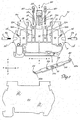
- the terminal block according to the present invention comprises an insulating body 10 forming the container of the means (50) ( Fig. 2 ) for retaining the free ends 2a of electrical wires 2.
- the terminal block may be completed so as to form the various electrical connections in the longitudinal direction X-X between the opposite wires 2 or in the transverse direction with other adjacent terminal blocks, respectively, by means of:
- said insulating body 10 has a frame 11 substantially in the form of a closed ring and formed so as to define at least one top side 11a and at least two respective flanks 11b arranged opposite to each other in the longitudinal direction X-X.
- the body 10 has, formed inside it, at least:
- the top wall 11a of the frame 11 may also be provided with (see Fig. 4 ):
- the terminal block also comprises:
- the screw-type jumper 30 and spring-lug jumper 40 are not described in detail since they are of the conventional type.
- the terminal block has an undercut 16 with a base 16a provided with a first central opening 16b and two second lateral openings 16c arranged on opposite sides of the central opening 16b.
- the three openings 16b and 16c form the openings towards the top side 11a of the first space 14 and the pair of spaces 15, respectively, for insertion, in the vertical direction Z-Z, of the respective screw jumper 30 with conductor body and/or spring-lug jumper 40, via the top side 11a accessible for the operator also once the terminal block has been mounted on the electric switchboard.
- Each side wall 11b of the frame 11 is provided with a respective opening 17 for introducing the wire 2 in the longitudinal direction X-X.
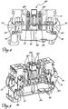
- the opposite free ends of the lamina 110 form a tip 22 inclined upwards and designed to engage with a corresponding internal seat 18 provided on each flank 11b of the frame 11 so as to stably fasten the conductor lamina 20 to the insulating body 10.
- each tip 22 has an incision 22a designed to engage with a corresponding relief 18a in the seat 18 in order to axially retain the lamina when it undergoes an axial deformation owing to the thrust exerted by the screw of the means for retaining the wire 2.
- the conductor lamina 20 has a first central hole 21, with female thread 21a suitable for mating with the thread of the screw 32 of the jumper 30, and a pair of openings 23 with a polygonal, preferably quadrangular form as shown, arranged preferably in a symmetrical manner on opposite sides of the central hole 21 for connection with the contact lugs 41 of the spring jumper 40.
- the hole 21 and the openings 23 will be respectively coaxial with the spaces 14 and 15 so as to allow the conductive connection with the corresponding jumper 30 or 40, once it has been fully inserted inside the terminal block.
- the central hole 21 is obtained by means of deep-drawing so as to form an extended collar 21b in the vertical direction Z-Z designed to allow better screwing-in of the screw 31 of the jumper 30, further favouring a better conductive contact.
- means 50 for retaining the electric wire 2 are of the clamp type 51 with actuating screw 52; the head 52a of said screw 52 is accessible from the outside by means of the said hole 13a with vertical axis Z-Z through which it is possible to insert the operating tool for rotating the screw, the tip of which, reacting against the surface of the lamina 21, recalls the clamp 41 which grips the end 2a of the wire 2 between clamp and lamina.
- the means for retaining the wire 2 may be of the spring type.
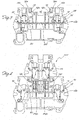
- a second preferred embodiment of the terminal block according to the invention is envisaged, said embodiment having a frame 11 similar to that already described and for which the same reference numbers will be used for parts which remain unchanged.
- each vertical partition 14a bounding the seat 14 has a tooth 14c - which is preferably rigid - extending towards the inside of the seat 14; the two teeth 14c are designed to cooperate with corresponding and complementary teeth 214c - resiliently deformable in the longitudinal direction X-X - of an add-on terminal block 220 which can be mounted on the terminal block according to the invention in the vertical direction Z-Z via the top part thereof.
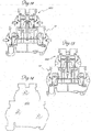
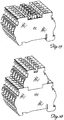
- a third preferred embodiment of the terminal block according to the invention is envisaged, said embodiment having:
- the teeth 19 with respective seat 19a are designed to receive corresponding projections 119 projecting outwards in the longitudinal direction X-X and formed in the bottom part of the frame 111 of an add-on terminal block 100.
- the two frames 11,211 or 11,111 of the two terminal blocks i.e. base terminal block and add-on terminal block, are joined together so as to form a two-tier - i.e. upper tier and lower tier - assembly according to the non-limiting directional layout shown in the figure.
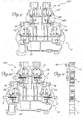
- Both upper-tier terminal blocks 200,100 have a structure similar to that of the lower terminal block, but have a single, small-size, central seat 214,114 for housing a jumper 40 with spring lugs 41; correspondingly the longitudinal conductor lamina 120 has a single polygonal opening 123 for allowing the insertion of the spring lugs 41 and the consequent electrical conduction contact as already described.
- the other parts of the upper terminal block 200,100 are similar to those of the lower terminal block and therefore will not be described in detail, but have lengthwise dimensions in the longitudinal direction X-X and vertical direction Z-Z slightly greater than the undercut 16 in the base terminal block.
- the longitudinal dimension of the upper-tier terminal block 200,100 is such as to leave exposed the hole 12a for access to the screw for actuating the means 50 for gripping the bottom wire 2 against the conducting lamina 20.
- the assembly of the two-tier terminal block is again similar to that of the base terminal block, although it is envisaged that in this case the closing cover 160 ( Fig. 14 ) is formed as one piece so as to close both the upper and lower terminal blocks with a single operating action, thus reducing both the need to diversify the component parts and the management and the duration of the assembly steps.
- terminal block according to the invention is able to house equally well a jumper of the screw type and/or at the same time, at least one, but also two jumpers of the spring-lug type, having dimensions which lie within the standard minimum dimensions.
- the particular configuration of the central hole and the lateral openings in the conductor lamina prevent incorrect assembly operations since the spring-lug jumper would not make contact if inserted inside the threaded hole and the screw jumper screw would not have any grip inside the lateral holes.
Landscapes
- Connections Arranged To Contact A Plurality Of Conductors (AREA)
Claims (5)
- Bornier multifonction de tableau de distribution destiné à connecter des fils électriques (2, 2a), comprenant- un corps isolant (10) formé par un bâti annulaire sensiblement fermé (11) et conçu de façon à définir au moins un côté supérieur (11a) et un côté inférieur, opposés dans une direction verticale (Z-Z), et au moins deux flancs respectifs (11b) opposés dans une direction longitudinale (X-X) ;le corps (10) comporte, formés en son sein :- une première paire de logements (12) situés le plus à l'extérieur dans la direction longitudinale (X-X) en direction des flancs (11b), symétriques par rapport à un axe central vertical (Z-Z), ouverts dans la direction transversale (Y-Y) et communiquant, en utilisation, avec l'extérieur par le biais d'une première ouverture respective (12a) s'étendant dans la direction verticale (Z-Z) jusqu'au côté supérieur (11a) du bâti (11) ; les logements (12) étant conçus pour loger un moyen (50) destiné à saisir des fils (2) qui peuvent être introduits longitudinalement dans les logements (12) à partir des flancs (11b) du bâti (11) ;- un premier espace (14) centré sur l'axe central vertical (Z-Z) et délimité dans la direction longitudinale (X-X) par des premières cloisons respectives (14a) s'étendant dans la direction verticale (Z-Z) et interrompues verticalement le long d'une section dans le sens de la hauteur de façon à permettre l'introduction, dans la direction transversale (Y-Y), d'une lame conductrice longitudinale (20) conçue pour restaurer la continuité électrique entre les fils (2), lesdites premières cloisons (14a) étant espacées l'une de l'autre dans la direction longitudinale (X-X) d'une quantité permettant de définir une taille de l'espace appropriée pour loger un cavalier (30) du type à vis (32) ;la face avant (11a) du bornier comportant une première ouverture centrale (16b) destinée à établir une communication avec l'extérieur du premier espace (14) à des fins d'introduction du cavalier à vis respectif (30) par le biais du côté avant (11a) accessible à l'opérateur ;
dans lequel ladite lame conductrice longitudinale (20) comporte un premier trou central (21) doté d'un filetage femelle conçu pour s'accoupler avec le filetage de la vis (32) du cavalier (30), et une paire d'ouvertures de forme polygonale (23) ménagées symétriquement sur des côtés opposés du trou central (21) par rapport à l'axe vertical,
caractérisé en ce qu'il comprend :- une paire de seconds espaces (15) formés respectivement symétriquement sur des côtés opposés du premier espace (14) par rapport à l'axe central vertical (Z-Z), chaque second espace (15) étant délimité dans la direction longitudinale (X-X) par des secondes cloisons respectives (15a) s'étendant dans la direction verticale (Z-Z) et interrompues dans la même direction le long d'une section dans le sens de la hauteur de façon à permettre l'introduction de la lame conductrice (20) dans la direction transversale (Y-Y) ; les cloisons (15a) étant espacées dans la direction longitudinale (X-X) des premières cloisons (14a) d'une quantité permettant de définir une taille de chaque second espace (15) permettant de loger un cavalier respectif (40) du type à pattes à ressort (41),et en ce que
le côté supérieur (11a) du bornier comporte une découpe (16) dotée d'une base (16a) ;
ladite première ouverture centrale (16b) étant formée sur ladite base (16a) ;
la base (16a) comporte deux secondes ouvertures latérales (16c) ménagées symétriquement sur des côtés opposés de l'ouverture centrale (16b) par rapport à l'axe central vertical (Z-Z) ;
dans lequel chacune des deux ouvertures (16c) établit respectivement une communication avec l'extérieur d'un espace respectif de ladite paire d'espaces (15), de façon à introduire le cavalier respectif à pattes de ressort (40) dans la direction verticale (Z-Z) du côté supérieur (11a) accessible à l'opérateur,
et en ce que ledit trou central (21) et lesdites ouvertures (23) de la lame conductrice longitudinale (20) sont respectivement coaxiaux avec l'espace central (14) et les espaces latéraux (15) à des fins de prise respective avec la vis (31) du cavalier de type à vis et avec les pattes (41) d'un cavalier à ressort respectif (40). - Bornier selon la revendication 1, caractérisé en ce que le trou central (21) comporte un collet embouti (21b) dans la direction verticale (Z-Z) pour permettre un vissage supplémentaire de la vis (31) du cavalier (30).
- Bornier selon l'une quelconque des revendications précédentes, caractérisé en ce qu'il comprend une dent rigide (14c) s'étendant dans la direction longitudinale (X-X) de chaque cloison verticale (14a) vers l'intérieur du logement (14).
- Bornier selon l'une quelconque des revendications 1 à 3, caractérisé ce qu'il comprend une paire de dents (19) sous la forme d'un L retourné formées sur la partie la plus à l'extérieur des bords verticaux opposés (16c) de la découpe (16) dans le bâti (11), les dents (19) formant un logement espacé en forme de L respectif (19a) formé sur le bord vertical respectif (16c) de la découpe (16) à des fins de coopération avec des saillies correspondantes (119) faisant saillie vers l'extérieur dans la direction longitudinale (X-X) et formées dans la partie inférieure du bâti (111) d'un bornier supplémentaire (100) ayant des dimensions dans le sens de la longueur dans la direction longitudinale (X-X) et dans la direction verticale (Z-Z) qui sont inférieures à celles du bornier de base.
- Bornier selon l'une quelconque des revendications précédentes, caractérisé en ce que le côté avant visible (11a) comprend des trous (13a) à axe vertical (Z-Z) permettant l'introduction d'une étiquette/indicateur d'identification des connexions de circuit.
Priority Applications (1)
| Application Number | Priority Date | Filing Date | Title |
|---|---|---|---|
| PL16154009T PL3054532T3 (pl) | 2015-02-05 | 2016-02-03 | Wielofunkcyjny zespół listew zaciskowych tablicy rozdzielczej do podłączania przewodów elektrycznych |
Applications Claiming Priority (1)
| Application Number | Priority Date | Filing Date | Title |
|---|---|---|---|
| ITMI20150150 | 2015-02-05 |
Publications (2)
| Publication Number | Publication Date |
|---|---|
| EP3054532A1 EP3054532A1 (fr) | 2016-08-10 |
| EP3054532B1 true EP3054532B1 (fr) | 2018-08-15 |
Family
ID=52781169
Family Applications (1)
| Application Number | Title | Priority Date | Filing Date |
|---|---|---|---|
| EP16154009.1A Active EP3054532B1 (fr) | 2015-02-05 | 2016-02-03 | Bloc terminal pour connecter fils electriques avec multifunctionelle tableau électrique |
Country Status (3)
| Country | Link |
|---|---|
| US (1) | US9634406B2 (fr) |
| EP (1) | EP3054532B1 (fr) |
| PL (1) | PL3054532T3 (fr) |
Families Citing this family (7)
| Publication number | Priority date | Publication date | Assignee | Title |
|---|---|---|---|---|
| EP3054533B1 (fr) * | 2015-02-05 | 2020-01-29 | Morsettitalia S.p.A. | Borne de base et borne auxiliaire pour tableau de connexion et borne à deux niveaux comprenant une borne de base et une borne auxiliaire |
| DE202015100696U1 (de) * | 2015-02-12 | 2016-05-13 | Weidmüller Interface GmbH & Co. KG | Anordnung mehrerer Rastfüße für eine Baugruppe und Baugruppe |
| DE102015121057A1 (de) * | 2015-12-03 | 2017-06-08 | Phoenix Contact Gmbh & Co. Kg | Elektrische Klemme |
| JP6433420B2 (ja) * | 2015-12-25 | 2018-12-05 | 本田技研工業株式会社 | トルクセンサの端子台構造 |
| DE202016101051U1 (de) * | 2016-02-29 | 2017-05-30 | Wago Verwaltungsgesellschaft Mbh | Reihenklemme |
| CN207116731U (zh) * | 2017-06-26 | 2018-03-16 | 泰科电子(上海)有限公司 | 电连接器 |
| PL3425742T3 (pl) * | 2017-07-07 | 2023-09-25 | Morsettitalia S.P.A. | Blok zaciskowy elektrycznej tablicy rozdzielczej z wieloma gniazdami na etykiety |
Family Cites Families (11)
| Publication number | Priority date | Publication date | Assignee | Title |
|---|---|---|---|---|
| US3665376A (en) * | 1970-12-23 | 1972-05-23 | Teledyne Mid America Corp | Terminal block and method of making the same |
| FR2732518B1 (fr) * | 1995-03-29 | 1997-04-30 | Entrelec Sa | Agencement de connexion pour fils conducteurs electriques et module, notamment de type bloc de jonction, equipe d'un tel agencement |
| DE29514014U1 (de) | 1995-09-01 | 1995-10-19 | Weidmüller Interface GmbH & Co, 32760 Detmold | Reihenklemme mit Stromschiene |
| DE102005040657A1 (de) * | 2005-08-26 | 2007-03-15 | Phoenix Contact Gmbh & Co. Kg | Elektrische Anschlussklemme |
| ITMI20061496A1 (it) * | 2006-07-28 | 2008-01-29 | Morsettitalia Spa | Morsetto con elemento conduttore a forma di u per il collegamento di fili elettrici |
| EP1953869B1 (fr) * | 2007-02-05 | 2014-07-30 | Morsettitalia S.p.A. | Bloc terminal doté d'une partie de mâchoire pour venir en prise avec la broche plate des contacts électriques amovibles |
| DE102008014179B4 (de) * | 2008-03-14 | 2012-08-02 | Phoenix Contact Gmbh & Co. Kg | Schaltbrücke und Baueinheit aus mindestens zwei elektrischen Reihenklemmen und einer Schaltbrücke |
| FR2940860B1 (fr) | 2009-01-06 | 2011-03-11 | Abb France | Shunt electrique |
| DE102009017266A1 (de) * | 2009-01-30 | 2010-08-05 | Weidmüller Interface GmbH & Co. KG | Verfahren und Vorrichtung zum Markieren von Reihenklemmen |
| DE202010009293U1 (de) | 2010-06-19 | 2011-11-02 | Weidmüller Interface GmbH & Co. KG | Reihenklemme |
| DE102011118524A1 (de) * | 2011-11-15 | 2013-05-16 | Ellenberger & Poensgen Gmbh | Steckbare Gerätekombination |
-
2016
- 2016-02-03 PL PL16154009T patent/PL3054532T3/pl unknown
- 2016-02-03 EP EP16154009.1A patent/EP3054532B1/fr active Active
- 2016-02-05 US US15/016,660 patent/US9634406B2/en active Active
Non-Patent Citations (1)
| Title |
|---|
| None * |
Also Published As
| Publication number | Publication date |
|---|---|
| US20160233593A1 (en) | 2016-08-11 |
| EP3054532A1 (fr) | 2016-08-10 |
| US9634406B2 (en) | 2017-04-25 |
| PL3054532T3 (pl) | 2019-01-31 |
Similar Documents
| Publication | Publication Date | Title |
|---|---|---|
| EP3054533B1 (fr) | Borne de base et borne auxiliaire pour tableau de connexion et borne à deux niveaux comprenant une borne de base et une borne auxiliaire | |
| EP3054532B1 (fr) | Bloc terminal pour connecter fils electriques avec multifunctionelle tableau électrique | |
| US7892032B2 (en) | Terminal block with jaw part for engagement with the flat pin of movable electric contacts | |
| EP1883132B1 (fr) | Plaque à bornes avec une pièce conductrice en forme de U pour connecter des fils électriques | |
| US7753739B2 (en) | Electrical terminal block | |
| KR101160274B1 (ko) | 커넥터를 구비하는 단자 블록 | |
| KR100910100B1 (ko) | 전기기기의 단자 장치 | |
| CA2968873C (fr) | Dispositifs electriques avec entrees de conducteur electrique longitudinales | |
| WO2013069525A1 (fr) | Module de câblage de batterie | |
| CN111033908B (zh) | 具有保持框架和可附接在该保持框架上的模块化接触嵌件的插式连接器部件的组件 | |
| EP3054531B1 (fr) | Élément conducteur de connexion à terre pour block terminal de tableau electrique et le correspondant block terminal pour câbles de mis à terre | |
| HK1250423A1 (zh) | 配电设备 | |
| AU2019480471B2 (en) | Four pole outgoing plugging assembly | |
| EP2348582B1 (fr) | Pièce conductrice ayant la forme d'un U inversé comprenant des moyens de contact électrique et des moyens de maintien mécanique de plusieurs dispositifs électriques, et bornier comprenant ladite pièce conductrice. | |
| US8911267B2 (en) | Container for electrical/electronic circuits provided with seats and associated contact elements for electrical wiring connectors | |
| US20150349476A1 (en) | Multiport terminal with current bars | |
| AU2020289801A1 (en) | Patch panel arrangments, cable terminating devices & methods | |
| ITTO940251A1 (it) | Basetta di presa di corrente | |
| KR20170011372A (ko) | 커넥터 단자 | |
| JP2015135769A (ja) | ジョイントコネクタ、ジョイントコネクタの接続構造、及びジョイントコネクタの製造方法 | |
| KR20130061150A (ko) | 전기 장치용 클램핑 배열체 | |
| KR20170108799A (ko) | 단자대를 적용한 케이블 연결 및 외부에서 엘이디램프 콘몬설정이 가능한 컨트롤스위치모듈 |
Legal Events
| Date | Code | Title | Description |
|---|---|---|---|
| PUAI | Public reference made under article 153(3) epc to a published international application that has entered the european phase |
Free format text: ORIGINAL CODE: 0009012 |
|
| AK | Designated contracting states |
Kind code of ref document: A1 Designated state(s): AL AT BE BG CH CY CZ DE DK EE ES FI FR GB GR HR HU IE IS IT LI LT LU LV MC MK MT NL NO PL PT RO RS SE SI SK SM TR |
|
| AX | Request for extension of the european patent |
Extension state: BA ME |
|
| STAA | Information on the status of an ep patent application or granted ep patent |
Free format text: STATUS: REQUEST FOR EXAMINATION WAS MADE |
|
| 17P | Request for examination filed |
Effective date: 20170131 |
|
| RBV | Designated contracting states (corrected) |
Designated state(s): AL AT BE BG CH CY CZ DE DK EE ES FI FR GB GR HR HU IE IS IT LI LT LU LV MC MK MT NL NO PL PT RO RS SE SI SK SM TR |
|
| GRAP | Despatch of communication of intention to grant a patent |
Free format text: ORIGINAL CODE: EPIDOSNIGR1 |
|
| STAA | Information on the status of an ep patent application or granted ep patent |
Free format text: STATUS: GRANT OF PATENT IS INTENDED |
|
| INTG | Intention to grant announced |
Effective date: 20180214 |
|
| GRAJ | Information related to disapproval of communication of intention to grant by the applicant or resumption of examination proceedings by the epo deleted |
Free format text: ORIGINAL CODE: EPIDOSDIGR1 |
|
| STAA | Information on the status of an ep patent application or granted ep patent |
Free format text: STATUS: REQUEST FOR EXAMINATION WAS MADE |
|
| GRAR | Information related to intention to grant a patent recorded |
Free format text: ORIGINAL CODE: EPIDOSNIGR71 |
|
| GRAS | Grant fee paid |
Free format text: ORIGINAL CODE: EPIDOSNIGR3 |
|
| STAA | Information on the status of an ep patent application or granted ep patent |
Free format text: STATUS: GRANT OF PATENT IS INTENDED |
|
| INTC | Intention to grant announced (deleted) | ||
| GRAA | (expected) grant |
Free format text: ORIGINAL CODE: 0009210 |
|
| STAA | Information on the status of an ep patent application or granted ep patent |
Free format text: STATUS: THE PATENT HAS BEEN GRANTED |
|
| INTG | Intention to grant announced |
Effective date: 20180629 |
|
| AK | Designated contracting states |
Kind code of ref document: B1 Designated state(s): AL AT BE BG CH CY CZ DE DK EE ES FI FR GB GR HR HU IE IS IT LI LT LU LV MC MK MT NL NO PL PT RO RS SE SI SK SM TR |
|
| REG | Reference to a national code |
Ref country code: CH Ref legal event code: EP Ref country code: GB Ref legal event code: FG4D Ref country code: AT Ref legal event code: REF Ref document number: 1030846 Country of ref document: AT Kind code of ref document: T Effective date: 20180815 |
|
| REG | Reference to a national code |
Ref country code: IE Ref legal event code: FG4D |
|
| REG | Reference to a national code |
Ref country code: DE Ref legal event code: R096 Ref document number: 602016004641 Country of ref document: DE |
|
| REG | Reference to a national code |
Ref country code: CH Ref legal event code: NV Representative=s name: DR. LUSUARDI AG, CH |
|
| REG | Reference to a national code |
Ref country code: NL Ref legal event code: MP Effective date: 20180815 |
|
| REG | Reference to a national code |
Ref country code: LT Ref legal event code: MG4D |
|
| REG | Reference to a national code |
Ref country code: AT Ref legal event code: MK05 Ref document number: 1030846 Country of ref document: AT Kind code of ref document: T Effective date: 20180815 |
|
| PG25 | Lapsed in a contracting state [announced via postgrant information from national office to epo] |
Ref country code: FI Free format text: LAPSE BECAUSE OF FAILURE TO SUBMIT A TRANSLATION OF THE DESCRIPTION OR TO PAY THE FEE WITHIN THE PRESCRIBED TIME-LIMIT Effective date: 20180815 Ref country code: RS Free format text: LAPSE BECAUSE OF FAILURE TO SUBMIT A TRANSLATION OF THE DESCRIPTION OR TO PAY THE FEE WITHIN THE PRESCRIBED TIME-LIMIT Effective date: 20180815 Ref country code: SE Free format text: LAPSE BECAUSE OF FAILURE TO SUBMIT A TRANSLATION OF THE DESCRIPTION OR TO PAY THE FEE WITHIN THE PRESCRIBED TIME-LIMIT Effective date: 20180815 Ref country code: NO Free format text: LAPSE BECAUSE OF FAILURE TO SUBMIT A TRANSLATION OF THE DESCRIPTION OR TO PAY THE FEE WITHIN THE PRESCRIBED TIME-LIMIT Effective date: 20181115 Ref country code: GR Free format text: LAPSE BECAUSE OF FAILURE TO SUBMIT A TRANSLATION OF THE DESCRIPTION OR TO PAY THE FEE WITHIN THE PRESCRIBED TIME-LIMIT Effective date: 20181116 Ref country code: AT Free format text: LAPSE BECAUSE OF FAILURE TO SUBMIT A TRANSLATION OF THE DESCRIPTION OR TO PAY THE FEE WITHIN THE PRESCRIBED TIME-LIMIT Effective date: 20180815 Ref country code: IS Free format text: LAPSE BECAUSE OF FAILURE TO SUBMIT A TRANSLATION OF THE DESCRIPTION OR TO PAY THE FEE WITHIN THE PRESCRIBED TIME-LIMIT Effective date: 20181215 Ref country code: LT Free format text: LAPSE BECAUSE OF FAILURE TO SUBMIT A TRANSLATION OF THE DESCRIPTION OR TO PAY THE FEE WITHIN THE PRESCRIBED TIME-LIMIT Effective date: 20180815 Ref country code: NL Free format text: LAPSE BECAUSE OF FAILURE TO SUBMIT A TRANSLATION OF THE DESCRIPTION OR TO PAY THE FEE WITHIN THE PRESCRIBED TIME-LIMIT Effective date: 20180815 Ref country code: BG Free format text: LAPSE BECAUSE OF FAILURE TO SUBMIT A TRANSLATION OF THE DESCRIPTION OR TO PAY THE FEE WITHIN THE PRESCRIBED TIME-LIMIT Effective date: 20181115 |
|
| PG25 | Lapsed in a contracting state [announced via postgrant information from national office to epo] |
Ref country code: HR Free format text: LAPSE BECAUSE OF FAILURE TO SUBMIT A TRANSLATION OF THE DESCRIPTION OR TO PAY THE FEE WITHIN THE PRESCRIBED TIME-LIMIT Effective date: 20180815 Ref country code: AL Free format text: LAPSE BECAUSE OF FAILURE TO SUBMIT A TRANSLATION OF THE DESCRIPTION OR TO PAY THE FEE WITHIN THE PRESCRIBED TIME-LIMIT Effective date: 20180815 Ref country code: LV Free format text: LAPSE BECAUSE OF FAILURE TO SUBMIT A TRANSLATION OF THE DESCRIPTION OR TO PAY THE FEE WITHIN THE PRESCRIBED TIME-LIMIT Effective date: 20180815 |
|
| PG25 | Lapsed in a contracting state [announced via postgrant information from national office to epo] |
Ref country code: RO Free format text: LAPSE BECAUSE OF FAILURE TO SUBMIT A TRANSLATION OF THE DESCRIPTION OR TO PAY THE FEE WITHIN THE PRESCRIBED TIME-LIMIT Effective date: 20180815 Ref country code: ES Free format text: LAPSE BECAUSE OF FAILURE TO SUBMIT A TRANSLATION OF THE DESCRIPTION OR TO PAY THE FEE WITHIN THE PRESCRIBED TIME-LIMIT Effective date: 20180815 Ref country code: CZ Free format text: LAPSE BECAUSE OF FAILURE TO SUBMIT A TRANSLATION OF THE DESCRIPTION OR TO PAY THE FEE WITHIN THE PRESCRIBED TIME-LIMIT Effective date: 20180815 Ref country code: EE Free format text: LAPSE BECAUSE OF FAILURE TO SUBMIT A TRANSLATION OF THE DESCRIPTION OR TO PAY THE FEE WITHIN THE PRESCRIBED TIME-LIMIT Effective date: 20180815 |
|
| REG | Reference to a national code |
Ref country code: DE Ref legal event code: R097 Ref document number: 602016004641 Country of ref document: DE |
|
| PG25 | Lapsed in a contracting state [announced via postgrant information from national office to epo] |
Ref country code: DK Free format text: LAPSE BECAUSE OF FAILURE TO SUBMIT A TRANSLATION OF THE DESCRIPTION OR TO PAY THE FEE WITHIN THE PRESCRIBED TIME-LIMIT Effective date: 20180815 Ref country code: SM Free format text: LAPSE BECAUSE OF FAILURE TO SUBMIT A TRANSLATION OF THE DESCRIPTION OR TO PAY THE FEE WITHIN THE PRESCRIBED TIME-LIMIT Effective date: 20180815 Ref country code: SK Free format text: LAPSE BECAUSE OF FAILURE TO SUBMIT A TRANSLATION OF THE DESCRIPTION OR TO PAY THE FEE WITHIN THE PRESCRIBED TIME-LIMIT Effective date: 20180815 |
|
| PLBE | No opposition filed within time limit |
Free format text: ORIGINAL CODE: 0009261 |
|
| STAA | Information on the status of an ep patent application or granted ep patent |
Free format text: STATUS: NO OPPOSITION FILED WITHIN TIME LIMIT |
|
| 26N | No opposition filed |
Effective date: 20190516 |
|
| PG25 | Lapsed in a contracting state [announced via postgrant information from national office to epo] |
Ref country code: SI Free format text: LAPSE BECAUSE OF FAILURE TO SUBMIT A TRANSLATION OF THE DESCRIPTION OR TO PAY THE FEE WITHIN THE PRESCRIBED TIME-LIMIT Effective date: 20180815 |
|
| PG25 | Lapsed in a contracting state [announced via postgrant information from national office to epo] |
Ref country code: LU Free format text: LAPSE BECAUSE OF NON-PAYMENT OF DUE FEES Effective date: 20190203 Ref country code: MC Free format text: LAPSE BECAUSE OF FAILURE TO SUBMIT A TRANSLATION OF THE DESCRIPTION OR TO PAY THE FEE WITHIN THE PRESCRIBED TIME-LIMIT Effective date: 20180815 |
|
| REG | Reference to a national code |
Ref country code: BE Ref legal event code: MM Effective date: 20190228 |
|
| REG | Reference to a national code |
Ref country code: IE Ref legal event code: MM4A |
|
| PG25 | Lapsed in a contracting state [announced via postgrant information from national office to epo] |
Ref country code: IE Free format text: LAPSE BECAUSE OF NON-PAYMENT OF DUE FEES Effective date: 20190203 |
|
| PG25 | Lapsed in a contracting state [announced via postgrant information from national office to epo] |
Ref country code: BE Free format text: LAPSE BECAUSE OF NON-PAYMENT OF DUE FEES Effective date: 20190228 |
|
| PG25 | Lapsed in a contracting state [announced via postgrant information from national office to epo] |
Ref country code: TR Free format text: LAPSE BECAUSE OF FAILURE TO SUBMIT A TRANSLATION OF THE DESCRIPTION OR TO PAY THE FEE WITHIN THE PRESCRIBED TIME-LIMIT Effective date: 20180815 |
|
| PG25 | Lapsed in a contracting state [announced via postgrant information from national office to epo] |
Ref country code: PT Free format text: LAPSE BECAUSE OF FAILURE TO SUBMIT A TRANSLATION OF THE DESCRIPTION OR TO PAY THE FEE WITHIN THE PRESCRIBED TIME-LIMIT Effective date: 20181215 Ref country code: MT Free format text: LAPSE BECAUSE OF NON-PAYMENT OF DUE FEES Effective date: 20190203 |
|
| PG25 | Lapsed in a contracting state [announced via postgrant information from national office to epo] |
Ref country code: CY Free format text: LAPSE BECAUSE OF FAILURE TO SUBMIT A TRANSLATION OF THE DESCRIPTION OR TO PAY THE FEE WITHIN THE PRESCRIBED TIME-LIMIT Effective date: 20180815 |
|
| PG25 | Lapsed in a contracting state [announced via postgrant information from national office to epo] |
Ref country code: HU Free format text: LAPSE BECAUSE OF FAILURE TO SUBMIT A TRANSLATION OF THE DESCRIPTION OR TO PAY THE FEE WITHIN THE PRESCRIBED TIME-LIMIT; INVALID AB INITIO Effective date: 20160203 |
|
| PG25 | Lapsed in a contracting state [announced via postgrant information from national office to epo] |
Ref country code: MK Free format text: LAPSE BECAUSE OF FAILURE TO SUBMIT A TRANSLATION OF THE DESCRIPTION OR TO PAY THE FEE WITHIN THE PRESCRIBED TIME-LIMIT Effective date: 20180815 |
|
| P01 | Opt-out of the competence of the unified patent court (upc) registered |
Effective date: 20230518 |
|
| PGFP | Annual fee paid to national office [announced via postgrant information from national office to epo] |
Ref country code: CH Payment date: 20250301 Year of fee payment: 10 |
|
| PGFP | Annual fee paid to national office [announced via postgrant information from national office to epo] |
Ref country code: PL Payment date: 20250131 Year of fee payment: 10 |
|
| REG | Reference to a national code |
Ref country code: CH Ref legal event code: U11 Free format text: ST27 STATUS EVENT CODE: U-0-0-U10-U11 (AS PROVIDED BY THE NATIONAL OFFICE) Effective date: 20260301 |
|
| PGFP | Annual fee paid to national office [announced via postgrant information from national office to epo] |
Ref country code: GB Payment date: 20260224 Year of fee payment: 11 |
|
| PGFP | Annual fee paid to national office [announced via postgrant information from national office to epo] |
Ref country code: DE Payment date: 20260224 Year of fee payment: 11 |
|
| PGFP | Annual fee paid to national office [announced via postgrant information from national office to epo] |
Ref country code: IT Payment date: 20260225 Year of fee payment: 11 |
|
| PGFP | Annual fee paid to national office [announced via postgrant information from national office to epo] |
Ref country code: FR Payment date: 20260224 Year of fee payment: 11 |