EP3054590B1 - Linéarisation de système - Google Patents
Linéarisation de système Download PDFInfo
- Publication number
- EP3054590B1 EP3054590B1 EP16150791.8A EP16150791A EP3054590B1 EP 3054590 B1 EP3054590 B1 EP 3054590B1 EP 16150791 A EP16150791 A EP 16150791A EP 3054590 B1 EP3054590 B1 EP 3054590B1
- Authority
- EP
- European Patent Office
- Prior art keywords
- model
- linear device
- output
- past
- input
- Prior art date
- Legal status (The legal status is an assumption and is not a legal conclusion. Google has not performed a legal analysis and makes no representation as to the accuracy of the status listed.)
- Active
Links
Images


Classifications
-
- H—ELECTRICITY
- H03—ELECTRONIC CIRCUITRY
- H03F—AMPLIFIERS
- H03F1/00—Details of amplifiers with only discharge tubes, only semiconductor devices or only unspecified devices as amplifying elements
- H03F1/32—Modifications of amplifiers to reduce non-linear distortion
- H03F1/3241—Modifications of amplifiers to reduce non-linear distortion using predistortion circuits
- H03F1/3247—Modifications of amplifiers to reduce non-linear distortion using predistortion circuits using feedback acting on predistortion circuits
-
- H—ELECTRICITY
- H03—ELECTRONIC CIRCUITRY
- H03F—AMPLIFIERS
- H03F1/00—Details of amplifiers with only discharge tubes, only semiconductor devices or only unspecified devices as amplifying elements
- H03F1/32—Modifications of amplifiers to reduce non-linear distortion
- H03F1/3241—Modifications of amplifiers to reduce non-linear distortion using predistortion circuits
- H03F1/3258—Modifications of amplifiers to reduce non-linear distortion using predistortion circuits based on polynomial terms
-
- H—ELECTRICITY
- H03—ELECTRONIC CIRCUITRY
- H03F—AMPLIFIERS
- H03F1/00—Details of amplifiers with only discharge tubes, only semiconductor devices or only unspecified devices as amplifying elements
- H03F1/32—Modifications of amplifiers to reduce non-linear distortion
- H03F1/3241—Modifications of amplifiers to reduce non-linear distortion using predistortion circuits
- H03F1/3282—Acting on the phase and the amplitude of the input signal
-
- H—ELECTRICITY
- H03—ELECTRONIC CIRCUITRY
- H03F—AMPLIFIERS
- H03F2201/00—Indexing scheme relating to details of amplifiers with only discharge tubes, only semiconductor devices or only unspecified devices as amplifying elements covered by H03F1/00
- H03F2201/32—Indexing scheme relating to modifications of amplifiers to reduce non-linear distortion
- H03F2201/3209—Indexing scheme relating to modifications of amplifiers to reduce non-linear distortion the amplifier comprising means for compensating memory effects
-
- H—ELECTRICITY
- H03—ELECTRONIC CIRCUITRY
- H03F—AMPLIFIERS
- H03F2201/00—Indexing scheme relating to details of amplifiers with only discharge tubes, only semiconductor devices or only unspecified devices as amplifying elements covered by H03F1/00
- H03F2201/32—Indexing scheme relating to modifications of amplifiers to reduce non-linear distortion
- H03F2201/3224—Predistortion being done for compensating memory effects
Definitions
- This invention relates to linearization of a system that includes a non-linear element, in particular to linearization of a electronic circuit having a power amplifier that exhibits non-linear input/output characteristics.
- components which are inherently non-linear include but are not limited to motors, power amplifiers, diodes, transistors, vacuum tubes, etc.
- a power amplifier has an associated operating range over a portion of which the power amplifier operates substantially linearly and over a different portion of which the power amplifier operates non-linearly.
- systems including power amplifiers can be operated such that the power amplifier always operates within the linear portion of its operation range.
- certain applications of power amplifiers such as in cellular base stations may use power amplifiers to transmit data according to transmission formats such as wideband code division multiple access (WCDMA) and orthogonal frequency division multiplexing (OFDM). Use of these transmission formats may result in signals with a high dynamic range. For such applications, transmitting data only in the linear range of the power amplifier can be inefficient. Thus, it is desirable to linearize the non-linear portion of the power amplifier's operating range such that data can safely be transmitted in that range.
- WCDMA wideband code division multiple access
- OFDM orthogonal frequency division multiplexing
- Non-linear characteristics in a radio frequency transmitter is that the non-linearity results in increase in energy outside the desired transmission frequency band, which can cause interference in adjacent bands.
- European patent application EP 1998436 discloses a method and a device for at least partially compensating nonlinear effects of a system comprising the steps of (i) evaluating a model of the system, (ii) determining an inverse model of the system by processing an iterative inverting method, said inverting method comprising a convergence check, (iii) substantially compensating the nonlinear effects of the system by said inverse model of the system.
- United States patent application US 2005/0242876 discloses a power amplifier predistortion method involving generating a reverse model of a power amplifier block.
- the reverse model is based on modeled output signal values of the power amplifier block and sampled output signal values of the power amplifier block.
- United States patent application US 2005/195919 discloses a system for digitally linearizing the nonlinear behaviour of RF high efficiency amplifiers employing baseband predistortion techniques is disclosed.
- the system provides additive or multiplicative predistortion of the digital quadrature (I/Q) input signal in order to minimize distortion at the output of the amplifier.
- the predistorter uses a discrete-time polynomial kernel to model the inverse transfer characteristic of the amplifier, providing separate and simultaneous compensation for nonlinear static distortion, linear dynamic distortion and nonlinear dynamic effects including reactive electrical memory effects.
- European patent application EP 1983659 discloses a Dynamic Digital Pre-Distortion (DDPD) system is disclosed to rapidly correct power amplifier (PA) non-linearity and memory effects.
- DDPD Dynamic Digital Pre-Distortion
- PA power amplifier
- a DDPD engine predistorts an input signal in order to cancel PA nonlinearities as the signal is amplified by the PA.
- the DDPD engine is implemented as a composite of one linear filter and N-1 high order term linear filters.
- the bank of linear filters have programmable complex coefficients.
- To compute the coefficients samples from the transmit path and a feedback path are captured, and covariance matrices A and B are computed using optimized hardware. After the covariance matrices are computed, Gaussian elimination processing may be employed to compute the coefficients.
- United States patent application US 2004/247042 discloses a solution is disclosed for achieving a functional complex base-band adaptive digital nonlinear device model providing RF-power amplifier distortion (i.e. linearization or pre-distortion) minimizing distortion characterization including memory effects.
- the solution is based on real device non-linear performance observations and the physical cause for the distortion is compensated in the application.
- This also means that a pre-distorter digital circuit is denved to have the inverse functionality of the digital device model.
- the model and the digital pre-distortion circuit are designed in such way, that function blocks are connected in cascade. Each function block is then designed to handle a certain type of distortion performance and can be optimized individually.
- the model gives possibilities to describe and evaluate different device properties.
- a predistortion system comprises a digital compensation signal processing component which predistorts a wideband input transmission signal to compensate for the frequency and time dependent AM-AM and AM-PM distortion characteristics of a non-linear amplifier.
- the DCSP comprises data structure in which each element stores a set of compensation parameters (preferably including FIR filter coefficients) for predistorting the input transmission signal.
- the parameter sets are preferably indexed within the data structure according to multiple signal characteristics, such as instantaneous amplitude and integrated signal envelope, each of which corresponds to a respective dimension of the data structure.
- the sets of compensation parameters are generated periodically and written to the data structure by an adaptive control processing and compensation estimator (ACPCE) that performs a non-real-time analysis of amplifier input and output signals.
- ACPCE adaptive control processing and compensation estimator
- the ACPCE also implements various system identification processes for measuring the characteristics of the power amplifier and generating initial sets of filter coefficients.
- United States patent application US 2004/247042 discloses a method of processing a signal.
- the method comprises generating a digital signal, converting the digital signal to an analog signal, and generating an amplified analog signal having distortions.
- the method further comprises converting the amplified analog signal to a feedback digital signal at a sample rate and updating a model of the distortions based on the feedback digital signal.
- a first aspect provides a method for generating an input signal for a non-linear device, according to claim 1.
- a second aspect provides a system for linearizing a non-linear element, according to claim 12.
- a third aspect provides a non-transitory computer readable medium according to claim 17.
- a method for linearizing a non-linear system element includes acquiring data representing inputs and corresponding outputs of the non-linear system element.
- a model parameter estimation procedure is applied to the acquired data to determine model parameters of a model characterizing input-output characteristics of the non-linear element.
- An input signal representing a desired output signal of the non-linear element is accepted and processed to form a modified input signal according to the determined model parameters.
- the processing includes, for each of a series of successive samples of the input signal applying an iterative procedure to determining a sample of the modified input signal according to a predicted output of the model of the non-linear element.
- the modified input signal is provided for application to the input of the non-linear element.
- Examples can include one or more of the following features.
- the non-linear system element comprises a power amplifier, for example, a radio frequency power or an audio frequency power amplifier.
- Applying the model parameter estimation procedure comprises applying a sparse regression approach, including selecting a subset of available model parameters for characterizing input-output characteristics of the model.
- Applying the iterative procedure comprises applying a numerical procedure to solve a polynomial equation or applying a belief propagation procedure
- Applying the iterative procedure to determining a sample of the modified input signal according to a predicted output of the model of the non-linear element comprises first determining a magnitude of the sample and then a phase of said sample.
- the model characterizing input-output characteristics of the non-linear element comprises a memory polynomial.
- the model characterizing input-output characteristics of the non-linear element comprises a Volterra series model.
- the model characterizing input-output characteristics of the non-linear element comprises a model that predicts an output of the non-linear element based data representing a set of past inputs and a set of past outputs of the element.
- the model characterizing input-output characteristics of the non-linear element comprises an Infinite Impulse Response (IIR) model.
- IIR Infinite Impulse Response
- Acquiring data representing inputs and corresponding outputs of the non-linear system element comprises acquiring non-consecutive outputs of the non-linear element, and the model parameter estimation procedure does not require consecutive samples of the output.
- software stored on a machine-readable medium comprises instructions to perform all the steps of any of the processes described above.
- a system in general, is configured to perform all the steps of any of the processes described above.
- Examples can include the following advantages.
- a more accurate linearization may be achieved for a given complexity of model.
- one or more approaches described below are directed to a problem of compensating for non-linearities in a system component.
- the approaches are described initially in the context to linearizing a power amplifier, but it should be understood that this is only one of a number of possible contexts for the approach.
- the element 102 is not ideal, for example, because the element 102 introduces a memoryless nonlinearity, and more generally, because the non-linearity of the element has memory, for example, representing electrical state of the element.
- the input and outputs of the non-linear element are described as discrete time signals. However, these discrete time values are equivalently samples of a continuous (analog) waveform, for example, sampled at or above the Nyquist sampling rate for the bandwidth of the signal.
- the input and output values are baseband signals, and the non-linear element includes the modulation to a transmission radio frequency and demodulation back to the baseband frequency.
- the inputs represent an intermediate frequency signal that represents a frequency multiplexing of multiple channels.
- the inputs and output are complex values, representing modulation of the quadrature components of the modulation signal.
- one approach to compensating for the non-linearity is to cascade a predistortion element (predistorter) D 104, often referred to as a Digital Pre-Distorter (DPD), prior to the non-linear element 102 such that a desired output sequence w 1 ,..., w t is passed through D 104 to produce x 1 ,..., x t such that the resulting output y 1 ,..., y t matches the desired output to the greatest extent possible.
- predistorter predistortion element
- DPD Digital Pre-Distorter
- the predistortion function is parameterized by a set of parameters ⁇ 107. These parameters can be tracked (e.g., using a recursive approach) or optimized (e.g., in a batch parameter estimation), for example by using an estimator 106, to best match the characteristics of the actual non-linear element P 102 to serve as a pre-inverse of its characteristics.
- the non-linear element P has a generally sigmoidal input-output characteristic such that at high input amplitudes, the output is compressed.
- the parameters ⁇ characterize the shape of the inverse of that sigmoidal function such that the cascade of D 104 and P 102 provides as close to an identity (or linear) transformation of the desired output w t .
- a predistorter of the type shown in FIG. 1 is not necessarily assumed to be memoryless.
- x t can, in addition to w t depend on a window of length T of past inputs x t - T ,..., x t -1 to the non-linear element, and if available, may also depend on measured outputs y t-T ,..., y t- 1 of the nonlinear element itself.
- the functional forms of D 104 that have been used including memory polynomials, Volterra series, etc., and various approaches to estimating the parameters ⁇ 107, for example, using batch and/or adaptive approaches have been used.
- FIG. 2 an alternative approach makes use of a different architecture than that shown in FIG. 1 .
- a predistorter D 204 is used in tandem with the nonlinear element 102. Operation of the predistorter is controlled by a set of estimated parameters ⁇ . However, rather than parameterizing the predistorter D directly with a set of parameters ⁇ to serve as a suitable pre-inverse as in FIG. 1 , operation of the predistorter is controlled by a set of parameters ⁇ that characterize the non-linear element P 102 itself.
- a model P ⁇ 208 is parameterized by ⁇ to best match the characteristics of the true non-linear element P 102.
- the parameters ⁇ are determined from a past paired samples ( x 1 , y 1 ),...,( x ⁇ , y ⁇ ) observed that the inputs and outputs of the true non-linear element.
- a variety of parameterizations of P ⁇ 208 may be used, as is discussed further later in this description.
- the model P ⁇ 208 provides a predicted output ⁇ t from a finite history of past inputs up to the current time x t-T ,..., x t as well as a finite history up to the previous time of predicted outputs ⁇ t-T ,..., ⁇ t -1 .
- Operation of the architecture shown in FIG. 2 depends on characteristics of the system including:
- IIR infinite impulse response
- each time output involves solution of a polynomial equation.
- x is complex, so that f ( x ) is not strictly a polynomial function and therefore convention methods for finding roots of a polynomial are not directly applicable to find x t .
- Picard's method may be used to solve for the best x t that matches the model output ⁇ t with the desired output w t.
- a two-dimensional Newton Raphson approach may be used in which the argument of f is treated as a two dimensional vector of the real and imaginary parts of x , and the value of f is similarly treated as a two-dimensional vector.
- Yet another approach is to represent the argument and value of f in polar form (i.e., as a magnitude and a complex angle), and solve for the magnitude using a one-dimensional Newton Ralphon approach, and then solving for the angle after the magnitude is known.
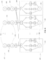
- FIG. 3 another approach to determining x t at each time step is to use a factor graph 300, which is illustrated for the case of a memory polynomial without cross terms.
- the factor graph 300 representing the N th order memory polynomial described above can be implemented by the predistorter 204 of FIG. 2 .
- the current desired output value, w t 310 and a number of past desired output values, w t- 1 ...w t-T 312 are known and illustrated in a top row 314 of variable nodes.
- Each variable node associated with a past desired output value, w t -1 ... w t-T 312 is coupled to a corresponding past estimated output variable, y t -1 ... y t-T 316 through an equal node 318.
- the current desired output variable, w t 310 is coupled to the predicted output ⁇ t 320 through an equal node 322.
- a pre-distorted input value, x t 324 and a number of past pre-distorted input values, x t -1 ... x t-T 326 are illustrated in the bottom row 328 of variable nodes.
- the past pre-distorted input values 326 are known and the current pre-distorted input value 324 is the value that is computed and output as the result of the factor graph 300.
- the factor graph 300 can be seen as including a number of sections 330, 331, ...,333, each related to the desired inputs and predicted outputs at a given time step.
- each section 330, 331,...,333 includes a number of function nodes and variable nodes for calculating a j , k
- portion 330 the portion 330 of the factor graph 300 effectively represents F ⁇ identified above.
- This section 330 has a functional from which remains fixed as long as the parameters, ⁇ , remain fixed.
- this fixed section 330 of the factor graph 300 is replaced with a lookup table which is updated each time the parameters are updated.
- x t 324 In operation, to calculate the output value, x t 324, messages are passed between nodes in the graph, where each message represents a summary of the information known by that node through its connections to other nodes. Eventually, the factor graph converges to a value of x t .
- the resulting value of x t is a pre-distorted value which, when passed to the non-linear element (e.g., FIG. 2 , element 204), causes the non-linear element to output a value ⁇ t which closely matches the desired value w t .
- factor graph shown in FIG. 3 is one example, which is relatively simple. Other forms of factor graph may include different model structures.
- parameters of the model, shown in FIG. 3 as parameters (e.g., a i,j ) of function nodes may themselves be variables in a graph, for example, in a Bayesian framework.
- parameters variable may link a portion of a factor graph that constrains (estimates) the parameters based on past observations of ( x t , y t ) pairs.
- estimation may be performed at a slower timescale, for example, updating the parameters relatively infrequently and/or with a time delay that is substantial compared to the sample time for the signal.
- the power amplifier linearization systems described above include two subsystems.
- the first subsystem implements a slower adaptation algorithm which takes blocks of driving values, x t ,..., x t + ⁇ and y t ,..., y t + ⁇ as inputs and uses them to estimate an updated set of parameters, ⁇ .
- the updated set of parameters are used to configure a predistorter (e.g., FIG. 2 , element 204) which operates in a faster transmit subsystem.
- a predistorter e.g., FIG. 2 , element 204
- One reason for using such a configuration is that estimating the updated parameters can be a computationally intensive and time consuming task which can not feasibly be accomplished in the transmit path. Updating the parameters at a slower rate allows for the transmit path to operate at a high rate while still having an updated set of parameters for the predistorter.
- ⁇ may be estimated using various approaches.
- sparse sampling and/or cross validation techniques may be used.
- the number of number of non-zero parameter values can be limited such that overfitting of the memory polynomial does not occur.
- the parameters are adapted using algorithms such as LMS or RLS.
- the estimate is performed periodically in a batch process, for example, collecting data for a time interval, computing ⁇ , and then operating the predistorter with those parameters. While operating with one set (vector) of parameters, in parallel new data may be collected for computing updated parameters.
- a regularizing prior could for instance be a Gaussian prior with standard deviation ⁇ , which corresponds in the regression over ⁇ to an additional L2 cost ⁇ ⁇ i 2 with multiplicative coefficient 1/ ⁇ 2 .
- the optimal ⁇ one can compute the regression for a family of ⁇ 's, and use cross-validation to determine which sigma corresponded to the best generalization error (error computed on data not used in the training set).
- ⁇ k 0 N a j , k
- k is replaced with a linear combination of orthogonal polynomials (e.g., Laguerre polynomials, Hermite polynomials, Chebyshev polynomials, etc).
- orthogonal polynomials e.g., Laguerre polynomials, Hermite polynomials, Chebyshev polynomials, etc.
- Another approach to regression makes use of frequency weighting, whose aim is to increase the quality of the model.
- filter each component of the feature vector ⁇ t and filter the output vector y t , and do the regression on those filtered components instead.
- the effect of doing so is that if the filter is weighted towards particular frequency bands, the model quality will increase on those corresponding bands. Note that this is not the same as traditional data filtering - we are not filtering data so that it has a particular frequency response; we are filtering the data that goes into the regression model so that the model decreases its error in particular frequency bands, for example, in sidelobe frequency bands.
- a linear filter is designed (FIR or IIR) with a frequency response that amplifies the critical bands and attenuates the non-critical bands.
- the feature vectors in ⁇ t are passed through this filter to give a new weighted feature vector ⁇ t ′ .
- the output y t is also passed through the same filter to give a weighted output ⁇ y ' t . Regression proceeds on ⁇ t ′ and y ' t instead of ⁇ t and y t .
- ⁇ ( ⁇ ' T ⁇ ' ) - 1 ⁇ " T y.
- ⁇ ( ⁇ ' T ⁇ ' ) - 1 ⁇ " T y.
- Another issue that can arise due to repeated estimation of ⁇ is that even if the model does not overfit the data for the sampling window used for the estimation, the sampling window may not provide a sufficient richness of data over a range input conditions such that it the input characteristics change, the model may in fact extrapolate poorly, and potentially match worse than a simple linear model.
- An example of such a scenario can occur when the training data represents a relatively low power level, and the estimated model parameters match that low power operating condition well. However, if the power level increases, for example, to a degree that provokes non-linear characteristics, the model may essentially be extrapolating poorly.
- One approach is to synthesize a training set for parameter estimation by merging data from a high-power situation, which may have been recorded in relatively old time interval, with actual samples in a relatively recent time interval. This combination yields good linearization in the operating condition in the recent time interval, as well as good linearization in an operating condition represented by the older high-power time interval. Furthermore, power levels in between are essentially interpolated, thereby improving over the extrapolation had the high-power data not been included.
- training data sets may be used. For example, multiple older training intervals may be used to sample a range of operating conditions.
- stored training data may be selected according to matches of operating conditions, such as temperature.
- stored training data may be segregated by frequency (e.g., channel) in order to provide diversity in the training data across different frequencies even when the most recent training interval may represent data that is concentrated or limited to particular frequencies.
- a third aspect relates to estimation of the model parameters.
- the estimation can be expressed as being based on a set of data pairs ( y t , ⁇ ( t )) where ⁇ ( t ) includes all the non-linear terms (i.e., including all the cross-terms) that are used in the model.
- a goal is to provide a mapping that is valid for all t from ⁇ ( t ) to y t .
- ⁇ ( t ) does not depend on actual outputs y t- ⁇ , but rather only on computed x t- ⁇ and/or ⁇ t- ⁇ .
- ⁇ ( t 1) ⁇ ( t 2), .. ⁇ ( tn ) for well separated times t 1, t 2 .. tn .
- y t 1 y t 1 , y t 2 , y tn .
- the measured output y t is not required at successive time samples.
- the output of the non-linear element is downsampled (e.g., regularly downsampled at a fixed downsampling factor, or optionally irregularly), and corresponding vectors ⁇ ( t ) at those times are also recorded, thereby enabling estimation based on the paired recorded data.
- the delayed values x t- ⁇ and/or ⁇ t- ⁇ are recorded. However, because of the form of the model, these quantities are required for successive time values.
- some degree of subsampling is used for the input and model outputs, and interpolation is used to compute approximations of the terms needed for estimation of the parameters.
- ⁇ ( t ) does include 'bursts' of sampled y t at successive times
- One approach is to add to sparse sampling is to use a sparse-sampling compatible model to reconstruct the missing values ⁇ t . This can be called "model-based interpolation", since we are using a model of the PA, as well as related data x or w , to properly interpolate and reconstruct the missing values y. Once those y are reconstructed, we compute feature vectors ⁇ and perform the desired regression.
- Software can include instructions stored on a tangible computer readable medium for causing a processor to perform functions described above.
- the processor may be a digital signal processor, a general purpose processor, a numerical accelerator etc.
- Factor graph elements may be implemented in hardware, for instance in fixed implementations, or using a programmable "probability processing" hardware.
- the hardware can also include signal processing elements that have controllable elements, for example, using discrete-time analog signal processing elements.
Landscapes
- Physics & Mathematics (AREA)
- Nonlinear Science (AREA)
- Engineering & Computer Science (AREA)
- Power Engineering (AREA)
- Algebra (AREA)
- General Physics & Mathematics (AREA)
- Mathematical Analysis (AREA)
- Mathematical Optimization (AREA)
- Pure & Applied Mathematics (AREA)
- Amplifiers (AREA)
Claims (17)
- Procédé de linéarisation d'un dispositif non linéaire (102), comprenant les étapes suivantes :- réception des données qui représentent des entrées prédistordues passées (xt-T...xt-1) du dispositif non linaire (102) et des sorties passées correspondantes (yt-T...yt-1) du dispositif non linéaire (102) ;- application d'une procédure d'estimation de paramètres de modèle en utilisant les données reçues afin de générer des paramètres de modèle (Φ) d'un modèle (208) qui caractérise des caractéristiques d'entrée-sortie du dispositif non linéaire (102) ;- réception d'un signal d'entrée (wt) qui représente un signal de sortie souhaité du dispositif non linéaire (102) ;- génération d'un signal d'entrée prédistordu (xt), pour chacune d'une série d'estimations d'échantillons successifs de signal d'entrée prédistordu (x(k)), en appliquant une procédure itérative afin de régler le signal d'entrée prédistordu (xt) à une valeur qui donne une sortie de modèle prédite (ŷt) qui coïncide le mieux avec la sortie souhaitée (wt), sur la base des paramètres de modèle (Φ), desdites entrées prédistordues passées (xt-T...xt-1) et de sorties de modèle prédites non linéaires passées correspondantes (ŷt-T...ŷt-1) ; et- génération du signal d'entrée prédistordu (xt) pour l'appliquer à l'entrée du dispositif non linéaire (102), afin d'amener le dispositif non linéaire (102) à générer une valeur (yt) qui coïncide étroitement avec le signal (wt) qui représente le signal de sortie souhaité.
- Procédé selon la revendication 1, dans lequel le dispositif non linéaire (102) comprend un amplificateur de puissance.
- Procédé selon la revendication 1, dans lequel l'application de la procédure d'estimation de paramètres de modèle comprend l'application d'une approche de régression incomplète, comprenant la sélection d'un sous-ensemble de de paramètres de modèle disponibles pour caractériser des caractéristiques d'entrée-sortie du modèle.
- Procédé selon la revendication 1, dans lequel l'application de la procédure itérative comprend l'application d'une procédure numérique pour résoudre une équation polynomiale.
- Procédé selon la revendication 1, dans lequel l'application de la procédure itérative comprend l'application d'une procédure de propagation de croyance.
- Procédé selon la revendication 1, dans lequel l'application de la procédure itérative pour générer l'échantillon du signal d'entrée modifié comprend la détermination d'une grandeur de l'échantillon et d'une phase de l'échantillon.
- Procédé selon la revendication 1, dans lequel le modèle qui caractérise des caractéristiques d'entrée-sortie du dispositif non linéaire (102) comprend un polynomial de mémoire ou un modèle de la série Volterra.
- Procédé selon la revendication 1, comprenant en outre une interpolation pour trouver des sorties passées manquantes et l'utilisation des sorties passées interpolées dans la procédure d'estimation de paramètres de modèle.
- Procédé selon la revendication 1, dans lequel le modèle qui caractérise des caractéristiques d'entrée-sortie du dispositif non linéaire (102) comprend un modèle qui prédit une sortie du dispositif non linéaire (102) sur la base de données qui représentent un ensemble d'entrées passées et un ensemble de sorties passées du dispositif.
- Procédé selon la revendication 9, dans lequel le modèle qui caractérise des caractéristiques d'entrée-sortie du dispositif non linéaire (102) comprend un modèle de Réponse Impulsionnelle Infinie (IIR).
- Procédé selon l'une quelconque des revendications précédentes, dans lequel les sorties passées (yt-T...yt-1) du dispositif non linéaire (102) sont générées par un sous-échantillonnage irrégulier à un facteur de sous-échantillonnage variable.
- Système de linéarisation d'un dispositif non linéaire (102), le système comprenant :- un estimateur (206) configuré de manière à recevoir des données qui représentent des échantillons passés d'entrées prédistordues (xt-T...xt-1) du dispositif non linaire (102) et de sorties passées correspondantes (yt-T...yt-1) du dispositif non linéaire (102) et à appliquer une procédure d'estimation de paramètres de modèle afin de générer des paramètres de modèle (Φ) d'un modèle (208) qui caractérise des caractéristiques d'entrée-sortie du dispositif non linéaire (102), et l'estimateur (206) est configuré de manière à utiliser les données qui représentent les échantillons passés d'entrées prédistordues (xt-T...xt-1) du dispositif non linaire (102) et de sorties passées correspondantes (yt-T...yt-1) du dispositif non linéaire (102) dans la procédure d'estimation de paramètres de modèle afin de générer les paramètres de modèle (Φ) ; et- un dispositif de prédistorsion (204), comprenant :• une entrée configurée de manière à recevoir un signal d'entrée (wt) qui représente un signal de sortie souhaité du dispositif non linéaire (102) ;• une entrée configurée de manière à recevoir les paramètres de modèle (Φ) en provenance de l'estimateur (206),• une entrée configurée de manière à recevoir les sorties prédites (ŷt-T...ŷt-1) en provenance du modèle (208),• un dispositif de traitement configuré de manière à générer un signal d'entrée prédistordu (xt), pour chacune d'une série d'estimations d'échantillons successifs de signaux d'entrée prédistordus, en appliquant une procédure itérative afin de régler le signal d'entrée prédistordu (xt) à une valeur qui donne une sortie de modèle prédite (ŷt) qui coïncide le mieux avec la sortie souhaitée (wt), sur la base des paramètres de modèle (Φ), desdites entrées prédistordues passées (xt-T...xt-1) et de sorties de modèle prédites non linéaires passées correspondantes (ŷt-T...ŷt-1) ; et• une sortie pour générer le signal d'entrée prédistordu (xt) pour l'appliquer à l'entrée du dispositif non linéaire dans le but de linéariser une sortie du dispositif non linéaire (102), afin d'amener le dispositif non linéaire (102) à générer une valeur (yt) qui coïncide étroitement avec le signal (wt) qui représente le signal de sortie souhaité.
- Système selon la revendication 12, dans lequel l'estimateur (206) est configuré de manière à appliquer une approche de régression incomplète qui comprend la sélection d'un sous-ensemble de paramètres de modèle disponibles afin de caractériser des caractéristiques d'entrée-sortie du modèle (208).
- Système selon la revendication 12, dans lequel le dispositif de traitement est configuré de manière à appliquer une procédure numérique pour résoudre une équation polynomiale ou une procédure de propagation de croyance.
- Système selon la revendication 12, dans lequel le modèle qui caractérise des caractéristiques d'entrée-sortie du dispositif non linéaire comprend un modèle qui prédit une sortie du dispositif non linéaire sur la base de données qui représentent un ensemble d'entrées passées et un ensemble de sorties passées du dispositif.
- Système selon l'une quelconque des revendications 12 à 15, dans lequel les sorties passées (yt-T...yt-1) du dispositif non linéaire (102) sont générées par un sous- échantillonnage irrégulier à un facteur de sous-échantillonnage variable.
- Support lisible par ordinateur non transitoire contenant des instructions pour amener un processeur de données à exécuter des étapes de procédé définies dans l'une quelconque des revendications 1 à 11.
Applications Claiming Priority (4)
| Application Number | Priority Date | Filing Date | Title |
|---|---|---|---|
| US201161560889P | 2011-11-17 | 2011-11-17 | |
| US201261703895P | 2012-09-21 | 2012-09-21 | |
| PCT/US2012/065459 WO2013074890A1 (fr) | 2011-11-17 | 2012-11-16 | Linéarisation de système |
| EP12798973.9A EP2781018A1 (fr) | 2011-11-17 | 2012-11-16 | Linéarisation de système |
Related Parent Applications (1)
| Application Number | Title | Priority Date | Filing Date |
|---|---|---|---|
| EP12798973.9A Division EP2781018A1 (fr) | 2011-11-17 | 2012-11-16 | Linéarisation de système |
Publications (2)
| Publication Number | Publication Date |
|---|---|
| EP3054590A1 EP3054590A1 (fr) | 2016-08-10 |
| EP3054590B1 true EP3054590B1 (fr) | 2019-03-20 |
Family
ID=47326370
Family Applications (2)
| Application Number | Title | Priority Date | Filing Date |
|---|---|---|---|
| EP16150791.8A Active EP3054590B1 (fr) | 2011-11-17 | 2012-11-16 | Linéarisation de système |
| EP12798973.9A Withdrawn EP2781018A1 (fr) | 2011-11-17 | 2012-11-16 | Linéarisation de système |
Family Applications After (1)
| Application Number | Title | Priority Date | Filing Date |
|---|---|---|---|
| EP12798973.9A Withdrawn EP2781018A1 (fr) | 2011-11-17 | 2012-11-16 | Linéarisation de système |
Country Status (6)
| Country | Link |
|---|---|
| US (1) | US20130166259A1 (fr) |
| EP (2) | EP3054590B1 (fr) |
| KR (1) | KR20140096126A (fr) |
| CN (1) | CN103947106B (fr) |
| TW (1) | TW201328172A (fr) |
| WO (1) | WO2013074890A1 (fr) |
Families Citing this family (59)
| Publication number | Priority date | Publication date | Assignee | Title |
|---|---|---|---|---|
| US10230419B2 (en) | 2011-02-03 | 2019-03-12 | The Board Of Trustees Of The Leland Stanford Junior University | Adaptive techniques for full duplex communications |
| US10284356B2 (en) | 2011-02-03 | 2019-05-07 | The Board Of Trustees Of The Leland Stanford Junior University | Self-interference cancellation |
| US10243719B2 (en) | 2011-11-09 | 2019-03-26 | The Board Of Trustees Of The Leland Stanford Junior University | Self-interference cancellation for MIMO radios |
| US9325432B2 (en) | 2012-02-08 | 2016-04-26 | The Board Of Trustees Of The Leland Stanford Junior University | Systems and methods for full-duplex signal shaping |
| TWI503687B (zh) * | 2013-08-08 | 2015-10-11 | Univ Asia | 適應性線性時變濾波方法 |
| WO2015021463A2 (fr) | 2013-08-09 | 2015-02-12 | Kumu Networks, Inc. | Systèmes et procédés d'élimination d'auto-brouillage analogique indépendante de la fréquence |
| US9698860B2 (en) | 2013-08-09 | 2017-07-04 | Kumu Networks, Inc. | Systems and methods for self-interference canceller tuning |
| US11163050B2 (en) | 2013-08-09 | 2021-11-02 | The Board Of Trustees Of The Leland Stanford Junior University | Backscatter estimation using progressive self interference cancellation |
| WO2015021461A1 (fr) * | 2013-08-09 | 2015-02-12 | Kumu Networks, Inc. | Systèmes et procédés d'annulation d'autobrouillage numérique non linéaire |
| US9054795B2 (en) | 2013-08-14 | 2015-06-09 | Kumu Networks, Inc. | Systems and methods for phase noise mitigation |
| CN105493416A (zh) | 2013-08-29 | 2016-04-13 | 库姆网络公司 | 全双工中继装置 |
| US10673519B2 (en) | 2013-08-29 | 2020-06-02 | Kuma Networks, Inc. | Optically enhanced self-interference cancellation |
| US9520983B2 (en) | 2013-09-11 | 2016-12-13 | Kumu Networks, Inc. | Systems for delay-matched analog self-interference cancellation |
| US10230422B2 (en) | 2013-12-12 | 2019-03-12 | Kumu Networks, Inc. | Systems and methods for modified frequency-isolation self-interference cancellation |
| WO2015089460A1 (fr) | 2013-12-12 | 2015-06-18 | Kumu Networks, Inc. | Systèmes et procédés d'annulation d'autobrouillage hybride |
| US9774405B2 (en) | 2013-12-12 | 2017-09-26 | Kumu Networks, Inc. | Systems and methods for frequency-isolated self-interference cancellation |
| US9712312B2 (en) | 2014-03-26 | 2017-07-18 | Kumu Networks, Inc. | Systems and methods for near band interference cancellation |
| WO2015168700A1 (fr) | 2014-05-02 | 2015-11-05 | The Board Of Trustees Of The Leland Stanford Junior University | Procédé et appareil à des fins de suivi de mouvement au moyen de signaux radioélectriques |
| WO2015179874A1 (fr) | 2014-05-23 | 2015-11-26 | Kumu Networks, Inc. | Systèmes et procédés d'annulation d'autobrouillage numérique multi-débit |
| US9521023B2 (en) | 2014-10-17 | 2016-12-13 | Kumu Networks, Inc. | Systems for analog phase shifting |
| US9712313B2 (en) | 2014-11-03 | 2017-07-18 | Kumu Networks, Inc. | Systems for multi-peak-filter-based analog self-interference cancellation |
| US9923658B2 (en) | 2014-12-23 | 2018-03-20 | Intel Corporation | Interference cancelation |
| US9641206B2 (en) | 2015-01-14 | 2017-05-02 | Analog Devices Global | Highly integrated radio frequency transceiver |
| US9673854B2 (en) | 2015-01-29 | 2017-06-06 | Kumu Networks, Inc. | Method for pilot signal based self-inteference cancellation tuning |
| US9667292B2 (en) * | 2015-06-26 | 2017-05-30 | Intel Corporation | Method of processing signals, data processing system, and transceiver device |
| US10474775B2 (en) | 2015-08-31 | 2019-11-12 | Keysight Technologies, Inc. | Method and system for modeling an electronic device under test (DUT) using a kernel method |
| CN106533998B (zh) * | 2015-09-15 | 2020-03-06 | 富士通株式会社 | 非线性特性的确定方法、装置和系统 |
| EP3166223B1 (fr) | 2015-10-13 | 2020-09-02 | Analog Devices Global Unlimited Company | Pre-distorsion numerique de bande ultra-large |
| US9634823B1 (en) | 2015-10-13 | 2017-04-25 | Kumu Networks, Inc. | Systems for integrated self-interference cancellation |
| US10666305B2 (en) | 2015-12-16 | 2020-05-26 | Kumu Networks, Inc. | Systems and methods for linearized-mixer out-of-band interference mitigation |
| US9742593B2 (en) | 2015-12-16 | 2017-08-22 | Kumu Networks, Inc. | Systems and methods for adaptively-tuned digital self-interference cancellation |
| US9800275B2 (en) | 2015-12-16 | 2017-10-24 | Kumu Networks, Inc. | Systems and methods for out-of band-interference mitigation |
| KR102075284B1 (ko) | 2015-12-16 | 2020-02-07 | 쿠무 네트웍스, 아이엔씨. | 시간 지연 필터 |
| US10454444B2 (en) | 2016-04-25 | 2019-10-22 | Kumu Networks, Inc. | Integrated delay modules |
| WO2017189592A1 (fr) | 2016-04-25 | 2017-11-02 | Kumu Networks, Inc. | Modules à retard intégrés |
| US9906428B2 (en) * | 2016-04-28 | 2018-02-27 | Samsung Electronics Co., Ltd. | System and method for frequency-domain weighted least squares |
| US10224970B2 (en) | 2016-05-19 | 2019-03-05 | Analog Devices Global | Wideband digital predistortion |
| US10033413B2 (en) * | 2016-05-19 | 2018-07-24 | Analog Devices Global | Mixed-mode digital predistortion |
| KR101902943B1 (ko) * | 2016-05-23 | 2018-10-02 | 주식회사 케이엠더블유 | 디지털 전치왜곡 장치를 위한 샘플 유효성 판별 방법 및 장치 |
| US10338205B2 (en) | 2016-08-12 | 2019-07-02 | The Board Of Trustees Of The Leland Stanford Junior University | Backscatter communication among commodity WiFi radios |
| CN110100464A (zh) | 2016-10-25 | 2019-08-06 | 小利兰·斯坦福大学托管委员会 | 反向散射环境ism频带信号 |
| CN108574649B (zh) * | 2017-03-08 | 2021-02-02 | 大唐移动通信设备有限公司 | 一种数字预失真系数的确定方法及装置 |
| US10103774B1 (en) | 2017-03-27 | 2018-10-16 | Kumu Networks, Inc. | Systems and methods for intelligently-tuned digital self-interference cancellation |
| JP2020512770A (ja) | 2017-03-27 | 2020-04-23 | クム ネットワークス, インコーポレイテッドKumu Networks, Inc. | 調整可能な帯域外干渉緩和システムおよび方法 |
| KR102145700B1 (ko) | 2017-03-27 | 2020-08-19 | 쿠무 네트웍스, 아이엔씨. | 향상된 선형성 믹서 |
| EP3410605A1 (fr) | 2017-06-02 | 2018-12-05 | Intel IP Corporation | Dispositif de communication et procédé de communication radio |
| US10200076B1 (en) | 2017-08-01 | 2019-02-05 | Kumu Networks, Inc. | Analog self-interference cancellation systems for CMTS |
| US10425115B2 (en) | 2018-02-27 | 2019-09-24 | Kumu Networks, Inc. | Systems and methods for configurable hybrid self-interference cancellation |
| US10868661B2 (en) | 2019-03-14 | 2020-12-15 | Kumu Networks, Inc. | Systems and methods for efficiently-transformed digital self-interference cancellation |
| US10985951B2 (en) | 2019-03-15 | 2021-04-20 | The Research Foundation for the State University | Integrating Volterra series model and deep neural networks to equalize nonlinear power amplifiers |
| US11355049B2 (en) * | 2019-09-26 | 2022-06-07 | Apple, Inc. | Pixel leakage and internal resistance compensation systems and methods |
| US12003350B1 (en) | 2020-02-29 | 2024-06-04 | Space Exploration Technologies Corp. | Configurable orthogonal frequency division multiplexing (OFDM) signal and transmitter and receiver for user terminal to satellite uplink communications |
| US11283666B1 (en) | 2020-02-29 | 2022-03-22 | Space Exploration Technologies Corp. | Stochastic digital pre-distortion compensation in a wireless communications system |
| US11476808B2 (en) | 2020-08-13 | 2022-10-18 | Analog Devices International Unlimited Company | Multi-component digital predistortion |
| TWI743955B (zh) | 2020-08-20 | 2021-10-21 | 瑞昱半導體股份有限公司 | 具有數位預失真機制的功率放大裝置及方法 |
| CN114186435B (zh) * | 2021-12-20 | 2024-10-08 | 大连理工大学 | 一种基于Volterra级数和极点-留数操作的非线性动力响应预测方法 |
| JP7814805B2 (ja) * | 2022-02-24 | 2026-02-17 | 日本無線株式会社 | 信号処理装置 |
| TWI819917B (zh) * | 2022-12-07 | 2023-10-21 | 緯創資通股份有限公司 | 前置補償方法及其前置補償電路 |
| CN120255325A (zh) * | 2025-06-09 | 2025-07-04 | 上海金科机械制造有限公司 | 加工车间的环境控制设备的控制方法、装置、设备及介质 |
Family Cites Families (18)
| Publication number | Priority date | Publication date | Assignee | Title |
|---|---|---|---|---|
| US6587514B1 (en) * | 1999-07-13 | 2003-07-01 | Pmc-Sierra, Inc. | Digital predistortion methods for wideband amplifiers |
| SE520466C2 (sv) * | 2001-11-12 | 2003-07-15 | Ericsson Telefon Ab L M | Metod och anordning vid en digital linjäriseringskoppling |
| SE520728C2 (sv) * | 2001-11-12 | 2003-08-19 | Ericsson Telefon Ab L M | Förfarande för icke-linjär modellering |
| DE60306619T2 (de) * | 2002-01-18 | 2007-06-28 | Siemens Ag | Verbesserung an oder bezüglich leistungsverstärkern |
| US7269231B2 (en) * | 2002-05-31 | 2007-09-11 | Lucent Technologies Inc. | System and method for predistorting a signal using current and past signal samples |
| US20040258176A1 (en) * | 2003-06-19 | 2004-12-23 | Harris Corporation | Precorrection of nonlinear distortion with memory |
| US7336725B2 (en) * | 2004-03-03 | 2008-02-26 | Powerwave Technologies, Inc. | Digital predistortion system and method for high efficiency transmitters |
| CA2560281A1 (fr) * | 2004-03-25 | 2005-10-13 | Optichron, Inc. | Reduction de distorsion basee sur un modele pour amplificateurs de puissance |
| US20050242876A1 (en) * | 2004-04-28 | 2005-11-03 | Obernosterer Frank G E | Parameter estimation method and apparatus |
| DE102005025676B4 (de) * | 2005-06-03 | 2007-06-28 | Infineon Technologies Ag | Verfahren zum Erzeugen eines Systems für eine Repräsentation eines elektrischen Netzwerks und Verwendung des Verfahrens |
| US7606539B2 (en) * | 2006-08-07 | 2009-10-20 | Infineon Technologies Ag | Adaptive predistorter coupled to a nonlinear element |
| US7561857B2 (en) * | 2006-08-30 | 2009-07-14 | Infineon Technologies Ag | Model network of a nonlinear circuitry |
| US8271223B2 (en) * | 2006-11-22 | 2012-09-18 | Parkervision, Inc. | Multi-dimensional error definition, error measurement, error analysis, error function generation, error information optimization, and error correction for communications systems |
| US7773692B2 (en) * | 2006-12-01 | 2010-08-10 | Texas Instruments Incorporated | System and methods for digitally correcting a non-linear element using a digital filter for predistortion |
| US8005162B2 (en) * | 2007-04-20 | 2011-08-23 | Microelectronics Technology, Inc. | Dynamic digital pre-distortion system |
| EP1998436A1 (fr) * | 2007-05-31 | 2008-12-03 | Nokia Siemens Networks Oy | Procédé et dispositif pour compenser au moins partiellement les effets non-linéaire d'un système et système de communication comportant un tel dispositif |
| WO2010102441A1 (fr) * | 2009-03-09 | 2010-09-16 | Zte Wistron Telecom Ab | Procédé et appareil pour linéariser un amplificateur de puissance non linéaire |
| WO2013007300A1 (fr) * | 2011-07-13 | 2013-01-17 | Nokia Siemens Networks Oy | Pré-distorsion de signal pour amplificateur non linéaire |
-
2012
- 2012-11-16 EP EP16150791.8A patent/EP3054590B1/fr active Active
- 2012-11-16 EP EP12798973.9A patent/EP2781018A1/fr not_active Withdrawn
- 2012-11-16 KR KR1020147016316A patent/KR20140096126A/ko not_active Abandoned
- 2012-11-16 WO PCT/US2012/065459 patent/WO2013074890A1/fr not_active Ceased
- 2012-11-16 US US13/678,904 patent/US20130166259A1/en not_active Abandoned
- 2012-11-16 TW TW101142819A patent/TW201328172A/zh unknown
- 2012-11-16 CN CN201280056330.1A patent/CN103947106B/zh active Active
Non-Patent Citations (1)
| Title |
|---|
| None * |
Also Published As
| Publication number | Publication date |
|---|---|
| EP3054590A1 (fr) | 2016-08-10 |
| CN103947106B (zh) | 2017-08-15 |
| CN103947106A (zh) | 2014-07-23 |
| KR20140096126A (ko) | 2014-08-04 |
| WO2013074890A1 (fr) | 2013-05-23 |
| EP2781018A1 (fr) | 2014-09-24 |
| US20130166259A1 (en) | 2013-06-27 |
| TW201328172A (zh) | 2013-07-01 |
Similar Documents
| Publication | Publication Date | Title |
|---|---|---|
| EP3054590B1 (fr) | Linéarisation de système | |
| US10523159B2 (en) | Digital compensator for a non-linear system | |
| US8046199B2 (en) | System and method for computing parameters for a digital predistorter | |
| US7773692B2 (en) | System and methods for digitally correcting a non-linear element using a digital filter for predistortion | |
| US20220007263A1 (en) | Method and system for baseband predistortion linearization in multi-channel wideband communication systems | |
| CN103201949B (zh) | 具有抽头输出归一化的非线性模型 | |
| US7822146B2 (en) | System and method for digitally correcting a non-linear element | |
| US8787494B2 (en) | Modeling digital predistorter | |
| US7729446B2 (en) | System and method for digitally correcting a non-linear element using a multiply partitioned architecture for predistortion | |
| CN100477500C (zh) | 功率放大器预失真器及其包括该预失真器的基站 | |
| US7847631B2 (en) | Method and apparatus for performing predistortion | |
| KR20060026480A (ko) | Rf 전력 증폭기 내에서 메모리 효과들을 정정하는 디지털 전치 왜곡 시스템 및 방법 | |
| WO2012066380A1 (fr) | Système d'estimation de procédé conjoint avec ligne de retard à rapport variable à utiliser dans une prédistorsion numérique d'un amplificateur de puissance | |
| US7412469B2 (en) | Power amplifier pre-distorter training | |
| KR102097521B1 (ko) | 고주파 증폭 장치 및 왜곡보상 방법 | |
| KR20090125597A (ko) | 협대역 신호를 이용한 광대역 신호의 비선형 모델 파라미터추출 방법 및 이를 이용한 전치 왜곡 장치 및 그 방법 | |
| CN119183639A (zh) | 对输入信号进行预失真的方法,以补偿功率放大器的非线性传递函数的影响,及其计算机程序产品和设备 | |
| KR20100016806A (ko) | 확장 메모리 다항식을 이용한 디지털 전치 왜곡 장치 및 그방법 | |
| HK40047878A (en) | Method and system for baseband predistortion linearization in multi-channel wideband communication systems |
Legal Events
| Date | Code | Title | Description |
|---|---|---|---|
| PUAI | Public reference made under article 153(3) epc to a published international application that has entered the european phase |
Free format text: ORIGINAL CODE: 0009012 |
|
| AC | Divisional application: reference to earlier application |
Ref document number: 2781018 Country of ref document: EP Kind code of ref document: P |
|
| AK | Designated contracting states |
Kind code of ref document: A1 Designated state(s): AL AT BE BG CH CY CZ DE DK EE ES FI FR GB GR HR HU IE IS IT LI LT LU LV MC MK MT NL NO PL PT RO RS SE SI SK SM TR |
|
| STAA | Information on the status of an ep patent application or granted ep patent |
Free format text: STATUS: REQUEST FOR EXAMINATION WAS MADE |
|
| STAA | Information on the status of an ep patent application or granted ep patent |
Free format text: STATUS: EXAMINATION IS IN PROGRESS |
|
| 17P | Request for examination filed |
Effective date: 20170208 |
|
| RBV | Designated contracting states (corrected) |
Designated state(s): AL AT BE BG CH CY CZ DE DK EE ES FI FR GB GR HR HU IE IS IT LI LT LU LV MC MK MT NL NO PL PT RO RS SE SI SK SM TR |
|
| 17Q | First examination report despatched |
Effective date: 20170316 |
|
| GRAP | Despatch of communication of intention to grant a patent |
Free format text: ORIGINAL CODE: EPIDOSNIGR1 |
|
| STAA | Information on the status of an ep patent application or granted ep patent |
Free format text: STATUS: GRANT OF PATENT IS INTENDED |
|
| INTG | Intention to grant announced |
Effective date: 20181008 |
|
| GRAS | Grant fee paid |
Free format text: ORIGINAL CODE: EPIDOSNIGR3 |
|
| GRAA | (expected) grant |
Free format text: ORIGINAL CODE: 0009210 |
|
| STAA | Information on the status of an ep patent application or granted ep patent |
Free format text: STATUS: THE PATENT HAS BEEN GRANTED |
|
| AC | Divisional application: reference to earlier application |
Ref document number: 2781018 Country of ref document: EP Kind code of ref document: P |
|
| AK | Designated contracting states |
Kind code of ref document: B1 Designated state(s): AL AT BE BG CH CY CZ DE DK EE ES FI FR GB GR HR HU IE IS IT LI LT LU LV MC MK MT NL NO PL PT RO RS SE SI SK SM TR |
|
| REG | Reference to a national code |
Ref country code: GB Ref legal event code: FG4D |
|
| REG | Reference to a national code |
Ref country code: CH Ref legal event code: EP |
|
| REG | Reference to a national code |
Ref country code: DE Ref legal event code: R096 Ref document number: 602012058167 Country of ref document: DE |
|
| REG | Reference to a national code |
Ref country code: AT Ref legal event code: REF Ref document number: 1111552 Country of ref document: AT Kind code of ref document: T Effective date: 20190415 |
|
| REG | Reference to a national code |
Ref country code: IE Ref legal event code: FG4D |
|
| REG | Reference to a national code |
Ref country code: NL Ref legal event code: MP Effective date: 20190320 |
|
| PG25 | Lapsed in a contracting state [announced via postgrant information from national office to epo] |
Ref country code: SE Free format text: LAPSE BECAUSE OF FAILURE TO SUBMIT A TRANSLATION OF THE DESCRIPTION OR TO PAY THE FEE WITHIN THE PRESCRIBED TIME-LIMIT Effective date: 20190320 Ref country code: LT Free format text: LAPSE BECAUSE OF FAILURE TO SUBMIT A TRANSLATION OF THE DESCRIPTION OR TO PAY THE FEE WITHIN THE PRESCRIBED TIME-LIMIT Effective date: 20190320 Ref country code: NO Free format text: LAPSE BECAUSE OF FAILURE TO SUBMIT A TRANSLATION OF THE DESCRIPTION OR TO PAY THE FEE WITHIN THE PRESCRIBED TIME-LIMIT Effective date: 20190620 Ref country code: FI Free format text: LAPSE BECAUSE OF FAILURE TO SUBMIT A TRANSLATION OF THE DESCRIPTION OR TO PAY THE FEE WITHIN THE PRESCRIBED TIME-LIMIT Effective date: 20190320 |
|
| REG | Reference to a national code |
Ref country code: LT Ref legal event code: MG4D |
|
| PG25 | Lapsed in a contracting state [announced via postgrant information from national office to epo] |
Ref country code: BG Free format text: LAPSE BECAUSE OF FAILURE TO SUBMIT A TRANSLATION OF THE DESCRIPTION OR TO PAY THE FEE WITHIN THE PRESCRIBED TIME-LIMIT Effective date: 20190620 Ref country code: NL Free format text: LAPSE BECAUSE OF FAILURE TO SUBMIT A TRANSLATION OF THE DESCRIPTION OR TO PAY THE FEE WITHIN THE PRESCRIBED TIME-LIMIT Effective date: 20190320 Ref country code: RS Free format text: LAPSE BECAUSE OF FAILURE TO SUBMIT A TRANSLATION OF THE DESCRIPTION OR TO PAY THE FEE WITHIN THE PRESCRIBED TIME-LIMIT Effective date: 20190320 Ref country code: LV Free format text: LAPSE BECAUSE OF FAILURE TO SUBMIT A TRANSLATION OF THE DESCRIPTION OR TO PAY THE FEE WITHIN THE PRESCRIBED TIME-LIMIT Effective date: 20190320 Ref country code: HR Free format text: LAPSE BECAUSE OF FAILURE TO SUBMIT A TRANSLATION OF THE DESCRIPTION OR TO PAY THE FEE WITHIN THE PRESCRIBED TIME-LIMIT Effective date: 20190320 Ref country code: GR Free format text: LAPSE BECAUSE OF FAILURE TO SUBMIT A TRANSLATION OF THE DESCRIPTION OR TO PAY THE FEE WITHIN THE PRESCRIBED TIME-LIMIT Effective date: 20190621 |
|
| REG | Reference to a national code |
Ref country code: AT Ref legal event code: MK05 Ref document number: 1111552 Country of ref document: AT Kind code of ref document: T Effective date: 20190320 |
|
| PG25 | Lapsed in a contracting state [announced via postgrant information from national office to epo] |
Ref country code: SK Free format text: LAPSE BECAUSE OF FAILURE TO SUBMIT A TRANSLATION OF THE DESCRIPTION OR TO PAY THE FEE WITHIN THE PRESCRIBED TIME-LIMIT Effective date: 20190320 Ref country code: PT Free format text: LAPSE BECAUSE OF FAILURE TO SUBMIT A TRANSLATION OF THE DESCRIPTION OR TO PAY THE FEE WITHIN THE PRESCRIBED TIME-LIMIT Effective date: 20190720 Ref country code: AL Free format text: LAPSE BECAUSE OF FAILURE TO SUBMIT A TRANSLATION OF THE DESCRIPTION OR TO PAY THE FEE WITHIN THE PRESCRIBED TIME-LIMIT Effective date: 20190320 Ref country code: EE Free format text: LAPSE BECAUSE OF FAILURE TO SUBMIT A TRANSLATION OF THE DESCRIPTION OR TO PAY THE FEE WITHIN THE PRESCRIBED TIME-LIMIT Effective date: 20190320 Ref country code: RO Free format text: LAPSE BECAUSE OF FAILURE TO SUBMIT A TRANSLATION OF THE DESCRIPTION OR TO PAY THE FEE WITHIN THE PRESCRIBED TIME-LIMIT Effective date: 20190320 Ref country code: ES Free format text: LAPSE BECAUSE OF FAILURE TO SUBMIT A TRANSLATION OF THE DESCRIPTION OR TO PAY THE FEE WITHIN THE PRESCRIBED TIME-LIMIT Effective date: 20190320 Ref country code: CZ Free format text: LAPSE BECAUSE OF FAILURE TO SUBMIT A TRANSLATION OF THE DESCRIPTION OR TO PAY THE FEE WITHIN THE PRESCRIBED TIME-LIMIT Effective date: 20190320 |
|
| PG25 | Lapsed in a contracting state [announced via postgrant information from national office to epo] |
Ref country code: SM Free format text: LAPSE BECAUSE OF FAILURE TO SUBMIT A TRANSLATION OF THE DESCRIPTION OR TO PAY THE FEE WITHIN THE PRESCRIBED TIME-LIMIT Effective date: 20190320 Ref country code: PL Free format text: LAPSE BECAUSE OF FAILURE TO SUBMIT A TRANSLATION OF THE DESCRIPTION OR TO PAY THE FEE WITHIN THE PRESCRIBED TIME-LIMIT Effective date: 20190320 |
|
| PG25 | Lapsed in a contracting state [announced via postgrant information from national office to epo] |
Ref country code: IS Free format text: LAPSE BECAUSE OF FAILURE TO SUBMIT A TRANSLATION OF THE DESCRIPTION OR TO PAY THE FEE WITHIN THE PRESCRIBED TIME-LIMIT Effective date: 20190720 Ref country code: AT Free format text: LAPSE BECAUSE OF FAILURE TO SUBMIT A TRANSLATION OF THE DESCRIPTION OR TO PAY THE FEE WITHIN THE PRESCRIBED TIME-LIMIT Effective date: 20190320 |
|
| REG | Reference to a national code |
Ref country code: DE Ref legal event code: R097 Ref document number: 602012058167 Country of ref document: DE |
|
| PLBE | No opposition filed within time limit |
Free format text: ORIGINAL CODE: 0009261 |
|
| STAA | Information on the status of an ep patent application or granted ep patent |
Free format text: STATUS: NO OPPOSITION FILED WITHIN TIME LIMIT |
|
| PG25 | Lapsed in a contracting state [announced via postgrant information from national office to epo] |
Ref country code: DK Free format text: LAPSE BECAUSE OF FAILURE TO SUBMIT A TRANSLATION OF THE DESCRIPTION OR TO PAY THE FEE WITHIN THE PRESCRIBED TIME-LIMIT Effective date: 20190320 |
|
| 26N | No opposition filed |
Effective date: 20200102 |
|
| PG25 | Lapsed in a contracting state [announced via postgrant information from national office to epo] |
Ref country code: SI Free format text: LAPSE BECAUSE OF FAILURE TO SUBMIT A TRANSLATION OF THE DESCRIPTION OR TO PAY THE FEE WITHIN THE PRESCRIBED TIME-LIMIT Effective date: 20190320 |
|
| PG25 | Lapsed in a contracting state [announced via postgrant information from national office to epo] |
Ref country code: TR Free format text: LAPSE BECAUSE OF FAILURE TO SUBMIT A TRANSLATION OF THE DESCRIPTION OR TO PAY THE FEE WITHIN THE PRESCRIBED TIME-LIMIT Effective date: 20190320 |
|
| REG | Reference to a national code |
Ref country code: CH Ref legal event code: PL |
|
| PG25 | Lapsed in a contracting state [announced via postgrant information from national office to epo] |
Ref country code: LI Free format text: LAPSE BECAUSE OF NON-PAYMENT OF DUE FEES Effective date: 20191130 Ref country code: LU Free format text: LAPSE BECAUSE OF NON-PAYMENT OF DUE FEES Effective date: 20191116 Ref country code: CH Free format text: LAPSE BECAUSE OF NON-PAYMENT OF DUE FEES Effective date: 20191130 Ref country code: MC Free format text: LAPSE BECAUSE OF FAILURE TO SUBMIT A TRANSLATION OF THE DESCRIPTION OR TO PAY THE FEE WITHIN THE PRESCRIBED TIME-LIMIT Effective date: 20190320 |
|
| REG | Reference to a national code |
Ref country code: BE Ref legal event code: MM Effective date: 20191130 |
|
| PG25 | Lapsed in a contracting state [announced via postgrant information from national office to epo] |
Ref country code: IE Free format text: LAPSE BECAUSE OF NON-PAYMENT OF DUE FEES Effective date: 20191116 |
|
| PG25 | Lapsed in a contracting state [announced via postgrant information from national office to epo] |
Ref country code: BE Free format text: LAPSE BECAUSE OF NON-PAYMENT OF DUE FEES Effective date: 20191130 |
|
| PG25 | Lapsed in a contracting state [announced via postgrant information from national office to epo] |
Ref country code: CY Free format text: LAPSE BECAUSE OF FAILURE TO SUBMIT A TRANSLATION OF THE DESCRIPTION OR TO PAY THE FEE WITHIN THE PRESCRIBED TIME-LIMIT Effective date: 20190320 |
|
| PG25 | Lapsed in a contracting state [announced via postgrant information from national office to epo] |
Ref country code: HU Free format text: LAPSE BECAUSE OF FAILURE TO SUBMIT A TRANSLATION OF THE DESCRIPTION OR TO PAY THE FEE WITHIN THE PRESCRIBED TIME-LIMIT; INVALID AB INITIO Effective date: 20121116 Ref country code: MT Free format text: LAPSE BECAUSE OF FAILURE TO SUBMIT A TRANSLATION OF THE DESCRIPTION OR TO PAY THE FEE WITHIN THE PRESCRIBED TIME-LIMIT Effective date: 20190320 |
|
| PGFP | Annual fee paid to national office [announced via postgrant information from national office to epo] |
Ref country code: IT Payment date: 20211025 Year of fee payment: 10 |
|
| PG25 | Lapsed in a contracting state [announced via postgrant information from national office to epo] |
Ref country code: MK Free format text: LAPSE BECAUSE OF FAILURE TO SUBMIT A TRANSLATION OF THE DESCRIPTION OR TO PAY THE FEE WITHIN THE PRESCRIBED TIME-LIMIT Effective date: 20190320 |
|
| PG25 | Lapsed in a contracting state [announced via postgrant information from national office to epo] |
Ref country code: IT Free format text: LAPSE BECAUSE OF NON-PAYMENT OF DUE FEES Effective date: 20221116 |
|
| PGFP | Annual fee paid to national office [announced via postgrant information from national office to epo] |
Ref country code: DE Payment date: 20251022 Year of fee payment: 14 |
|
| PGFP | Annual fee paid to national office [announced via postgrant information from national office to epo] |
Ref country code: GB Payment date: 20251023 Year of fee payment: 14 |
|
| PGFP | Annual fee paid to national office [announced via postgrant information from national office to epo] |
Ref country code: FR Payment date: 20251022 Year of fee payment: 14 |