EP3054825B2 - Appareils de cuisine avec commande de vitesse - Google Patents
Appareils de cuisine avec commande de vitesse Download PDFInfo
- Publication number
- EP3054825B2 EP3054825B2 EP14802884.8A EP14802884A EP3054825B2 EP 3054825 B2 EP3054825 B2 EP 3054825B2 EP 14802884 A EP14802884 A EP 14802884A EP 3054825 B2 EP3054825 B2 EP 3054825B2
- Authority
- EP
- European Patent Office
- Prior art keywords
- button
- appliance
- power switch
- actuator
- moved
- Prior art date
- Legal status (The legal status is an assumption and is not a legal conclusion. Google has not performed a legal analysis and makes no representation as to the accuracy of the status listed.)
- Active
Links
Images

Classifications
-
- A—HUMAN NECESSITIES
- A47—FURNITURE; DOMESTIC ARTICLES OR APPLIANCES; COFFEE MILLS; SPICE MILLS; SUCTION CLEANERS IN GENERAL
- A47J—KITCHEN EQUIPMENT; COFFEE MILLS; SPICE MILLS; APPARATUS FOR MAKING BEVERAGES
- A47J43/00—Implements for preparing or holding food, not provided for in other groups of this subclass
- A47J43/04—Machines for domestic use not covered elsewhere, e.g. for grinding, mixing, stirring, kneading, emulsifying, whipping or beating foodstuffs, e.g. power-driven
- A47J43/07—Parts or details, e.g. mixing tools, whipping tools
- A47J43/08—Driving mechanisms
- A47J43/082—Driving mechanisms for machines with tools driven from the upper side
-
- A—HUMAN NECESSITIES
- A47—FURNITURE; DOMESTIC ARTICLES OR APPLIANCES; COFFEE MILLS; SPICE MILLS; SUCTION CLEANERS IN GENERAL
- A47J—KITCHEN EQUIPMENT; COFFEE MILLS; SPICE MILLS; APPARATUS FOR MAKING BEVERAGES
- A47J43/00—Implements for preparing or holding food, not provided for in other groups of this subclass
- A47J43/04—Machines for domestic use not covered elsewhere, e.g. for grinding, mixing, stirring, kneading, emulsifying, whipping or beating foodstuffs, e.g. power-driven
- A47J43/044—Machines for domestic use not covered elsewhere, e.g. for grinding, mixing, stirring, kneading, emulsifying, whipping or beating foodstuffs, e.g. power-driven with tools driven from the top side
- A47J2043/04409—Apparatus of hand held type
- A47J2043/04427—Apparatus of hand held type with housing extending vertically in line with the tool axis
Definitions
- This invention relates to kitchen appliances having a speed adjustment function.
- One example is bar blenders.
- bar blenders According to regulations it is required to separate power supply circuits and control circuits in kitchen devices. For this reason, current kitchen appliances such as bar blenders have a user interface which provides galvanic separation of power control and speed adjustment. Thus, bar blenders typically have an on-off control switch, and a separate speed control input. There are various ways to implement the user interface to provide an easy to use device.
- a first known approach is to provide a speed pre-selection switch and a separate push type on/off switch, which needs to be held on.
- the speed is pre-selected before the rotation of the tool is activated by pressing the on/off-switch.
- Some devices comprise an additional turbo switch to boost the speed.
- a second known approach is to provide an on/off switch in the form of a switch which can be locked into its on and off positions, and a separate speed regulation switch.
- the speed regulation switch can be pressure sensitive or it can move along a pathway which is related to speed.
- Document FR 2 754 166 A1 discloses a kitchen appliance with speed control. It would be more convenient to provide a combined on/off and speed regulation switch, to give a one-switch solution. This would enable user operation with only one user interface. However, this is inconsistent with the requirement for separate circuits.
- the amount of movement of the input switch for a hand held device such as a bar blender is limited since the whole device is gripped in the palm of the hand. A compact switch arrangement is therefore needed.
- a push switch should have a short path of movement, since long movement paths are associated by customers with low quality, and they also hamper accurate operation of the device.
- a kitchen appliance comprising a push button arrangement and a motor, wherein the push button arrangement is for controlling the on-off actuation of the motor as well as a speed of the motor, and comprises:
- the invention thus provides a kitchen appliance which combines a power on-off function and a speed control function into a single movable button.
- a separate speed control circuit and power switch is provided, but they are both operated by respective actuators carried by the same carrier, which is moved by the button.
- the button can for example be pressed by the user of the appliance, although the button can be arranged to have a sliding or pivoting movement.
- the speed control circuit can comprise a travel sensing circuit, and the second actuator comprises a travel element for controlling the travel sensing circuit.
- the travel sensing circuit can have a resistance, capacitance or inductance which is a function of the amount of travel, and the level of this resistance, capacitance or inductance is then used to control the speed.
- the travel sensing circuit comprises a set of discrete resistors, or a potentiometer circuit
- the second actuator then comprises a contact element for creating an electrical circuit with a desired resistor or set of resistors, or a desired potentiometer setting.
- the first actuator can comprise a spring-loaded pin carried by the carrier, beneath the button, for mechanically engaging with the power switch when the button is first moved.
- the spring loading enables the pin to retract after it has engaged the power switch, but maintaining the power switch actuation.
- the power switch can comprise a micro switch with a push contact which is pushed by the first actuator to close the switch. This provides a compact arrangement. Furthermore, the reliability of the switch contact is achieved by suitable selection of micro switch.
- the power switch can comprise a pair of electrical contacts which are shorted by the first actuator when the button is first moved. This provides an even simpler arrangement of the power switch.
- the power switch can comprise a pair of electrical contacts which are shorted by a shorting member, wherein the shorting member is biased into a non-shorting position, and the shorting member is moved into contact with the pair of electrical contacts when the button is first moved, wherein the shorting member is biased into a non-shorting position and is moved into the shorting position by movement of the carrier.
- This arrangement also provides simple shorting of contacts.
- a return spring is preferably provided for biasing the carrier to an initial button position. This is arranged to return the button to a position in which the power switch is open, and the first actuator is released from the power switch.
- the return spring can comprise a coil spring, although other biasing arrangements can be used.
- the speed control circuit is additionally controlled to provide a step increase in speed when the button is moved into its final position.
- This function is often called a turbo or boost function, and it provides a maximum speed setting, a step higher than the maximum speed at the end of the range of variable speed control.
- the appliance can further comprise a tactile, audible or visual feedback system for providing feedback during button movement. This gives the user greater control of the speed.
- the power switch is mechanically actuated within 3mm of movement of the button from An initial button position, and more preferably within 2mm of movement of the button from the initial position. This provides a short movement distance before the speed adjustment function is enabled.
- the movement of the button can be limited to at most 20mm, more preferably at most 10mm. This means the full control is achieved within a short range of movement, which is found to provide an interface which is easiest and most comfortable for the user.
- the appliance can comprise one of:
- Some of these may be hand held devices and others may be table top mounted. In all cases, a power on-off function is needed as well as a speed control, and the invention provides a single control button for implementing both functions.
- the invention is for example of particular interest for bar blenders, which comprise a main housing having a handle grip portion and a motor within the housing for driving a blender blade.
- the power switch is for controlling the supply of power to the motor, and the button is located at the handle grip portion.
- the invention provides a kitchen appliance having a power switch for controlling supply of power to a motor and a separate control circuit for controlling the speed.
- a button for control by the user is provided for controlling the actuation and speed.
- a carrier carries the button, and also carries a first actuator for mechanically actuating the power switch when the button is first moved. When the button is further moved, the motor speed is controlled.
- This provides a one-button solution, combining the power on/off function and the speed adjustment in one switch, and which can be designed with a minimum length of travel of the button.
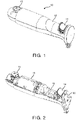
- Figure 1 shows a first example of bar blender using the switch arrangement of the invention, in perspective view.
- the blender comprises a main housing 10 having a handle grip portion 12.
- a user control switch is at the handle grip portion for controlling the motor actuation and speed.
- the user control switch comprises a push button 14, positioned at the location of the user's index finger when gripping the handle.
- a release button 15 enables fitted attachments such as a blending tool or whisking tool to be swapped over.
- Figure 2 shows the bar blender with a top cover removed to show the arrangement of internal components.
- the blender has a motor 16 within the main housing for driving a blender blade or other attachments.
- control circuit for the blender including circuitry mounted on a PCB 18 for controlling the motor speed.
- this circuitry includes a resistor circuit for providing an adjustable motor drive.
- This resistor circuit can comprise a chain of resistors connected in series, which results in a step type control.
- a slider is in contact with the resistors, and the movement of the slider results in selection of one of the resistors. This provides a discrete control approach.
- a directly analogous alternative is to use an analogue potentiometer.
- the push button 14 is mounted within a housing 20 which enables the push button 14 to slide relative to the housing.
- the push button 14 is carried by a carrier (although it should be understood that the carrier and push button can be a single integrated component).
- the push button 14 and its carrier form part of what is termed in this document a "push button arrangement".
- the push button can be considered to be the external feature which the user presses, and the carrier is the structure beneath.
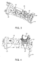
- FIG. 3 shows in more detail the housing 20 which carries the push button arrangement (and shows the push button removed).
- the housing forms a cradle for the push button and its carrier.
- a micro switch 22 functioning as a power switch. This is a switch which is actuated by very little physical force, typically through the use of a tipping point mechanism (otherwise known as an "over-center” mechanism). Switching takes place at specific and repeatable positions of the actuator and with a small amount of movement required between the different switch positions.
- the mains input cable 24 is electrically connected to the rest of the device through the power switch 22, so that the power switch 22 controls the supply of power to the remainder of the device, and thus functions (at least) as the power supply control for the motor.
- the mains cable 24 is to one side of the housing 20 (at the top end of the main housing), and the other side of the housing has a slot 26.
- the push button arrangement includes an electrical contact which slides up and down the slot 26 when the push button is moved. This electrical contact interfaces with electrical contact tracks on the PCB 18, which connect to the discrete resistors mentioned above. For this purpose, an edge of the PCB 18 is aligned with the slot 26 as shown.
- the motor is not shown in Figure 3 , but a motor support which fixes to the motor is shown as 28.
- Figure 4 shows in more detail the push button arrangement mounted in its housing 20.
- the push button arrangement has retaining hooks 29 which clip the push button arrangement into the housing 20 thereby limiting the upward movement of the button.
- the downward movement is limited by a mechanical stop arrangement, which is engaged when the push button is fully depressed.
- Figure 5 shows a cross sectional view of the push button arrangement and its housing and shows the on/off function more clearly.
- the push button 14 and its slidable carrier 40 can be seen more clearly.
- a base 42 of the carrier together with a corresponding part of the housing 20 define the mechanical stop mentioned above which limits the pressing-in of the button 14.
- the micro switch 22 At the base of the housing is located the micro switch (power switch) 22.
- a spring loaded pin 44 is carried by the slidable carrier 40, beneath the button 14, for mechanically engaging with the power switch when the button is first depressed. This spring loaded pin functions as a first actuator for mechanically actuating the power switch when the button is first depressed.
- the spring 45 of the spring loaded pin is located centrally inside the pin (which is hollow for this purpose) and biases the pin towards the power switch. The spring force is sufficient to activate the switch.
- the carrier 40 is biased into the non-depressed position by a return spring 46.
- this is arranged concentrically outside the spring 45 of the pin 44, to provide a compact arrangement.
- the spring loaded pin 44 is biased outwardly by the spring 45 and reaches a stop which means that it is just above the power switch when the carrier 40 is in the non-depressed position. There is a clearance of around 1mm as explained below.
- the pin 44 can retract and a sliding sleeve arrangement enables this.
- Figure 5 also shows more clearly the resistor circuit PCB contacts 50 and the contact element 52 carried by the carrier 40.
- the edge of the PCB 18 sits in the space between the two contacts 52. The relative position of the contacts 52 along the PCB edge determines which PCB tracks are electrically connected, which then determines the setting of the speed control circuit.
- FIG. 6 shows the speed control function of the push button more clearly.
- the PCB 18 has resistor tracks 50, and sliding contacts 52 are mounted to move with the carrier 40 and engage with the PCB tracks.
- the sliding contacts (of which there may be one or more) control the coupling of resistors. In this way, a circuit resistance is controlled in dependence on the push button position. This is then used in a motor control circuit, for example a transistor circuit with variable load depending on the resistor setting.
- the sliding contacts function as a second actuator for controlling the motor speed when the button is further depressed.
- This design makes use of a micro switch for the power on/off function.
- Speed setting resistors are connected by lead tracks on the PCB. This arrangement enables a minimum push button path length. The micro switch power switch is activated first, and the speed is regulated according to the subsequent path of the push button.
- the device After the power switch is activated, at first the device will not rotate. After a travelling distance of 2mm for example, the device starts rotating with speed setting 1. For an additional travelling distance of for example 1 mm, the speed remains at speed 1. After a total travelling distance of 3mm the slider 52 then switches to the next resistor and the speed is set to speed setting 2. The progressive movement of the carrier thus causes the speed control circuit to steps through the speed settings.
- the resistor tracks can be designed to provide a speed according to an arithmetic function in relation to the depression of the push button.
- the function could be linear, exponential, cascading or any other suitable function.
- a turbo boost function is implemented by the single switch, at the maximum movement (maximum depression) of the push button position.
- the turbo boost function provides a step increase in speed when the button is fully moved (fully depressed).
- the speed control enables selection of a speed from a set of speeds in a first range, or selection of a speed which is larger than the highest speed in the first range, and also a larger increase in speed compared to the difference in speed between any adjacent speeds in the first range.
- the switch slides along a predefined path of approximately 1mm until the spring loaded pin contacts the micro-switch. This initial 1mm clearance provides a safety measure to ensure that the return spring does indeed disengage the power switch.
- the pin is preloaded with a spring-force to be able to immediately activate the micro-switch, which has a switching path of approximately 1 mm.
- the spring force of the spring loaded pin can be higher than the spring force of the return spring.
- the total path is approximately 2mm which is a desirable value based on bar-blender consumer application tests.
- this path length is less than 3mm, and it may be 2mm or less.
- the motor and its attached tool begin to rotate slowly.
- the user can further move the push button along its pathway for up to 8mm to adjust the required speed.
- the pin depresses 44 into the carrier 40 against the spring 45.
- the carrier meets mechanical stops.
- a turbo boost function is provided, which is enabled only when the button is in this mechanically stopped fully depressed position.
- the switch When the user releases the button, the switch is returned to the starting position and is disconnected from the power source by deactivation of the micro-switch.
- the total path length can in this example be kept to 10mm or less. It is generally preferred that this path length is less than 20mm.
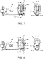
- the example above makes use of a micro switch for the power switch.
- Figure 7 shows a first alternative implementation of the power switch, and shows cross sections taken at two perpendicular angles.
- the same reference numbers are used as in the first example for the same components.
- the switch again has a spring loaded pin 44 (the spring is not shown in Figure 7 ), but in this arrangement, the pin is for providing a short by directly contacting two spaced apart contact electrodes 70,72 at the base of the housing. This can provide an even more compact arrangement with fewer components.
- the spring force of the spring loaded pin is designed to ensure that reliable electrical contact is maintained.
- Figure 8 shows a second alternative implementation of the power switch.
- a pair of electrical contacts 80, 82 is provided laterally near the base of the housing.
- a shorting member 84 is mounted within the housing for shorting the contacts.
- the shorting member 84 is biased into a non-shorting position (as shown in Figure 8 ) by a spring steel configuration 86, and the shorting member is moved into contact with the pair of electrical contacts when the button is first depressed.
- the shorting member 84 is pushed against the contacts 80,82 by a wedge 87, which engages with a face of the shorting member 84 when the button is depressed.
- the wedge 87 is part of the movable carrier 40 so moves down when the carrier is depressed.
- the spring bias of the shorting member 84 ensures that the electrical contact is broken when the button is released.
- the speed control is by moving a contact with respect to a resistor track arrangement.
- the speed control may be an actuator which engages with a speed control lever of a speed control circuit, rather than acting as the actual electrical contact.
- a discrete speed control circuit on the PCB such as a potentiometer circuit
- Other speed control modules may also be used instead of a resistor or potentiometer circuit.
- any travel sensing circuit can be used, which is then controlled by a travel element.
- the travel sensing circuit can for example be based on resistive, inductive or capacitive travel sensing. Further alternative travel sensing approaches include optical sensing or magnetic field sensing arrangements, in which movement results in a change of optical illumination or magnetic field.
- the button and its carrier slide in and out of the housing, and the button is depressed by the user pushing the button.
- the bottom may instead pivot and still give essentially the same user experience.
- the button to slide horizontally (i.e. parallel with the surface of the outer housing) instead of vertically into and out of the housing volume.
- Each click may correspond to a different potentiometer setting and therefore speed setting.
- the sound and tactile feedback can be achieved by providing a spring loaded metal contact which slides against a set of teeth when the push button is moved.
- the variation in force needed provides tactile feedback and also a sound can be in this way if desired.
- Other ways of providing feedback can be used.
Landscapes
- Engineering & Computer Science (AREA)
- Mechanical Engineering (AREA)
- Food Science & Technology (AREA)
- Food-Manufacturing Devices (AREA)
- Push-Button Switches (AREA)
- Control Of Ac Motors In General (AREA)
Claims (14)
- Appareil de cuisine, comprenant un agencement de bouton et un moteur, dans lequel l'agencement de bouton sert à commander l'actionnement marche/arrêt du moteur ainsi qu'une vitesse du moteur, et comprend :un interrupteur d'alimentation (22;70,72;80,82) ;un circuit de commande de vitesse (18), séparé de l'interrupteur d'alimentation ;un bouton (14) pour le déplacement par un utilisateur ; etun support (40) qui porte le bouton (14), un premier actionneur (44;86) et un second actionneur (52),dans lequel le premier actionneur (44;86) est destiné à actionner mécaniquement l'interrupteur d'alimentation lorsque le bouton est déplacé pour la première fois, etle second actionneur (52) sert à commander le circuit de commande de vitesse pour commander la vitesse du moteur lorsque le bouton est davantage déplacé, etdans lequel le circuit de commande de vitesse (18) est commandé pour fournir une plage de commande de vitesse variable et une augmentation progressive de la vitesse lorsque le bouton est déplacé vers sa position finale après la fin de la plage de commande de vitesse variable.
- Appareil selon la revendication 1, dans lequel le circuit de commande de vitesse (18) comprend un circuit de détection de course, et le second actionneur comprend un élément de course (52) pour commander le circuit de détection de course.
- Appareil selon la revendication 1 ou 2, dans lequel le premier actionneur comprend une broche à ressort (44) portée par le support (40), pour s'engager mécaniquement avec l'interrupteur d'alimentation (22) lorsque le bouton est déplacé pour la première fois.
- Appareil selon l'une quelconque des revendications précédentes, dans lequel l'interrupteur d'alimentation comprend un micro-interrupteur (22) avec un contact poussoir qui est poussé par le premier actionneur (44) pour fermer l'interrupteur.
- Appareil selon l'une quelconque des revendications 1 à 3, dans lequel l'interrupteur d'alimentation comprend une paire de contacts électriques (70,72) qui sont court-circuités par le premier actionneur (44) lorsque le bouton est déplacé pour la première fois.
- Appareil selon l'une quelconque des revendications 1 à 3, dans lequel l'interrupteur d'alimentation comprend une paire de contacts électriques (80,82) qui sont court-circuités par un élément de court-circuit (84) lorsque le bouton est déplacé pour la première fois, dans lequel l'élément de court-circuit (84) est sollicité dans une position de non-court-circuit et est déplacé dans la position de court-circuit par le déplacement du support (40).
- Appareil selon l'une quelconque des revendications précédentes, comprenant en outre un ressort de rappel (46) pour solliciter le support vers une position de bouton initiale.
- Appareil selon la revendication 7, dans lequel le ressort de rappel (46) comprend un ressort hélicoïdal.
- Appareil selon l'une quelconque des revendications précédentes, comprenant en outre un système de retour tactile, audible ou optique pour fournir un retour tactile, audible ou optique pendant le déplacement du bouton.
- Appareil selon l'une quelconque des revendications précédentes, dans lequel l'interrupteur d'alimentation (22;70,72;80,82) est actionné mécaniquement à moins de 3 mm de déplacement du bouton (14) à partir d'une position de bouton initiale, et de préférence à moins de 2 mm du déplacement du bouton (14) à partir de la position de bouton initiale.
- Appareil selon l'une quelconque des revendications précédentes, dans lequel le déplacement du bouton (14) est limité à au plus 20 mm, de préférence au plus 10 mm.
- Appareil selon l'une quelconque des revendications précédentes, dans lequel le bouton est déplacé en le poussant, pour ainsi enfoncer le bouton.
- Appareil selon l'une quelconque des revendications précédentes, comprenant un parmi :un mixeur de bar ;un mélangeur ;un hachoir ;un robot culinaire ;un broyeur ;un appareil à jus.
- Appareil selon la revendication 13, comprenant un mixeur de bar, dans lequel le mixeur de bar comprend un boîtier principal (10) présentant une partie de préhension de poignée (12), dans lequel le moteur (16) est au sein du boîtier pour entraîner une lame de mixeur, et le bouton (14) est situé au niveau de la partie de préhension de poignée.
Priority Applications (3)
| Application Number | Priority Date | Filing Date | Title |
|---|---|---|---|
| EP14802884.8A EP3054825B2 (fr) | 2013-11-27 | 2014-11-25 | Appareils de cuisine avec commande de vitesse |
| EP17171008.0A EP3295844B1 (fr) | 2013-11-27 | 2014-11-25 | Appareils de cuisine comportant un régulateur de vitesses |
| PL14802884T PL3054825T3 (pl) | 2013-11-27 | 2014-11-25 | Urządzenia kuchenne ze sterowaniem prędkością |
Applications Claiming Priority (3)
| Application Number | Priority Date | Filing Date | Title |
|---|---|---|---|
| EP13194703 | 2013-11-27 | ||
| EP14802884.8A EP3054825B2 (fr) | 2013-11-27 | 2014-11-25 | Appareils de cuisine avec commande de vitesse |
| PCT/EP2014/075512 WO2015078853A1 (fr) | 2013-11-27 | 2014-11-25 | Appareils de cuisine avec commande de vitesse |
Related Child Applications (2)
| Application Number | Title | Priority Date | Filing Date |
|---|---|---|---|
| EP17171008.0A Division EP3295844B1 (fr) | 2013-11-27 | 2014-11-25 | Appareils de cuisine comportant un régulateur de vitesses |
| EP17171008.0A Division-Into EP3295844B1 (fr) | 2013-11-27 | 2014-11-25 | Appareils de cuisine comportant un régulateur de vitesses |
Publications (3)
| Publication Number | Publication Date |
|---|---|
| EP3054825A1 EP3054825A1 (fr) | 2016-08-17 |
| EP3054825B1 EP3054825B1 (fr) | 2017-05-17 |
| EP3054825B2 true EP3054825B2 (fr) | 2023-01-25 |
Family
ID=49712944
Family Applications (2)
| Application Number | Title | Priority Date | Filing Date |
|---|---|---|---|
| EP17171008.0A Active EP3295844B1 (fr) | 2013-11-27 | 2014-11-25 | Appareils de cuisine comportant un régulateur de vitesses |
| EP14802884.8A Active EP3054825B2 (fr) | 2013-11-27 | 2014-11-25 | Appareils de cuisine avec commande de vitesse |
Family Applications Before (1)
| Application Number | Title | Priority Date | Filing Date |
|---|---|---|---|
| EP17171008.0A Active EP3295844B1 (fr) | 2013-11-27 | 2014-11-25 | Appareils de cuisine comportant un régulateur de vitesses |
Country Status (8)
| Country | Link |
|---|---|
| US (1) | US10070756B2 (fr) |
| EP (2) | EP3295844B1 (fr) |
| JP (1) | JP6069812B2 (fr) |
| CN (1) | CN105828679B (fr) |
| MX (1) | MX2016006751A (fr) |
| PL (2) | PL3054825T3 (fr) |
| RU (1) | RU2666298C1 (fr) |
| WO (1) | WO2015078853A1 (fr) |
Families Citing this family (9)
| Publication number | Priority date | Publication date | Assignee | Title |
|---|---|---|---|---|
| CN104083101B (zh) * | 2014-06-30 | 2017-06-16 | 惠阳亚伦塑胶电器实业有限公司 | 一种手持搅拌机 |
| DE102015216678B4 (de) * | 2015-09-01 | 2023-11-09 | De'longhi Braun Household Gmbh | Handgehaltenes elektrisch angetriebenes Haushaltsgerät mit Modiauswahl |
| CN105056822A (zh) * | 2015-09-07 | 2015-11-18 | 惠阳亚伦塑胶电器实业有限公司 | 手持搅拌机 |
| DE102016223476A1 (de) * | 2016-11-25 | 2018-05-30 | BSH Hausgeräte GmbH | Haptisches Bedienelement für ein Haushaltsgerät |
| EP3491982A1 (fr) | 2017-12-04 | 2019-06-05 | Koninklijke Philips N.V. | Mélangeur de bar |
| DE102018207507A1 (de) * | 2018-05-15 | 2019-11-21 | De'longhi Braun Household Gmbh | Betätigungseinheit für ein Haushaltsgerät |
| CA3121630A1 (fr) * | 2018-12-06 | 2020-06-11 | Columbia Insurance Company | Appareil d'appareil modulaire configure pour de multiples accessoires |
| FR3097734B1 (fr) * | 2019-06-26 | 2022-03-11 | Seb Sa | Boitier motorise d’appareil electromenager configure pour être tenu a la main |
| USD912460S1 (en) | 2019-10-25 | 2021-03-09 | Hamilton Beach Brands, Inc. | Hand blender |
Citations (2)
| Publication number | Priority date | Publication date | Assignee | Title |
|---|---|---|---|---|
| US6079865A (en) † | 1998-04-10 | 2000-06-27 | Hp Intellectual Corp. | Electric mixer |
| US20030141765A1 (en) † | 2002-01-30 | 2003-07-31 | Defond Manufacturing Limited | Electrical switch assembly |
Family Cites Families (29)
| Publication number | Priority date | Publication date | Assignee | Title |
|---|---|---|---|---|
| US2907226A (en) * | 1955-06-27 | 1959-10-06 | Knapp Monarch Co | Speed control device |
| US3548280A (en) * | 1967-06-12 | 1970-12-15 | Oster Mfg Co John | Control means for blender or the like |
| US3772490A (en) * | 1972-04-27 | 1973-11-13 | P Thordarson | Force sensing device with adjustable mechanical amplifier |
| CA965776A (en) | 1974-01-17 | 1975-04-08 | Benoit Lambert | Stirrer for cooking vessels |
| JPS5821461Y2 (ja) * | 1978-10-05 | 1983-05-07 | アルプス電気株式会社 | プツシユスイツチ |
| JPS62265704A (ja) * | 1986-05-14 | 1987-11-18 | 株式会社東芝 | 調理器 |
| GB2314980B (en) | 1996-07-02 | 2000-06-28 | Defond Mfg Ltd | Power tool speed controller |
| FR2754156A1 (fr) | 1996-10-08 | 1998-04-10 | Dussert Bernard | Panneaux de conditionnement d'air pour literie et sieges |
| FR2754166B1 (fr) | 1996-10-09 | 1998-12-18 | Moulinex Sa | Appareil electrique culinaire portable |
| DE19942157A1 (de) | 1999-09-03 | 2001-03-08 | Hilti Ag | EIN/AUS-Schalt- oder Drehzahleinstelleinrichtung für Elektrowerkzeuge |
| US6609821B2 (en) | 2001-04-13 | 2003-08-26 | Sunbeam Products, Inc. | Blender base with food processor capabilities |
| US6599006B1 (en) | 2002-10-16 | 2003-07-29 | Chun-Liang Lin | Structure of a control switch for a food processor |
| US6794594B2 (en) | 2003-01-13 | 2004-09-21 | Defond Manufacturing Limited | Power tool trigger assembly |
| US6717080B1 (en) | 2003-05-22 | 2004-04-06 | Defond Components Limited | Power tool trigger assembly |
| US20050122836A1 (en) * | 2003-12-05 | 2005-06-09 | Maytag Corporation | Stand mixer with control panel |
| US8292490B2 (en) | 2005-03-08 | 2012-10-23 | Hamilton Beach Brands, Inc. | Blender control apparatus and method |
| US20080041880A1 (en) | 2006-06-05 | 2008-02-21 | Roger Babineau | Handheld foodstuff dispenser |
| AU2007216770B2 (en) | 2006-09-15 | 2012-09-27 | Breville Pty Limited | Juicer Speed Control |
| IL179806A0 (en) * | 2006-12-04 | 2007-05-15 | Aharonovitch Lea | Fruit juicer |
| AT505354A1 (de) | 2007-05-24 | 2008-12-15 | Blum Gmbh Julius | Möbel mit einem schaltelement |
| JP5360344B2 (ja) * | 2007-09-21 | 2013-12-04 | 日立工機株式会社 | 電動工具 |
| US8172451B2 (en) * | 2007-10-16 | 2012-05-08 | Arcfl Technology Limited | Programmable electronic hand mixer |
| US7882734B2 (en) * | 2007-10-31 | 2011-02-08 | Whirlpool Corporation | Utilizing motor current variations to control mixer operation |
| EP2130469A1 (fr) | 2008-06-06 | 2009-12-09 | Ian Geoffrey Wilson | Mixer à main avec agencement de commutateur |
| KR200454526Y1 (ko) | 2009-08-21 | 2011-07-11 | 한일전기엠엠씨 주식회사 | 핸드 믹서 |
| JP2011055934A (ja) * | 2009-09-08 | 2011-03-24 | Tiger Vacuum Bottle Co Ltd | 調理用電動撹拌機 |
| CN102791367A (zh) | 2010-03-17 | 2012-11-21 | 布瑞威利私人有限公司 | 搅拌棒 |
| WO2013020571A1 (fr) * | 2011-08-05 | 2013-02-14 | Dkb Household Switzerland Ag | Mixeur plongeur |
| EP2571037B8 (fr) * | 2011-09-14 | 2015-11-25 | Braun GmbH | Appareil de cuisine motorisé électrique |
-
2014
- 2014-11-25 PL PL14802884T patent/PL3054825T3/pl unknown
- 2014-11-25 US US15/028,956 patent/US10070756B2/en active Active
- 2014-11-25 EP EP17171008.0A patent/EP3295844B1/fr active Active
- 2014-11-25 PL PL17171008.0T patent/PL3295844T3/pl unknown
- 2014-11-25 CN CN201480064813.5A patent/CN105828679B/zh active Active
- 2014-11-25 MX MX2016006751A patent/MX2016006751A/es unknown
- 2014-11-25 JP JP2016526913A patent/JP6069812B2/ja not_active Expired - Fee Related
- 2014-11-25 RU RU2016125216A patent/RU2666298C1/ru active
- 2014-11-25 EP EP14802884.8A patent/EP3054825B2/fr active Active
- 2014-11-25 WO PCT/EP2014/075512 patent/WO2015078853A1/fr not_active Ceased
Patent Citations (2)
| Publication number | Priority date | Publication date | Assignee | Title |
|---|---|---|---|---|
| US6079865A (en) † | 1998-04-10 | 2000-06-27 | Hp Intellectual Corp. | Electric mixer |
| US20030141765A1 (en) † | 2002-01-30 | 2003-07-31 | Defond Manufacturing Limited | Electrical switch assembly |
Also Published As
| Publication number | Publication date |
|---|---|
| US20160256009A1 (en) | 2016-09-08 |
| PL3295844T3 (pl) | 2025-11-24 |
| WO2015078853A1 (fr) | 2015-06-04 |
| EP3295844A1 (fr) | 2018-03-21 |
| JP6069812B2 (ja) | 2017-02-01 |
| US10070756B2 (en) | 2018-09-11 |
| EP3054825A1 (fr) | 2016-08-17 |
| MX2016006751A (es) | 2016-09-07 |
| CN105828679A (zh) | 2016-08-03 |
| EP3054825B1 (fr) | 2017-05-17 |
| RU2666298C1 (ru) | 2018-09-06 |
| JP2016538913A (ja) | 2016-12-15 |
| PL3054825T3 (pl) | 2017-11-30 |
| CN105828679B (zh) | 2018-04-13 |
| RU2016125216A (ru) | 2018-01-09 |
| EP3295844B1 (fr) | 2025-09-10 |
Similar Documents
| Publication | Publication Date | Title |
|---|---|---|
| EP3054825B2 (fr) | Appareils de cuisine avec commande de vitesse | |
| EP3720327B1 (fr) | Mixeur | |
| US8922399B2 (en) | Force sensitive input devices and methods | |
| CN112313479B (zh) | 用于动力工具的致动器装置 | |
| MX2007008862A (es) | Un interruptor y metodo para operar el mismo. | |
| CN111414075A (zh) | 力敏感输入装置和方法 | |
| EP2365502B1 (fr) | Outils électriques et appareil de commutation correspondant | |
| DE502006007044D1 (de) | Bedienelement mit zentralem taster | |
| EP3847681B1 (fr) | Systèmes de régulation destinés à des appareils de chauffage de liquide | |
| RU2782393C2 (ru) | Блендер с погружной насадкой | |
| TR201919832U5 (tr) | Besi̇n hazirlayicilar i̇çi̇n hiz ayar mekani̇zmasi | |
| US738594A (en) | Automatic switch-handle for electrical tools. | |
| HK40030591B (zh) | 力敏感输入装置和方法 | |
| HK1217129B (zh) | 力敏输入装置及方法 |
Legal Events
| Date | Code | Title | Description |
|---|---|---|---|
| PUAI | Public reference made under article 153(3) epc to a published international application that has entered the european phase |
Free format text: ORIGINAL CODE: 0009012 |
|
| 17P | Request for examination filed |
Effective date: 20160510 |
|
| AK | Designated contracting states |
Kind code of ref document: A1 Designated state(s): AL AT BE BG CH CY CZ DE DK EE ES FI FR GB GR HR HU IE IS IT LI LT LU LV MC MK MT NL NO PL PT RO RS SE SI SK SM TR |
|
| AX | Request for extension of the european patent |
Extension state: BA ME |
|
| REG | Reference to a national code |
Ref country code: DE Ref legal event code: R079 Ref document number: 602014010033 Country of ref document: DE Free format text: PREVIOUS MAIN CLASS: A47J0043080000 Ipc: A47J0043044000 |
|
| GRAP | Despatch of communication of intention to grant a patent |
Free format text: ORIGINAL CODE: EPIDOSNIGR1 |
|
| STAA | Information on the status of an ep patent application or granted ep patent |
Free format text: STATUS: GRANT OF PATENT IS INTENDED |
|
| RIC1 | Information provided on ipc code assigned before grant |
Ipc: A47J 43/044 20060101AFI20161110BHEP Ipc: A47J 43/08 20060101ALI20161110BHEP |
|
| DAX | Request for extension of the european patent (deleted) | ||
| INTG | Intention to grant announced |
Effective date: 20161207 |
|
| RIN1 | Information on inventor provided before grant (corrected) |
Inventor name: HOSNER, MARIO Inventor name: PLANEGGER, WALTER ALEX Inventor name: DERMOL, JOZE |
|
| GRAS | Grant fee paid |
Free format text: ORIGINAL CODE: EPIDOSNIGR3 |
|
| GRAA | (expected) grant |
Free format text: ORIGINAL CODE: 0009210 |
|
| STAA | Information on the status of an ep patent application or granted ep patent |
Free format text: STATUS: THE PATENT HAS BEEN GRANTED |
|
| AK | Designated contracting states |
Kind code of ref document: B1 Designated state(s): AL AT BE BG CH CY CZ DE DK EE ES FI FR GB GR HR HU IE IS IT LI LT LU LV MC MK MT NL NO PL PT RO RS SE SI SK SM TR |
|
| REG | Reference to a national code |
Ref country code: GB Ref legal event code: FG4D |
|
| REG | Reference to a national code |
Ref country code: CH Ref legal event code: EP |
|
| REG | Reference to a national code |
Ref country code: IE Ref legal event code: FG4D |
|
| REG | Reference to a national code |
Ref country code: AT Ref legal event code: REF Ref document number: 893674 Country of ref document: AT Kind code of ref document: T Effective date: 20170615 |
|
| REG | Reference to a national code |
Ref country code: DE Ref legal event code: R096 Ref document number: 602014010033 Country of ref document: DE |
|
| REG | Reference to a national code |
Ref country code: NL Ref legal event code: MP Effective date: 20170517 |
|
| REG | Reference to a national code |
Ref country code: LT Ref legal event code: MG4D |
|
| REG | Reference to a national code |
Ref country code: AT Ref legal event code: MK05 Ref document number: 893674 Country of ref document: AT Kind code of ref document: T Effective date: 20170517 |
|
| PG25 | Lapsed in a contracting state [announced via postgrant information from national office to epo] |
Ref country code: LT Free format text: LAPSE BECAUSE OF FAILURE TO SUBMIT A TRANSLATION OF THE DESCRIPTION OR TO PAY THE FEE WITHIN THE PRESCRIBED TIME-LIMIT Effective date: 20170517 Ref country code: AT Free format text: LAPSE BECAUSE OF FAILURE TO SUBMIT A TRANSLATION OF THE DESCRIPTION OR TO PAY THE FEE WITHIN THE PRESCRIBED TIME-LIMIT Effective date: 20170517 Ref country code: HR Free format text: LAPSE BECAUSE OF FAILURE TO SUBMIT A TRANSLATION OF THE DESCRIPTION OR TO PAY THE FEE WITHIN THE PRESCRIBED TIME-LIMIT Effective date: 20170517 Ref country code: GR Free format text: LAPSE BECAUSE OF FAILURE TO SUBMIT A TRANSLATION OF THE DESCRIPTION OR TO PAY THE FEE WITHIN THE PRESCRIBED TIME-LIMIT Effective date: 20170818 Ref country code: ES Free format text: LAPSE BECAUSE OF FAILURE TO SUBMIT A TRANSLATION OF THE DESCRIPTION OR TO PAY THE FEE WITHIN THE PRESCRIBED TIME-LIMIT Effective date: 20170517 Ref country code: FI Free format text: LAPSE BECAUSE OF FAILURE TO SUBMIT A TRANSLATION OF THE DESCRIPTION OR TO PAY THE FEE WITHIN THE PRESCRIBED TIME-LIMIT Effective date: 20170517 Ref country code: NO Free format text: LAPSE BECAUSE OF FAILURE TO SUBMIT A TRANSLATION OF THE DESCRIPTION OR TO PAY THE FEE WITHIN THE PRESCRIBED TIME-LIMIT Effective date: 20170817 |
|
| REG | Reference to a national code |
Ref country code: FR Ref legal event code: PLFP Year of fee payment: 4 |
|
| PG25 | Lapsed in a contracting state [announced via postgrant information from national office to epo] |
Ref country code: RS Free format text: LAPSE BECAUSE OF FAILURE TO SUBMIT A TRANSLATION OF THE DESCRIPTION OR TO PAY THE FEE WITHIN THE PRESCRIBED TIME-LIMIT Effective date: 20170517 Ref country code: BG Free format text: LAPSE BECAUSE OF FAILURE TO SUBMIT A TRANSLATION OF THE DESCRIPTION OR TO PAY THE FEE WITHIN THE PRESCRIBED TIME-LIMIT Effective date: 20170817 Ref country code: IS Free format text: LAPSE BECAUSE OF FAILURE TO SUBMIT A TRANSLATION OF THE DESCRIPTION OR TO PAY THE FEE WITHIN THE PRESCRIBED TIME-LIMIT Effective date: 20170917 Ref country code: LV Free format text: LAPSE BECAUSE OF FAILURE TO SUBMIT A TRANSLATION OF THE DESCRIPTION OR TO PAY THE FEE WITHIN THE PRESCRIBED TIME-LIMIT Effective date: 20170517 Ref country code: NL Free format text: LAPSE BECAUSE OF FAILURE TO SUBMIT A TRANSLATION OF THE DESCRIPTION OR TO PAY THE FEE WITHIN THE PRESCRIBED TIME-LIMIT Effective date: 20170517 Ref country code: SE Free format text: LAPSE BECAUSE OF FAILURE TO SUBMIT A TRANSLATION OF THE DESCRIPTION OR TO PAY THE FEE WITHIN THE PRESCRIBED TIME-LIMIT Effective date: 20170517 |
|
| PG25 | Lapsed in a contracting state [announced via postgrant information from national office to epo] |
Ref country code: CZ Free format text: LAPSE BECAUSE OF FAILURE TO SUBMIT A TRANSLATION OF THE DESCRIPTION OR TO PAY THE FEE WITHIN THE PRESCRIBED TIME-LIMIT Effective date: 20170517 Ref country code: DK Free format text: LAPSE BECAUSE OF FAILURE TO SUBMIT A TRANSLATION OF THE DESCRIPTION OR TO PAY THE FEE WITHIN THE PRESCRIBED TIME-LIMIT Effective date: 20170517 Ref country code: SK Free format text: LAPSE BECAUSE OF FAILURE TO SUBMIT A TRANSLATION OF THE DESCRIPTION OR TO PAY THE FEE WITHIN THE PRESCRIBED TIME-LIMIT Effective date: 20170517 Ref country code: RO Free format text: LAPSE BECAUSE OF FAILURE TO SUBMIT A TRANSLATION OF THE DESCRIPTION OR TO PAY THE FEE WITHIN THE PRESCRIBED TIME-LIMIT Effective date: 20170517 Ref country code: EE Free format text: LAPSE BECAUSE OF FAILURE TO SUBMIT A TRANSLATION OF THE DESCRIPTION OR TO PAY THE FEE WITHIN THE PRESCRIBED TIME-LIMIT Effective date: 20170517 |
|
| REG | Reference to a national code |
Ref country code: DE Ref legal event code: R026 Ref document number: 602014010033 Country of ref document: DE |
|
| PLBI | Opposition filed |
Free format text: ORIGINAL CODE: 0009260 |
|
| PG25 | Lapsed in a contracting state [announced via postgrant information from national office to epo] |
Ref country code: SM Free format text: LAPSE BECAUSE OF FAILURE TO SUBMIT A TRANSLATION OF THE DESCRIPTION OR TO PAY THE FEE WITHIN THE PRESCRIBED TIME-LIMIT Effective date: 20170517 Ref country code: IT Free format text: LAPSE BECAUSE OF FAILURE TO SUBMIT A TRANSLATION OF THE DESCRIPTION OR TO PAY THE FEE WITHIN THE PRESCRIBED TIME-LIMIT Effective date: 20170517 |
|
| PLAX | Notice of opposition and request to file observation + time limit sent |
Free format text: ORIGINAL CODE: EPIDOSNOBS2 |
|
| 26 | Opposition filed |
Opponent name: DE'LONGHI BRAUN HOUSEHOLD GMBH Effective date: 20180216 |
|
| PLBB | Reply of patent proprietor to notice(s) of opposition received |
Free format text: ORIGINAL CODE: EPIDOSNOBS3 |
|
| PG25 | Lapsed in a contracting state [announced via postgrant information from national office to epo] |
Ref country code: MC Free format text: LAPSE BECAUSE OF FAILURE TO SUBMIT A TRANSLATION OF THE DESCRIPTION OR TO PAY THE FEE WITHIN THE PRESCRIBED TIME-LIMIT Effective date: 20170517 |
|
| PG25 | Lapsed in a contracting state [announced via postgrant information from national office to epo] |
Ref country code: LI Free format text: LAPSE BECAUSE OF NON-PAYMENT OF DUE FEES Effective date: 20171130 Ref country code: CH Free format text: LAPSE BECAUSE OF NON-PAYMENT OF DUE FEES Effective date: 20171130 |
|
| PG25 | Lapsed in a contracting state [announced via postgrant information from national office to epo] |
Ref country code: LU Free format text: LAPSE BECAUSE OF NON-PAYMENT OF DUE FEES Effective date: 20171125 |
|
| REG | Reference to a national code |
Ref country code: BE Ref legal event code: MM Effective date: 20171130 |
|
| REG | Reference to a national code |
Ref country code: IE Ref legal event code: MM4A |
|
| PG25 | Lapsed in a contracting state [announced via postgrant information from national office to epo] |
Ref country code: MT Free format text: LAPSE BECAUSE OF NON-PAYMENT OF DUE FEES Effective date: 20171125 |
|
| PG25 | Lapsed in a contracting state [announced via postgrant information from national office to epo] |
Ref country code: IE Free format text: LAPSE BECAUSE OF NON-PAYMENT OF DUE FEES Effective date: 20171125 |
|
| PG25 | Lapsed in a contracting state [announced via postgrant information from national office to epo] |
Ref country code: BE Free format text: LAPSE BECAUSE OF NON-PAYMENT OF DUE FEES Effective date: 20171130 |
|
| PG25 | Lapsed in a contracting state [announced via postgrant information from national office to epo] |
Ref country code: HU Free format text: LAPSE BECAUSE OF FAILURE TO SUBMIT A TRANSLATION OF THE DESCRIPTION OR TO PAY THE FEE WITHIN THE PRESCRIBED TIME-LIMIT; INVALID AB INITIO Effective date: 20141125 |
|
| PG25 | Lapsed in a contracting state [announced via postgrant information from national office to epo] |
Ref country code: SI Free format text: LAPSE BECAUSE OF FAILURE TO SUBMIT A TRANSLATION OF THE DESCRIPTION OR TO PAY THE FEE WITHIN THE PRESCRIBED TIME-LIMIT Effective date: 20170517 |
|
| APBM | Appeal reference recorded |
Free format text: ORIGINAL CODE: EPIDOSNREFNO |
|
| APBP | Date of receipt of notice of appeal recorded |
Free format text: ORIGINAL CODE: EPIDOSNNOA2O |
|
| APAH | Appeal reference modified |
Free format text: ORIGINAL CODE: EPIDOSCREFNO |
|
| PG25 | Lapsed in a contracting state [announced via postgrant information from national office to epo] |
Ref country code: CY Free format text: LAPSE BECAUSE OF FAILURE TO SUBMIT A TRANSLATION OF THE DESCRIPTION OR TO PAY THE FEE WITHIN THE PRESCRIBED TIME-LIMIT Effective date: 20170517 |
|
| PG25 | Lapsed in a contracting state [announced via postgrant information from national office to epo] |
Ref country code: MK Free format text: LAPSE BECAUSE OF FAILURE TO SUBMIT A TRANSLATION OF THE DESCRIPTION OR TO PAY THE FEE WITHIN THE PRESCRIBED TIME-LIMIT Effective date: 20170517 |
|
| APBQ | Date of receipt of statement of grounds of appeal recorded |
Free format text: ORIGINAL CODE: EPIDOSNNOA3O |
|
| RAP2 | Party data changed (patent owner data changed or rights of a patent transferred) |
Owner name: KONINKLIJKE PHILIPS N.V. |
|
| PG25 | Lapsed in a contracting state [announced via postgrant information from national office to epo] |
Ref country code: PT Free format text: LAPSE BECAUSE OF FAILURE TO SUBMIT A TRANSLATION OF THE DESCRIPTION OR TO PAY THE FEE WITHIN THE PRESCRIBED TIME-LIMIT Effective date: 20170517 |
|
| PG25 | Lapsed in a contracting state [announced via postgrant information from national office to epo] |
Ref country code: AL Free format text: LAPSE BECAUSE OF FAILURE TO SUBMIT A TRANSLATION OF THE DESCRIPTION OR TO PAY THE FEE WITHIN THE PRESCRIBED TIME-LIMIT Effective date: 20170517 |
|
| APBU | Appeal procedure closed |
Free format text: ORIGINAL CODE: EPIDOSNNOA9O |
|
| PUAH | Patent maintained in amended form |
Free format text: ORIGINAL CODE: 0009272 |
|
| STAA | Information on the status of an ep patent application or granted ep patent |
Free format text: STATUS: PATENT MAINTAINED AS AMENDED |
|
| 27A | Patent maintained in amended form |
Effective date: 20230125 |
|
| AK | Designated contracting states |
Kind code of ref document: B2 Designated state(s): AL AT BE BG CH CY CZ DE DK EE ES FI FR GB GR HR HU IE IS IT LI LT LU LV MC MK MT NL NO PL PT RO RS SE SI SK SM TR |
|
| REG | Reference to a national code |
Ref country code: DE Ref legal event code: R102 Ref document number: 602014010033 Country of ref document: DE |
|
| PGFP | Annual fee paid to national office [announced via postgrant information from national office to epo] |
Ref country code: PL Payment date: 20221121 Year of fee payment: 9 |
|
| P01 | Opt-out of the competence of the unified patent court (upc) registered |
Effective date: 20230530 |
|
| REG | Reference to a national code |
Ref country code: DE Ref legal event code: R081 Ref document number: 602014010033 Country of ref document: DE Owner name: VERSUNI HOLDING B.V., NL Free format text: FORMER OWNER: KONINKLIJKE PHILIPS N.V., EINDHOVEN, NL |
|
| REG | Reference to a national code |
Ref country code: GB Ref legal event code: 732E Free format text: REGISTERED BETWEEN 20231214 AND 20231220 |
|
| PG25 | Lapsed in a contracting state [announced via postgrant information from national office to epo] |
Ref country code: PL Free format text: LAPSE BECAUSE OF NON-PAYMENT OF DUE FEES Effective date: 20231125 |
|
| PGFP | Annual fee paid to national office [announced via postgrant information from national office to epo] |
Ref country code: DE Payment date: 20251126 Year of fee payment: 12 |
|
| PGFP | Annual fee paid to national office [announced via postgrant information from national office to epo] |
Ref country code: GB Payment date: 20251125 Year of fee payment: 12 |
|
| PGFP | Annual fee paid to national office [announced via postgrant information from national office to epo] |
Ref country code: FR Payment date: 20251124 Year of fee payment: 12 |
|
| PGFP | Annual fee paid to national office [announced via postgrant information from national office to epo] |
Ref country code: TR Payment date: 20251112 Year of fee payment: 12 |