EP3054871B1 - Stabreduzierer - Google Patents
Stabreduzierer Download PDFInfo
- Publication number
- EP3054871B1 EP3054871B1 EP14852919.1A EP14852919A EP3054871B1 EP 3054871 B1 EP3054871 B1 EP 3054871B1 EP 14852919 A EP14852919 A EP 14852919A EP 3054871 B1 EP3054871 B1 EP 3054871B1
- Authority
- EP
- European Patent Office
- Prior art keywords
- button
- housing
- shaft
- rod
- reducer apparatus
- Prior art date
- Legal status (The legal status is an assumption and is not a legal conclusion. Google has not performed a legal analysis and makes no representation as to the accuracy of the status listed.)
- Active
Links
Images




Classifications
-
- A—HUMAN NECESSITIES
- A61—MEDICAL OR VETERINARY SCIENCE; HYGIENE
- A61B—DIAGNOSIS; SURGERY; IDENTIFICATION
- A61B17/00—Surgical instruments, devices or methods
- A61B17/56—Surgical instruments or methods for treatment of bones or joints; Devices specially adapted therefor
- A61B17/58—Surgical instruments or methods for treatment of bones or joints; Devices specially adapted therefor for osteosynthesis, e.g. bone plates, screws or setting implements
- A61B17/68—Internal fixation devices, including fasteners and spinal fixators, even if a part thereof projects from the skin
- A61B17/70—Spinal positioners or stabilisers, e.g. stabilisers comprising fluid filler in an implant
- A61B17/7074—Tools specially adapted for spinal fixation operations other than for bone removal or filler handling
- A61B17/7083—Tools for guidance or insertion of tethers, rod-to-anchor connectors, rod-to-rod connectors, or longitudinal elements
- A61B17/7086—Rod reducers, i.e. devices providing a mechanical advantage to allow a user to force a rod into or onto an anchor head other than by means of a rod-to-bone anchor locking element; rod removers
-
- A—HUMAN NECESSITIES
- A61—MEDICAL OR VETERINARY SCIENCE; HYGIENE
- A61B—DIAGNOSIS; SURGERY; IDENTIFICATION
- A61B17/00—Surgical instruments, devices or methods
- A61B17/56—Surgical instruments or methods for treatment of bones or joints; Devices specially adapted therefor
- A61B17/58—Surgical instruments or methods for treatment of bones or joints; Devices specially adapted therefor for osteosynthesis, e.g. bone plates, screws or setting implements
- A61B17/68—Internal fixation devices, including fasteners and spinal fixators, even if a part thereof projects from the skin
- A61B17/70—Spinal positioners or stabilisers, e.g. stabilisers comprising fluid filler in an implant
- A61B17/7074—Tools specially adapted for spinal fixation operations other than for bone removal or filler handling
- A61B17/7083—Tools for guidance or insertion of tethers, rod-to-anchor connectors, rod-to-rod connectors, or longitudinal elements
- A61B17/7085—Tools for guidance or insertion of tethers, rod-to-anchor connectors, rod-to-rod connectors, or longitudinal elements for insertion of a longitudinal element down one or more hollow screw or hook extensions, i.e. at least a part of the element within an extension has a component of movement parallel to the extension's axis
-
- A—HUMAN NECESSITIES
- A61—MEDICAL OR VETERINARY SCIENCE; HYGIENE
- A61B—DIAGNOSIS; SURGERY; IDENTIFICATION
- A61B17/00—Surgical instruments, devices or methods
- A61B2017/0042—Surgical instruments, devices or methods with special provisions for gripping
- A61B2017/00424—Surgical instruments, devices or methods with special provisions for gripping ergonomic, e.g. fitting in fist
Definitions
- the present disclosure relates to orthopedic surgery apparatus for stabilizing and fixing the bones and joints of the body.
- the present disclosure relates to a manually operated apparatus for reducing a spinal rod into a bone screw in a controlled, measured, and efficient manner.
- the spinal column is a complex system of bones and connective tissues that provides support for the human body and protection for the spinal cord and nerves.
- the human spine is comprised of thirty-three vertebrae at birth and twenty-four as a mature adult. Between each pair of vertebrae is an intervertebral disc, which maintains the space between adjacent vertebrae and acts as a cushion under compressive, bending, and rotational loads and motions.
- the problems may include but are not limited to scoliosis, kyphosis, excessive lordosis, spondylolisthesis, slipped or ruptured disc, degenerative disc disease, vertebral body fracture, and tumors. Persons suffering from any of the above conditions typically experience extreme or debilitating pain and often times diminished nerve function.
- spinal fusion involves fusing two or more vertebral bodies in order to stabilize or eliminate motion at the intervertebral disc or joint.
- natural or artificial bone along with a spacing device, replaces either part, or all of the intervertebral disc to form a rigid column of bone, which is stabilized by mechanical hardware.
- the mechanical hardware used to immobilize the spinal column typically involves a series of bone screws/anchors and metal rods or plates.
- the spine surgery is performed posteriorly, it is common practice to place bone screws into the vertebral bodies and then connect a metal rod between adjacent vertebral bodies.
- the spine surgery is performed anteriorly, it is common practice to attach a thin metal plate directly to the vertebral bodies and secure it to each vertebral level using one or more bone screws.
- the alignment of the rod as it connects to each of the sequential bone screws may require adjustment during the procedure and, therefore it is desirable that an apparatus and method be provided by which the rod can be reduced into the screw housing of each of the sequentially aligned bone screws and, as necessary, easily adjusted so as to facilitate the process for the clinician with minimal effort and loss of time. Therefore, a need exits for an efficient way to reduce the rod into the screw housing and lock the rod in place.
- US-A1-2007/027379 discloses a rod reducing instrument for spinal surgery in which an adjustment mechanism has a threaded shaft and a push button with a threaded portion that is compatible with the thread of the shaft.
- a rod reducer apparatus including a housing having an opening, a shaft disposed through the opening, the shaft having threads formed thereon, an anvil coupled to the shaft, a button slidably disposed in the housing and transitionable between a first position wherein the threads of the shaft are engaged with threads on the button and a second position wherein the threads of the shaft are spaced apart from the threads on the button, the button biased towards the first position, and first and second arm members operatively coupled to the housing and configured to engage a bone screw, wherein rotation of the shaft with the button in the first position translates into linear movement of the shaft relative to the housing and linear movement of the shaft with the button in the second position is independent of shaft rotation.
- the rod reduction apparatus further includes a spring element for biasing the button towards the first position.
- first and second arms are repositionable towards a parallel configuration as the anvil is moved away from the housing.
- the shaft cooperatively engages threads of the button.
- first and second arm members are pivotably coupled to the housing.
- first and second arm members are flexibly coupled to the housing.
- a first surface of the button includes the threads.
- the first surface of the button transitions away from a longitudinal axis of the housing when in the second position.
- the button may have an ergonomic grip feature disposed on its second surface.
- the rod reducer apparatus includes a receiving saddle disposed on the anvil, such that the receiving saddle cooperatively engages with a surface of a spinal rod.
- the receiving saddle is generally formed into an arch, and is adapted to engage a variety of spinal rod diameters.
- the invention makes available further efficiencies in a method not claimed for reducing a spinal rod into a bone screw that includes providing a rod reducer apparatus, the rod reducer apparatus including a housing having an opening, a shaft disposed through the opening, the shaft having threads formed thereon, an anvil coupled to the shaft, a button slidably disposed in the housing and transitionable along an axis of an acute angle to the long axis of the housing, between a first position wherein the threads of the shaft are engaged with threads on a first surface of the button and a second position wherein the threads of the shaft are spaced apart from the first surface, and first and second arm members operatively coupled to the housing and configured to engage a bone screw, the first and second arms movable towards a parallel configuration as the anvil is advanced away from the housing, wherein rotation of the shaft with the button in the first position translates into linear movement of the shaft relative to the housing and linear movement of the shaft with the button in the second position is independent of shaft rotation.
- the method also includes coupling the rod reducer apparatus with the bone screw, positioning the spinal rod between the anvil and the screw housing of the bone screw, transitioning the button of the rod reducer apparatus into the second position, sliding the shaft distally such that the first and second arm members grasp the bone screw, and engaging the spinal rod with the anvil.
- the method may further include, transitioning the button of the rod reducer apparatus to the first position and rotating the shaft such that the anvil travels linearly with respect to the housing towards the spinal rod to urge the spinal rod into engagement with the screw housing of the bone screw.
- the method may further include transitioning the button of the rod reducer apparatus to the second position and sliding the anvil away from the spinal rod.
- the method may include translating the anvil proximally into a proximal-most position and decoupling the first and second arm members of the rod reducer apparatus from the bone screw.
- the method may include positioning the shaft, and anvil attached thereto, into a proximal-most position, and decoupling the arm members of the rod reducer from the bone screw.
- the method may further include selecting the spinal rod from a plurality of spinal rods having varying diameters, selecting the bone screw from a plurality of bone screws having a variety of sizes, and reducing the selected spinal rod into the selected bone screw.
- the method may further include implanting at least one bone screw into a bone of a subject.
- a kit in another aspect of the present disclosure, includes the present rod reducer apparatus, a plurality of bone screws, and a spinal rod.
- the term “clinician” refers to a doctor, a nurse, or any other care provider and may include support personnel.
- proximal will refer to the portion of the apparatus or component thereof that is closer to the clinician and the term “distal” will refer to the portion of the apparatus or component thereof that is farther from the clinician.
- distal will refer to the portion of the apparatus or component thereof that is farther from the clinician.
- cephalad is used in this application to indicate a direction toward a patient's head, whereas the term “caudad” indicates a direction toward the patient's feet.
- the term “lateral” indicates a direction toward a side of the body of the patient, i.e., away from the middle of the body of the patient, whereas “medial” refers to a position toward the middle of the body of the patient.
- the term “posterior” indicates a direction toward the patient's back, and the term “anterior” indicates a direction toward the patient's front.
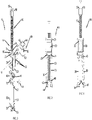
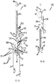
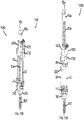
- Rod reducer apparatus 10 includes a housing 20, a plurality of arm members 30, an anvil 40 coupled to a shaft 50, and a button 60.
- rod reducer apparatus 10 may include two arm members 30. Each arm member 30 is insertable through a respective cavity 42 of the anvil 40.
- arm members 30 are pinned in place relative to housing 20 with pins 22.
- arm members 30 may be integrally formed with housing 20 such that, rather than pivoting relative to housing 20, arm members 30 flex relative to housing 20. In such an embodiment, pins 22 may be omitted and arms 30 may be directly attached to housing 20.
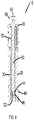
- Pins 22 extend through a respective pin hole 24 of the housing 20 and a respective pin hole 32 (as seen in FIG. 6 ) of each arm member 30.
- Pin holes 32 in combination with pins 22 and pin holes 24 define a pivot axis for first and second arm members 30.
- each arm member 30 has a hook portion 34 at its distal end 36 for engaging a screw housing 100 that is disposed at a proximal end of a bone screw "BS" (as seen in FIGS. 9A and 9B ).
- BS bone screw
- FIGS. 9A and 9B During reduction of a spinal rod 200 ( FIG. 9B ), arm members 30 move towards a parallel configuration, such that hook portion 34 of each respective arm member 30 may engage bone screw "BS" (as seen in FIGS. 9A and 9B ).
- Engagement of hook portion 34 to bone screw "BS” serves to maintain alignment of rod reducer apparatus 10 with respect to the screw housing 100 as spinal rod 200 is reduced into the screw housing 100.
- each arm member 30 pivots with respect to housing 20 about their respective pin holes 32.
- each arm member 30 flexes relative to housing 20 as anvil 40 is translated proximally and distally with respect to housing 20.
- arm members 30 are in a first position, and may be engaged or disengaged from screw housing 100 of bone screw "BS".
- arm members 30 are in a second position, and are configured to be securely engaged with the screw housing 100 of bone screw "BS" ( FIG.
- Shaft 50 has threads thereon and includes a distal portion 54 with an annular groove 52, and a head 58 with a recess 59. It is envisioned that recess 59 may be configured to cooperatively engage with any number of counterpart drive tools known in the art to effect torque driven rotation. For example, recess 59 may be configured as a hex socket (as shown in FIG. 3 ), a hex head 59a (as shown in FIG. 11 ), a Philips head, or slotted head. Shaft 50 is insertable through aperture 46 of anvil 40. Pins 44 are used to maintain the shaft 50 within the anvil 40 by inserting pins 44 through pin holes 48 of anvil 40 such that a portion of each pin 44 resides in the annular groove 52 at the distal end 54 of shaft 50.
- Housing 20 of rod reducer apparatus 10 includes an opening 26.
- housing 20 defines a longitudinal axis "L" (as seen in FIGS. 1, 2 , and 4A ) such that opening 26 coincides with longitudinal axis "L".
- Housing 20 further includes a button cavity 28 disposed therein configured to receive button 60.
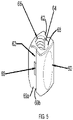
- Button 60 may have an elongated throughhole 64 extending therethrough (as seen in FIG. 5 ) which is alignable with the opening 26 of housing 20 such that shaft 50 is insertable therethrough.
- Housing 20 additionally has pin holes 80 on a top surface 81 and corresponding pin holes 82 (only one pin hole 82 is shown with the other pin hole being identical) on a bottom surface 83.
- Alignment pins 84 (as shown in FIG. 3 ) extend through pin holes 80 and into pin holes 82 respectively. It is envisioned that alignment pins 84 are positioned in grooves 62 which are disposed on opposing sides of button 60 (as seen in FIGS 3 and 5 ). Each groove 62 of button 60 contains a boss 69 disposed thereon, which is utilized as a detent for the placement of button 60 in one of a first or second position.
- button 60 is controlled by placement of the alignment pins 84 within the grooves 62, such that alignment pins 84 are disposed on a first side 69a of bosses 69 or on a second side 69b of bosses 69. It is envisioned that alignment pins 84 additionally aid button 60 to remain within housing 20 during actuation of rod reducer apparatus 10. It is further envisioned that button 60 may be held in place within button cavity 28 by the shaft 50 passing through the opening 26 of housing 20 and the elongated throughhole 64 of button 60. Additionally, it is envisioned that elongated throughhole 64 has a diameter which is larger than a diameter of shaft 50.
- An inner surface of the elongated throughhole 64 has a partially threaded portion 66 disposed thereon configured to receive shaft 50.
- the inner surface of the elongated throughhole 64 also has an unthreaded portion 68, opposite to threaded portion 66, to permit shaft 50 to slide freely therethrough.
- the elongated throughhole 64 may not be perfectly round, but may have an elongated or oval configuration, such that movement of the button 60 along axis "B" (as shown in FIGS. 3 and 4A ) within the button cavity 28 of housing 20 moves the threaded portion 66 of button 60 into and out of engagement with shaft 50.
- button 60 is in the first position when alignment pins 84 are on the first side 69a of bosses 69, and button 60 is in the second position when alignment pins 84 are on the second side 69b of bosses 69. It will be appreciated that bosses 69, within channels 62 act to maintain button 60 into one of either the first or second positions during articulation of rod reducer apparatus 10. Once button 60 is transitioned from the first position to the second position, button 60 remains in the second position until it is manually transitioned back to the first position.
- button 60 is moved along axis "B" with respect to housing 20 and relative to alignment pins 84 such that alignment pins 84 disengage from the first side 69a of the bosses 69 and engage the second side 69b of the bosses.
- alignment pins 84 disengage from the first side 69a of the bosses 69 and engage the second side 69b of the bosses.
- button 60 With button 60 in the first position, threaded portion 66 of button 60 is coupled to the shaft 50, permitting torque driven rotation and proximal and distal translation of the shaft 50 within the opening 26 (as seen in FIG. 4A ) of the housing 20. In the second position, threaded portion 66 of button 60 is uncoupled from shaft 50 permitting free movement of the shaft 50 within the opening 26 of the housing 20. It is envisioned that unthreaded portion 68 of the button 60 may be in near abutment to shaft 50 in the second position.
- proximal and distal movement of shaft 50 and anvil 40 is directly proportional to the threaded configuration of the shaft 50 and the threaded portion 66, and may be thought of as a fine adjustment during reduction of a spinal rod.
- proximal and distal movement of shaft 50 is not constrained allowing rapid movement of the shaft 50 and anvil 40 relative to the housing 20, and may be thought of as a coarse adjustment during reduction of a spinal rod.
- anvil 40 may travel towards and away from housing 20 in unison with the proximal and distal translation of shaft 50.
- threaded rod 50 is manually rotated distally such that anvil 40 simultaneously travels distally with respect to housing 20 into contact with spinal rod 200 to urge spinal rod 200 into screw housing 100 such that spinal rod 200 is securely coupled to screw housing 100.
- threaded rod 50 can slide freely both proximally and distally within opening 26 of housing 20 causing anvil 40 to simultaneously move freely with respect to housing 20 in the proximal and distal directions.
- receiving saddle 49 of anvil 40 is in abutment to an outer surface (not shown) of spinal rod 200.
- receiving saddle 49 is configured to accommodate a range of spinal rod diameters.
- receiving saddle 49 may be adapted to cooperatively engage with a spinal rod 200 having a variance in diameter of between about 3mm to about 8mm, while still achieving the necessary driving force to secure the spinal rod 200 into a bone screw "BS".
- Receiving saddle 49 may be generally arched or convex, but may take the form of any geometric shape adapted to cooperatively engage with and drive a spinal rod during reduction.
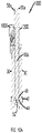
- rod reducer apparatus 1000 includes a housing 1200, arm members 30, anvil 40, shaft 50a, a button 1600, and a spring seat 1700. It should be appreciated that arm members 30 and anvil 40 are the same as discussed above, and for conciseness, will be omitted in discussion of rod reducer apparatus 1000.
- Shaft 50a replaces shaft 50 of the embodiment shown in FIG. 1 .
- Shaft 50a differs from shaft 50 in that head 58a may have a generally smooth outer surface in comparison to the knurled outer surface of head 58 and recess 59 may be replaced with a hexagonal nut 59a for engaging an appropriate driving tool (not shown).
- housing 1200 of rod reducer apparatus 1000 will be further discussed.
- Housing 1200 includes an opening 1202.
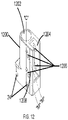
- housing 1200 defines a longitudinal axis "C" (as seen in FIGS. 10 and 12 ) such that opening 26 is coaxially disposed about longitudinal axis "C”.
- Housing 1200 further includes a button cavity 1204 disposed therein configured to receive button 1600.
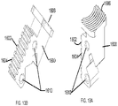
- Button 1600 has a first surface 1602 (as seen in FIGS 13A and 13B ) which is alignable with the opening 1202 of housing 1200 such that shaft 50a may abut the first surface 1602 of button 1600.
- first surface 1602 of button 1600 may have a threaded portion 1604 disposed thereon configured to cooperatively engage with the threads disposed on shaft 50a.
- Button 1600 may further have a second surface 1606, such that an ergonomic grip feature is disposed thereon.
- Button 1600 is coupled to housing 1200 with pins 1608 (as shown in FIG. 11 ). Each pin 1608 extends through a slot 1206 of the housing 1200 and pin holes 1610 of button 1600. Slot 1206 of the housing is adapted to allow translation of button 1600 into and out of engagement with shaft 50a.
- button 1600 is permitted to translate from a first position, wherein the first surface 1602 of button 1600 is in engagement to shaft 50a, into a second position, wherein the first surface 1602 is spaced apart from shaft 50a.
- Slot 1206 is angled diagonally away from the longitudinal axis "C" of housing 1200.
- each pin 1608 moves within slot 1206 along axis "M" (as seen in FIG. 12 ). Axis “M” intersects axis "C” such that an acute angle is defined therebetween. It is further envisioned, that slot 1206 may take any shape which permits button 1600 to translate from the first position to the second position, such as for example, an arcuate path.
- Each pin 1608 additionally aids button 1600 to remain within housing 1200 during actuation of rod reducer apparatus 1000.
- a spring 1702 may be disposed between button 1600 and a spring seat 1700 (seen in FIGS 14A and 14B ) in housing 1200.
- Spring 1702, button 1600, and spring seat 1700 are inserted into button cavity 1204 of housing 1200.
- Spring seat 1700 is held in place relative to housing 1200 with pin 1704.
- Pin 1704 extends through pin hole 1208 of the housing 1200 and pin hole 1706 of spring seat 1700.
- Spring seat 1700 further includes a spring surface 1708, contoured to receive spring 1700.
- Spring 1702 provides a biasing force that urges button 1600 towards the first position, keeping the threaded portion 1604 of button 1600 coupled to the shaft 50a.
- the biasing force of spring 1702 is overcome to achieve the desired position of button 1600, allowing either manual rotation of shaft 50a within opening 1202 of housing 1200 in the first position, or conversely, allowing shaft 50a to freely slide within the opening 1202 of housing 1200 in the second position.
- the threaded portion 1604 of button 1600 is coupled to the shaft 50a in the first position, permitting torque driven rotation and proximal and distal translation of the shaft 50a within the opening 1202 (as seen in FIGS. 15A and 15B ) of the housing 1200.
- threaded portion 1604 of button 1600 is uncoupled from shaft 50a permitting free movement of the shaft 50a within the opening 1202 of the housing 1200.
- proximal and distal movement of shaft 50a and anvil 40 is directly proportional to the threaded configuration of the shaft 50a and the threaded portion 1604, and may be thought of as a fine adjustment during reduction of a spinal rod.
- proximal and distal movement of shaft 50a is not constrained allowing rapid movement of the shaft 50a and anvil 40 relative to the housing 1200, and may be thought of as a coarse adjustment during reduction of a spinal rod.
- rod reducer apparatus 10 Operating a rod reduction apparatus in accordance with the present invention will be described with reference to FIGS. 1-15B . It should be appreciated that the method described below may be performed with rod reducer apparatus 10 in the same fashion as with rod reducer apparatus 1000. Specifically, button 60 of rod reducer apparatus 10 and button 1600 of rod reducer apparatus 1000 interact similarly within respect to the engagement and disengagement with shaft 50 and shaft 50a, respectively, as such, the method described below will be described with reference to rod reducer apparatus 10 for briefness. Differences between operation of rod reducer apparatus 10 and rod reducer apparatus 1000 will be pointed out as necessary.
- a spinal rod and screw construct is assembled in a patient as follows.
- a clinician implants a bone screw "BS” into a spinal vertebra with a screw housings 100 of the bone screw “BS” positioned to receive a spinal rod 200 in a rod retaining seat or saddle portion 110 of the screw housing 100. It is envisioned that a clinician may implant multiple bone screws "BS” into several vertebrae during a procedure. Once the desired number of bone screws "BS” have been implanted, the clinician aligns and manipulates the spinal rod 200 such that a portion of the spinal rod 200 is in proximal relation to the screw housing 100 of each respective bone screw “BS", such that spinal rod 200 creates an unbroken connection between each bone screw "BS”.
- the clinician next positions a rod reducer apparatus 10, 1000 into proximity with each respective bone screw "BS", such that a hook portion 34 of arm members 30 of rod reducer apparatus 10 is in near abutment to the screw housing 100 of each respective bone screw "BS".
- the clinician causes the hook portion 34 of the arm members 30 to grasp, clip, or otherwise affix to the screw housing 100, such that during reduction of spinal rod 200 attachment of rod reducer apparatus 10 to the bone screw "BS", and alignment of spinal rod 200 to the screw housing 100, is maintained.
- spinal rod 200 is positioned between the screw housing 100, the anvil 40, and the arm members 30, and may be in abutment to the anvil 40 (as seen in FIGS. 9A and 15A ) or in abutment to the screw housing 100 (as seen in FIGS. 9B and 15B ).
- the clinician next reduces spinal rod 200 into seat 110 of screw housing 100. Oftentimes there may be 15 mm or more of travel required in order to reduce spinal rod 200 fully within the seat 110 of screw housing 100 such that spinal rod 200 and screw housing 100 can be locked. Manually rotating shaft 50, 50a such a distance can be cumbersome, tedious, and time-consuming.
- the second position of button 60, 1600 of rod reducer apparatus 10, 1000 permits the clinician to perform coarse adjustments and quickly slide shaft 50, 50a distally to position anvil 40 against spinal rod 200 to effect a reduction of spinal rod 200 into screw housing 100.
- shaft 50, 50a With button 60, 1600 of rod reducer apparatus 10, 1000 in the second position, shaft 50, 50a is uncoupled from a threaded portion 66, 1604 of rod reducer apparatus 10, 1000, allowing shaft 50, 50a to freely slid distally through the opening 26, 1202 of the housing 20, 1200. Free translation of shaft 50, 50a permits anvil 40 to rapidly move distally in relation to housing 20, 1200 towards and into abutment with spinal rod 200.
- the clinician freely slides shaft 50, 50a through the opening 26, 1202 of housing 20, 1200 until anvil 40 abuts spinal rod 200.
- each rod reducer apparatus 10, 1000 is mounted to a different bone screw "BS"
- the clinician is able to gradually reduce the spinal rod 200 to a plurality of bone screws "BS” by sequentially reducing each rod reducer apparatus 10, 1000 all or part way until all rod reducer apparatus 10, 1000 have been actuated fully and the spinal rod 200 is reduced into all of the adjacent bone screws "BS".
- the clinician may allow button 1600 to transition to the first position.
- shaft 50 is coupled to the threaded portion 66 of the elongated throughhole 64 of the button 60 such that the clinician may make fine adjustments and manually, or with a surgical tool (not shown), rotate shaft 50 causing anvil 40 to drive spinal rod 200 into securement with screw housing 100.
- shaft 50a in the first position, is coupled to the threaded portion 1604 of the button 1600 such that the clinician may make fine adjustments and manually, or with a surgical tool (not shown), rotate shaft 50a causing anvil 40 to drive spinal rod 200 in secure engagement with screw housing 100.
- the clinician In the first position of either button 60 or button 1600, the clinician is provided a mechanical advantage of torque driven rotation of shaft 50, 50a.
- the clinician may additionally use rod reducer apparatus 10, 1000 to further assist the alignment of spinal rod 200 between multiple bone screws "BS".
- the clinician is provided a mechanical advantage to further bend or shape spinal rod 200 while spinal rod 200 is securely held by both rod reducer apparatus 10, 1000 and the screw housing 100 of the bone screw "BS".
- the clinician may make final adjustments to the spinal rod 200 when connecting spinal rod 200 between multiple bone screws "BS”.
- the clinician may further reduce spinal rod 200 to secure the spinal rod 200 into the screw housing 100 of the bone screw "BS”.
- the clinician may place button 60 or button 1600 in the second position.
- shaft 50, 50a can again slide freely within the opening 26, 1202 of the housing 20, 1200 to permit anvil 40 to quickly and easily move proximally with respect to housing 20, 1200.
- arm members 30 of rod reducer apparatus 10, 1000 may be decoupled from the screw housing 100, permitting the clinician to detach rod reducer apparatus 10, 1000 from the bone screw "BS".
- the clinician may perform the method described above with multiple bone screws "BS", implanted in sequence to a number of vertebrae, to facilitate the reduction of spinal rod 200 into and between multiple screw housings 100. It is envisioned that the clinician may be provided with multiple spinal rods 200. The clinician may perform the method described above to facilitate the reduction of multiple spinal rods 200 into multiple screw housings 100 to a number of vertebrae in sequence. It is further envisioned that the clinician may be provided with multiple bone screws and spinal rods of varying sizes.
- the kit includes a rod reducer apparatus 10, 1000 in a package (not shown).
- the kit may further include a bone screw "BS", a spinal rod 200, an orthopedic tool or device (not shown), and instructions for use.
- the orthopedic tool or device may be a tightening or loosening tool, an alignment tube, or a locking device.
- the kit may include multiple rod reducer apparatus 10, 1000, multiple bone screws "BS”, and multiple spinal rods 200.
- the kit may include a variety of sizes of bone screws "BS” and spinal rods 200.
- the package may include a thermoformed plastic tray and/or other packaging materials within the view of those skilled in the art.
Landscapes
- Health & Medical Sciences (AREA)
- Orthopedic Medicine & Surgery (AREA)
- Neurology (AREA)
- Life Sciences & Earth Sciences (AREA)
- Surgery (AREA)
- Heart & Thoracic Surgery (AREA)
- Engineering & Computer Science (AREA)
- Biomedical Technology (AREA)
- Nuclear Medicine, Radiotherapy & Molecular Imaging (AREA)
- Medical Informatics (AREA)
- Molecular Biology (AREA)
- Animal Behavior & Ethology (AREA)
- General Health & Medical Sciences (AREA)
- Public Health (AREA)
- Veterinary Medicine (AREA)
- Surgical Instruments (AREA)
Claims (9)
- Stabreduzierervorrichtung (1000), umfassend;ein Gehäuse (1200) mit einer Längsachse (c) und einer Öffnung (1202);eine Spindel (50a), die durch die Öffnung angeordnet ist, wobei die Spindel darauf ausgebildete Gewindegänge aufweist;einen Amboss, der an die Spindel gekoppelt ist;einen Knopf (1600) mit einer ersten Oberfläche (1602), die Gewindegänge (1604) beinhaltet, und einer zweiten Oberfläche (1606), wobei der Knopf gleitbar in einem Hohlraum (1204) des Gehäuses angeordnet und zwischen einer ersten Position, in der die Gewindegänge der Spindel mit den Gewindegängen auf dem Knopf im Eingriff stehen, und einer zweiten Position, in der die Gewindegänge der Spindel von den Gewindegängen auf dem Knopf beabstandet sind, wechselbar ist, wobei der Knopf zu der ersten Position hin vorgespannt ist, wobei die Spindel Gewindegänge des Knopfs zusammenwirken in Eingriff nimmt; undein erstes und ein zweites Armelement (30), die funktionsfähig an das Gehäuse gekoppelt sind und dazu konfiguriert sind, eine Knochenschraube (BS) in Eingriff zu nehmen, wobei eine Drehung der Spindel mit dem Knopf in der ersten Position sich in eine Linearbewegung der Spindel in Bezug auf das Gehäuse überträgt und eine Linearbewegung der Spindel mit dem Knopf in der zweiten Position unabhängig von einer Spindeldrehung ist;und dadurch gekennzeichnet, dassdas Gehäuse einen digitalen Schlitz (1206) beinhaltet, entlang dem der Knopf zu der Längsachse zwischen seiner ersten und seiner zweiten Position hin und davon weg durch Übertragung entlang einer Achse (M), die die Längsachse (c) des Gehäuses in einem spitzen Winkel kreuzt, gleitet.
- Stabreduzierervorrichtung nach Anspruch 1, weiterhin umfassend ein Federelement (1702) zum Vorspannen des Knopfs zu der ersten Position hin.
- Stabreduzierervorrichtung nach Anspruch 1, wobei der erste und der zweite Arm zu einer parallelen Konfiguration hin neupositionierbar sind, während der Amboss von dem Gehäuse weg bewegt wird.
- Stabreduzierervorrichtung nach einem der vorhergehenden Ansprüche, wobei das erste und das zweite Armelement schwenkbar an das Gehäuse gekoppelt sind.
- Stabreduzierervorrichtung nach Anspruch 1, 2 oder 3, wobei das erste und das zweite Armelement flexibel an das Gehäuse gekoppelt sind.
- Stabreduzierervorrichtung nach einem der vorhergehenden Ansprüche, wobei der Knopf ein ergonomisches Griffmerkmal aufweist, das auf einer zweiten Oberfläche angeordnet ist.
- Stabreduzierervorrichtung nach einem der vorhergehenden Ansprüche, weiterhin umfassend einen Aufnahmesattel, der auf dem Amboss angeordnet ist, so dass der Aufnahmesattel eine Oberfläche eines Wirbelsäulenstabs zusammenwirkend in Eingriff nimmt.
- Stabreduzierervorrichtung nach Anspruch 7, wobei der Aufnahmesattel allgemein zu einem Bogen gebildet ist und dazu eingerichtet ist, eine Vielfalt von Wirbelsäulendurchmessern in Eingriff zu nehmen.
- Kit, umfassend:
eine Stabreduzierervorrichtung nach einem der vorhergehenden Ansprüche, zusammen mit:mehreren Knochenschrauben (BS) undeinem Wirbelsäulenstab (200).
Applications Claiming Priority (2)
| Application Number | Priority Date | Filing Date | Title |
|---|---|---|---|
| US201361887907P | 2013-10-07 | 2013-10-07 | |
| PCT/US2014/059425 WO2015054200A1 (en) | 2013-10-07 | 2014-10-07 | Rod reducer |
Publications (3)
| Publication Number | Publication Date |
|---|---|
| EP3054871A1 EP3054871A1 (de) | 2016-08-17 |
| EP3054871A4 EP3054871A4 (de) | 2017-08-02 |
| EP3054871B1 true EP3054871B1 (de) | 2022-05-18 |
Family
ID=52777547
Family Applications (1)
| Application Number | Title | Priority Date | Filing Date |
|---|---|---|---|
| EP14852919.1A Active EP3054871B1 (de) | 2013-10-07 | 2014-10-07 | Stabreduzierer |
Country Status (4)
| Country | Link |
|---|---|
| US (1) | US9452000B2 (de) |
| EP (1) | EP3054871B1 (de) |
| AU (1) | AU2014332172B2 (de) |
| WO (1) | WO2015054200A1 (de) |
Cited By (1)
| Publication number | Priority date | Publication date | Assignee | Title |
|---|---|---|---|---|
| US20250255650A1 (en) * | 2024-02-14 | 2025-08-14 | Alphatec Spine, Inc. | Rod reduction instrument and method for spinal surgery |
Families Citing this family (23)
| Publication number | Priority date | Publication date | Assignee | Title |
|---|---|---|---|---|
| US8998952B2 (en) * | 2004-02-17 | 2015-04-07 | Globus Medical, Inc. | Facet joint replacement instruments and methods |
| US8545505B2 (en) * | 2010-01-15 | 2013-10-01 | Pioneer Surgical Technology, Inc. | Low friction rod persuader |
| US8202274B2 (en) * | 2010-06-18 | 2012-06-19 | Spine Wave, Inc. | Apparatus and method for detecting a connecting rod during percutaneous surgery |
| US9943344B2 (en) | 2015-01-15 | 2018-04-17 | K2M, Inc. | Rod reducer |
| EP3288473B1 (de) | 2015-04-30 | 2022-12-28 | K2M, Inc. | Stabreduzierer |
| US10117678B2 (en) | 2015-05-28 | 2018-11-06 | K2M, Inc. | Surgical system for bone screw insertion and rod reduction |
| DE102016101822A1 (de) | 2016-02-02 | 2017-08-03 | Aesculap Ag | Instrument zum Führen eines Stabs in eine Implantataufnahme |
| DE102016106608A1 (de) * | 2016-04-11 | 2017-10-12 | Aesculap Ag | Instrument zum Führen eines Stabs in eine Implantataufnahme |
| JP7037487B2 (ja) * | 2016-02-02 | 2022-03-16 | エースクラップ アーゲー | インプラントホルダ内にロッドを案内する器具 |
| US10524843B2 (en) | 2016-05-06 | 2020-01-07 | K2M, Inc. | Rotation shaft for a rod reducer |
| US10952778B2 (en) | 2016-10-18 | 2021-03-23 | K2M, Inc. | Rod reducer |
| CN106510834B (zh) * | 2016-11-22 | 2020-05-12 | 常州华森医疗器械有限公司 | 椎弓根固定系统用安装工具 |
| US10779866B2 (en) | 2016-12-29 | 2020-09-22 | K2M, Inc. | Rod reducer assembly |
| US10485590B2 (en) | 2017-01-18 | 2019-11-26 | K2M, Inc. | Rod reducing device |
| US11730522B2 (en) | 2017-10-20 | 2023-08-22 | Spine Wave, Inc. | Threaded spinal rod reducer |
| US10966762B2 (en) * | 2017-12-15 | 2021-04-06 | Medos International Sarl | Unilateral implant holders and related methods |
| USD1004774S1 (en) | 2019-03-21 | 2023-11-14 | Medos International Sarl | Kerrison rod reducer |
| US11291482B2 (en) | 2019-03-21 | 2022-04-05 | Medos International Sarl | Rod reducers and related methods |
| US11291481B2 (en) | 2019-03-21 | 2022-04-05 | Medos International Sarl | Rod reducers and related methods |
| US11553947B2 (en) * | 2019-07-16 | 2023-01-17 | Aesculap Implant Systems, Llc | Spinal deformity sequential persuader |
| WO2022096752A1 (en) | 2020-11-09 | 2022-05-12 | Medos International Sarl | Biplanar forceps reducers |
| AU2022390426A1 (en) | 2021-11-19 | 2024-07-04 | Medos International Sarl | Reducer locking mechanisms |
| CN116693555B (zh) | 2022-02-25 | 2025-07-04 | 上海赛默罗生物科技有限公司 | 咪唑并哒嗪类衍生物、其制备方法、药物组合物和用途 |
Family Cites Families (94)
| Publication number | Priority date | Publication date | Assignee | Title |
|---|---|---|---|---|
| US2248054A (en) | 1939-06-07 | 1941-07-08 | Becker Joseph | Screw driver |
| US3604487A (en) | 1969-03-10 | 1971-09-14 | Richard S Gilbert | Orthopedic screw driving means |
| US4156424A (en) | 1978-05-01 | 1979-05-29 | Burgin Kermit H | Locking adjustable speculum |
| US5454365A (en) | 1990-11-05 | 1995-10-03 | Bonutti; Peter M. | Mechanically expandable arthroscopic retractors |
| AU8519891A (en) | 1990-08-01 | 1992-03-02 | Staktek Corporation | Ultra high density integrated circuit packages, method and apparatus |
| US5020519A (en) | 1990-12-07 | 1991-06-04 | Zimmer, Inc. | Sagittal approximator |
| US5364397A (en) | 1993-06-01 | 1994-11-15 | Zimmer, Inc. | Spinal coupler seater with dual jaws and an independent plunger |
| US5431658A (en) | 1994-02-14 | 1995-07-11 | Moskovich; Ronald | Facilitator for vertebrae grafts and prostheses |
| US5466243A (en) | 1994-02-17 | 1995-11-14 | Arthrex, Inc. | Method and apparatus for installing a suture anchor through a hollow cannulated grasper |
| US5529571A (en) | 1995-01-17 | 1996-06-25 | Daniel; Elie C. | Surgical retractor/compressor |
| US5720751A (en) | 1996-11-27 | 1998-02-24 | Jackson; Roger P. | Tools for use in seating spinal rods in open ended implants |
| US5951564A (en) | 1996-12-18 | 1999-09-14 | Bristol-Myers Squibb Company | Orthopaedic positioning apparatus |
| US5910141A (en) | 1997-02-12 | 1999-06-08 | Sdgi Holdings, Inc. | Rod introduction apparatus |
| US5944658A (en) | 1997-09-23 | 1999-08-31 | Koros; Tibor B. | Lumbar spinal fusion retractor and distractor system |
| US6123707A (en) | 1999-01-13 | 2000-09-26 | Spinal Concepts, Inc. | Reduction instrument |
| AU767503B2 (en) | 1999-03-30 | 2003-11-13 | Howmedica Osteonics Corp. | Apparatus for spinal stabilization |
| JP2003501189A (ja) | 1999-06-11 | 2003-01-14 | コーニンクレッカ フィリップス エレクトロニクス エヌ ヴィ | 脱毛装置と冷却装置とを有する脱毛システム |
| US6200322B1 (en) | 1999-08-13 | 2001-03-13 | Sdgi Holdings, Inc. | Minimal exposure posterior spinal interbody instrumentation and technique |
| US6530929B1 (en) | 1999-10-20 | 2003-03-11 | Sdgi Holdings, Inc. | Instruments for stabilization of bony structures |
| JP3936118B2 (ja) | 2000-03-28 | 2007-06-27 | 昭和医科工業株式会社 | ロッドグリッパー |
| US6488682B2 (en) | 2000-03-28 | 2002-12-03 | Showa Ika Kohgyo Co., Ltd. | Spinal implant, driver tool and nut guide |
| US6743231B1 (en) | 2000-10-02 | 2004-06-01 | Sulzer Spine-Tech Inc. | Temporary spinal fixation apparatuses and methods |
| US6929606B2 (en) | 2001-01-29 | 2005-08-16 | Depuy Spine, Inc. | Retractor and method for spinal pedicle screw placement |
| US6616605B2 (en) | 2001-02-15 | 2003-09-09 | Genesee Biomedical, Inc. | Quadretractor and method of use |
| US6440133B1 (en) | 2001-07-03 | 2002-08-27 | Sdgi Holdings, Inc. | Rod reducer instruments and methods |
| US6746449B2 (en) | 2001-09-12 | 2004-06-08 | Spinal Concepts, Inc. | Spinal rod translation instrument |
| JP4346439B2 (ja) | 2001-10-05 | 2009-10-21 | タイコ ヘルスケア グループ エルピー | 外科的ファスナーデバイスのための傾斜トップアンビル |
| US6923814B1 (en) | 2001-10-30 | 2005-08-02 | Nuvasive, Inc. | System and methods for cervical spinal fusion |
| US6660006B2 (en) | 2002-04-17 | 2003-12-09 | Stryker Spine | Rod persuader |
| JP4559848B2 (ja) * | 2002-05-08 | 2010-10-13 | リトランド,ステイーヴン | 動的固定装置及びその使用法 |
| US7278995B2 (en) | 2002-06-04 | 2007-10-09 | Howmedica Osteonics Corp. | Apparatus for securing a spinal rod system |
| US6648888B1 (en) | 2002-09-06 | 2003-11-18 | Endius Incorporated | Surgical instrument for moving a vertebra |
| US6849064B2 (en) | 2002-10-25 | 2005-02-01 | James S. Hamada | Minimal access lumbar diskectomy instrumentation and method |
| US7946982B2 (en) | 2002-10-25 | 2011-05-24 | K2M, Inc. | Minimal incision maximal access MIS spine instrumentation and method |
| EP3222231A1 (de) | 2002-10-30 | 2017-09-27 | Zimmer Spine, Inc. | Spinaler stabilisierungssystemeinsatz und verfahren |
| EP1567064B1 (de) | 2002-11-23 | 2012-05-09 | George Frey | Distraktions- und retraktionssystem für die wirbelsäulenchirurgie |
| US7621918B2 (en) | 2004-11-23 | 2009-11-24 | Jackson Roger P | Spinal fixation tool set and method |
| US7473267B2 (en) | 2003-04-25 | 2009-01-06 | Warsaw Orthopedic, Inc. | System and method for minimally invasive posterior fixation |
| US7156849B2 (en) | 2003-06-16 | 2007-01-02 | Depuy Spine, Inc. | Rod reduction nut and driver tool |
| US20040267275A1 (en) | 2003-06-26 | 2004-12-30 | Cournoyer John R. | Spinal implant holder and rod reduction systems and methods |
| US20050059969A1 (en) * | 2003-09-17 | 2005-03-17 | Depuy Acromed, Inc. | Rod approximator |
| US20050065516A1 (en) | 2003-09-24 | 2005-03-24 | Tae-Ahn Jahng | Method and apparatus for flexible fixation of a spine |
| US8002798B2 (en) | 2003-09-24 | 2011-08-23 | Stryker Spine | System and method for spinal implant placement |
| US7955355B2 (en) | 2003-09-24 | 2011-06-07 | Stryker Spine | Methods and devices for improving percutaneous access in minimally invasive surgeries |
| US7588588B2 (en) | 2003-10-21 | 2009-09-15 | Innovative Spinal Technologies | System and method for stabilizing of internal structures |
| US7588575B2 (en) | 2003-10-21 | 2009-09-15 | Innovative Spinal Technologies | Extension for use with stabilization systems for internal structures |
| US7527638B2 (en) | 2003-12-16 | 2009-05-05 | Depuy Spine, Inc. | Methods and devices for minimally invasive spinal fixation element placement |
| US7179261B2 (en) | 2003-12-16 | 2007-02-20 | Depuy Spine, Inc. | Percutaneous access devices and bone anchor assemblies |
| EP1694226B1 (de) | 2003-12-17 | 2009-09-02 | DePuy Spine, Inc. | Instrumente und verfahren für den knochenankereingriff und die wirbelstangenreduktion |
| US8123757B2 (en) | 2003-12-31 | 2012-02-28 | Depuy Spine, Inc. | Inserter instrument and implant clip |
| US7625379B2 (en) | 2004-01-26 | 2009-12-01 | Warsaw Orthopedic, Inc. | Methods and instrumentation for inserting intervertebral grafts and devices |
| JP4762918B2 (ja) | 2004-02-06 | 2011-08-31 | デピュイ・スパイン・インコーポレイテッド | 脊椎固定要素を挿入する器械および方法 |
| US7611517B2 (en) | 2004-02-27 | 2009-11-03 | Warsaw Orthopedic, Inc. | Rod reducer |
| US7160300B2 (en) | 2004-02-27 | 2007-01-09 | Jackson Roger P | Orthopedic implant rod reduction tool set and method |
| JP4213609B2 (ja) | 2004-03-09 | 2009-01-21 | 昭和医科工業株式会社 | ロッド固定用補助器具 |
| US7547318B2 (en) | 2004-03-19 | 2009-06-16 | Depuy Spine, Inc. | Spinal fixation element and methods |
| US7226453B2 (en) | 2004-03-31 | 2007-06-05 | Depuy Spine, Inc. | Instrument for inserting, adjusting and removing pedicle screws and other orthopedic implants |
| US7491207B2 (en) | 2004-04-12 | 2009-02-17 | Synthes Usa, Llc | Rod persuader |
| US20050277934A1 (en) * | 2004-06-10 | 2005-12-15 | Vardiman Arnold B | Rod delivery device and method |
| EP1841374A2 (de) | 2004-07-06 | 2007-10-10 | Synthes GmbH | Einführinstrument für eine wirbelsäulenstange |
| US7591836B2 (en) | 2004-07-30 | 2009-09-22 | Zimmer Spine, Inc. | Surgical devices and methods for vertebral shifting utilizing spinal fixation systems |
| US7637914B2 (en) | 2004-08-04 | 2009-12-29 | Leslie Stern | Surgical base unit and retractor support mechanism |
| US7572281B2 (en) | 2004-08-06 | 2009-08-11 | Depuy Spine, Inc. | Instrument for guiding a rod into an implant in a spinal fixation system |
| US7462182B2 (en) | 2004-08-10 | 2008-12-09 | Warsaw Orthopedic, Inc. | Reducing instrument for spinal surgery |
| US7651502B2 (en) | 2004-09-24 | 2010-01-26 | Jackson Roger P | Spinal fixation tool set and method for rod reduction and fastener insertion |
| US7666189B2 (en) | 2004-09-29 | 2010-02-23 | Synthes Usa, Llc | Less invasive surgical system and methods |
| US20060089651A1 (en) | 2004-10-26 | 2006-04-27 | Trudeau Jeffrey L | Apparatus and method for anchoring a surgical rod |
| US7481813B1 (en) | 2004-11-19 | 2009-01-27 | Alphatec Spine, Inc. | Securing device and corresponding methods thereof for bone fixation systems |
| US7799031B2 (en) * | 2005-02-09 | 2010-09-21 | Warsaw Orthopedic, Inc. | Reducing instrument for spinal surgery |
| US7951175B2 (en) | 2005-03-04 | 2011-05-31 | Depuy Spine, Inc. | Instruments and methods for manipulating a vertebra |
| ES2318917B1 (es) | 2005-03-30 | 2010-02-04 | Sdgi Holdings Inc. | Sistema para la correccion tridimensional de la curvatura de la columna vertebral en problemas de escoliosis por alineacion coplanar de los tornillos pediculares. |
| US7491208B2 (en) | 2005-04-28 | 2009-02-17 | Warsaw Orthopedic, Inc. | Instrument and method for guiding surgical implants and instruments during surgery |
| US7608081B2 (en) | 2005-05-23 | 2009-10-27 | Custom Spine, Inc. | Rod reducer |
| US7572264B2 (en) | 2005-06-28 | 2009-08-11 | Warsaw Orthopedic, Inc. | Driver instrument for use in a surgical application |
| US7846093B2 (en) * | 2005-09-26 | 2010-12-07 | K2M, Inc. | Minimally invasive retractor and methods of use |
| US7988694B2 (en) | 2005-09-29 | 2011-08-02 | K2M, Inc. | Spinal fixation system having locking and unlocking devices for use with a multi-planar, taper lock screw |
| US7575581B2 (en) | 2005-12-07 | 2009-08-18 | Blackstone Medical, Inc. | Device for holding and inserting one or more components of a pedicle screw assembly |
| US7497869B2 (en) | 2006-01-27 | 2009-03-03 | Warsaw Orthopedic, Inc. | Methods and devices for a minimally invasive placement of a rod within a patient |
| US7520879B2 (en) | 2006-02-07 | 2009-04-21 | Warsaw Orthopedic, Inc. | Surgical instruments and techniques for percutaneous placement of spinal stabilization elements |
| US7655008B2 (en) | 2006-02-09 | 2010-02-02 | Warsaw Orthopedic, Inc. | Methods and instruments for spinal derotation |
| US7931654B2 (en) | 2006-03-09 | 2011-04-26 | K2M, Inc. | Dual action rod reducing and locking device and method |
| US7927334B2 (en) | 2006-04-11 | 2011-04-19 | Warsaw Orthopedic, Inc. | Multi-directional rod reducer instrument and method |
| US7922749B2 (en) | 2006-04-14 | 2011-04-12 | Warsaw Orthopedic, Inc. | Reducing device |
| US8192438B2 (en) | 2006-05-18 | 2012-06-05 | Phygen, LLC. | Rod reducer |
| US8230863B2 (en) | 2006-05-30 | 2012-07-31 | Mini-Lap Technologies, Inc. | Platform for fixing surgical instruments during surgery |
| US20080015601A1 (en) | 2006-06-14 | 2008-01-17 | Michael Castro | Reduction device and method of use |
| US20080172062A1 (en) | 2007-01-12 | 2008-07-17 | Depuy Spine, Inc. | Bone anchor manipulation device |
| US8961523B2 (en) | 2007-07-13 | 2015-02-24 | K2M, Inc. | Rod reduction device and method of use |
| US7887541B2 (en) | 2007-07-26 | 2011-02-15 | Depuy Spine, Inc. | Spinal rod reduction instruments and methods for use |
| US8303595B2 (en) | 2008-06-11 | 2012-11-06 | K2M, Inc. | Rod reduction device |
| JP5543964B2 (ja) * | 2008-06-11 | 2014-07-09 | ケー2エム, インコーポレイテッド | ロッド整復装置 |
| WO2009158707A1 (en) | 2008-06-27 | 2009-12-30 | K2M, Inc. | System and method for performing spinal surgery |
| WO2012045070A1 (en) | 2010-10-01 | 2012-04-05 | K2M, Inc. | Devices, systems, and methods for performing spinal surgery |
| US20120191144A1 (en) * | 2011-01-26 | 2012-07-26 | Warsaw Orthopedic, Inc | Instrument for reduction of a vertebral rod and method of use |
-
2014
- 2014-10-07 EP EP14852919.1A patent/EP3054871B1/de active Active
- 2014-10-07 US US14/508,180 patent/US9452000B2/en not_active Expired - Fee Related
- 2014-10-07 AU AU2014332172A patent/AU2014332172B2/en active Active
- 2014-10-07 WO PCT/US2014/059425 patent/WO2015054200A1/en not_active Ceased
Cited By (3)
| Publication number | Priority date | Publication date | Assignee | Title |
|---|---|---|---|---|
| US20250255650A1 (en) * | 2024-02-14 | 2025-08-14 | Alphatec Spine, Inc. | Rod reduction instrument and method for spinal surgery |
| WO2025174754A1 (en) * | 2024-02-14 | 2025-08-21 | Alphatec Spine, Inc. | Rod reduction instrument |
| US12471965B2 (en) * | 2024-02-14 | 2025-11-18 | Alphatec Spine, Inc. | Rod reduction instrument and method for spinal surgery |
Also Published As
| Publication number | Publication date |
|---|---|
| US9452000B2 (en) | 2016-09-27 |
| US20150100097A1 (en) | 2015-04-09 |
| WO2015054200A1 (en) | 2015-04-16 |
| AU2014332172B2 (en) | 2019-05-30 |
| EP3054871A1 (de) | 2016-08-17 |
| EP3054871A4 (de) | 2017-08-02 |
| AU2014332172A1 (en) | 2016-04-28 |
Similar Documents
| Publication | Publication Date | Title |
|---|---|---|
| US9452000B2 (en) | Rod reducer | |
| US20150100098A1 (en) | Rod reducer | |
| US11903621B2 (en) | Rod reduction device and method of use | |
| US11350973B2 (en) | Rod reducer | |
| US9247969B2 (en) | Rod reduction device | |
| US9820779B2 (en) | Spinal stabilization system | |
| US9498261B2 (en) | Laminar hook insertion device | |
| EP3241511B1 (de) | Drehwelle für einen stabreduzierer | |
| EP2730242A1 (de) | Wirbelsäulenstabilisierungssystem | |
| JP2018517507A (ja) | 後方脊椎手術のための脊椎固定式標的化システムおよび方法 | |
| EP3199115A1 (de) | System zur positionierung spinaler implantate | |
| EP3288473B1 (de) | Stabreduzierer | |
| AU2016203448A1 (en) | Surgical system for bone screw insertion and rod reduction |
Legal Events
| Date | Code | Title | Description |
|---|---|---|---|
| PUAI | Public reference made under article 153(3) epc to a published international application that has entered the european phase |
Free format text: ORIGINAL CODE: 0009012 |
|
| 17P | Request for examination filed |
Effective date: 20160506 |
|
| AK | Designated contracting states |
Kind code of ref document: A1 Designated state(s): AL AT BE BG CH CY CZ DE DK EE ES FI FR GB GR HR HU IE IS IT LI LT LU LV MC MK MT NL NO PL PT RO RS SE SI SK SM TR |
|
| AX | Request for extension of the european patent |
Extension state: BA ME |
|
| DAX | Request for extension of the european patent (deleted) | ||
| RIC1 | Information provided on ipc code assigned before grant |
Ipc: A61B 17/58 20060101ALI20170303BHEP Ipc: A61B 17/70 20060101ALI20170303BHEP Ipc: A61B 17/00 20060101ALI20170303BHEP Ipc: A61B 17/56 20060101AFI20170303BHEP |
|
| RIC1 | Information provided on ipc code assigned before grant |
Ipc: A61B 17/70 20060101ALI20170622BHEP Ipc: A61B 17/58 20060101ALI20170622BHEP Ipc: A61B 17/00 20060101ALI20170622BHEP Ipc: A61B 17/56 20060101AFI20170622BHEP |
|
| A4 | Supplementary search report drawn up and despatched |
Effective date: 20170630 |
|
| RAP1 | Party data changed (applicant data changed or rights of an application transferred) |
Owner name: K2M, INC. |
|
| GRAP | Despatch of communication of intention to grant a patent |
Free format text: ORIGINAL CODE: EPIDOSNIGR1 |
|
| STAA | Information on the status of an ep patent application or granted ep patent |
Free format text: STATUS: GRANT OF PATENT IS INTENDED |
|
| INTG | Intention to grant announced |
Effective date: 20211216 |
|
| GRAS | Grant fee paid |
Free format text: ORIGINAL CODE: EPIDOSNIGR3 |
|
| GRAA | (expected) grant |
Free format text: ORIGINAL CODE: 0009210 |
|
| STAA | Information on the status of an ep patent application or granted ep patent |
Free format text: STATUS: THE PATENT HAS BEEN GRANTED |
|
| AK | Designated contracting states |
Kind code of ref document: B1 Designated state(s): AL AT BE BG CH CY CZ DE DK EE ES FI FR GB GR HR HU IE IS IT LI LT LU LV MC MK MT NL NO PL PT RO RS SE SI SK SM TR |
|
| REG | Reference to a national code |
Ref country code: GB Ref legal event code: FG4D |
|
| REG | Reference to a national code |
Ref country code: CH Ref legal event code: EP |
|
| REG | Reference to a national code |
Ref country code: IE Ref legal event code: FG4D |
|
| REG | Reference to a national code |
Ref country code: DE Ref legal event code: R096 Ref document number: 602014083803 Country of ref document: DE |
|
| REG | Reference to a national code |
Ref country code: AT Ref legal event code: REF Ref document number: 1492718 Country of ref document: AT Kind code of ref document: T Effective date: 20220615 |
|
| REG | Reference to a national code |
Ref country code: LT Ref legal event code: MG9D |
|
| REG | Reference to a national code |
Ref country code: NL Ref legal event code: MP Effective date: 20220518 |
|
| REG | Reference to a national code |
Ref country code: AT Ref legal event code: MK05 Ref document number: 1492718 Country of ref document: AT Kind code of ref document: T Effective date: 20220518 |
|
| PG25 | Lapsed in a contracting state [announced via postgrant information from national office to epo] |
Ref country code: SE Free format text: LAPSE BECAUSE OF FAILURE TO SUBMIT A TRANSLATION OF THE DESCRIPTION OR TO PAY THE FEE WITHIN THE PRESCRIBED TIME-LIMIT Effective date: 20220518 Ref country code: PT Free format text: LAPSE BECAUSE OF FAILURE TO SUBMIT A TRANSLATION OF THE DESCRIPTION OR TO PAY THE FEE WITHIN THE PRESCRIBED TIME-LIMIT Effective date: 20220919 Ref country code: NO Free format text: LAPSE BECAUSE OF FAILURE TO SUBMIT A TRANSLATION OF THE DESCRIPTION OR TO PAY THE FEE WITHIN THE PRESCRIBED TIME-LIMIT Effective date: 20220818 Ref country code: NL Free format text: LAPSE BECAUSE OF FAILURE TO SUBMIT A TRANSLATION OF THE DESCRIPTION OR TO PAY THE FEE WITHIN THE PRESCRIBED TIME-LIMIT Effective date: 20220518 Ref country code: LT Free format text: LAPSE BECAUSE OF FAILURE TO SUBMIT A TRANSLATION OF THE DESCRIPTION OR TO PAY THE FEE WITHIN THE PRESCRIBED TIME-LIMIT Effective date: 20220518 Ref country code: HR Free format text: LAPSE BECAUSE OF FAILURE TO SUBMIT A TRANSLATION OF THE DESCRIPTION OR TO PAY THE FEE WITHIN THE PRESCRIBED TIME-LIMIT Effective date: 20220518 Ref country code: GR Free format text: LAPSE BECAUSE OF FAILURE TO SUBMIT A TRANSLATION OF THE DESCRIPTION OR TO PAY THE FEE WITHIN THE PRESCRIBED TIME-LIMIT Effective date: 20220819 Ref country code: FI Free format text: LAPSE BECAUSE OF FAILURE TO SUBMIT A TRANSLATION OF THE DESCRIPTION OR TO PAY THE FEE WITHIN THE PRESCRIBED TIME-LIMIT Effective date: 20220518 Ref country code: ES Free format text: LAPSE BECAUSE OF FAILURE TO SUBMIT A TRANSLATION OF THE DESCRIPTION OR TO PAY THE FEE WITHIN THE PRESCRIBED TIME-LIMIT Effective date: 20220518 Ref country code: BG Free format text: LAPSE BECAUSE OF FAILURE TO SUBMIT A TRANSLATION OF THE DESCRIPTION OR TO PAY THE FEE WITHIN THE PRESCRIBED TIME-LIMIT Effective date: 20220818 Ref country code: AT Free format text: LAPSE BECAUSE OF FAILURE TO SUBMIT A TRANSLATION OF THE DESCRIPTION OR TO PAY THE FEE WITHIN THE PRESCRIBED TIME-LIMIT Effective date: 20220518 |
|
| PG25 | Lapsed in a contracting state [announced via postgrant information from national office to epo] |
Ref country code: RS Free format text: LAPSE BECAUSE OF FAILURE TO SUBMIT A TRANSLATION OF THE DESCRIPTION OR TO PAY THE FEE WITHIN THE PRESCRIBED TIME-LIMIT Effective date: 20220518 Ref country code: PL Free format text: LAPSE BECAUSE OF FAILURE TO SUBMIT A TRANSLATION OF THE DESCRIPTION OR TO PAY THE FEE WITHIN THE PRESCRIBED TIME-LIMIT Effective date: 20220518 Ref country code: LV Free format text: LAPSE BECAUSE OF FAILURE TO SUBMIT A TRANSLATION OF THE DESCRIPTION OR TO PAY THE FEE WITHIN THE PRESCRIBED TIME-LIMIT Effective date: 20220518 Ref country code: IS Free format text: LAPSE BECAUSE OF FAILURE TO SUBMIT A TRANSLATION OF THE DESCRIPTION OR TO PAY THE FEE WITHIN THE PRESCRIBED TIME-LIMIT Effective date: 20220918 |
|
| PG25 | Lapsed in a contracting state [announced via postgrant information from national office to epo] |
Ref country code: CZ Free format text: LAPSE BECAUSE OF FAILURE TO SUBMIT A TRANSLATION OF THE DESCRIPTION OR TO PAY THE FEE WITHIN THE PRESCRIBED TIME-LIMIT Effective date: 20220518 Ref country code: SM Free format text: LAPSE BECAUSE OF FAILURE TO SUBMIT A TRANSLATION OF THE DESCRIPTION OR TO PAY THE FEE WITHIN THE PRESCRIBED TIME-LIMIT Effective date: 20220518 Ref country code: SK Free format text: LAPSE BECAUSE OF FAILURE TO SUBMIT A TRANSLATION OF THE DESCRIPTION OR TO PAY THE FEE WITHIN THE PRESCRIBED TIME-LIMIT Effective date: 20220518 Ref country code: RO Free format text: LAPSE BECAUSE OF FAILURE TO SUBMIT A TRANSLATION OF THE DESCRIPTION OR TO PAY THE FEE WITHIN THE PRESCRIBED TIME-LIMIT Effective date: 20220518 Ref country code: EE Free format text: LAPSE BECAUSE OF FAILURE TO SUBMIT A TRANSLATION OF THE DESCRIPTION OR TO PAY THE FEE WITHIN THE PRESCRIBED TIME-LIMIT Effective date: 20220518 Ref country code: DK Free format text: LAPSE BECAUSE OF FAILURE TO SUBMIT A TRANSLATION OF THE DESCRIPTION OR TO PAY THE FEE WITHIN THE PRESCRIBED TIME-LIMIT Effective date: 20220518 |
|
| REG | Reference to a national code |
Ref country code: DE Ref legal event code: R097 Ref document number: 602014083803 Country of ref document: DE |
|
| PLBE | No opposition filed within time limit |
Free format text: ORIGINAL CODE: 0009261 |
|
| STAA | Information on the status of an ep patent application or granted ep patent |
Free format text: STATUS: NO OPPOSITION FILED WITHIN TIME LIMIT |
|
| PG25 | Lapsed in a contracting state [announced via postgrant information from national office to epo] |
Ref country code: AL Free format text: LAPSE BECAUSE OF FAILURE TO SUBMIT A TRANSLATION OF THE DESCRIPTION OR TO PAY THE FEE WITHIN THE PRESCRIBED TIME-LIMIT Effective date: 20220518 |
|
| 26N | No opposition filed |
Effective date: 20230221 |
|
| PG25 | Lapsed in a contracting state [announced via postgrant information from national office to epo] |
Ref country code: SI Free format text: LAPSE BECAUSE OF FAILURE TO SUBMIT A TRANSLATION OF THE DESCRIPTION OR TO PAY THE FEE WITHIN THE PRESCRIBED TIME-LIMIT Effective date: 20220518 Ref country code: MC Free format text: LAPSE BECAUSE OF FAILURE TO SUBMIT A TRANSLATION OF THE DESCRIPTION OR TO PAY THE FEE WITHIN THE PRESCRIBED TIME-LIMIT Effective date: 20220518 |
|
| REG | Reference to a national code |
Ref country code: CH Ref legal event code: PL |
|
| REG | Reference to a national code |
Ref country code: BE Ref legal event code: MM Effective date: 20221031 |
|
| P01 | Opt-out of the competence of the unified patent court (upc) registered |
Effective date: 20230522 |
|
| PG25 | Lapsed in a contracting state [announced via postgrant information from national office to epo] |
Ref country code: LU Free format text: LAPSE BECAUSE OF NON-PAYMENT OF DUE FEES Effective date: 20221007 |
|
| PG25 | Lapsed in a contracting state [announced via postgrant information from national office to epo] |
Ref country code: LI Free format text: LAPSE BECAUSE OF NON-PAYMENT OF DUE FEES Effective date: 20221031 Ref country code: CH Free format text: LAPSE BECAUSE OF NON-PAYMENT OF DUE FEES Effective date: 20221031 |
|
| PG25 | Lapsed in a contracting state [announced via postgrant information from national office to epo] |
Ref country code: BE Free format text: LAPSE BECAUSE OF NON-PAYMENT OF DUE FEES Effective date: 20221031 |
|
| PG25 | Lapsed in a contracting state [announced via postgrant information from national office to epo] |
Ref country code: IE Free format text: LAPSE BECAUSE OF NON-PAYMENT OF DUE FEES Effective date: 20221007 |
|
| PG25 | Lapsed in a contracting state [announced via postgrant information from national office to epo] |
Ref country code: IT Free format text: LAPSE BECAUSE OF FAILURE TO SUBMIT A TRANSLATION OF THE DESCRIPTION OR TO PAY THE FEE WITHIN THE PRESCRIBED TIME-LIMIT Effective date: 20220518 |
|
| PG25 | Lapsed in a contracting state [announced via postgrant information from national office to epo] |
Ref country code: HU Free format text: LAPSE BECAUSE OF FAILURE TO SUBMIT A TRANSLATION OF THE DESCRIPTION OR TO PAY THE FEE WITHIN THE PRESCRIBED TIME-LIMIT; INVALID AB INITIO Effective date: 20141007 |
|
| PG25 | Lapsed in a contracting state [announced via postgrant information from national office to epo] |
Ref country code: CY Free format text: LAPSE BECAUSE OF FAILURE TO SUBMIT A TRANSLATION OF THE DESCRIPTION OR TO PAY THE FEE WITHIN THE PRESCRIBED TIME-LIMIT Effective date: 20220511 |
|
| PG25 | Lapsed in a contracting state [announced via postgrant information from national office to epo] |
Ref country code: MK Free format text: LAPSE BECAUSE OF FAILURE TO SUBMIT A TRANSLATION OF THE DESCRIPTION OR TO PAY THE FEE WITHIN THE PRESCRIBED TIME-LIMIT Effective date: 20220511 |
|
| PG25 | Lapsed in a contracting state [announced via postgrant information from national office to epo] |
Ref country code: MT Free format text: LAPSE BECAUSE OF FAILURE TO SUBMIT A TRANSLATION OF THE DESCRIPTION OR TO PAY THE FEE WITHIN THE PRESCRIBED TIME-LIMIT Effective date: 20220511 |
|
| PG25 | Lapsed in a contracting state [announced via postgrant information from national office to epo] |
Ref country code: BG Free format text: LAPSE BECAUSE OF FAILURE TO SUBMIT A TRANSLATION OF THE DESCRIPTION OR TO PAY THE FEE WITHIN THE PRESCRIBED TIME-LIMIT Effective date: 20220518 |
|
| PG25 | Lapsed in a contracting state [announced via postgrant information from national office to epo] |
Ref country code: BG Free format text: LAPSE BECAUSE OF FAILURE TO SUBMIT A TRANSLATION OF THE DESCRIPTION OR TO PAY THE FEE WITHIN THE PRESCRIBED TIME-LIMIT Effective date: 20220518 |
|
| REG | Reference to a national code |
Ref country code: DE Ref legal event code: R081 Ref document number: 602014083803 Country of ref document: DE Owner name: VB SPINE US OPCO LLC, WILMINGTON, US Free format text: FORMER OWNER: STRYKER CORPORATION, PORTAGE, MI, US Ref country code: DE Ref legal event code: R081 Ref document number: 602014083803 Country of ref document: DE Owner name: VB SPINE US OPCO LLC, WILMINGTON, US Free format text: FORMER OWNER: K2M, INC., LEESBURG, VA, US |
|
| REG | Reference to a national code |
Ref country code: GB Ref legal event code: 732E Free format text: REGISTERED BETWEEN 20250626 AND 20250702 |
|
| PGFP | Annual fee paid to national office [announced via postgrant information from national office to epo] |
Ref country code: GB Payment date: 20250911 Year of fee payment: 12 |
|
| PGFP | Annual fee paid to national office [announced via postgrant information from national office to epo] |
Ref country code: FR Payment date: 20250922 Year of fee payment: 12 |
|
| PG25 | Lapsed in a contracting state [announced via postgrant information from national office to epo] |
Ref country code: TR Free format text: LAPSE BECAUSE OF FAILURE TO SUBMIT A TRANSLATION OF THE DESCRIPTION OR TO PAY THE FEE WITHIN THE PRESCRIBED TIME-LIMIT Effective date: 20220518 |
|
| PGFP | Annual fee paid to national office [announced via postgrant information from national office to epo] |
Ref country code: DE Payment date: 20250916 Year of fee payment: 12 |