EP3055010B1 - Vorrichtung zur verabreichung einer aerosolsubstanz - Google Patents
Vorrichtung zur verabreichung einer aerosolsubstanz Download PDFInfo
- Publication number
- EP3055010B1 EP3055010B1 EP14798962.8A EP14798962A EP3055010B1 EP 3055010 B1 EP3055010 B1 EP 3055010B1 EP 14798962 A EP14798962 A EP 14798962A EP 3055010 B1 EP3055010 B1 EP 3055010B1
- Authority
- EP
- European Patent Office
- Prior art keywords
- substance
- container
- outer body
- connection means
- fluid
- Prior art date
- Legal status (The legal status is an assumption and is not a legal conclusion. Google has not performed a legal analysis and makes no representation as to the accuracy of the status listed.)
- Active
Links
Images



Classifications
-
- A—HUMAN NECESSITIES
- A61—MEDICAL OR VETERINARY SCIENCE; HYGIENE
- A61M—DEVICES FOR INTRODUCING MEDIA INTO, OR ONTO, THE BODY; DEVICES FOR TRANSDUCING BODY MEDIA OR FOR TAKING MEDIA FROM THE BODY; DEVICES FOR PRODUCING OR ENDING SLEEP OR STUPOR
- A61M11/00—Sprayers or atomisers specially adapted for therapeutic purposes
- A61M11/06—Sprayers or atomisers specially adapted for therapeutic purposes of the injector type
-
- A—HUMAN NECESSITIES
- A61—MEDICAL OR VETERINARY SCIENCE; HYGIENE
- A61M—DEVICES FOR INTRODUCING MEDIA INTO, OR ONTO, THE BODY; DEVICES FOR TRANSDUCING BODY MEDIA OR FOR TAKING MEDIA FROM THE BODY; DEVICES FOR PRODUCING OR ENDING SLEEP OR STUPOR
- A61M11/00—Sprayers or atomisers specially adapted for therapeutic purposes
- A61M11/006—Sprayers or atomisers specially adapted for therapeutic purposes operated by applying mechanical pressure to the liquid to be sprayed or atomised
- A61M11/007—Syringe-type or piston-type sprayers or atomisers
-
- A—HUMAN NECESSITIES
- A61—MEDICAL OR VETERINARY SCIENCE; HYGIENE
- A61M—DEVICES FOR INTRODUCING MEDIA INTO, OR ONTO, THE BODY; DEVICES FOR TRANSDUCING BODY MEDIA OR FOR TAKING MEDIA FROM THE BODY; DEVICES FOR PRODUCING OR ENDING SLEEP OR STUPOR
- A61M15/00—Inhalators
- A61M15/009—Inhalators using medicine packages with incorporated spraying means, e.g. aerosol cans
-
- A—HUMAN NECESSITIES
- A61—MEDICAL OR VETERINARY SCIENCE; HYGIENE
- A61M—DEVICES FOR INTRODUCING MEDIA INTO, OR ONTO, THE BODY; DEVICES FOR TRANSDUCING BODY MEDIA OR FOR TAKING MEDIA FROM THE BODY; DEVICES FOR PRODUCING OR ENDING SLEEP OR STUPOR
- A61M15/00—Inhalators
- A61M15/08—Inhaling devices inserted into the nose
-
- A—HUMAN NECESSITIES
- A61—MEDICAL OR VETERINARY SCIENCE; HYGIENE
- A61M—DEVICES FOR INTRODUCING MEDIA INTO, OR ONTO, THE BODY; DEVICES FOR TRANSDUCING BODY MEDIA OR FOR TAKING MEDIA FROM THE BODY; DEVICES FOR PRODUCING OR ENDING SLEEP OR STUPOR
- A61M5/00—Devices for bringing media into the body in a subcutaneous, intra-vascular or intramuscular way; Accessories therefor, e.g. filling or cleaning devices, arm-rests
- A61M5/178—Syringes
- A61M5/30—Syringes for injection by jet action, without needle, e.g. for use with replaceable ampoules or carpules
-
- B—PERFORMING OPERATIONS; TRANSPORTING
- B65—CONVEYING; PACKING; STORING; HANDLING THIN OR FILAMENTARY MATERIAL
- B65D—CONTAINERS FOR STORAGE OR TRANSPORT OF ARTICLES OR MATERIALS, e.g. BAGS, BARRELS, BOTTLES, BOXES, CANS, CARTONS, CRATES, DRUMS, JARS, TANKS, HOPPERS, FORWARDING CONTAINERS; ACCESSORIES, CLOSURES, OR FITTINGS THEREFOR; PACKAGING ELEMENTS; PACKAGES
- B65D83/00—Containers or packages with special means for dispensing contents
- B65D83/14—Containers for dispensing liquid or semi-liquid contents by internal gaseous pressure, i.e. aerosol containers comprising propellant
- B65D83/28—Nozzles, nozzle fittings or accessories specially adapted therefor
- B65D83/30—Nozzles, nozzle fittings or accessories specially adapted therefor for guiding the flow of the dispensed content, e.g. funnels or hoods
- B65D83/303—Nozzles, nozzle fittings or accessories specially adapted therefor for guiding the flow of the dispensed content, e.g. funnels or hoods using extension tubes located in or at the nozzle outlets
-
- A—HUMAN NECESSITIES
- A61—MEDICAL OR VETERINARY SCIENCE; HYGIENE
- A61M—DEVICES FOR INTRODUCING MEDIA INTO, OR ONTO, THE BODY; DEVICES FOR TRANSDUCING BODY MEDIA OR FOR TAKING MEDIA FROM THE BODY; DEVICES FOR PRODUCING OR ENDING SLEEP OR STUPOR
- A61M2210/00—Anatomical parts of the body
- A61M2210/06—Head
- A61M2210/0618—Nose
-
- B—PERFORMING OPERATIONS; TRANSPORTING
- B05—SPRAYING OR ATOMISING IN GENERAL; APPLYING FLUENT MATERIALS TO SURFACES, IN GENERAL
- B05B—SPRAYING APPARATUS; ATOMISING APPARATUS; NOZZLES
- B05B11/00—Single-unit hand-held apparatus in which flow of contents is produced by the muscular force of the operator at the moment of use
- B05B11/0005—Components or details
- B05B11/0089—Dispensing tubes
Definitions
- the present invention relates to a delivery device of a substance in the form of aerosol and in particular to a device which can be actuated (even) manually.
- nasal inhalant has the following advantage with respect to the oral or parental route:
- the sinusitis treatment has the flowing main objectives:
- the intranasal administration of the above-mentioned drugs, with respect to the administration by oral route, can have the advantage of being a more rapid and not invasive route and of allowing to administer smaller doses with respect to the oral route, reaching directly the "target" site, with consequent smaller side effects.
- the main targets of the nasal topic therapy are represented by:
- Such nasal topical treatments provide the nebulization of the substance to be administered in the rhynosinusal cavities.
- the nebulization according to the sizes of the nebulized particles, can be performed in the form of spray or aerosol.
- the sizes of the nebulized particles influence the administration time and above all the penetration depth and the distribution of the nebulized substance in the rhynosinusal cavities.
- the spray allows nebulizing the particles with larger diameter, it inserts a small quantity of product in the nasal cavities and it reaches easily the most anterior portion of the same cavities, in particular the head of the inferior nasal concha, by distributing in the most rear portions of the nasal fossae in small quantity by means of the mucociliary clearance.
- the aerosol nebulization allows obtaining smaller particles, it allows administering a greater quantity of substance in the nasal fossae and obtaining, indeed thanks to the more limited diameter of the particles, the medium meatus and the deeper portions of the nasal fossae, by allowing a better distribution of the drug.
- the nebulization by means of aerosol is preferable from a therapeutic point of view in the treatment of the rhynosinusal cavities, by virtue of the better penetration and distribution of the drug.
- the current systems of aerosol nebulization have some important drawbacks, and in particular:
- WO2010/123347A1 discloses an atomising device and an inhaler, the latter having a container for the substance to be administered.
- the container as applied to the inhaler has a syringe device with a plunger.
- the technical problem placed and solved by the present invention is then to provide a delivery device of a substance in the form of aerosol allowing to obviate the drawbacks mentioned above with reference to the known art.
- the device of the invention allows a topic administration in the rhynosinusal cavities, resulting comfortable like a spray and effective like an aerosol nebulization.
- the device can be easily used for all drugs which can be administered via the nose, including vaccines, insulin, analgesic drugs, for the treatment of cephalea and other potentially effective drugs if administered via the nose.
- the device is suitable to be used in combination with a common syringe which can be actuated manually and having different capabilities depending upon the quantity of drug to be administered.
- the syringe - and in particular the delivery end of this one (without needle) - is connected to the device of the invention, for example by means of simple pressure or screw snap-in thanks to a specific thread existing both on the syringe and on the device.
- the user actuates the plunger of the syringe to determine the passage of the liquid drug within the delivery device, and inside the latter the substance is nebulized and it outgoes for the direct administration in the nose in the form of an aerosol.
- the device includes a fluidodynamic path based upon an expansion chamber and an acceleration chamber arranged in sequence and suitable to determine an optimum delivery of fluid, according to what illustrated hereinafter.
- the device allows:
- the device of the invention can be defined a " spray-sol ".
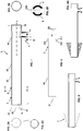
- a delivery device of a substance in the form of aerosol is designated as a whole with 1.
- the device 1 comprises a main body constituted by an outer body 2 and an inner body 3 housed within the outer body. Both bodies 2 and 3 have a substantially oblong shape and they are arranged with their own prevailing development longitudinal axis substantially coincident with, or parallel to, a longitudinal axis L of the device 1.
- the bodies 2 and 3 have a substantially cylindrical overall geometry.
- the outer body 2 is hollow and formed by a side skirt 20 and by a front face 21 bearing a dispensing nozzle 53, the latter with preferably rounded delivery section.
- the dispensing nozzle 53 is defined by walls 530 having substantially frustoconical geometry, the nozzle being obtained at a smaller base of the truncated cone.
- the inner body 3 is defined by a side skirt 30 arranged within the skirt 20 of the outer body 2 in slightly eccentric position with respect thereto with respect to the longitudinal axis L.
- the inner body 3 has then a front face 31 arranged substantially parallel to the front face 21 of the outer body 2 and spaced apart therefrom by means of one or more spacing elements 6.
- the spacing element 6, or each spacing element is manufactured in one piece or however made integral to the outer body 2.
- the inner body 3 has then a rear face 32 closing the device 1 on the rear side.
- the faces 21, 31 and 32 have substantially circular geometry.
- the inner body 3 at its own side skirt 30, bears an annular recess 310, defined in particular by a substantially cylindrical bottom wall 311 and by two side walls resulting plain in the side or longitudinal view of figures 1 and 3 .
- connection means 4 which in the present example are obtained integrally to the side skirt 20 of the outer body 2.
- connection means 4 comprises a coupling sleeve, designated too with 4, with substantially cylindrical geometry and arranged according to an axis T substantially orthogonal to the longitudinal axis L.
- the sleeve 4 bears an inner wall with section decreasing along the axis T, and in particular decreasing towards the side skirt 20 of the outer body 2.
- such decreasing section is obtained by means of a stepped inner profile 40.
- the sleeve 4 is arranged at the recess 310 of the inner body 3.
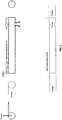
- the sleeve 4 is used for connecting the device 1 to a syringe 101, the latter meant to contain a substance in liquid form.
- a syringe 101 the latter meant to contain a substance in liquid form.
- such connection is of snap-in type, in particular a pressure snap-in, with the apex of the reservoir 102 of the syringe 101 received within the sleeve 4 itself.
- the sleeve 4 can bear a peripheral flange, or ring, 41 suitable to establish the tight and/or connection with specific types of syringe.
- the decentralized arrangement of the inner body 3 within the inner body 2 and the configuration of the device 1 described sofar makes that between outer body 2 and inner body 3 a fluidodynamic path 5 results to be defined, extending between the coupling sleeve 4 and the nozzle 53.
- Such path 5 is configured such that, in use, a manual actuation of the plunger 103 of the syringe 101 produces the input of the substance in liquid form from the reservoir 102 in the fluidodynamic path 5 through the coupling sleeve 4 and the outlet of the substance in the form of an aerosol (A) from the nozzle 53.
- the path 5 is configured so as to produce globally, between the coupling sleeve 4 and the dispensing nozzle 53, an increase in the flow velocity of the substance and a reduction of its flow rate.
- the fluidodynamic path 5 comprises a chamber 50 with substantially annular, preferably substantially toric, geometry defined between the recess 310 of the inner body 2 and the portion of the side skirt 20 of the outer body 2 facing on such recess 310.
- the annular chamber 50 by intervening downstream of the inner adduction channel defined by the sleeve 4, represents an expansion chamber for the fluid.
- the path 5 comprises a tract or chamber 52 with development substantially rectilinear along the longitudinal axis L, preferably arranged immediately downstream of the chamber 50.
- tract 52 is defined between the side skirts 20 and 30, substantially on the opposite side of the sleeve 4 and by virtue of the decentralized arrangement of the inner body 3 within the outer body 2.
- the longitudinal tract 52 defines a channel or chamber for accelerating the fluid, by virtue of the reduced cross section with respect to the chamber 50.
- the fluidodynamic path Downstream of such longitudinal tract 52, the fluidodynamic path provides then a cross portion 51, corresponding to the compartment defined between the two faces 21 and 31 and which ends in the nozzle 53.
- the fluid path from the expansion chamber 50 and through the acceleration channel 52 and the outlet orifice 53 makes that the fluid itself reaches a speed sufficient to the nebulization in the form of an aerosol.
- the syringe 101 can be replaced by any device bearing a container or reservoir of the substance in liquid form and manual actuation means apt to expel the substance from the container, the latter being constituted by a plunger or other.
- the overall delivery system constituted by the device 1 and by reservoir, syringe, container or other can provide that the substance received in the latter is in form different from liquid, for example partially aeriform or nebulized.
- the device and the system described herein can be integrated with a sealing element 7, preferably shaped like a truncated cone and for example made of plastic, gummy or spongy material ( figure 8A ) with the function of "sealing" the device 1, in particular at the orifice 53, at the nostril and/or to avoid too deep insertions, and the outlet, by gravity and absorption, of the drug.
- a sealing element 7 preferably shaped like a truncated cone and for example made of plastic, gummy or spongy material ( figure 8A ) with the function of "sealing" the device 1, in particular at the orifice 53, at the nostril and/or to avoid too deep insertions, and the outlet, by gravity and absorption, of the drug.
- the described delivery system can be provided in form of kit, in case even with reservoir or container with different capacity and, based upon an embodiment variant, in conjunction with one or more substances to be administered.
- the latter can be provided already received in the container, for example in the body of syringe, which for example can be equipped with tight seals removable upon use.
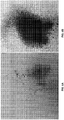
- Figures 6A and 6B show the results of preliminary delivery tests, wherein the better efficiency of the device 1 can be seen with respect to a known spray dispenser in terms of quantity and distribution of the substance.
- Figures 7A to 7D relate to preliminary delivery tests within the rhynosinusal cavities.
- the device of the considered variant is designated as a whole with 200.
- the device 200 comprises a main body constituted by an outer body 202 and by an inner body 203 housed within the outer body. Both bodies 202 and 203 have a substantially oblong shape and they are arranged with their own prevailing development longitudinal axis coincident with, or parallel to, a longitudinal axis L of the device 200.
- the inner body 203 has substantially cylindrical overall geometry.
- the outer body 202 bears a portion 222 with rounded profile.
- such portion 222 implements as a whole an ampulla-like shape.
- the portion 222 is interposed between two end portions of the outer body 202, respectively a distal portion 223 and a proximal portion 224 with respect to the user receiving the treatment.
- Such two distal 223 and proximal 224 portions have a restricted cross-section with respect to the rounded portion 222 and in particular a substantially cylindrical geometry.
- the outer body 202 is hollow and bears a front face 210, arranged at the proximal portion 224, having a dispensing nozzle 253 analogous to the one already described for the first embodiment.
- the outer body 202 bears a plurality of openings 226 to receive possible refluent fluid outgoing from the nostril. Through such openings 226, the refluent fluid is received in an inner container of the device 200.
- the container then can be emptied selectively by turning around the device, and then through the openings 226, or by allowing a removable connection of the portions 224 and 222 to the portion 223 of the outer body 202.
- the container can have a rounded and/or (almost) spherical shape, by following the profile of the portion 222, or oblong shape or with any other geometry.
- the container can be made at least partially by means of the walls of the portion 222 or be provided as a distinct component.
- the rounded portion 222 implements even a kind of "stop” which does not allow pushing the device 200, and in particular the portion 224, too much inside the nostril.
- connection means 204 substantially analogous to the already described ones.
- the device of the invention given the speed imparted to the fluid thanks to the toroidal expansion chamber ending in a path with very small diameter, can nebulize even viscous solutions constituted by macromolecules with sizes larger than 1000 kDa.
- the nebulization results to be constituted by particles which by more than 95% exceed 10 micron of diameter.
Landscapes
- Health & Medical Sciences (AREA)
- Engineering & Computer Science (AREA)
- General Health & Medical Sciences (AREA)
- Public Health (AREA)
- Anesthesiology (AREA)
- Biomedical Technology (AREA)
- Heart & Thoracic Surgery (AREA)
- Hematology (AREA)
- Life Sciences & Earth Sciences (AREA)
- Animal Behavior & Ethology (AREA)
- Veterinary Medicine (AREA)
- Pulmonology (AREA)
- Bioinformatics & Cheminformatics (AREA)
- Mechanical Engineering (AREA)
- Otolaryngology (AREA)
- Vascular Medicine (AREA)
- Chemical & Material Sciences (AREA)
- Dispersion Chemistry (AREA)
- Infusion, Injection, And Reservoir Apparatuses (AREA)
- Medicinal Preparation (AREA)
- Pharmaceuticals Containing Other Organic And Inorganic Compounds (AREA)
- Containers And Packaging Bodies Having A Special Means To Remove Contents (AREA)
Claims (14)
- Ausgabegerät (1) für eine Substanz in der Form eines Aerosols, das geeignet ist, um in Kombination mit einem Behälter (102) der Substanz in flüssiger Form verwendet zu werden, und mit manuellen Bedienungsmitteln (103), die geeignet sind, die Substanz aus dem Behälter (102) auszustoßen, insbesondere in Kombination mit einer Spritze (101),
wobei das Ausgabegerät (1) umfasst:- Verbindungsmittel (4), die geeignet sind, um das Gerät (1) mit dem Behälter (102) zu verbinden;- einen länglichen äußeren Körper (2), der eine Düse (53) zum Abgeben der Substanz in der Form eines Aerosols trägt;- einen inneren Körper (3), der in dem äußeren Körper (2) aufgenommen ist; und- einen fluid-dynamischen Pfad (5), der zwischen den Verbindungsmitteln (4) und der Abgabedüse (53) vorgesehen ist und zwischen dem äußeren Körper (2) und dem inneren Körper (3) definiert ist, wobei der Pfad (5) so konfiguriert ist, dass bei einer Anwendung eine manuelle Bedienung der Bedienungsmittel (103) eine Eingabe der Substanz in flüssiger Form in den fluid-dynamischen Pfad (5) durch die Verbindungsmittel (4) und den Auslass der Substanz in der Form eines Aerosols (53) durch die Abgabedüse (53) erzeugt,wobei der fluid-dynamische Pfad (5) umfasst▪ eine Expansionskammer (50), die unmittelbar stromabwärts von den Verbindungsmitteln (4) mit Bezug auf den Fluss der Substanz innerhalb der Vorrichtung (1) angeordnet ist und die eine im Wesentlich ringförmige Geometrie hat;▪ eine Beschleunigungskammer (52), die unmittelbar stromabwärts von der Expansionskammer (50) mit Bezug auf den Fluss der Substanz innerhalb der Vorrichtung (1) angeordnet ist und eine im Wesentlichen längliche Geometrie aufweist, wobei die Beschleunigungskammer (52) gemäß einer longitudinalen Richtung (L) im Wesentlichen parallel zu einer Achse der ringförmigen Expansionskammer (50) und/oder zu einer longitudinalen Achse (L) der Vorrichtung ausgebildet ist. - Vorrichtung (1) nach Anspruch 1, wobei der fluid-dynamische Pfad konfiguriert ist, so dass global zwischen den Verbindungsmitteln (4) und der Abgabedüse (53) eine Erhöhung der Fließgeschwindigkeit der Substanz und eine Verringerung ihrer Fließrate erzeugt wird.
- Vorrichtung (1) nach einem der vorhergehenden Ansprüche, wobei die Verbindungsmittel einen Verbindungskanal (4) aufweisen, der in einer Richtung im Wesentlichen senkrecht zu der longitudinalen Richtung (L) ausgebildet ist.
- Vorrichtung (1) nach einem der vorhergehenden Ansprüche, wobei die Abgabedüse (53) durch Wände definiert ist, die eine im Wesentlichen frustokonische Geometrie (530) darstellen, wobei die Düse (53) an einer kleineren Basis des Kegelstumpfes erhalten wird.
- Vorrichtung (1) nach einem der vorhergehenden Ansprüche, wobei die Verbindungsmittel ein Kupplungselement (4) umfassen, vorzugsweise in der Form eines Kragens, das geeignet ist, ein Einschnappende des Behälters (102) der Substanz in flüssiger Form aufzunehmen.
- Vorrichtung (1) nach einem der vorhergehenden Ansprüche, wobei die Verbindungsmittel (4) so konfiguriert sind, dass eine Verbindung mit dem Behälter (102) der Substanz in flüssiger Form gemäß einer Verbindungsrichtung (T) in Wesentlichen senkrecht zu einer longitudinalen Richtung (L) von der vorherrschenden Ausbildung der Vorrichtung (1) erlaubt wird.
- Vorrichtung (1) nach einem der vorhergehenden Ansprüche, wobei der äußere Körper (2) und/oder der innere Körper (3) eine im Wesentlichen längliche Form aufweisen, die vorzugsweise eine im Wesentlichen zylindrische Geometrie darstellt.
- Vorrichtung (1) nach einem der vorhergehenden Ansprüche, wobei der innere Körper (3) dezentriert mit Bezug auf den äußeren Körper (2) angeordnet ist, in solch einer Weise, dass zwischen ihnen eine Beschleunigungskammer (52) definiert bleibt.
- Vorrichtung (1) nach einem der vorhergehenden Ansprüche, die vom Einwegtyp ist.
- Vorrichtung (200) nach einem der vorhergehenden Ansprüche, wobei der äußere Körper (202) eine im Wesentlichen abgerundeten Abschnitt (222) umfasst, insbesondere geeignet, um als Begrenzung zum Beschränken der Penetration der Vorrichtung in ein Nasenloch zu wirken.
- Vorrichtung (200) nach einem der vorhergehenden Ansprüche, die einen Behälter aufweist, der angeordnet ist, um rückfließendes Fluid zu sammeln, das aus einem Nasenloch austritt.
- Vorrichtung (200) nach einem der vorhergehenden Ansprüche, wobei der äußere Körper (202) eine oder mehrere Öffnungen (226) zum Sammeln von rückfließendem Fluid trägt, das aus einem Nasenloch austritt.
- Gerät (100) zum Ausgeben einer Substanz in Form eines Aerosols, das eine Vorrichtung (1) gemäß einem der vorhergehenden Ansprüche, einen Behälter (102) der Substanz in flüssiger Form und manuelle Betätigungsmittel (103) umfasst, geeignet zum Ausstoßen der Substanz aus dem Behälter (102), wobei der Behälter (101) vorzugsweise ein Körper einer Nadel mit einem Stempel ist.
- System (100) nach einem der vorhergehenden Ansprüche, das in der Form eines Baukastens zur Verfügung gestellt wird.
Priority Applications (3)
| Application Number | Priority Date | Filing Date | Title |
|---|---|---|---|
| SM20170246T SMT201700246T1 (it) | 2013-10-11 | 2014-10-07 | Dispositivo per erogazione di una sostanza in forma di aerosol |
| HRP20170822TT HRP20170822T1 (hr) | 2013-10-11 | 2014-10-07 | Uređaj za davanje aeorosolne tvari |
| RS20170490A RS55971B1 (sr) | 2013-10-11 | 2014-10-07 | Uređaj za primenu aerosol supstance |
Applications Claiming Priority (2)
| Application Number | Priority Date | Filing Date | Title |
|---|---|---|---|
| ITRM20130562 ITRM20130562A1 (it) | 2013-10-11 | 2013-10-11 | Dispositivo di erogazione di una sostanza in forma di aerosol |
| PCT/IB2014/065121 WO2015052653A1 (en) | 2013-10-11 | 2014-10-07 | Device for delivery of an aerosol substance |
Publications (2)
| Publication Number | Publication Date |
|---|---|
| EP3055010A1 EP3055010A1 (de) | 2016-08-17 |
| EP3055010B1 true EP3055010B1 (de) | 2017-03-01 |
Family
ID=49683971
Family Applications (1)
| Application Number | Title | Priority Date | Filing Date |
|---|---|---|---|
| EP14798962.8A Active EP3055010B1 (de) | 2013-10-11 | 2014-10-07 | Vorrichtung zur verabreichung einer aerosolsubstanz |
Country Status (16)
| Country | Link |
|---|---|
| US (1) | US10493218B2 (de) |
| EP (1) | EP3055010B1 (de) |
| JP (1) | JP2016532535A (de) |
| KR (1) | KR20160070105A (de) |
| CN (1) | CN105636629B (de) |
| CA (1) | CA2926901A1 (de) |
| ES (1) | ES2626830T3 (de) |
| HK (1) | HK1223873A1 (de) |
| HR (1) | HRP20170822T1 (de) |
| IL (1) | IL245022B (de) |
| IT (1) | ITRM20130562A1 (de) |
| PT (1) | PT3055010T (de) |
| RS (1) | RS55971B1 (de) |
| RU (1) | RU2663493C2 (de) |
| SM (1) | SMT201700246T1 (de) |
| WO (1) | WO2015052653A1 (de) |
Families Citing this family (3)
| Publication number | Priority date | Publication date | Assignee | Title |
|---|---|---|---|---|
| US12226615B2 (en) * | 2017-11-10 | 2025-02-18 | Conzima Gmbh | Method and device for the needle-free injecting of fluid into a substrate |
| IT202000020791A1 (it) * | 2020-09-04 | 2022-03-04 | Daniele Scetta | Nebulizzazione ottenuta a partire da un erogatore mobile ancorato ad una siringa contenente una soluzione acquosa |
| CN113350634A (zh) * | 2021-07-16 | 2021-09-07 | 丁要武 | 喷雾给药装置和包括该装置的喷雾给药系统 |
Family Cites Families (28)
| Publication number | Priority date | Publication date | Assignee | Title |
|---|---|---|---|---|
| US1943092A (en) * | 1932-06-03 | 1934-01-09 | Lowell Mfg Company | Sprayer |
| FR1322998A (fr) * | 1962-02-23 | 1963-04-05 | Perfectionnements aux dispositifs de production d'aérosols | |
| US3251556A (en) * | 1963-12-26 | 1966-05-17 | Bete Fog Nozzle Inc | Humidifier nozzle |
| US3961756A (en) * | 1975-02-10 | 1976-06-08 | National Chemsearch Corporation | Adjustable-spray mechanism |
| NL180634C (nl) * | 1977-12-23 | 1987-04-01 | Duphar Int Res | Injectiespuit alsmede naaldhouder hiervoor. |
| DE7916475U1 (de) * | 1979-06-08 | 1979-10-18 | Hoechst Ag, 6000 Frankfurt | Spriihapplikator |
| JPS58156548U (ja) * | 1982-04-08 | 1983-10-19 | 株式会社共立合金製作所 | 気液混合噴霧用ノズル装置 |
| DE3315334A1 (de) * | 1983-04-28 | 1984-10-31 | Pfeiffer Erich Gmbh & Co Kg | Zerstaeuber- oder dosierpumpe |
| US4708292A (en) * | 1985-06-05 | 1987-11-24 | Olin Corporation | Foam dispensing gun with improved mixing chamber |
| DE4008069A1 (de) * | 1990-03-14 | 1991-09-19 | Pfeiffer Erich Gmbh & Co Kg | Austragkopf fuer medien |
| US5217442A (en) * | 1990-09-28 | 1993-06-08 | Minimed Technologies | Aspiration and refill kit for a medication infusion pump |
| IT1249600B (it) * | 1991-02-21 | 1995-03-09 | Elettro Plastica Spa | Erogatore nasale di sostanze farmaceutiche nebulizzate |
| GB9114080D0 (en) * | 1991-06-28 | 1991-08-14 | Weston Terence E | Atomising valve |
| GB2272389B (en) * | 1992-11-04 | 1996-07-24 | Bespak Plc | Dispensing apparatus |
| IT1266794B1 (it) * | 1993-11-09 | 1997-01-21 | Faustino Ballini | Dispositivo a doccia micronizzata per il lavaggio delle cavita' nasali e limitrofe |
| WO1997048496A1 (en) * | 1996-06-21 | 1997-12-24 | Hughes Technology Group L.L.C. | Micro-atomizing device |
| FR2784358B1 (fr) * | 1998-10-07 | 2000-12-29 | Sofab | Distributeur a mode de delivrance peripherique |
| GB0114272D0 (en) | 2001-06-12 | 2001-08-01 | Optinose As | Nasal delivery device |
| DK1092447T3 (da) * | 1999-10-14 | 2004-05-10 | Becton Dickinson Co | Nasalafgivelsesindretning indbefattende en spröjtedyse |
| EP2080561A3 (de) * | 2002-08-06 | 2016-11-16 | Glaxo Group Limited | Ausgabe |
| DE10239321B3 (de) * | 2002-08-27 | 2004-04-08 | Pari GmbH Spezialisten für effektive Inhalation | Aerosoltherapievorrichtung |
| CN2724849Y (zh) | 2004-07-16 | 2005-09-14 | 农业部南京农业机械化研究所 | 射流式空气混合喷嘴 |
| FI20055394A0 (fi) * | 2005-07-07 | 2005-07-07 | Metso Automation Oy | Paperirainan kostutussuutin |
| WO2007022898A2 (en) * | 2005-08-24 | 2007-03-01 | Boehringer Ingelheim International Gmbh | Atomiser comprising a counter and an end of operation lock |
| US8413651B2 (en) * | 2007-04-06 | 2013-04-09 | Becton, Dickinson And Company | Disposable spacer for inhalation delivery of aerosolized drugs and vaccines |
| GB0719299D0 (en) | 2007-10-03 | 2007-11-14 | Optinose As | Nasal delivery devices |
| NL2002787C2 (en) * | 2009-04-23 | 2010-10-26 | Medspray Xmems Bv | Atomising body, atomising device, inhaler, manufacturing method of manufacturing an atomising body and assembly method for assembling an atomising device. |
| GB0913699D0 (en) * | 2009-08-06 | 2009-09-16 | Mounteney Nicholas I | Scientific aerosol |
-
2013
- 2013-10-11 IT ITRM20130562 patent/ITRM20130562A1/it unknown
-
2014
- 2014-10-07 KR KR1020167012136A patent/KR20160070105A/ko not_active Ceased
- 2014-10-07 SM SM20170246T patent/SMT201700246T1/it unknown
- 2014-10-07 RU RU2016117992A patent/RU2663493C2/ru active
- 2014-10-07 ES ES14798962.8T patent/ES2626830T3/es active Active
- 2014-10-07 EP EP14798962.8A patent/EP3055010B1/de active Active
- 2014-10-07 CA CA2926901A patent/CA2926901A1/en not_active Abandoned
- 2014-10-07 PT PT147989628T patent/PT3055010T/pt unknown
- 2014-10-07 HK HK16112314.6A patent/HK1223873A1/zh unknown
- 2014-10-07 CN CN201480056047.8A patent/CN105636629B/zh active Active
- 2014-10-07 RS RS20170490A patent/RS55971B1/sr unknown
- 2014-10-07 JP JP2016547249A patent/JP2016532535A/ja active Pending
- 2014-10-07 HR HRP20170822TT patent/HRP20170822T1/hr unknown
- 2014-10-07 US US15/028,414 patent/US10493218B2/en active Active
- 2014-10-07 WO PCT/IB2014/065121 patent/WO2015052653A1/en not_active Ceased
-
2016
- 2016-04-10 IL IL245022A patent/IL245022B/en active IP Right Grant
Non-Patent Citations (1)
| Title |
|---|
| None * |
Also Published As
| Publication number | Publication date |
|---|---|
| US20160250423A1 (en) | 2016-09-01 |
| EP3055010A1 (de) | 2016-08-17 |
| RU2663493C2 (ru) | 2018-08-06 |
| PT3055010T (pt) | 2017-06-05 |
| RU2016117992A (ru) | 2017-11-16 |
| US10493218B2 (en) | 2019-12-03 |
| CN105636629A (zh) | 2016-06-01 |
| HK1223873A1 (zh) | 2017-08-11 |
| ITRM20130562A1 (it) | 2015-04-12 |
| CN105636629B (zh) | 2019-04-09 |
| KR20160070105A (ko) | 2016-06-17 |
| RS55971B1 (sr) | 2017-09-29 |
| SMT201700246T1 (it) | 2017-07-18 |
| RU2016117992A3 (de) | 2018-06-07 |
| IL245022A0 (en) | 2016-05-31 |
| WO2015052653A1 (en) | 2015-04-16 |
| CA2926901A1 (en) | 2015-04-16 |
| HRP20170822T1 (hr) | 2017-08-25 |
| IL245022B (en) | 2020-07-30 |
| ES2626830T3 (es) | 2017-07-26 |
| JP2016532535A (ja) | 2016-10-20 |
Similar Documents
| Publication | Publication Date | Title |
|---|---|---|
| US11975164B2 (en) | Nasal drug delivery device and method of making same | |
| ES2702981T3 (es) | Nebulizador nasal para irrigación y suministro de fármacos | |
| US20120017898A1 (en) | Method of administering a substance to the throat | |
| CN102223908A (zh) | 气雾吸入器 | |
| US20140283820A1 (en) | Method for Esophageal Drug Delivery | |
| JP2024523743A (ja) | 噴霧薬物投与装置及びそれを備える噴霧薬物投与システム | |
| US10493218B2 (en) | Device for delivery of an aerosol substance | |
| WO2021190369A1 (zh) | 鼻腔给药器、全组鼻窦给药器、鼻咽部给药器和给药方法 | |
| US20240366499A1 (en) | Topical preparations of drug delivery for nasal and sinus irrigation | |
| CN106345044A (zh) | 一种腔体雾化给药装置 | |
| CN105307713A (zh) | 用于吸入药用物质的元件 | |
| CN105816270A (zh) | 一种耳道给药器 | |
| CN203989334U (zh) | 一种雾化给药装置 | |
| ITBO20090132A1 (it) | Dispositivo per la nebulizzazione di sostanze in un circuito di ventilazione | |
| NL1043447B1 (en) | Spray Device | |
| JP2012029786A (ja) | 薬液吐出具 | |
| US20120065619A1 (en) | Method for labial, vaginal, transmucosal and transdermal metered dose dispensing | |
| CN103212145A (zh) | 药物雾化供药器 | |
| CN204092752U (zh) | 一种雾化口罩和雾化装置 | |
| CN209695991U (zh) | 一种利于加药雾化器 | |
| CN219231161U (zh) | 一种喷药器 | |
| CN215386924U (zh) | 鼻腔给药器 | |
| WO2026050768A1 (en) | Direction-tailored nasal-to-brain drug delivery system | |
| Khawaja et al. | Development and Patient Experience Evaluation of a Gentle Atomizer for Nasal Drug Delivery | |
| CN101920063A (zh) | 腔道黏膜给药器、给药装置和给药方法 |
Legal Events
| Date | Code | Title | Description |
|---|---|---|---|
| PUAI | Public reference made under article 153(3) epc to a published international application that has entered the european phase |
Free format text: ORIGINAL CODE: 0009012 |
|
| 17P | Request for examination filed |
Effective date: 20160419 |
|
| AK | Designated contracting states |
Kind code of ref document: A1 Designated state(s): AL AT BE BG CH CY CZ DE DK EE ES FI FR GB GR HR HU IE IS IT LI LT LU LV MC MK MT NL NO PL PT RO RS SE SI SK SM TR |
|
| AX | Request for extension of the european patent |
Extension state: BA ME |
|
| GRAP | Despatch of communication of intention to grant a patent |
Free format text: ORIGINAL CODE: EPIDOSNIGR1 |
|
| DAX | Request for extension of the european patent (deleted) | ||
| INTG | Intention to grant announced |
Effective date: 20160927 |
|
| GRAS | Grant fee paid |
Free format text: ORIGINAL CODE: EPIDOSNIGR3 |
|
| GRAA | (expected) grant |
Free format text: ORIGINAL CODE: 0009210 |
|
| AK | Designated contracting states |
Kind code of ref document: B1 Designated state(s): AL AT BE BG CH CY CZ DE DK EE ES FI FR GB GR HR HU IE IS IT LI LT LU LV MC MK MT NL NO PL PT RO RS SE SI SK SM TR |
|
| REG | Reference to a national code |
Ref country code: GB Ref legal event code: FG4D |
|
| REG | Reference to a national code |
Ref country code: CH Ref legal event code: EP Ref country code: AT Ref legal event code: REF Ref document number: 870554 Country of ref document: AT Kind code of ref document: T Effective date: 20170315 |
|
| REG | Reference to a national code |
Ref country code: IE Ref legal event code: FG4D |
|
| REG | Reference to a national code |
Ref country code: DE Ref legal event code: R096 Ref document number: 602014007244 Country of ref document: DE |
|
| REG | Reference to a national code |
Ref country code: NL Ref legal event code: FP |
|
| REG | Reference to a national code |
Ref country code: RO Ref legal event code: EPE |
|
| REG | Reference to a national code |
Ref country code: HR Ref legal event code: TUEP Ref document number: P20170822 Country of ref document: HR |
|
| REG | Reference to a national code |
Ref country code: CH Ref legal event code: NV Representative=s name: PATENTANWAELTE SCHAAD, BALASS, MENZL AND PARTN, CH |
|
| REG | Reference to a national code |
Ref country code: PT Ref legal event code: SC4A Ref document number: 3055010 Country of ref document: PT Date of ref document: 20170605 Kind code of ref document: T Free format text: AVAILABILITY OF NATIONAL TRANSLATION Effective date: 20170525 |
|
| REG | Reference to a national code |
Ref country code: LT Ref legal event code: MG4D |
|
| REG | Reference to a national code |
Ref country code: ES Ref legal event code: FG2A Ref document number: 2626830 Country of ref document: ES Kind code of ref document: T3 Effective date: 20170726 |
|
| PG25 | Lapsed in a contracting state [announced via postgrant information from national office to epo] |
Ref country code: FI Free format text: LAPSE BECAUSE OF FAILURE TO SUBMIT A TRANSLATION OF THE DESCRIPTION OR TO PAY THE FEE WITHIN THE PRESCRIBED TIME-LIMIT Effective date: 20170301 Ref country code: NO Free format text: LAPSE BECAUSE OF FAILURE TO SUBMIT A TRANSLATION OF THE DESCRIPTION OR TO PAY THE FEE WITHIN THE PRESCRIBED TIME-LIMIT Effective date: 20170601 Ref country code: LT Free format text: LAPSE BECAUSE OF FAILURE TO SUBMIT A TRANSLATION OF THE DESCRIPTION OR TO PAY THE FEE WITHIN THE PRESCRIBED TIME-LIMIT Effective date: 20170301 |
|
| REG | Reference to a national code |
Ref country code: HK Ref legal event code: DE Ref document number: 1223873 Country of ref document: HK |
|
| REG | Reference to a national code |
Ref country code: HR Ref legal event code: T1PR Ref document number: P20170822 Country of ref document: HR |
|
| PG25 | Lapsed in a contracting state [announced via postgrant information from national office to epo] |
Ref country code: SE Free format text: LAPSE BECAUSE OF FAILURE TO SUBMIT A TRANSLATION OF THE DESCRIPTION OR TO PAY THE FEE WITHIN THE PRESCRIBED TIME-LIMIT Effective date: 20170301 Ref country code: BG Free format text: LAPSE BECAUSE OF FAILURE TO SUBMIT A TRANSLATION OF THE DESCRIPTION OR TO PAY THE FEE WITHIN THE PRESCRIBED TIME-LIMIT Effective date: 20170601 Ref country code: LV Free format text: LAPSE BECAUSE OF FAILURE TO SUBMIT A TRANSLATION OF THE DESCRIPTION OR TO PAY THE FEE WITHIN THE PRESCRIBED TIME-LIMIT Effective date: 20170301 |
|
| REG | Reference to a national code |
Ref country code: FR Ref legal event code: PLFP Year of fee payment: 4 |
|
| PG25 | Lapsed in a contracting state [announced via postgrant information from national office to epo] |
Ref country code: EE Free format text: LAPSE BECAUSE OF FAILURE TO SUBMIT A TRANSLATION OF THE DESCRIPTION OR TO PAY THE FEE WITHIN THE PRESCRIBED TIME-LIMIT Effective date: 20170301 |
|
| REG | Reference to a national code |
Ref country code: GR Ref legal event code: EP Ref document number: 20170401435 Country of ref document: GR Effective date: 20171023 |
|
| PG25 | Lapsed in a contracting state [announced via postgrant information from national office to epo] |
Ref country code: PL Free format text: LAPSE BECAUSE OF FAILURE TO SUBMIT A TRANSLATION OF THE DESCRIPTION OR TO PAY THE FEE WITHIN THE PRESCRIBED TIME-LIMIT Effective date: 20170301 Ref country code: IS Free format text: LAPSE BECAUSE OF FAILURE TO SUBMIT A TRANSLATION OF THE DESCRIPTION OR TO PAY THE FEE WITHIN THE PRESCRIBED TIME-LIMIT Effective date: 20170701 |
|
| REG | Reference to a national code |
Ref country code: SK Ref legal event code: T3 Ref document number: E 24712 Country of ref document: SK Ref country code: DE Ref legal event code: R097 Ref document number: 602014007244 Country of ref document: DE |
|
| PLBE | No opposition filed within time limit |
Free format text: ORIGINAL CODE: 0009261 |
|
| STAA | Information on the status of an ep patent application or granted ep patent |
Free format text: STATUS: NO OPPOSITION FILED WITHIN TIME LIMIT |
|
| REG | Reference to a national code |
Ref country code: HK Ref legal event code: WD Ref document number: 1223873 Country of ref document: HK |
|
| PG25 | Lapsed in a contracting state [announced via postgrant information from national office to epo] |
Ref country code: DK Free format text: LAPSE BECAUSE OF FAILURE TO SUBMIT A TRANSLATION OF THE DESCRIPTION OR TO PAY THE FEE WITHIN THE PRESCRIBED TIME-LIMIT Effective date: 20170301 |
|
| 26N | No opposition filed |
Effective date: 20171204 |
|
| PG25 | Lapsed in a contracting state [announced via postgrant information from national office to epo] |
Ref country code: SI Free format text: LAPSE BECAUSE OF FAILURE TO SUBMIT A TRANSLATION OF THE DESCRIPTION OR TO PAY THE FEE WITHIN THE PRESCRIBED TIME-LIMIT Effective date: 20170301 |
|
| REG | Reference to a national code |
Ref country code: FR Ref legal event code: PLFP Year of fee payment: 5 |
|
| REG | Reference to a national code |
Ref country code: AT Ref legal event code: UEP Ref document number: 870554 Country of ref document: AT Kind code of ref document: T Effective date: 20170301 |
|
| PG25 | Lapsed in a contracting state [announced via postgrant information from national office to epo] |
Ref country code: HU Free format text: LAPSE BECAUSE OF FAILURE TO SUBMIT A TRANSLATION OF THE DESCRIPTION OR TO PAY THE FEE WITHIN THE PRESCRIBED TIME-LIMIT; INVALID AB INITIO Effective date: 20141007 |
|
| REG | Reference to a national code |
Ref country code: HR Ref legal event code: ODRP Ref document number: P20170822 Country of ref document: HR Payment date: 20191002 Year of fee payment: 6 |
|
| PG25 | Lapsed in a contracting state [announced via postgrant information from national office to epo] |
Ref country code: CY Free format text: LAPSE BECAUSE OF FAILURE TO SUBMIT A TRANSLATION OF THE DESCRIPTION OR TO PAY THE FEE WITHIN THE PRESCRIBED TIME-LIMIT Effective date: 20170301 |
|
| PG25 | Lapsed in a contracting state [announced via postgrant information from national office to epo] |
Ref country code: TR Free format text: LAPSE BECAUSE OF FAILURE TO SUBMIT A TRANSLATION OF THE DESCRIPTION OR TO PAY THE FEE WITHIN THE PRESCRIBED TIME-LIMIT Effective date: 20170301 |
|
| REG | Reference to a national code |
Ref country code: HR Ref legal event code: ODRP Ref document number: P20170822 Country of ref document: HR Payment date: 20200929 Year of fee payment: 7 |
|
| REG | Reference to a national code |
Ref country code: HR Ref legal event code: ODRP Ref document number: P20170822 Country of ref document: HR Payment date: 20210929 Year of fee payment: 8 |
|
| REG | Reference to a national code |
Ref country code: HR Ref legal event code: ODRP Ref document number: P20170822 Country of ref document: HR Payment date: 20220930 Year of fee payment: 9 |
|
| P01 | Opt-out of the competence of the unified patent court (upc) registered |
Effective date: 20230523 |
|
| REG | Reference to a national code |
Ref country code: HR Ref legal event code: ODRP Ref document number: P20170822 Country of ref document: HR Payment date: 20230928 Year of fee payment: 10 |
|
| REG | Reference to a national code |
Ref country code: HR Ref legal event code: ODRP Ref document number: P20170822 Country of ref document: HR Payment date: 20241003 Year of fee payment: 11 |
|
| PGFP | Annual fee paid to national office [announced via postgrant information from national office to epo] |
Ref country code: PT Payment date: 20250929 Year of fee payment: 12 |
|
| PGFP | Annual fee paid to national office [announced via postgrant information from national office to epo] |
Ref country code: RS Payment date: 20250930 Year of fee payment: 12 |
|
| REG | Reference to a national code |
Ref country code: HR Ref legal event code: ODRP Ref document number: P20170822 Country of ref document: HR Payment date: 20251003 Year of fee payment: 12 |
|
| REG | Reference to a national code |
Ref country code: CH Ref legal event code: U11 Free format text: ST27 STATUS EVENT CODE: U-0-0-U10-U11 (AS PROVIDED BY THE NATIONAL OFFICE) Effective date: 20251101 |
|
| PGFP | Annual fee paid to national office [announced via postgrant information from national office to epo] |
Ref country code: MK Payment date: 20240926 Year of fee payment: 11 |
|
| PGFP | Annual fee paid to national office [announced via postgrant information from national office to epo] |
Ref country code: LU Payment date: 20251022 Year of fee payment: 12 Ref country code: NL Payment date: 20251023 Year of fee payment: 12 |
|
| PGFP | Annual fee paid to national office [announced via postgrant information from national office to epo] |
Ref country code: DE Payment date: 20251020 Year of fee payment: 12 |
|
| PGFP | Annual fee paid to national office [announced via postgrant information from national office to epo] |
Ref country code: GB Payment date: 20251024 Year of fee payment: 12 |
|
| PGFP | Annual fee paid to national office [announced via postgrant information from national office to epo] |
Ref country code: MC Payment date: 20251022 Year of fee payment: 12 |
|
| PGFP | Annual fee paid to national office [announced via postgrant information from national office to epo] |
Ref country code: SM Payment date: 20251020 Year of fee payment: 12 Ref country code: AT Payment date: 20251021 Year of fee payment: 12 |
|
| PGFP | Annual fee paid to national office [announced via postgrant information from national office to epo] |
Ref country code: IT Payment date: 20251024 Year of fee payment: 12 |
|
| PGFP | Annual fee paid to national office [announced via postgrant information from national office to epo] |
Ref country code: HR Payment date: 20251003 Year of fee payment: 12 Ref country code: FR Payment date: 20251022 Year of fee payment: 12 |
|
| PGFP | Annual fee paid to national office [announced via postgrant information from national office to epo] |
Ref country code: BE Payment date: 20251022 Year of fee payment: 12 Ref country code: GR Payment date: 20251021 Year of fee payment: 12 Ref country code: AL Payment date: 20251014 Year of fee payment: 12 |
|
| PGFP | Annual fee paid to national office [announced via postgrant information from national office to epo] |
Ref country code: CH Payment date: 20251101 Year of fee payment: 12 |
|
| PGFP | Annual fee paid to national office [announced via postgrant information from national office to epo] |
Ref country code: CZ Payment date: 20251001 Year of fee payment: 12 Ref country code: IE Payment date: 20251021 Year of fee payment: 12 |
|
| PGFP | Annual fee paid to national office [announced via postgrant information from national office to epo] |
Ref country code: MT Payment date: 20251021 Year of fee payment: 12 |
|
| PGFP | Annual fee paid to national office [announced via postgrant information from national office to epo] |
Ref country code: SK Payment date: 20251003 Year of fee payment: 12 Ref country code: RO Payment date: 20251003 Year of fee payment: 12 |
|
| PGFP | Annual fee paid to national office [announced via postgrant information from national office to epo] |
Ref country code: ES Payment date: 20251114 Year of fee payment: 12 |