EP3055120B1 - Verfahren und vorrichtung zum herstellen eines mit füllgut gefüllten behälters - Google Patents
Verfahren und vorrichtung zum herstellen eines mit füllgut gefüllten behälters Download PDFInfo
- Publication number
- EP3055120B1 EP3055120B1 EP15712525.3A EP15712525A EP3055120B1 EP 3055120 B1 EP3055120 B1 EP 3055120B1 EP 15712525 A EP15712525 A EP 15712525A EP 3055120 B1 EP3055120 B1 EP 3055120B1
- Authority
- EP
- European Patent Office
- Prior art keywords
- preform
- blowing
- container
- feed line
- inner cavity
- Prior art date
- Legal status (The legal status is an assumption and is not a legal conclusion. Google has not performed a legal analysis and makes no representation as to the accuracy of the status listed.)
- Active
Links
Images



Classifications
-
- B—PERFORMING OPERATIONS; TRANSPORTING
- B29—WORKING OF PLASTICS; WORKING OF SUBSTANCES IN A PLASTIC STATE IN GENERAL
- B29C—SHAPING OR JOINING OF PLASTICS; SHAPING OF MATERIAL IN A PLASTIC STATE, NOT OTHERWISE PROVIDED FOR; AFTER-TREATMENT OF THE SHAPED PRODUCTS, e.g. REPAIRING
- B29C49/00—Blow-moulding, i.e. blowing a preform or parison to a desired shape within a mould; Apparatus therefor
- B29C49/42—Component parts, details or accessories; Auxiliary operations
- B29C49/46—Component parts, details or accessories; Auxiliary operations characterised by using particular environment or blow fluids other than air
-
- B—PERFORMING OPERATIONS; TRANSPORTING
- B29—WORKING OF PLASTICS; WORKING OF SUBSTANCES IN A PLASTIC STATE IN GENERAL
- B29C—SHAPING OR JOINING OF PLASTICS; SHAPING OF MATERIAL IN A PLASTIC STATE, NOT OTHERWISE PROVIDED FOR; AFTER-TREATMENT OF THE SHAPED PRODUCTS, e.g. REPAIRING
- B29C49/00—Blow-moulding, i.e. blowing a preform or parison to a desired shape within a mould; Apparatus therefor
- B29C49/08—Biaxial stretching during blow-moulding
- B29C49/10—Biaxial stretching during blow-moulding using mechanical means for prestretching
- B29C49/122—Drive means therefor
- B29C49/1229—Drive means therefor being a cam mechanism
-
- B—PERFORMING OPERATIONS; TRANSPORTING
- B29—WORKING OF PLASTICS; WORKING OF SUBSTANCES IN A PLASTIC STATE IN GENERAL
- B29C—SHAPING OR JOINING OF PLASTICS; SHAPING OF MATERIAL IN A PLASTIC STATE, NOT OTHERWISE PROVIDED FOR; AFTER-TREATMENT OF THE SHAPED PRODUCTS, e.g. REPAIRING
- B29C49/00—Blow-moulding, i.e. blowing a preform or parison to a desired shape within a mould; Apparatus therefor
- B29C49/28—Blow-moulding apparatus
- B29C49/30—Blow-moulding apparatus having movable moulds or mould parts
- B29C49/36—Blow-moulding apparatus having movable moulds or mould parts rotatable about one axis
-
- B—PERFORMING OPERATIONS; TRANSPORTING
- B29—WORKING OF PLASTICS; WORKING OF SUBSTANCES IN A PLASTIC STATE IN GENERAL
- B29C—SHAPING OR JOINING OF PLASTICS; SHAPING OF MATERIAL IN A PLASTIC STATE, NOT OTHERWISE PROVIDED FOR; AFTER-TREATMENT OF THE SHAPED PRODUCTS, e.g. REPAIRING
- B29C49/00—Blow-moulding, i.e. blowing a preform or parison to a desired shape within a mould; Apparatus therefor
- B29C49/42—Component parts, details or accessories; Auxiliary operations
- B29C49/64—Heating or cooling preforms, parisons or blown articles
- B29C49/6409—Thermal conditioning of preforms
-
- B—PERFORMING OPERATIONS; TRANSPORTING
- B65—CONVEYING; PACKING; STORING; HANDLING THIN OR FILAMENTARY MATERIAL
- B65B—MACHINES, APPARATUS OR DEVICES FOR, OR METHODS OF, PACKAGING ARTICLES OR MATERIALS; UNPACKING
- B65B3/00—Packaging plastic material, semiliquids, liquids or mixed solids and liquids, in individual containers or receptacles, e.g. bags, sacks, boxes, cartons, cans, or jars
- B65B3/02—Machines characterised by the incorporation of means for making the containers or receptacles
- B65B3/022—Making containers by moulding of a thermoplastic material
-
- B—PERFORMING OPERATIONS; TRANSPORTING
- B29—WORKING OF PLASTICS; WORKING OF SUBSTANCES IN A PLASTIC STATE IN GENERAL
- B29C—SHAPING OR JOINING OF PLASTICS; SHAPING OF MATERIAL IN A PLASTIC STATE, NOT OTHERWISE PROVIDED FOR; AFTER-TREATMENT OF THE SHAPED PRODUCTS, e.g. REPAIRING
- B29C49/00—Blow-moulding, i.e. blowing a preform or parison to a desired shape within a mould; Apparatus therefor
- B29C49/42—Component parts, details or accessories; Auxiliary operations
- B29C49/46—Component parts, details or accessories; Auxiliary operations characterised by using particular environment or blow fluids other than air
- B29C2049/4602—Blowing fluids
- B29C2049/4626—Blowing fluids containing carbon dioxide
-
- B—PERFORMING OPERATIONS; TRANSPORTING
- B29—WORKING OF PLASTICS; WORKING OF SUBSTANCES IN A PLASTIC STATE IN GENERAL
- B29C—SHAPING OR JOINING OF PLASTICS; SHAPING OF MATERIAL IN A PLASTIC STATE, NOT OTHERWISE PROVIDED FOR; AFTER-TREATMENT OF THE SHAPED PRODUCTS, e.g. REPAIRING
- B29C49/00—Blow-moulding, i.e. blowing a preform or parison to a desired shape within a mould; Apparatus therefor
- B29C49/42—Component parts, details or accessories; Auxiliary operations
- B29C49/46—Component parts, details or accessories; Auxiliary operations characterised by using particular environment or blow fluids other than air
- B29C2049/4602—Blowing fluids
- B29C2049/465—Blowing fluids being incompressible
-
- B—PERFORMING OPERATIONS; TRANSPORTING
- B29—WORKING OF PLASTICS; WORKING OF SUBSTANCES IN A PLASTIC STATE IN GENERAL
- B29C—SHAPING OR JOINING OF PLASTICS; SHAPING OF MATERIAL IN A PLASTIC STATE, NOT OTHERWISE PROVIDED FOR; AFTER-TREATMENT OF THE SHAPED PRODUCTS, e.g. REPAIRING
- B29C49/00—Blow-moulding, i.e. blowing a preform or parison to a desired shape within a mould; Apparatus therefor
- B29C49/42—Component parts, details or accessories; Auxiliary operations
- B29C49/78—Measuring, controlling or regulating
- B29C49/783—Measuring, controlling or regulating blowing pressure
- B29C2049/7831—Measuring, controlling or regulating blowing pressure characterised by pressure values or ranges
-
- B—PERFORMING OPERATIONS; TRANSPORTING
- B29—WORKING OF PLASTICS; WORKING OF SUBSTANCES IN A PLASTIC STATE IN GENERAL
- B29C—SHAPING OR JOINING OF PLASTICS; SHAPING OF MATERIAL IN A PLASTIC STATE, NOT OTHERWISE PROVIDED FOR; AFTER-TREATMENT OF THE SHAPED PRODUCTS, e.g. REPAIRING
- B29C49/00—Blow-moulding, i.e. blowing a preform or parison to a desired shape within a mould; Apparatus therefor
- B29C49/42—Component parts, details or accessories; Auxiliary operations
- B29C49/78—Measuring, controlling or regulating
- B29C49/783—Measuring, controlling or regulating blowing pressure
- B29C2049/7832—Blowing with two or more pressure levels
-
- B—PERFORMING OPERATIONS; TRANSPORTING
- B29—WORKING OF PLASTICS; WORKING OF SUBSTANCES IN A PLASTIC STATE IN GENERAL
- B29C—SHAPING OR JOINING OF PLASTICS; SHAPING OF MATERIAL IN A PLASTIC STATE, NOT OTHERWISE PROVIDED FOR; AFTER-TREATMENT OF THE SHAPED PRODUCTS, e.g. REPAIRING
- B29C2949/00—Indexing scheme relating to blow-moulding
- B29C2949/07—Preforms or parisons characterised by their configuration
- B29C2949/0715—Preforms or parisons characterised by their configuration the preform having one end closed
-
- B—PERFORMING OPERATIONS; TRANSPORTING
- B29—WORKING OF PLASTICS; WORKING OF SUBSTANCES IN A PLASTIC STATE IN GENERAL
- B29C—SHAPING OR JOINING OF PLASTICS; SHAPING OF MATERIAL IN A PLASTIC STATE, NOT OTHERWISE PROVIDED FOR; AFTER-TREATMENT OF THE SHAPED PRODUCTS, e.g. REPAIRING
- B29C49/00—Blow-moulding, i.e. blowing a preform or parison to a desired shape within a mould; Apparatus therefor
- B29C49/02—Combined blow-moulding and manufacture of the preform or the parison
- B29C49/06—Injection blow-moulding
-
- B—PERFORMING OPERATIONS; TRANSPORTING
- B29—WORKING OF PLASTICS; WORKING OF SUBSTANCES IN A PLASTIC STATE IN GENERAL
- B29C—SHAPING OR JOINING OF PLASTICS; SHAPING OF MATERIAL IN A PLASTIC STATE, NOT OTHERWISE PROVIDED FOR; AFTER-TREATMENT OF THE SHAPED PRODUCTS, e.g. REPAIRING
- B29C49/00—Blow-moulding, i.e. blowing a preform or parison to a desired shape within a mould; Apparatus therefor
- B29C49/08—Biaxial stretching during blow-moulding
- B29C49/10—Biaxial stretching during blow-moulding using mechanical means for prestretching
- B29C49/12—Stretching rods
- B29C49/121—Stretching rod configuration, e.g. geometry; Stretching rod material
- B29C49/1212—Stretching rod configuration, e.g. geometry; Stretching rod material the stretching rod comprising at least one opening on the surface, e.g. through which compressed air is blown into the preform to expand the same
-
- B—PERFORMING OPERATIONS; TRANSPORTING
- B29—WORKING OF PLASTICS; WORKING OF SUBSTANCES IN A PLASTIC STATE IN GENERAL
- B29C—SHAPING OR JOINING OF PLASTICS; SHAPING OF MATERIAL IN A PLASTIC STATE, NOT OTHERWISE PROVIDED FOR; AFTER-TREATMENT OF THE SHAPED PRODUCTS, e.g. REPAIRING
- B29C49/00—Blow-moulding, i.e. blowing a preform or parison to a desired shape within a mould; Apparatus therefor
- B29C49/08—Biaxial stretching during blow-moulding
- B29C49/10—Biaxial stretching during blow-moulding using mechanical means for prestretching
- B29C49/122—Drive means therefor
- B29C49/1222—Pneumatic
-
- B—PERFORMING OPERATIONS; TRANSPORTING
- B29—WORKING OF PLASTICS; WORKING OF SUBSTANCES IN A PLASTIC STATE IN GENERAL
- B29K—INDEXING SCHEME ASSOCIATED WITH SUBCLASSES B29B, B29C OR B29D, RELATING TO MOULDING MATERIALS OR TO MATERIALS FOR MOULDS, REINFORCEMENTS, FILLERS OR PREFORMED PARTS, e.g. INSERTS
- B29K2067/00—Use of polyesters or derivatives thereof, as moulding material
- B29K2067/003—PET, i.e. poylethylene terephthalate
-
- B—PERFORMING OPERATIONS; TRANSPORTING
- B29—WORKING OF PLASTICS; WORKING OF SUBSTANCES IN A PLASTIC STATE IN GENERAL
- B29L—INDEXING SCHEME ASSOCIATED WITH SUBCLASS B29C, RELATING TO PARTICULAR ARTICLES
- B29L2031/00—Other particular articles
- B29L2031/712—Containers; Packaging elements or accessories, Packages
- B29L2031/7158—Bottles
Definitions
- the invention relates to a method for producing a container filled with a liquid product, wherein a preform made of a thermoplastic material is stretched after a thermal conditioning by means of a stretching rod and formed in an inflation process in the container, wherein the inflation process comprises a Vorblasphase, in the a fluid of a first pressure level is used for inflation, and a main inflation phase in which a fluid of a second pressure level higher than the first pressure level is used for inflation.
- the invention further relates to a device for producing a container filled with a liquid product comprising a heating device for the thermal conditioning of preforms made of a thermoplastic material, and comprising a blowing device for forming each of a thermally conditioned preform in a container, wherein the blowing device is a blow mold for receiving a preform, a stretching rod for stretching the preform being blown, and feeding means for introducing blowing fluids into an internal cavity of the preform being in the blow mold.
- thermoplastic material such as preforms made of PET (polyethylene terephthalate)
- a blow molding machine has a heating device and a blowing device, in the region of which the previously tempered preform is expanded by biaxial orientation to form a container.
- the expansion takes place with the aid of compressed air, which is introduced into the preform to be expanded.
- compressed air which is introduced into the preform to be expanded.
- the procedural sequence in such an expansion of the preform is in the DE-OS 43 40 291 explained.
- the introductory mentioned introduction of the pressurized air also includes the introduction of compressed air into the developing container bubble and the compressed air introduction into the preform at the beginning of the blowing process.
- blowing process has proven to be advantageous to divide the blowing process into several phases. For example, it is known to subdivide the blowing process into a pre-blowing phase with a lower pressure level of the compressed air and into a main blowing phase with a higher pressure level of the compressed air.
- the blow-molded containers produced as above are fed to a subsequent filling device and filled here with the intended product.
- a separate blowing machine and a separate filling machine are thus used. It is also already known to directly couple a separate blowing machine and a separate filling machine and to provide a so-called blocked blow-filling device.
- An alternative known approach is based on making the shaping of the container by the product to be filled.
- a correspondingly tempered preform is used for this purpose in a suitable form and then the liquid product is introduced into the preform and in the resulting from this preform container bubble.
- the container bladder is in this case expanded until a complete contact with the inner contour of the mold is achieved and the container is filled.
- Such a process is also referred to as a hydraulic molding process.
- a container molding by the filling medium itself only only one machine is needed, but for a has increased complexity.
- it is difficult to provide controlled and reproducible conditions, particularly because the preform surface cools on contact with the liquid. Accordingly, it has not been satisfactorily successful to achieve any desired material distribution in the walls of the finished container.
- An essential advantage of the invention is that the Vorblasphase is carried out with a blowing gas, so that hardly takes place cooling of the preform material in contact with the blowing fluid.
- Another advantage of the invention is that the pre-blowing phase is based on well-understood processes and many years of experience.
- Another advantage of the invention is that in the main blowing phase, a rapid cooling of the container is achieved by the liquid product, which in comparison to conventional blow molding, in which the cooling is carried out by pressing the container to the cold blow mold, a much more efficient cooling and This achieves a shortening of the main blowing phase. It also eliminates transfer time to a separate filler and the filling time.
- Another advantage of the invention is that only for the Vorblasphase a compressed gas supply with medium pressures is required while the constructive consuming and therefore expensive supply of high-pressure air, as required in conventional gas-blowing processes, is eliminated.
- the blown gas is introduced, for example, through a gap in the region of a mouth portion of the preform or the developing container bubble and / or an inner cavity of the stretch rod in an inner cavity of the preform or the developing container bubble.
- This gap is, for example, an annular gap surrounding the stretching rod or a planar gap which results when the stretching rod is retracted in the region of the mouth section of the preform or of the developing container bladder or of the finished container.
- the mouth section is in particular the area of a preform which is not deformed during container production. More specifically, the mouth portion of the preform thus corresponds to the mouth portion of the container bladder developing from the preform and the mouth portion of the finished container obtained from the container bladder.
- the filling material is introduced, for example, through a gap in the region of an opening section of the preform or of the developing container bladder and / or an inner cavity of the stretching rod into an inner cavity of the preform or the developing container bladder.
- blown gas and filling material are introduced via separate introduction paths, for example blowing gas via the gap and filling material via the hollow stretching rod or vice versa, advantageously no lines or line sections are required which are alternately flowed through by both fluids.
- At least part of the blowing gas supplied during the pre-blowing phase remains in the container until the completion of the main blowing phase.
- the blowing gas is further compressed because the filling material is provided according to the invention under a higher pressure.
- the cycle time is minimized by the fate of blowing gas until complete formation of the container, because the main blowing phase can connect directly to the Vorblasphase without intermediate pressure relief of the developing container bubble.
- Another advantage is that the container has a gas-filled head space and so the leakage of filling material is reduced in the further handling of the finished, filled container.
- blowing gas contains a predeterminable proportion of carbon dioxide.
- CO 2 carbon dioxide
- the carbonization, in particular the amount of dissolved CO 2 in the filling is influenced via the predeterminable portion of the CO 2 in the blowing gas, with a higher proportion of CO 2 in the blowing gas also has a higher degree of carbonization result.
- the container is closed after completion of the main blowing phase, wherein the container is taken out of the blow mold in particular closed.
- a device for producing a container filled with a liquid product comprising a heating device for the thermal conditioning of preforms made of a thermoplastic material and comprising a blowing device for forming in each case a thermally conditioned preform into a container, wherein the blowing device a blow mold for receiving a preform, a stretching rod for drawing the blow mold preform and feeding means for introducing blowing fluids into an internal cavity of the blow mold preform, wherein the means according to the invention is further developed in that the feeding means is a first Supply line, which is designed for supplying a gas, and a second supply line, which is designed for supplying a liquid comprises.
- the device according to the invention is particularly suitable and arranged to carry out a previously described method according to the invention.
- the blowing device comprises a blowing nozzle for sealing a preform located in the blow mold, in particular for sealing an inner cavity of the preform, wherein by means of the blowing nozzle, the inner cavity of the preform with the first supply line and / or the second supply line is connected or connected flow-conducting.
- the tuyere is placed on the mouth region of a preform located in the blow mold.
- the tuyere preferably engages the transport mandrel, wherein the transport mandrel has a channel for supplying the fluid provided by the tuyere into the preform or the developing container bladder.
- the stretch rod is hollow, wherein by means of the stretch rod, an inner cavity of a preform located in the blow mold with the first supply line and / or the second supply line is connected or connected in flow conduction.
- the device further comprises a changeover valve to which the input side and the first supply line and the second supply line and a third supply line are connected, wherein the third supply line both for supplying gases and for supplying Liquids is formed and wherein an inner cavity of a preform located in the blow mold, in particular by means of the blowing nozzle and / or by means of the hollow stretch rod, with the third supply line connected or connected in fluid flow.
- a changeover valve to which the input side and the first supply line and the second supply line and a third supply line are connected, wherein the third supply line both for supplying gases and for supplying Liquids is formed and wherein an inner cavity of a preform located in the blow mold, in particular by means of the blowing nozzle and / or by means of the hollow stretch rod, with the third supply line connected or connected in fluid flow.
- the device further comprises supply means connected in flow-conducting connection with the first supply line for providing a blown gas, the provisioning means being a mixing device for Providing a gas mixture of gases from at least two different gas sources.
- the device further comprises a closing device for closing a container filled with filling material, in particular for closing a container located in the blow mold.
- a device according to the invention can also have a plurality of, preferably similar, blowing devices, which are arranged, for example, on a rotating blowing wheel.
- blowing devices can also share individual features, for example a common supply lines for supplying gas and / or liquid to a plurality of blowing devices.
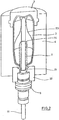
- FIG Fig. 1 The basic structure of a device according to the invention for producing a container (2) from a preform (1) filled with a liquid filling material is shown in FIG Fig. 1 and in Fig. 2 shown.
- the arrangement can be as shown or rotated in a vertical plane by 180 °.
- the device for producing the container (2) consists essentially of a blowing station (3) which is provided with a blow mold (4) into which a preform (1) can be inserted.
- the preform (1) may be an injection-molded part of polyethylene terephthalate.
- the blow mold (4) consists of mold halves (5, 6) and a bottom part (7), which is a lifting device (8) is positionable.
- the preform (1) can be held in the region of the blowing station (3) by a transport mandrel (9) which, together with the preform (1), passes through a plurality of treatment stations within the device. But it is also possible to use the preform (1), for example via pliers or other handling means directly into the blow mold (4).
- a connecting piston (10) is arranged, which feeds the preform (1) compressed air and at the same time makes a seal relative to the transport mandrel (9).
- a connecting piston (10) is arranged, which feeds the preform (1) compressed air and at the same time makes a seal relative to the transport mandrel (9).
- a stretching of the preform (1) takes place in this embodiment by means of a stretching rod (11), which is positioned by a cylinder (12).
- a mechanical positioning of the stretch rod (11) is carried out over curve segments, which are acted upon by Abgriff rollers.
- the use of curve segments is particularly useful when a plurality of blowing stations (3) are arranged on a rotating blowing wheel.
- the stretching system is designed such that a tandem arrangement of two cylinders (12) is provided. From a primary cylinder (13), the stretch rod (11) is first moved to the area of a bottom (14) of the preform (1) before the beginning of the actual stretching operation.
- the primary cylinder (13) is positioned with extended stretch rod together with a primary cylinder (13) carrying slide (15) by a secondary cylinder (16) or via a cam control.
- a current stretching position is predetermined by a guide roller (17) which slides along a curved path during the execution of the stretching operation.
- the guide roller (17) is pressed by the secondary cylinder (16) against the guideway.
- the carriage (15) slides along two guide elements (18).
- the carriers (19, 20) are locked relative to one another by means of a locking device (40).
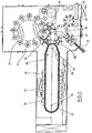
- Fig. 2 shows in addition to the blown container (2) and dashed lines drawn the preform (1) and schematically a developing container bladder (23).
- Fig. 3 shows the basic structure of a blow molding machine, which is provided with a heating section (24) and a rotating blowing wheel (25).
- a preform input (26) the preforms (1) are transported by transfer wheels (27, 28, 29) into the region of the heating path (24).
- Heater (30) and fan (31) are arranged along the heating path (24) in order to temper the preforms (1).
- After a sufficient temperature control of the preforms (1) they are transferred to the blowing wheel (25), in the region of which the blowing stations (3) are arranged.
- the finished blown containers (2) are fed by further transfer wheels to a delivery line (32).
- thermoplastic material different plastics can be used.
- PET polyethylene terephthalate
- PEN polyethylene naphthalate
- PP polypropylene
- the expansion of the preform (1) during the orientation process is carried out by fluid supply.
- the fluid supply is in a Vorblasphase in which gas, for example compressed air, is supplied at a low pressure level and subdivided into a subsequent Hauptblasphase in the liquid product, such as drinking water, is supplied at a higher pressure level.
- gas for example compressed air
- the pre-blowing phase compressed air is typically used at a pressure in the interval of 10 bar to 25 bar, the pre-blowing phase is already ended when the pressure in the developing container bubble has risen to 2 bar to 5 bar.
- the heating section (24) is formed of a plurality of revolving transport elements (33), which are lined up like a chain and guided along deflection wheels (34). In particular, it is thought to open up a substantially rectangular basic contour by the chain-like arrangement.
- a single relatively large-sized guide wheel (34) and in the region of adjacent deflections two comparatively smaller dimensioned guide wheels (36) used , In principle, however, any other guides are conceivable.
- the arrangement shown to be particularly useful since in the region of the corresponding extent of the heating section (24) three deflecting wheels (34, 36) are positioned, and although in each case the smaller deflection wheels (36) in the region of the transition to the linear curves of the heating section (24) and the larger deflection wheel (34) in the immediate transfer area to the transfer wheel (29) and the input wheel (35).
- chain-like transport elements (33) it is also possible, for example, to use a rotating heating wheel.
- modified heating section (24) can be tempered by the larger number of radiant heaters (30) a larger amount of preforms (1) per unit time.
- the fans (31) introduce cooling air into the region of cooling air ducts (39), which in each case oppose the associated radiant heaters (30) and emit the cooling air via outflow openings. By arranging the outflow directions, a flow direction for the cooling air is realized substantially transversely to a transport direction of the preforms (1).
- the cooling air ducts (39) can provide reflectors for the heating radiation in the area opposite the radiant heaters (30), and it is likewise possible to realize cooling of the radiant heaters (30) via the discharged cooling air.
- a transport of the preforms (1) and the container (2) by the blow molding machine can be done in different ways.
- the preforms (1) are carried by transport spikes at least along the essential part of their transport path.
- different variants are conceivable with regard to the spatial orientation of the preforms (1).
- the preform (1) in the region of the preform input (26) is fed with its mouth oriented vertically upwards, then rotated along the heating path (24) and the blowing wheel (25) with its mouth in the vertical direction downwards conveyed oriented and rotated again as a blown and filled container (2) before reaching the output path (32).
- Corresponding transport means for example transport mandrels, have corresponding sealing devices in order to ensure that the product introduced during the blowing process remains in the container (2).
- the preform (1) in the region of the heating section (24) with its mouth in the vertical direction is heated oriented downwards, but rotated again by 180 ° before reaching the blowing wheel (25).
- the preform (1) or the container (2) passes through the entire area of the blow molding machine with its mouth oriented in a vertical direction without performing turning operations.
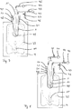
- Fig. 5 shows a blow mold (4), in which a preform (1) is located.
- the preform (1) is arranged, for example, with its mouth section (21) pointing upwards in the blow mold (4).
- a connecting piston (10) which is also referred to as a blowing nozzle, arranged, which seals the preform (1) by means of a seal (48).
- the blowing nozzle (10) defines a gap (41) through which blowing fluids are introduced into the preform (1). Through the gap (41) through a stretch rod (11) is guided, so that the gap (41) in response to the position of the stretch rod (11) assumes a circular or an annular cross-section.
- a compressed air guide is connected or connectable, which comprises a compressed air source (42) and a compressed air valve (43).
- a compressed air source (42)
- a compressed air valve 43
- the preform (1) is longitudinally axial, i.e., longitudinal, by means of the stretching rod (11) which bears against a dome of the preform (1). along a longitudinal axis of the preform (1), stretched.
- a container bladder (23) develops, which, for example, already partly abuts the blow mold (4) at the end of the preblow phase.
- the container bladder (23) is exemplified as a dashed line in FIG Fig. 5 shown.
- Vorblasphase subsequent main blowing liquid contents such as drinking water, from a Gear train (44) under pressure and controlled by a Gearventil (45), introduced into the container bladder (23).
- the pressure of the provided contents is greater than the internal pressure in the container bladder (23), so that the container bladder (23) is further expanded until it rests everywhere on the blow mold (4).
- the pressure within the container bladder (23) continues to increase, wherein the pressure increase can be influenced, for example, by targeted control of an exhaust valve (47) and corresponding discharge of a portion of the blast gas from the container bladder (23) via an exhaust (46).
- the main blowing phase can also be done without discharging blowing gas, for example to achieve the fastest possible increase in pressure within the container bladder (23).
- valves (43, 45, 47) are expressly to be understood as exemplary.
- Alternative solutions are expressly included in the invention.
- the container (2) After forming the container bladder (23), the container (2) is completed and can be removed after pressure relief via the Exhaust (46) as a filled container of the blow mold (4).
- the container (2) is closed before removal, for example, to avoid leakage or spilling out of contents from the container (2) during removal.
- the stretch rod (11) is hollow and has a plurality of outlet openings (49) which open in the lower region of the stretch rod (11) in the preform (1). This makes it possible to introduce the blowing fluids via the stretch rod (11) in the preform (1).
- FIG. 7 Another variant of the invention is in Fig. 7 shown.
- This variant is different from the one in Fig. 6 illustrated variant mainly in that the blowing gas via the blowing nozzle (10) and the contents via the hollow stretching rod (11) is supplied.
- the hollow stretch rod (11) has a single, downwardly directed to the container bottom outlet opening (49).
- This embodiment of the hollow stretch rod (11) is fluidically advantageous for incompressible fluids such as the contents, but it requires that the stretch rod (11) is at least slightly raised after completion of the stretching operation and before the start of the main blowing to allow outflow of the filling material ,
- the embodiments of the hollow stretch rod (11) shown are basically exemplary. In principle, a combination of lateral outflow openings (49) with a central outflow opening (49) on the stretching rod tip is also conceivable. In addition, any embodiments of a hollow stretching rod can be used both for introducing a blowing gas and for introducing a filling material within the scope of the invention.
- a fourth embodiment of the invention is in Fig. 8 represented, in which case the filling material is supplied or introduced both via the blowing nozzle (10) and via the hollow stretching rod (11).
- the cross section or line cross section available for introducing the filling material is increased, so that an increased volume flow for the filling material can be realized.
Landscapes
- Engineering & Computer Science (AREA)
- Mechanical Engineering (AREA)
- Manufacturing & Machinery (AREA)
- Physics & Mathematics (AREA)
- Thermal Sciences (AREA)
- Blow-Moulding Or Thermoforming Of Plastics Or The Like (AREA)
Description
- Die Erfindung betrifft ein Verfahren zum Herstellen eines mit einem flüssigen Füllgut gefüllten Behälters, bei dem ein Vorformling aus einem thermoplastischen Material nach einem thermischen Konditionieren mittels einer Reckstange gereckt und in einem Aufblasprozess in den Behälter umgeformt wird, wobei der Aufblasprozess umfasst eine Vorblasphase, in der ein Fluid eines ersten Druckniveaus zum Aufblasen verwendet wird, und eine Hauptblasphase, in der ein Fluid eines zweiten Druckniveaus, das höher ist als das erste Druckniveau, zum Aufblasen verwendet wird.
- Die Erfindung betrifft ferner eine Einrichtung zur Herstellung eines mit einem flüssigen Füllgut gefüllten Behälters umfassend eine Heizvorrichtung zur thermischen Konditionierung von Vorformlingen aus einem thermoplastischen Material, und umfassend eine Blasvorrichtung zum Umformen jeweils eines thermisch konditionierten Vorformlings in einen Behälter, wobei die Blasvorrichtung eine Blasform zur Aufnahme eines Vorformlings, eine Reckstange zum Recken des in der Blasform befindlichen Vorformlings sowie Zuführmittel zum Einleiten von Blasfluiden in einen inneren Hohlraum des in der Blasform befindlichen Vorformlings aufweist.
- Bei einer Behälterformung durch Blasdruckeinwirkung werden Vorformlinge aus einem thermoplastischen Material, beispielsweise Vorformlinge aus PET (Polyethylenterephthalat), innerhalb einer Blasmaschine unterschiedlichen Bearbeitungsstationen zugeführt. Typischerweise weist eine derartige Blasmaschine eine Heizeinrichtung sowie eine Blaseinrichtung auf, in deren Bereich der zuvor temperierte Vorformling durch biaxiale Orientierung zu einem Behälter expandiert wird.
- Die Expansion erfolgt mit Hilfe von Druckluft, die in den zu expandierenden Vorformling eingeleitet wird. Der verfahrenstechnische Ablauf bei einer derartigen Expansion des Vorformlings wird in der
DE-OS 43 40 291 - Als vorteilhaft hat es sich erwiesen, den Blasvorgang in mehrere Phasen zu unterteilen. Beispielsweise ist bekannt, den Blasvorgang in eine Vorblasphase mit einem niedrigeren Druckniveau der Druckluft und in eine Hauptblasphase mit einem höheren Druckniveau der Druckluft zu unterteilen.
- Der grundsätzliche Aufbau einer Blasstation zur Behälterformung wird in der
DE-OS 42 12 583 DE-OS 23 52 926 - Weitere bekannte Verfahren und Vorrichtungen zum Herstellen eines mit einem flüssigen Füllgut gefüllten Behälters sind in den Dokumenten
US2013/122136A1 ,US2013/113143A1 undUS2011/135778A1 beschrieben. - Gemäß einem typischen Verarbeitungsverfahren werden die wie vorstehend hergestellten blasgeformten Behälter einer nachfolgenden Fülleinrichtung zugeführt und hier mit dem vorgesehenen Produkt abgefüllt. In der Regel werden somit eine separate Blasmaschine und eine separate Füllmaschine verwendet. Bekannt ist es ebenfalls bereits, eine separate Blasmaschine und eine separate Füllmaschine unmittelbar miteinander zu koppeln und eine sogenannte verblockte Blas-Füll-Einrichtung bereitzustellen.
- Aufgrund der zwei separaten Maschinen ergeben sich für entsprechende Anlagen ein relativ großer Platzbedarf und eine relativ lange Prozesszeit, die sich zusammensetzt aus der Dauer des Blasprozesses, der Dauer des Füllprozesses sowie Transferzeiten zwischen den einzelnen bzw. verblockten Maschinen.
- Ein alternativer bekannter Ansatz beruht darauf, die Formung der Behälter durch das abzufüllende Produkt selbst vorzunehmen. Ein entsprechend temperierter Vorformling wird hierzu in eine geeignete Form eingesetzt und anschließend wird das flüssige Produkt in den Vorformling sowie in die sich aus diesem Vorformling entwickelnde Behälterblase eingeleitet. Die Behälterblase wird hierbei solange aufgeweitet, bis eine vollständige Anlage an der Innenkontur der Form erreicht und der Behälter gefüllt ist. Ein derartiges Verfahren wird auch als hydraulisches Formungsverfahren bezeichnet. Bei einer Behälterformung durch das Füllmedium selbst wird lediglich nur noch eine Maschine benötigt, die dafür allerdings eine erhöhte Komplexität aufweist. Außerdem ist es bei einem Blasprozess mit einer Flüssigkeit schwierig, kontrollierte und reproduzierbare Bedingungen zu schaffen, insbesondere weil die Vorformlingsoberfläche bei Kontakt mit der Flüssigkeit abkühlt. Entsprechend ist es bisher nicht zufriedenstellend gelungen, eine beliebige gewünschte Materialverteilung in den Wandungen der fertigen Behälter zu erreichen.
- Ausgehend von diesem Stand der Technik ist es eine Aufgabe der Erfindung, ein alternatives Verfahren zur Herstellung von mit flüssigem Füllgut gefüllten Behältern bereitzustellen, wobei insbesondere die genannten Nachteile bekannter Lösungen verringert werden sollen.
- Diese Aufgabe wird gelöst durch ein Verfahren nach Anspruch 1 und eine Vorrichtung nach Anspruch 5. Vorteilhafte Ausführungsformen und Weiterbildungen sind Gegenstand der Unteransprüche. Ein wesentlicher Vorteil der Erfindung besteht darin, dass die Vorblasphase mit einem Blasgas erfolgt, so dass kaum Abkühlung des Vorformlingsmaterials bei Kontakt mit dem Blasfluid erfolgt. Dadurch wird während der Vorblasphase eine gezielt beeinflussbare Materialverteilung des Vorformlingsmaterials, insbesondere entlang einer Längsachse des Vorformlings, die der Richtung des in der Vorblasphase umfassten Reckvorgangs entspricht, erreicht. Ein weiterer Vorteil der Erfindung ist es, dass die Vorblasphase auf sehr gut verstandenen Prozessen und langjähriger Erfahrung beruht.
- Ein weiterer Vorteil der Erfindung besteht darin, dass in der Hauptblasphase eine schnelle Abkühlung des Behälters durch das flüssige Füllgut erreicht wird, wodurch im Vergleich zu herkömmlichen Blasverfahren, bei denen die Abkühlung über Andrücken des Behälters an die kalte Blasform erfolgt, eine wesentlich effizientere Kühlung und dadurch eine Verkürzung der Hauptblasphase erreicht wird. Zudem entfallen Transferzeit zu einem separaten Füller und die Füllzeit.
- Ein weiterer Vorteil der Erfindung besteht darin, dass lediglich für die Vorblasphase eine Druckgasversorgung mit mittleren Drücken erforderlich ist, während die konstruktiv aufwendige und daher teure Versorgung mit Hochdruckluft, wie sie in herkömmlichen Gasblasprozessen erforderlich ist, entfällt.
- Insgesamt wird durch die Erfindung die Prozesszeit gegenüber Standardblasverfahren mit Blasgas und separatem Füllen wesentlich verkürzt, wobei gegenüber bekannten Flüssigblasverfahren eine wesentlich bessere Prozesskontrolle, insbesondere eine wesentlich verbesserte Materialverteilung, erreicht wird.
- Das Blasgas wird beispielsweise durch einen Spalt im Bereich eines Mündungsabschnitts des Vorformlings bzw. der sich entwickelnden Behälterblase und/oder einen inneren Hohlraum der Reckstange in einen inneren Hohlraum des Vorformlings bzw. der sich entwickelnden Behälterblase eingeleitet.
- Dieser Spalt ist beispielsweise ein die Reckstange umgebender Ringspalt oder ein flächiger Spalt, der sich bei Zurückziehen der Reckstange im Bereich des Mündungsabschnitts des Vorformlings bzw. der sich entwickelnden Behälterblase bzw. des fertigen Behälters ergibt.
- Der Mündungsabschnitt ist dabei insbesondere der Bereich eines Vorformlings, der bei der Behälterherstellung nicht verformt ist. Insbesondere entspricht der Mündungsabschnitt des Vorformlings somit dem Mündungsabschnitt der sich aus dem Vorformling entwickelnden Behälterblase und dem Mündungsabschnitt des aus der Behälterblase erhaltenen fertigen Behälters.
- Das Füllgut wird beispielsweise durch einen Spalt im Bereich eines Mündungsabschnitts des Vorformlings bzw. der sich entwickelnden Behälterblase und/oder einen inneren Hohlraum der Reckstange in einen inneren Hohlraum des Vorformlings bzw. der sich entwickelnden Behälterblase eingeleitet.
- Wenn Blasgas und Füllgut über getrennte Einleitwege, beispielsweise Blasgas über den Spalt und Füllgut über die hohle Reckstange oder umgekehrt, eingeleitet werden, bedarf es vorteilhafterweise keiner Leitungen oder Leitungsabschnitte, die wechselnd von beiden Fluiden durchströmt werden.
- Wenn ein Fluid über beide Einleitwege gleichzeitig eingeleitet wird, d.h. sowohl über den Spalt als auch über die hohle Reckstange, ergibt sich der besondere Vorteil eines erhöhten Strömungsquerschnitts und somit insbesondere im Falle des Füllgutes eines erhöhten maximal erreichbaren Volumenstroms.
- Vorteilhafterweise verbleibt wenigstens ein Teil des während der Vorblasphase zugeführten Blasgases bis zum Abschluss der Hauptblasphase im Behälter. Dabei wird das Blasgas weiter komprimiert, weil das Füllgut erfindungsgemäß unter einem höheren Druck bereitgestellt wird.
- Durch den Verbleib von Blasgas bis zur vollständigen Ausformung des Behälters wird insbesondere die Zykluszeit minimiert, weil sich die Hauptblasphase ohne zwischengeschaltete Druckentlastung der sich entwickelnden Behälterblase direkt an die Vorblasphase anschließen kann. Ein weiterer Vorteil besteht darin, dass der Behälter einen gasgefüllten Kopfraum aufweist und so das Auslaufen von Füllgut bei der weiteren Handhabung des fertigen, gefüllten Behälters reduziert wird.
- Eine vorteilhafte Weiterbildung der Erfindung ist dadurch gekennzeichnet, dass das Blasgas einen vorgebbaren Anteil an Kohlenstoffdioxid enthält. Dies führt in der Hauptblasphase zu einer Karbonisierung des Füllgutes, indem Kohlenstoffdioxid (CO2) aus dem Blasgas unter Druck im Füllgut gelöst wird. Der Karbonisierungsgrad, insbesondere die Menge an im Füllgut gelöstem CO2, ist dabei über den vorgebbaren Anteil des CO2 im Blasgas beeinflussbar, wobei ein höherer Anteil von CO2 im Blasgas auch einen höheren Karbonisierungsgrad zur Folge hat.
- Vorteilhafterweise wird der Behälter nach Abschluss der Hauptblasphase verschlossen, wobei der Behälter insbesondere erst verschlossen aus der Blasform entnommen wird. Dadurch wird die Handhabung des gefüllten Behälters, insbesondere die Entnahme aus der Blasform und die anschließende Abförderung, wesentlich vereinfacht, weil insbesondere keine bei der Handhabung offener Behälter stets möglichen Füllgutverluste auftreten können.
- Die der Erfindung zugrundeliegende Aufgabe wird ferner gelöst durch eine Einrichtung zur Herstellung eines mit einem flüssigen Füllgut gefüllten Behälters umfassend eine Heizvorrichtung zur thermischen Konditionierung von Vorformlingen aus einem thermoplastischen Material und umfassend eine Blasvorrichtung zum Umformen jeweils eines thermisch konditionierten Vorformlings in einen Behälter, wobei die Blasvorrichtung eine Blasform zur Aufnahme eines Vorformlings, eine Reckstange zum Recken des in der Blasform befindlichen Vorformlings sowie Zuführmittel zum Einleiten von Blasfluiden in einen inneren Hohlraum des in der Blasform befindlichen Vorformlings aufweist, wobei die erfindungsgemäße Einrichtung dadurch weitergebildet ist, dass die Zuführmittel eine erste Zuleitung, die ausgelegt ist zum Zuführen eines Gases, und eine zweite Zuleitung, die ausgelegt ist zum Zuführen einer Flüssigkeit, umfasst.
- Die erfindungsgemäße Einrichtung ist insbesondere dazu geeignet und eingerichtet, ein zuvor beschriebenes Verfahren gemäß der Erfindung auszuführen.
- Vorteilhafterweise umfasst die Blasvorrichtung eine Blasdüse zum Abdichten eines in der Blasform befindlichen Vorformlings, insbesondere zum Abdichten eines inneren Hohlraums des Vorformlings, wobei mittels der Blasdüse der innere Hohlraum des Vorformlings mit der ersten Zuleitung und/oder der zweiten Zuleitung strömungsleitend verbindbar oder verbunden ist.
- Hierzu wird beispielsweise die Blasdüse auf den Mündungsbereich eines in der Blasform befindlichen Vorformlings aufgesetzt. Für den Fall, dass der Vorformling mittels eines Transportdorns transportiert wird, so greift die Blasdüse vorzugsweise am Transportdorn an, wobei der Transportdorn über einen Kanal zum Zuleiten des mittels der Blasdüse bereitgestellten Fluids in den Vorformling bzw. die sich entwickelnde Behälterblase verfügt.
- Bei einer weiteren Ausführungsform der Erfindung ist die Reckstange hohl ausgebildet, wobei mittels der Reckstange ein innerer Hohlraum eines in der Blasform befindlichen Vorformlings mit der ersten Zuleitung und/oder der zweiten Zuleitung strömungsleitend verbindbar oder verbunden ist.
- Eine besonders bevorzugte Weiterbildung der Erfindung ist dadurch ausgezeichnet, dass die Einrichtung ferner umfasst ein Umschaltventil, an dass eingangsseitig die erste Zuleitung und die zweite Zuleitung sowie ausgangsseitig eine dritte Zuleitung angeschlossen sind, wobei die dritte Zuleitung sowohl zum Zuleiten von Gasen als auch zum Zuleiten von Flüssigkeiten ausgebildet ist und wobei ein innerer Hohlraum eines in der Blasform befindlichen Vorformlings, insbesondere mittels der Blasdüse und/oder mittels der hohlen Reckstange, mit der dritten Zuleitung strömungsleitend verbindbar oder verbunden ist. Hierdurch wird insbesondere ermöglicht, über einen Einleitweg, beispielsweise eine Blasdüse oder eine hohle Reckstange, wechselnd Gas und Flüssigkeit in einen Vorformling bzw. die sich daraus entwickelnde Behälterblase einzuleiten.
- Des Weiteren bevorzugt im Rahmen der Erfindung ist es, wenn die Einrichtung ferner strömungsleitend mit der ersten Zuleitung verbundene Bereitstellungsmittel zum Bereitstellen eines Blasgases umfasst, wobei die Bereitstellungsmittel eine Mischvorrichtung zum Bereitstellung einer Gasmischung von Gasen aus wenigstens zwei unterschiedlichen Gasquellen aufweisen.
- Außerdem bevorzugt ist es, wenn die Einrichtung ferner eine Verschließvorrichtung zum Verschließen eines mit Füllgut gefüllten Behälters, insbesondere zum Verschließen eines sich in der Blasform befindlichen Behälters, umfasst.
- Eine erfindungsgemäße Einrichtung kann auch mehrere, vorzugsweise gleichartige, Blasvorrichtungen aufweisen, die beispielsweise auf einem rotierenden Blasrad angeordnet sind. Mehrere Blasvorrichtungen können dabei im Rahmen der Erfindung einzelne Merkmale auch teilen, beispielsweise eine gemeinsame Zuleitungen zum Zuführen von Gas und/oder Flüssigkeit zu einer Mehrzahl an Blasvorrichtungen.
- In den Zeichnungen sind Ausführungsbeispiele der Erfindung schematisch dargestellt. Es zeigen:
- Fig. 1
- eine perspektivische Darstellung einer Blasstation zur Herstellung von Behältern aus Vorformlingen,
- Fig. 2
- einen Längsschnitt durch eine Blasform, in der ein Vorformling gereckt und expandiert wird,
- Fig. 3
- eine Skizze zur Veranschaulichung eines grundsätzlichen Aufbaus einer Vorrichtung zur Blasformung von Behältern,
- Fig. 4
- eine modifizierte Heizstrecke mit vergrößerter Heizkapazität,
- Fig. 5
- schematisch die Herstellung eines Behälters gemäß einer Ausführungsform der Erfindung,
- Fig. 6
- schematisch die Herstellung eines Behälters gemäß einer weiteren Ausführungsform der Erfindung,
- Fig. 7
- schematisch die Herstellung eines Behälters gemäß einer weiteren Ausführungsform der Erfindung, und
- Fig. 8
- schematisch die Herstellung eines Behälters gemäß einer weiteren Ausführungsform der Erfindung.
- Der prinzipielle Aufbau einer erfindungsgemäßen Einrichtung zur Herstellung von einem mit einem flüssigen Füllgut gefüllten Behälter (2) aus einem Vorformling (1) ist in
Fig. 1 und inFig. 2 dargestellt. Die Anordnung kann dabei wie dargestellt oder in einer vertikalen Ebene um 180° gedreht erfolgen. - Die Vorrichtung zur Herstellung des Behälters (2) besteht im Wesentlichen aus einer Blasstation (3), die mit einer Blasform (4) versehen ist, in die ein Vorformling (1) einsetzbar ist. Der Vorformling (1) kann ein spritzgegossenes Teil aus Polyethylenterephthalat sein. Zur Ermöglichung eines Einsetzens des Vorformlings (1) in die Blasform (4) und zur Ermöglichung eines Herausnehmens des fertigen Behälters (2) besteht die Blasform (4) aus Formhälften (5, 6) und einem Bodenteil (7), das von einer Hubvorrichtung (8) positionierbar ist. Der Vorformling (1) kann im Bereich der Blasstation (3) von einem Transportdorn (9) gehalten sein, der gemeinsam mit dem Vorformling (1) eine Mehrzahl von Behandlungsstationen innerhalb der Vorrichtung durchläuft. Es ist aber auch möglich, den Vorformling (1) beispielsweise über Zangen oder andere Handhabungsmittel direkt in die Blasform (4) einzusetzen.
- Zur Ermöglichung einer Druckluftzuleitung ist unterhalb des Transportdornes (9) ein Anschlußkolben (10) angeordnet, der dem Vorformling (1) Druckluft zuführt und gleichzeitig eine Abdichtung relativ zum Transportdorn (9) vornimmt. Bei einer abgewandelten Konstruktion ist es grundsätzlich aber auch denkbar, feste Druckluftzuleitungen zu verwenden.
- Eine Reckung des Vorformlings (1) erfolgt bei diesem Ausführungsbeispiel mit Hilfe einer Reckstange (11), die von einem Zylinder (12) positioniert wird. Gemäß einer anderen Ausführungsform wird eine mechanische Positionierung der Reckstange (11) über Kurvensegmente durchgeführt, die von Abgriffrollen beaufschlagt sind. Die Verwendung von Kurvensegmenten ist insbesondere dann zweckmäßig, wenn eine Mehrzahl von Blasstationen (3) auf einem rotierenden Blasrad angeordnet sind.
- Bei der in
Fig. 1 dargestellten Ausführungsform ist das Recksystem derart ausgebildet, dass eine Tandem-Anordnung von zwei Zylindern (12) bereitgestellt ist. Von einem Primärzylinder (13) wird die Reckstange (11) zunächst vor Beginn des eigentlichen Reckvorganges bis in den Bereich eines Bodens (14) des Vorformlings (1) gefahren. Während des eigentlichen Reckvorganges wird der Primärzylinder (13) mit ausgefahrener Reckstange gemeinsam mit einem den Primärzylinder (13) tragenden Schlitten (15) von einem Sekundärzylinder (16) oder über eine Kurvensteuerung positioniert. Insbesondere ist daran gedacht, den Sekundärzylinder (16) derart kurvengesteuert einzusetzen, dass von einer Führungsrolle (17), die während der Durchführung des Reckvorganges an einer Kurvenbahn entlang gleitet, eine aktuelle Reckposition vorgegeben wird. Die Führungsrolle (17) wird vom Sekundärzylinder (16) gegen die Führungsbahn gedrückt. Der Schlitten (15) gleitet entlang von zwei Führungselementen (18). - Nach einem Schließen der im Bereich von Trägern (19, 20) angeordneten Formhälften (5, 6) erfolgt eine Verriegelung der Träger (19, 20) relativ zueinander mit Hilfe einer Verriegelungseinrichtung (40).
- Zur Anpassung an unterschiedliche Formen eines Mündungsabschnittes (21) des Vorformlings (1) ist gemäß
Fig. 2 die Verwendung separater Gewindeeinsätze (22) im Bereich der Blasform (4) vorgesehen. -
Fig. 2 zeigt zusätzlich zum geblasenen Behälter (2) auch gestrichelt eingezeichnet den Vorformling (1) und schematisch eine sich entwickelnde Behälterblase (23). -
Fig. 3 zeigt den grundsätzlichen Aufbau einer Blasmaschine, die mit einer Heizstrecke (24) sowie einem rotierenden Blasrad (25) versehen ist. Ausgehend von einer Vorformlingseingabe (26) werden die Vorformlinge (1) von Übergaberädern (27, 28, 29) in den Bereich der Heizstrecke (24) transportiert. Entlang der Heizstrecke (24) sind Heizstrahler (30) sowie Gebläse (31) angeordnet, um die Vorformlinge (1) zu temperieren. Nach einer ausreichenden Temperierung der Vorformlinge (1) werden diese an das Blasrad (25) übergeben, in dessen Bereich die Blasstationen (3) angeordnet sind. Die fertig geblasenen Behälter (2) werden von weiteren Übergaberädern einer Ausgabestrecke (32) zugeführt. - Um einen Vorformling (1) derart in einen Behälter (2) umformen zu können, dass der Behälter (2) Materialeigenschaften aufweist, die eine lange Verwendungsfähigkeit von innerhalb des Behälters (2) abgefüllten Lebensmitteln, insbesondere von Getränken, gewährleisten, müssen spezielle Verfahrensschritte bei der Beheizung und Orientierung der Vorformlinge (1) eingehalten werden. Darüber hinaus können vorteilhafte Wirkungen durch Einhaltung spezieller Dimensionierungsvorschriften erzielt werden.
- Als thermoplastisches Material können unterschiedliche Kunststoffe verwendet werden. Einsatzfähig sind beispielsweise Polyethylenterephthalat (PET), Polyethylennaphthalat (PEN) oder Polypropylen (PP).
- Die Expansion des Vorformlings (1) während des Orientierungsvorganges erfolgt durch Fluidzuführung. Die Fluidzuführung ist in eine Vorblasphase, in der Gas, zum Beispiel Pressluft, mit einem niedrigen Druckniveau zugeführt wird und in eine sich anschließende Hauptblasphase unterteilt, in der flüssiges Füllgut, beispielsweise Trinkwasser, mit einem höheren Druckniveau zugeführt wird. Während der Vorblasphase wird typischerweise Druckluft mit einem Druck im Intervall von 10 bar bis 25 bar verwendet, wobei die Vorblasphase bereits beendet wird, wenn der Druck in der sich entwickelnden Behälterblase auf 2 bar bis 5 bar angestiegen ist.
- Aus
Fig. 3 ist ebenfalls erkennbar, dass bei der dargestellten Ausführungsform die Heizstrecke (24) aus einer Vielzahl umlaufender Transportelemente (33) ausgebildet ist, die kettenartig aneinandergereiht und entlang von Umlenkrädern (34) geführt sind. Insbesondere ist daran gedacht, durch die kettenartige Anordnung eine im Wesentlichen rechteckförmige Grundkontur aufzuspannen. Bei der dargestellten Ausführungsform werden im Bereich der dem Übergaberad (29) und einem Eingaberad (35) zugewandten Ausdehnung der Heizstrecke (24) ein einzelnes relativ groß dimensioniertes Umlenkrad (34) und im Bereich von benachbarten Umlenkungen zwei vergleichsweise kleiner dimensionierte Umlenkräder (36) verwendet. Grundsätzlich sind aber auch beliebige andere Führungen denkbar. - Zur Ermöglichung einer möglichst dichten Anordnung des Übergaberades (29) und des Eingaberades (35) relativ zueinander erweist sich die dargestellte Anordnung als besonders zweckmäßig, da im Bereich der entsprechenden Ausdehnung der Heizstrecke (24) drei Umlenkräder (34, 36) positioniert sind, und zwar jeweils die kleineren Umlenkräder (36) im Bereich der Überleitung zu den linearen Verläufen der Heizstrecke (24) und das größere Umlenkrad (34) im unmittelbaren Übergabebereich zum Übergaberad (29) und zum Eingaberad (35). Alternativ zur Verwendung von kettenartigen Transportelementen (33) ist es beispielsweise auch möglich, ein rotierendes Heizrad zu verwenden.
- Nach einem fertigen Blasen der Behälter (2) werden diese von einem Entnahmerad (37) aus dem Bereich der Blasstationen (3) herausgeführt und über das Übergaberad (28) und ein Ausgaberad (38) zur Ausgabestrecke (32) transportiert.
- In der in
Fig. 4 dargestellten modifizierten Heizstrecke (24) können durch die größere Anzahl von Heizstrahlern (30) eine größere Menge von Vorformlingen (1) je Zeiteinheit temperiert werden. Die Gebläse (31) leiten hier Kühlluft in den Bereich von Kühlluftkanälen (39) ein, die den zugeordneten Heizstrahlern (30) jeweils gegenüberliegen und über Ausströmöffnungen die Kühlluft abgeben. Durch die Anordnung der Ausströmrichtungen wird eine Strömungsrichtung für die Kühlluft im Wesentlichen quer zu einer Transportrichtung der Vorformlinge (1) realisiert. Die Kühlluftkanäle (39) können im Bereich von den Heizstrahlern (30) gegenüberliegenden Oberflächen Reflektoren für die Heizstrahlung bereitstellen, ebenfalls ist es möglich, über die abgegebene Kühlluft auch eine Kühlung der Heizstrahler (30) zu realisieren. - Ein Transport der Vorformlinge (1) und der Behälter (2) durch die Blasmaschine kann in unterschiedlicher Art und Weise erfolgen. Gemäß einer Ausführungsvariante werden die Vorformlinge (1) zumindest entlang des wesentlichen Teiles ihres Transportweges von Transportdornen getragen. Es ist aber auch möglich, einen Transport der Vorformlinge (1) unter Verwendung von Zangen durchzuführen, die außenseitig am Vorformling (1) angreifen, oder Innendorne zu verwenden, die in einen Mündungsbereich des Vorformlings (1) eingeführt werden. Ebenfalls sind hinsichtlich der räumlichen Orientierung der Vorformlinge (1) unterschiedliche Varianten denkbar.
- Gemäß einer Variante wird der Vorformling (1) im Bereich der Vorformlingseingabe (26) mit seiner Mündung in lotrechter Richtung nach oben orientiert zugeführt, anschließend gedreht, entlang der Heizstrecke (24) und des Blasrades (25) mit seiner Mündung in lotrechter Richtung nach unten orientiert gefördert und als geblasener und gefüllter Behälter (2) vor einem Erreichen der Ausgabestrecke (32) wieder gedreht. Entsprechende Transportmittel, beispielsweise Transportdorne, weisen dabei entsprechende Dichteinrichtungen auf, um sicherzustellen, dass das während des Blasvorgangs eingebrachte Füllgut im Behälter (2) verbleibt.
- Gemäß einer anderen Variante wird der Vorformling (1) im Bereich der Heizstrecke (24) mit seiner Mündung in lotrechter Richtung nach unten orientiert beheizt, vor Erreichen des Blasrades (25) jedoch wieder um 180° gedreht.
- Gemäß einer dritten Ausführungsvariante durchläuft der Vorformling (1) bzw. der Behälter (2) den gesamten Bereich der Blasmaschine ohne Durchführung von Wendevorgängen mit seiner Mündung in lotrechter Richtung nach oben orientiert.
- Anhand der
Figuren 5 bis 8 wird im Folgenden die erfindungsgemäße Herstellung eines mit einem flüssigen Füllgut gefüllten Behälters erläutert. -
Fig. 5 zeigt eine Blasform (4), in der sich ein Vorformling (1) befindet. Der Vorformling (1) ist dabei beispielsweise mit seinem Mündungsabschnitt (21) nach oben weisend in der Blasform (4) angeordnet. Über den Mündungsabschnitt (21) ist ein Anschlusskolben (10), der auch als Blasdüse bezeichnet wird, angeordnet, der den Vorformling (1) mittels einer Dichtung (48) abdichtet. Die Blasdüse (10) definiert einen Spalt (41), über den Blasfluide in den Vorformling (1) eingeleitet werden. Durch den Spalt (41) hindurch ist eine Reckstange (11) geführt, so dass der Spalt (41) in Abhängigkeit von der Position der Reckstange (11) einen kreis- oder einen ringförmigen Querschnitt annimmt. - Mit der Blasdüse (10) bzw. dem Spalt (41) ist eine Druckluftführung verbunden oder verbindbar, die eine Druckluftquelle (42) und ein Druckluftventil (43) umfasst. In einer Vorblasphase wird Druckluft aus der Druckluftquelle (42), gesteuert durch das Druckluftventil (43), in den Vorformling (1) eingeleitet. Gleichzeitig wird der Vorformling (1) mittels der Reckstange (11), die an einer Kuppe des Vorformlings (1) anliegt, längsaxial, d.h. entlang einer Längsachse des Vorformlings (1), gereckt.
- Unter Einwirkung der Druckluft und der Reckstange (11) entwickelt sich eine Behälterblase (23), die zum Ende der Vorblasphase beispielsweise bereits bereichsweise an der Blasform (4) anliegt. Zu diesem Zeitpunkt, zu dem auch der Reckvorgang abgeschlossen und die Reckstange entsprechend am Boden der Blasform (4) angelangt ist, ist die Behälterblase (23) beispielhaft als gestrichelte Linie in
Fig. 5 dargestellt. - In einer sich der Vorblasphase anschließenden Hauptblasphase wird flüssiges Füllgut, beispielsweise Trinkwasser, aus einer Füllgutquelle (44) unter Druck und gesteuert durch ein Füllgutventil (45), in die Behälterblase (23) eingeleitet. Dabei ist der Druck des bereitgestellten Füllgutes größer als der Innendruck in der Behälterblase (23), so dass die Behälterblase (23) weiter expandiert wird, bis sie überall an der Blasform (4) anliegt. Dabei steigt der Druck innerhalb der Behälterblase (23) weiter, wobei der Druckanstieg beispielsweise durch gezielte Steuerung eines Exhaustventils (47) und entsprechendes Ablassen eines Teils des Blasgases aus der Behälterblase (23) über einen Exhaust (46) beeinflusst werden kann. Die Hauptblasphase kann jedoch auch ohne Ablassen von Blasgas erfolgen, um beispielsweise einen möglichst schnellen Druckanstieg innerhalb der Behälterblase (23) zu erreichen.
- Die in
Fig. 5 dargestellte Anordnung der Ventile (43, 45, 47) ist ausdrücklich als exemplarisch zu verstehen. Alternative Lösungen sind ausdrücklich auch von der Erfindung umfasst. Beispielsweise ist es denkbar, Druckluftspeicher (42) und Exhaust (46) mittels eines einzelnen Ventils, das beispielsweise als Umschaltventil ausgebildet ist, zu kontrollieren. Ebenso ist es beispielsweise denkbar, die Zuleitung von Druckluft aus dem Druckluftspeicher (42) und von Füllgut aus dem Füllgutspeicher (44) über ein einzelnes Ventil zu kontrollieren. - Nach Ausformen der Behälterblase (23) ist der Behälter (2) fertiggestellt und kann nach Druckentlastung über den Exhaust (46) als gefüllter Behälter der Blasform (4) entnommen werden. Vorteilhafterweise wird der Behälter (2) vor der Entnahme verschlossen, um beispielsweise ein Herauslaufen oder Herausschwappen von Füllgut aus dem Behälter (2) bei der Entnahme zu vermeiden.
- Eine weitere Ausführungsform der Erfindung ist in
Fig. 6 dargestellt. In diesem Fall ist die Reckstange (11) hohl ausgebildet und verfügt über mehrere Auslassöffnungen (49), die im unteren Bereich der Reckstange (11) in den Vorformling (1) münden. Dadurch wird ermöglicht, die Blasfluide auch über die Reckstange (11) in den Vorformling (1) einzuleiten. - In dem in
Fig. 6 dargestellten Beispiel ist dies lediglich das Blasgas, während das Füllgut wie bereits zuFig. 5 beschrieben über den Spalt (41) der Blasdüse (10) in den Vorformling (1) bzw. in die sich entwickelnde Behälterblase (23) gelangt. Hierdurch wird vorteilhafterweise erreicht, dass die beiden Blasfluide, d.h. das Blasgas einerseits und das Füllgut anderseits, über komplett getrennt Leitungswege oder Zuleitungen in den Vorformling (1) eingeleitet werden können. Ein Vermischen der Blasfluide in den Zuleitungen wird dadurch ausgeschlossen. - Unabhängig von der Variation in den Zuleitungen der Blasfluide zeigt
Fig. 6 zudem eine vorteilhafte Variante des erfindungsgemäßen Verfahrens. Dabei wird der Vorformling (1) während der Vorblasphase zwar in gesamter längsaxialer Ausdehnung gereckt, jedoch durch entsprechend geringe Zufuhr von Blasgas nur sehr wenig radial oder queraxial expandiert. Dadurch wird verhindert, dass das Material der sich entwickelnden Behälterblase (23) an der Reckstange (11) zur Anlage kommt, das Volumen der Behälterblase (23) bleibt jedoch am Ende der Vorblasphase möglichst gering. Hierdurch wird erreicht, dass das Material aus dem Vorformling (1) bereits kontrolliert entlang der Längsachse verteilt wird und dennoch zu Beginn der Hauptblasphase ein schnelles Anfüllen der Behälterblase (23) mit dem inkompressiblen Füllgut und damit ein schneller Druckanstieg innerhalb der Behälterblase (23) erreicht wird. So wird eine gute Materialverteilung kombiniert mit einem schnellen Hauptblasvorgang kombiniert, was insbesondere im Hinblick auf die Abkühlung des Materials bei Kontakt mit dem Füllgut vorteilhaft ist. - Eine weitere Variante der Erfindung ist in
Fig. 7 dargestellt. Diese Variante unterscheidet sich von der inFig. 6 dargestellten Variante hauptsächlich dadurch, dass das Blasgas über die Blasdüse (10) und das Füllgut über die hohle Reckstange (11) zugeführt wird. Außerdem verfügt die hohle Reckstange (11) über eine einzelne, nach unten Richtung Behälterboden gerichtete Austrittsöffnung (49). Diese Ausführungsform der hohlen Reckstange (11) ist strömungsdynamisch vorteilhaft für inkompressible Fluide wie das Füllgut, macht es jedoch erforderlich, dass die Reckstange (11) nach Beendigung des Reckvorganges und vor Beginn der Hauptblasphase zumindest leicht angehoben wird, um ein Ausströmen des Füllgutes zu ermöglichen. - Die gezeigten Ausführungen der hohlen Reckstange (11) sind grundsätzlich exemplarisch zu verstehen. Prinzipiell ist auch eine Kombination von seitlichen Ausströmöffnungen (49) mit einer zentralen Ausströmöffnung (49) an der Reckstangenspitze denkbar. Zudem können im Rahmen der Erfindung beliebige Ausgestaltungen einer hohlen Reckstange sowohl zum Einleiten eines Blasgases als auch zum Einleiten eines Füllgutes verwendet werden.
- Eine vierte Ausführungsform der Erfindung ist in
Fig. 8 dargestellt, wobei in diesem Fall das Füllgut sowohl über die Blasdüse (10) als auch über die hohle Reckstange (11) zugeführt bzw. eingeleitet wird. Dadurch wird der zum Einleiten des Füllgutes zur Verfügung stehende Querschnitt oder Leitungsquerschnitt vergrößert, so dass ein erhöhter Volumenstrom für das Füllgut realisierbar wird. - Dies kann beispielsweise auch dadurch erreicht werden, dass die Reckstange (11) nach Beendigung des Reckvorganges zurückgezogen wird, so dass die Querschnittsfläche des Spaltes (41) in der Blasdüse (10) erhöht wird. Es sind auch beide Varianten kombinierbar, wobei beispielsweise Füllgut durch die hohle Reckstange (11) und die Blasdüse (10) eingeleitet wird, parallel jedoch die Reckstange (11) verfahren wird, um den Spalt (41) in der Blasdüse (10) zu vergrößern.
Claims (9)
- Verfahren zum Herstellen eines mit einem flüssigen Füllgut gefüllten Behälters (2), bei dem ein Vorformling (1) aus einem thermoplastischen Material nach einem thermischen Konditionieren mittels einer Reckstange (11) gereckt und in einem Aufblasprozess in den Behälter (2) umgeformt wird, wobei der Aufblasprozess umfasst eine Vorblasphase, in der ein Fluid eines ersten Druckniveaus zum Aufblasen verwendet wird, und eine Hauptblasphase, in der ein Fluid eines zweiten Druckniveaus, das höher ist als das erste Druckniveau, zum Aufblasen verwendet wird, wobei das in der Vorblasphase verwendete Fluid ein Blasgas ist, und dass das in der Hauptblasphase verwendete Fluid das Füllgut ist, dadurch gekennzeichnet, dass wenigstens ein Teil des während der Vorblasphase zugeführten Blasgases bis zum Abschluss der Hauptblasphase im Behälter (2) verbleibt und wobei das Blasgas einen vorgebbaren Anteil an Kohlenstoffdioxid enthält.
- Verfahren nach Anspruch 1, dadurch gekennzeichnet, dass das Blasgas durch einen Spalt (41) im Bereich eines Mündungsabschnitts (21) des Vorformlings (1) bzw. der sich entwickelnden Behälterblase (23) und/oder einen inneren Hohlraum der Reckstange (11) in einen inneren Hohlraum des Vorformlings (1) bzw. der sich entwickelnden Behälterblase (23) eingeleitet wird.
- Verfahren nach Anspruch 1 oder 2, dadurch gekennzeichnet, dass das Füllgut durch einen Spalt (41) im Bereich eines Mündungsabschnitts (21) des Vorformlings (1) bzw. der sich entwickelnden Behälterblase (23) und/oder einen inneren Hohlraum der Reckstange (11) in einen inneren Hohlraum des Vorformlings (1) bzw. der sich entwickelnden Behälterblase (23) eingeleitet wird.
- Verfahren nach einem der Ansprüche 1 bis 3, dadurch gekennzeichnet, dass der Behälter (2) nach Abschluss der Hauptblasphase verschlossen wird, wobei der Behälter (2) insbesondere erst verschlossen aus der Blasform entnommen wird.
- Einrichtung zur Herstellung eines mit einem flüssigen Füllgut gefüllten Behälters (2) umfassend eine Heizvorrichtung (24) zur thermischen Konditionierung von Vorformlingen (1) aus einem thermoplastischen Material und umfassend eine Blasvorrichtung (3) zum Umformen jeweils eines thermisch konditionierten Vorformlings (1) in einen Behälter (2), wobei die Blasvorrichtung (3) eine Blasform (4) zur Aufnahme eines Vorformlings (1), eine Reckstange (11) zum Recken des in der Blasform (4) befindlichen Vorformlings (1) sowie Zuführmittel zum Einleiten von Blasfluiden in einen inneren Hohlraum des in der Blasform (4) befindlichen Vorformlings (1) aufweist, wobei die Zuführmittel eine erste Zuleitung, die ausgelegt ist zum Zuführen eines Gases, und eine zweite Zuleitung, die ausgelegt ist zum Zuführen einer Flüssigkeit, umfasst, dadurch gekennzeichnet, dass die Einrichtung ferner strömungsleitend mit der ersten Zuleitung verbundene Bereitstellungsmittel umfasst zum Bereitstellen eines Blasgases, wobei die Bereitstellungsmittel eine Mischvorrichtung zum Bereitstellung einer Gasmischung von Gasen aus wenigstens zwei unterschiedlichen Gasquellen aufweisen.
- Einrichtung nach Anspruch 5, dadurch gekennzeichnet, dass die Blasvorrichtung (3) eine Blasdüse (10) zum Abdichten eines in der Blasform (4) befindlichen Vorformlings (1), insbesondere zum Abdichten eines inneren Hohlraums des Vorformlings (1), umfasst, wobei mittels der Blasdüse (10) der innere Hohlraum des Vorformlings (1) mit der ersten Zuleitung und/oder der zweiten Zuleitung strömungsleitend verbindbar oder verbunden ist.
- Einrichtung nach Anspruch 5 oder 6, dadurch gekennzeichnet, dass die Reckstange (11) hohl ausgebildet ist, wobei mittels der Reckstange (11) ein innerer Hohlraum eines in der Blasform (4) befindlichen Vorformlings (1) mit der ersten Zuleitung und/oder der zweiten Zuleitung strömungsleitend verbindbar oder verbunden ist.
- Einrichtung nach einem der Ansprüche 5 bis 7, dadurch gekennzeichnet, dass die Einrichtung ferner umfasst ein Umschaltventil, an dass eingangsseitig die erste Zuleitung und die zweite Zuleitung sowie ausgangsseitig eine dritte Zuleitung angeschlossen sind, wobei die dritte Zuleitung sowohl zum Zuleiten von Gasen als auch zum Zuleiten von Flüssigkeiten ausgebildet ist und wobei ein innerer Hohlraum eines in der Blasform (4) befindlichen Vorformlings (1), insbesondere mittels der Blasdüse (10) und/oder mittels der hohlen Reckstange (11), mit der dritten Zuleitung strömungsleitend verbindbar oder verbunden ist.
- Einrichtung nach einem der Ansprüche 5 bis 8, dadurch gekennzeichnet, dass die Einrichtung ferner umfasst eine Verschließvorrichtung zum Verschließen eines mit Füllgut gefüllten Behälters (2), insbesondere zum Verschließen eines sich in der Blasform (4) befindlichen Behälters (2).
Applications Claiming Priority (2)
| Application Number | Priority Date | Filing Date | Title |
|---|---|---|---|
| DE102014004354.1A DE102014004354A1 (de) | 2014-03-27 | 2014-03-27 | Verfahren und Vorrichtung zum Herstellen eines mit Füllgut gefüllten Behälters |
| PCT/EP2015/000574 WO2015144295A1 (de) | 2014-03-27 | 2015-03-16 | Verfahren und vorrichtung zum herstellen eines mit füllgut gefüllten behälters |
Publications (2)
| Publication Number | Publication Date |
|---|---|
| EP3055120A1 EP3055120A1 (de) | 2016-08-17 |
| EP3055120B1 true EP3055120B1 (de) | 2019-07-03 |
Family
ID=52814043
Family Applications (1)
| Application Number | Title | Priority Date | Filing Date |
|---|---|---|---|
| EP15712525.3A Active EP3055120B1 (de) | 2014-03-27 | 2015-03-16 | Verfahren und vorrichtung zum herstellen eines mit füllgut gefüllten behälters |
Country Status (5)
| Country | Link |
|---|---|
| US (1) | US11027477B2 (de) |
| EP (1) | EP3055120B1 (de) |
| CN (1) | CN106103044B (de) |
| DE (1) | DE102014004354A1 (de) |
| WO (1) | WO2015144295A1 (de) |
Families Citing this family (8)
| Publication number | Priority date | Publication date | Assignee | Title |
|---|---|---|---|---|
| US10675804B2 (en) * | 2017-02-03 | 2020-06-09 | Khs Corpoplast Gmbh | Method and apparatus for producing liquid-contents-filled containers from preforms by contents being introduced into the preform under pressure |
| CN121670972A (zh) | 2017-06-30 | 2026-03-17 | 帝斯克玛股份有限公司 | 用液体吹塑成型的方法 |
| DE102017007443A1 (de) * | 2017-08-05 | 2019-02-07 | Kocher-Plastik Maschinenbau Gmbh | Blasform-, Füll- und Schließverfahren sowie danach hergestelltes Behältererzeugnis, insbesondere Ampullenerzeugnis |
| JP6878258B2 (ja) * | 2017-11-27 | 2021-05-26 | 株式会社吉野工業所 | 液体ブロー成形方法 |
| DE102017011087A1 (de) * | 2017-11-30 | 2019-06-06 | Khs Corpoplast Gmbh | Verfahren und Vorrichtung für die Herstellung von gefüllten Behältern aus temperaturkonditionierten Vorformlingen |
| US11198243B2 (en) | 2018-01-11 | 2021-12-14 | Husky Injection Molding Systems Ltd. | Method and apparatus for forming final-shaped containers using liquid to be contained therein |
| JP7026595B2 (ja) * | 2018-08-31 | 2022-02-28 | 株式会社吉野工業所 | 液体入り容器の製造方法及び製造装置 |
| US12017399B2 (en) * | 2019-01-31 | 2024-06-25 | Nissei Asb Machine Co., Ltd. | Temperature adjusting device, temperature adjusting method, and resin container manufacturing method |
Family Cites Families (27)
| Publication number | Priority date | Publication date | Assignee | Title |
|---|---|---|---|---|
| US3969455A (en) * | 1970-05-25 | 1976-07-13 | Continental Can Company, Inc. | Method for forming, sealing, capping and pasteurization of beverage in plastic container |
| US3694424A (en) * | 1970-10-13 | 1972-09-26 | Hunkar Laboratories | Method of internally cooling a blow molded article |
| US3804133A (en) * | 1971-12-07 | 1974-04-16 | Ato Inc | Bottle purging method |
| US3862284A (en) * | 1973-05-10 | 1975-01-21 | Air Prod & Chem | Process for producing blow molded thermoplastic articles having improved barrier properties |
| DE2352926A1 (de) | 1973-10-22 | 1975-04-24 | Heidenreich & Harbeck Gmbh | Verfahren und vorrichtung zum erwaermen eines werkstueckes aus kunststoff |
| US3985156A (en) * | 1974-11-19 | 1976-10-12 | Bristol Screw Products Corporation | Gas and liquid flow control valve |
| GB1474044A (en) * | 1974-12-03 | 1977-05-18 | Ici Ltd | Plastics container manufacture |
| DE3523137C1 (de) * | 1985-06-28 | 1986-04-30 | Audi AG, 8070 Ingolstadt | Verfahren zum Aufblasen und Fluorieren eines Kunststofftanks |
| DE3773179D1 (de) * | 1986-08-22 | 1991-10-24 | Norgren Martonair Ltd | Vorrichtung zum mischen von gasen zur verwendung fuer getraenkezapfanlagen. |
| US4850850A (en) * | 1987-08-07 | 1989-07-25 | Toyo Seikan Kaisha, Ltd. | Apparatus for preparing heat-set plastic hollow vessel |
| DE4212583A1 (de) | 1992-04-15 | 1993-10-21 | Krupp Corpoplast Masch | Vorrichtung zur Blasformung |
| DE4340291A1 (de) | 1993-11-26 | 1995-06-01 | Krupp Corpoplast Masch | Mehrfachnutzung von Blasluft |
| JPH11227035A (ja) * | 1997-04-11 | 1999-08-24 | Boc Group Inc:The | 単一金型の絞り吹込成形装置の加熱した金型内の物品を冷却する方法 |
| DE69829208T3 (de) * | 1997-12-19 | 2012-10-25 | Trexel, Inc. | Mikrozellulares schaumstoff-extrusions/blasformverfahren und damit hergestellter gegenstand |
| DE10028676A1 (de) * | 2000-06-09 | 2002-06-20 | Khs Masch & Anlagenbau Ag | Verfahren zum Füllen von Flaschen, Dosen oder dergleichen Behälter mit einem flüssigen Füllgut sowie Füllmaschine |
| FR2827541B1 (fr) * | 2001-07-20 | 2005-07-01 | Technoplan Engineering S A | Dispositif de soufflage d'emballages |
| FR2848906B1 (fr) * | 2002-12-23 | 2006-08-18 | Sidel Sa | Procede et installation de fabrication d'un recipient en matiere plastique |
| US8573964B2 (en) | 2006-04-13 | 2013-11-05 | Amcor Limited | Liquid or hydraulic blow molding |
| DE102006032140A1 (de) * | 2006-07-12 | 2008-02-21 | Sig Technology Ltd. | Verfahren und Vorrichtung zur Blasformung von Behältern |
| FR2909303B1 (fr) * | 2006-12-05 | 2009-03-27 | Sidel Participations | Procede de fabrication d'un recipient a partir d'une ebauche,avec retroaction en fonction du point de fin d'expansion de l'ebauche |
| WO2008098938A1 (en) * | 2007-02-12 | 2008-08-21 | Inbev S.A. | Method of manufacturing a container |
| EP2143544A1 (de) * | 2008-07-07 | 2010-01-13 | Nestec S.A. | Verfahren und Vorrichtung zum Abfüllen von flüssigen Lebensmitteln |
| US20120138192A1 (en) * | 2009-06-05 | 2012-06-07 | Simone Campi | Filling machine and method of filling a container |
| FR2953735B1 (fr) * | 2009-12-16 | 2013-03-29 | Inst Francais Du Petrole | Procede d'elimination de composes acides d'un effluent gazeux avec une solution absorbante a base de diamines i,ii/iii. |
| FR2962930B1 (fr) * | 2010-07-20 | 2012-08-31 | Sidel Participations | Procede de formage d'un recipient par soufflage et remplissage |
| FR2962931B1 (fr) * | 2010-07-20 | 2014-02-14 | Sidel Participations | Dispositif d'injection d'au moins deux fluides sous pression dans le col d'un recipient pour le formage dudit recipient |
| CN103635389B (zh) * | 2011-01-31 | 2016-04-13 | Khs有限责任公司 | 用于制造利用液态填充物填充的容器的方法和装置 |
-
2014
- 2014-03-27 DE DE102014004354.1A patent/DE102014004354A1/de not_active Withdrawn
-
2015
- 2015-03-16 CN CN201580015054.8A patent/CN106103044B/zh active Active
- 2015-03-16 WO PCT/EP2015/000574 patent/WO2015144295A1/de not_active Ceased
- 2015-03-16 US US15/104,235 patent/US11027477B2/en active Active
- 2015-03-16 EP EP15712525.3A patent/EP3055120B1/de active Active
Non-Patent Citations (1)
| Title |
|---|
| None * |
Also Published As
| Publication number | Publication date |
|---|---|
| CN106103044B (zh) | 2019-04-23 |
| US11027477B2 (en) | 2021-06-08 |
| DE102014004354A1 (de) | 2015-10-01 |
| CN106103044A (zh) | 2016-11-09 |
| EP3055120A1 (de) | 2016-08-17 |
| WO2015144295A1 (de) | 2015-10-01 |
| US20160318230A1 (en) | 2016-11-03 |
Similar Documents
| Publication | Publication Date | Title |
|---|---|---|
| EP3055120B1 (de) | Verfahren und vorrichtung zum herstellen eines mit füllgut gefüllten behälters | |
| EP2144742B1 (de) | Vorrichtung zur blasformung von behältern | |
| EP2040905B1 (de) | Verfahren und vorrichtung zur blasformung von behältern | |
| WO2011091780A2 (de) | Verfahren und vorrichtung zur blasformung von behältern | |
| EP2176053B2 (de) | Vorrichtung zum blasformen von behältern | |
| EP1660303B1 (de) | Verfahren und vorrichtung zur blasformung von behältern | |
| EP2533965B1 (de) | Verfahren und vorrichtung zur blasformung von behältern | |
| DE102010001096A1 (de) | Vorrichtung und Verfahren zum Herstellen von Behältern aus Kunststoff | |
| DE112006000800B4 (de) | Verfahren und Vorrichtung zur Blasformung von Behältern unter Verwendung eines beweglich geführten Ventilträgers | |
| EP2694270B1 (de) | Vorrichtung zur blasformung von behältern | |
| EP1660302B1 (de) | Verfahren und vorrichtung zur blasformung von werkstücken mit einem blasreckdorn mit speziellen luftzuführungsöffnungen | |
| EP1660301B2 (de) | Verfahren und vorrichtung zur blasformung von behältern | |
| DE19925756A1 (de) | Verfahren und Vorrichtung zur Blasformung von Behältern | |
| EP2544875B1 (de) | Verfahren und vorrichtung zur blasformung von behältern | |
| DE102004018146A1 (de) | Verfahren und Vorrichtung zur Blasformung von Behältern | |
| EP2129508B1 (de) | Verfahren zur blasformung von behältern | |
| EP2681031B1 (de) | Verfahren und vorrichtung zur handhabung von vorformlingen | |
| DE102005008685A1 (de) | Verfahren und Vorrichtung zur Blasformung von Behältern | |
| DE102004003939A1 (de) | Verfahren und Vorrichtung zur Blasformung von Behältern | |
| DE10318556A1 (de) | Verfahren und Vorrichtung zur Blasformung von Behältern | |
| DE102005000681A1 (de) | Vefahren und Vorrichtung zur Blasformung von Behältern | |
| EP4442430A1 (de) | Vorrichtung und verfahren zum herstellen von behältern aus vorformlingen | |
| DE102006004940A1 (de) | Verfahren und Vorrichtung zur Blasformung von Behältern | |
| DE3819129A1 (de) | Verfahren zur herstellung von kunststoff-flaschen sowie extrusions-blasformmaschine zur durchfuehrung des verfahrens |
Legal Events
| Date | Code | Title | Description |
|---|---|---|---|
| PUAI | Public reference made under article 153(3) epc to a published international application that has entered the european phase |
Free format text: ORIGINAL CODE: 0009012 |
|
| 17P | Request for examination filed |
Effective date: 20160407 |
|
| AK | Designated contracting states |
Kind code of ref document: A1 Designated state(s): AL AT BE BG CH CY CZ DE DK EE ES FI FR GB GR HR HU IE IS IT LI LT LU LV MC MK MT NL NO PL PT RO RS SE SI SK SM TR |
|
| AX | Request for extension of the european patent |
Extension state: BA ME |
|
| RIN1 | Information on inventor provided before grant (corrected) |
Inventor name: LITZENBERG, MICHAEL Inventor name: BAUMGARTE, ROLF Inventor name: LINKE, MICHAEL |
|
| DAV | Request for validation of the european patent (deleted) | ||
| DAX | Request for extension of the european patent (deleted) | ||
| GRAP | Despatch of communication of intention to grant a patent |
Free format text: ORIGINAL CODE: EPIDOSNIGR1 |
|
| STAA | Information on the status of an ep patent application or granted ep patent |
Free format text: STATUS: GRANT OF PATENT IS INTENDED |
|
| RIC1 | Information provided on ipc code assigned before grant |
Ipc: B29C 49/18 20060101ALN20190131BHEP Ipc: B29K 67/00 20060101ALN20190131BHEP Ipc: B29C 49/06 20060101ALN20190131BHEP Ipc: B29C 49/46 20060101AFI20190131BHEP Ipc: B65B 3/02 20060101ALN20190131BHEP Ipc: B29C 49/64 20060101ALN20190131BHEP Ipc: B29L 31/00 20060101ALN20190131BHEP Ipc: B29C 49/12 20060101ALI20190131BHEP Ipc: B29C 49/36 20060101ALN20190131BHEP |
|
| INTG | Intention to grant announced |
Effective date: 20190214 |
|
| GRAS | Grant fee paid |
Free format text: ORIGINAL CODE: EPIDOSNIGR3 |
|
| GRAA | (expected) grant |
Free format text: ORIGINAL CODE: 0009210 |
|
| STAA | Information on the status of an ep patent application or granted ep patent |
Free format text: STATUS: THE PATENT HAS BEEN GRANTED |
|
| AK | Designated contracting states |
Kind code of ref document: B1 Designated state(s): AL AT BE BG CH CY CZ DE DK EE ES FI FR GB GR HR HU IE IS IT LI LT LU LV MC MK MT NL NO PL PT RO RS SE SI SK SM TR |
|
| REG | Reference to a national code |
Ref country code: GB Ref legal event code: FG4D Free format text: NOT ENGLISH |
|
| REG | Reference to a national code |
Ref country code: CH Ref legal event code: EP Ref country code: AT Ref legal event code: REF Ref document number: 1150440 Country of ref document: AT Kind code of ref document: T Effective date: 20190715 |
|
| REG | Reference to a national code |
Ref country code: IE Ref legal event code: FG4D Free format text: LANGUAGE OF EP DOCUMENT: GERMAN |
|
| REG | Reference to a national code |
Ref country code: DE Ref legal event code: R096 Ref document number: 502015009514 Country of ref document: DE |
|
| REG | Reference to a national code |
Ref country code: CH Ref legal event code: NV Representative=s name: R.A. EGLI AND CO, PATENTANWAELTE, CH |
|
| REG | Reference to a national code |
Ref country code: NL Ref legal event code: MP Effective date: 20190703 |
|
| REG | Reference to a national code |
Ref country code: LT Ref legal event code: MG4D |
|
| PG25 | Lapsed in a contracting state [announced via postgrant information from national office to epo] |
Ref country code: SE Free format text: LAPSE BECAUSE OF FAILURE TO SUBMIT A TRANSLATION OF THE DESCRIPTION OR TO PAY THE FEE WITHIN THE PRESCRIBED TIME-LIMIT Effective date: 20190703 Ref country code: NO Free format text: LAPSE BECAUSE OF FAILURE TO SUBMIT A TRANSLATION OF THE DESCRIPTION OR TO PAY THE FEE WITHIN THE PRESCRIBED TIME-LIMIT Effective date: 20191003 Ref country code: FI Free format text: LAPSE BECAUSE OF FAILURE TO SUBMIT A TRANSLATION OF THE DESCRIPTION OR TO PAY THE FEE WITHIN THE PRESCRIBED TIME-LIMIT Effective date: 20190703 Ref country code: PT Free format text: LAPSE BECAUSE OF FAILURE TO SUBMIT A TRANSLATION OF THE DESCRIPTION OR TO PAY THE FEE WITHIN THE PRESCRIBED TIME-LIMIT Effective date: 20191104 Ref country code: HR Free format text: LAPSE BECAUSE OF FAILURE TO SUBMIT A TRANSLATION OF THE DESCRIPTION OR TO PAY THE FEE WITHIN THE PRESCRIBED TIME-LIMIT Effective date: 20190703 Ref country code: BG Free format text: LAPSE BECAUSE OF FAILURE TO SUBMIT A TRANSLATION OF THE DESCRIPTION OR TO PAY THE FEE WITHIN THE PRESCRIBED TIME-LIMIT Effective date: 20191003 Ref country code: NL Free format text: LAPSE BECAUSE OF FAILURE TO SUBMIT A TRANSLATION OF THE DESCRIPTION OR TO PAY THE FEE WITHIN THE PRESCRIBED TIME-LIMIT Effective date: 20190703 Ref country code: CZ Free format text: LAPSE BECAUSE OF FAILURE TO SUBMIT A TRANSLATION OF THE DESCRIPTION OR TO PAY THE FEE WITHIN THE PRESCRIBED TIME-LIMIT Effective date: 20190703 Ref country code: LT Free format text: LAPSE BECAUSE OF FAILURE TO SUBMIT A TRANSLATION OF THE DESCRIPTION OR TO PAY THE FEE WITHIN THE PRESCRIBED TIME-LIMIT Effective date: 20190703 |
|
| PG25 | Lapsed in a contracting state [announced via postgrant information from national office to epo] |
Ref country code: GR Free format text: LAPSE BECAUSE OF FAILURE TO SUBMIT A TRANSLATION OF THE DESCRIPTION OR TO PAY THE FEE WITHIN THE PRESCRIBED TIME-LIMIT Effective date: 20191004 Ref country code: AL Free format text: LAPSE BECAUSE OF FAILURE TO SUBMIT A TRANSLATION OF THE DESCRIPTION OR TO PAY THE FEE WITHIN THE PRESCRIBED TIME-LIMIT Effective date: 20190703 Ref country code: LV Free format text: LAPSE BECAUSE OF FAILURE TO SUBMIT A TRANSLATION OF THE DESCRIPTION OR TO PAY THE FEE WITHIN THE PRESCRIBED TIME-LIMIT Effective date: 20190703 Ref country code: IS Free format text: LAPSE BECAUSE OF FAILURE TO SUBMIT A TRANSLATION OF THE DESCRIPTION OR TO PAY THE FEE WITHIN THE PRESCRIBED TIME-LIMIT Effective date: 20191103 Ref country code: RS Free format text: LAPSE BECAUSE OF FAILURE TO SUBMIT A TRANSLATION OF THE DESCRIPTION OR TO PAY THE FEE WITHIN THE PRESCRIBED TIME-LIMIT Effective date: 20190703 Ref country code: ES Free format text: LAPSE BECAUSE OF FAILURE TO SUBMIT A TRANSLATION OF THE DESCRIPTION OR TO PAY THE FEE WITHIN THE PRESCRIBED TIME-LIMIT Effective date: 20190703 |
|
| PG25 | Lapsed in a contracting state [announced via postgrant information from national office to epo] |
Ref country code: TR Free format text: LAPSE BECAUSE OF FAILURE TO SUBMIT A TRANSLATION OF THE DESCRIPTION OR TO PAY THE FEE WITHIN THE PRESCRIBED TIME-LIMIT Effective date: 20190703 |
|
| PG25 | Lapsed in a contracting state [announced via postgrant information from national office to epo] |
Ref country code: RO Free format text: LAPSE BECAUSE OF FAILURE TO SUBMIT A TRANSLATION OF THE DESCRIPTION OR TO PAY THE FEE WITHIN THE PRESCRIBED TIME-LIMIT Effective date: 20190703 Ref country code: PL Free format text: LAPSE BECAUSE OF FAILURE TO SUBMIT A TRANSLATION OF THE DESCRIPTION OR TO PAY THE FEE WITHIN THE PRESCRIBED TIME-LIMIT Effective date: 20190703 Ref country code: DK Free format text: LAPSE BECAUSE OF FAILURE TO SUBMIT A TRANSLATION OF THE DESCRIPTION OR TO PAY THE FEE WITHIN THE PRESCRIBED TIME-LIMIT Effective date: 20190703 Ref country code: EE Free format text: LAPSE BECAUSE OF FAILURE TO SUBMIT A TRANSLATION OF THE DESCRIPTION OR TO PAY THE FEE WITHIN THE PRESCRIBED TIME-LIMIT Effective date: 20190703 |
|
| PG25 | Lapsed in a contracting state [announced via postgrant information from national office to epo] |
Ref country code: IS Free format text: LAPSE BECAUSE OF FAILURE TO SUBMIT A TRANSLATION OF THE DESCRIPTION OR TO PAY THE FEE WITHIN THE PRESCRIBED TIME-LIMIT Effective date: 20200224 Ref country code: SM Free format text: LAPSE BECAUSE OF FAILURE TO SUBMIT A TRANSLATION OF THE DESCRIPTION OR TO PAY THE FEE WITHIN THE PRESCRIBED TIME-LIMIT Effective date: 20190703 Ref country code: SK Free format text: LAPSE BECAUSE OF FAILURE TO SUBMIT A TRANSLATION OF THE DESCRIPTION OR TO PAY THE FEE WITHIN THE PRESCRIBED TIME-LIMIT Effective date: 20190703 |
|
| REG | Reference to a national code |
Ref country code: DE Ref legal event code: R097 Ref document number: 502015009514 Country of ref document: DE |
|
| PLBE | No opposition filed within time limit |
Free format text: ORIGINAL CODE: 0009261 |
|
| STAA | Information on the status of an ep patent application or granted ep patent |
Free format text: STATUS: NO OPPOSITION FILED WITHIN TIME LIMIT |
|
| PG2D | Information on lapse in contracting state deleted |
Ref country code: IS |
|
| 26N | No opposition filed |
Effective date: 20200603 |
|
| PG25 | Lapsed in a contracting state [announced via postgrant information from national office to epo] |
Ref country code: SI Free format text: LAPSE BECAUSE OF FAILURE TO SUBMIT A TRANSLATION OF THE DESCRIPTION OR TO PAY THE FEE WITHIN THE PRESCRIBED TIME-LIMIT Effective date: 20190703 |
|
| PG25 | Lapsed in a contracting state [announced via postgrant information from national office to epo] |
Ref country code: MC Free format text: LAPSE BECAUSE OF FAILURE TO SUBMIT A TRANSLATION OF THE DESCRIPTION OR TO PAY THE FEE WITHIN THE PRESCRIBED TIME-LIMIT Effective date: 20190703 |
|
| REG | Reference to a national code |
Ref country code: BE Ref legal event code: MM Effective date: 20200331 |
|
| PG25 | Lapsed in a contracting state [announced via postgrant information from national office to epo] |
Ref country code: LU Free format text: LAPSE BECAUSE OF NON-PAYMENT OF DUE FEES Effective date: 20200316 |
|
| PG25 | Lapsed in a contracting state [announced via postgrant information from national office to epo] |
Ref country code: IE Free format text: LAPSE BECAUSE OF NON-PAYMENT OF DUE FEES Effective date: 20200316 |
|
| REG | Reference to a national code |
Ref country code: DE Ref legal event code: R082 Ref document number: 502015009514 Country of ref document: DE Representative=s name: EISENFUEHR SPEISER PATENTANWAELTE RECHTSANWAEL, DE |
|
| PG25 | Lapsed in a contracting state [announced via postgrant information from national office to epo] |
Ref country code: BE Free format text: LAPSE BECAUSE OF NON-PAYMENT OF DUE FEES Effective date: 20200331 |
|
| GBPC | Gb: european patent ceased through non-payment of renewal fee |
Effective date: 20200316 |
|
| PG25 | Lapsed in a contracting state [announced via postgrant information from national office to epo] |
Ref country code: GB Free format text: LAPSE BECAUSE OF NON-PAYMENT OF DUE FEES Effective date: 20200316 |
|
| REG | Reference to a national code |
Ref country code: AT Ref legal event code: MM01 Ref document number: 1150440 Country of ref document: AT Kind code of ref document: T Effective date: 20200316 |
|
| PG25 | Lapsed in a contracting state [announced via postgrant information from national office to epo] |
Ref country code: AT Free format text: LAPSE BECAUSE OF NON-PAYMENT OF DUE FEES Effective date: 20200316 |
|
| PG25 | Lapsed in a contracting state [announced via postgrant information from national office to epo] |
Ref country code: MT Free format text: LAPSE BECAUSE OF FAILURE TO SUBMIT A TRANSLATION OF THE DESCRIPTION OR TO PAY THE FEE WITHIN THE PRESCRIBED TIME-LIMIT Effective date: 20190703 Ref country code: CY Free format text: LAPSE BECAUSE OF FAILURE TO SUBMIT A TRANSLATION OF THE DESCRIPTION OR TO PAY THE FEE WITHIN THE PRESCRIBED TIME-LIMIT Effective date: 20190703 |
|
| PG25 | Lapsed in a contracting state [announced via postgrant information from national office to epo] |
Ref country code: MK Free format text: LAPSE BECAUSE OF FAILURE TO SUBMIT A TRANSLATION OF THE DESCRIPTION OR TO PAY THE FEE WITHIN THE PRESCRIBED TIME-LIMIT Effective date: 20190703 |
|
| REG | Reference to a national code |
Ref country code: DE Ref legal event code: R082 Ref document number: 502015009514 Country of ref document: DE Ref country code: DE Ref legal event code: R081 Ref document number: 502015009514 Country of ref document: DE Owner name: KHS GMBH, DE Free format text: FORMER OWNER: KHS CORPOPLAST GMBH, 22145 HAMBURG, DE Ref country code: DE Ref legal event code: R082 Ref document number: 502015009514 Country of ref document: DE Representative=s name: EISENFUEHR SPEISER PATENTANWAELTE RECHTSANWAEL, DE |
|
| REG | Reference to a national code |
Ref country code: DE Ref legal event code: R082 Ref document number: 502015009514 Country of ref document: DE Representative=s name: EISENFUEHR SPEISER PATENTANWAELTE RECHTSANWAEL, DE |
|
| PGFP | Annual fee paid to national office [announced via postgrant information from national office to epo] |
Ref country code: CH Payment date: 20250401 Year of fee payment: 11 |
|
| P01 | Opt-out of the competence of the unified patent court (upc) registered |
Free format text: CASE NUMBER: UPC_APP_0014573_3055120/2025 Effective date: 20251125 |
|
| REG | Reference to a national code |
Ref country code: CH Ref legal event code: U11 Free format text: ST27 STATUS EVENT CODE: U-0-0-U10-U11 (AS PROVIDED BY THE NATIONAL OFFICE) Effective date: 20260401 |
|
| PGFP | Annual fee paid to national office [announced via postgrant information from national office to epo] |
Ref country code: DE Payment date: 20260319 Year of fee payment: 12 |
|
| PGFP | Annual fee paid to national office [announced via postgrant information from national office to epo] |
Ref country code: IT Payment date: 20260324 Year of fee payment: 12 |
|
| PGFP | Annual fee paid to national office [announced via postgrant information from national office to epo] |
Ref country code: FR Payment date: 20260320 Year of fee payment: 12 |