EP3055181B1 - Vorrichtung für eine radachse und spurbegrenztes fahrzeug mit solch einer radachse - Google Patents
Vorrichtung für eine radachse und spurbegrenztes fahrzeug mit solch einer radachse Download PDFInfo
- Publication number
- EP3055181B1 EP3055181B1 EP14852806.0A EP14852806A EP3055181B1 EP 3055181 B1 EP3055181 B1 EP 3055181B1 EP 14852806 A EP14852806 A EP 14852806A EP 3055181 B1 EP3055181 B1 EP 3055181B1
- Authority
- EP
- European Patent Office
- Prior art keywords
- wheel axle
- suspension means
- suspension
- railway vehicle
- vehicle according
- Prior art date
- Legal status (The legal status is an assumption and is not a legal conclusion. Google has not performed a legal analysis and makes no representation as to the accuracy of the status listed.)
- Active
Links
Images


Classifications
-
- B—PERFORMING OPERATIONS; TRANSPORTING
- B61—RAILWAYS
- B61F—RAIL VEHICLE SUSPENSIONS, e.g. UNDERFRAMES, BOGIES OR ARRANGEMENTS OF WHEEL AXLES; RAIL VEHICLES FOR USE ON TRACKS OF DIFFERENT WIDTH; PREVENTING DERAILING OF RAIL VEHICLES; WHEEL GUARDS, OBSTRUCTION REMOVERS OR THE LIKE FOR RAIL VEHICLES
- B61F5/00—Constructional details of bogies; Connections between bogies and vehicle underframes; Arrangements or devices for adjusting or allowing self-adjustment of wheel axles or bogies when rounding curves
- B61F5/26—Mounting or securing axle-boxes in vehicle or bogie underframes
-
- B—PERFORMING OPERATIONS; TRANSPORTING
- B61—RAILWAYS
- B61F—RAIL VEHICLE SUSPENSIONS, e.g. UNDERFRAMES, BOGIES OR ARRANGEMENTS OF WHEEL AXLES; RAIL VEHICLES FOR USE ON TRACKS OF DIFFERENT WIDTH; PREVENTING DERAILING OF RAIL VEHICLES; WHEEL GUARDS, OBSTRUCTION REMOVERS OR THE LIKE FOR RAIL VEHICLES
- B61F9/00—Rail vehicles characterised by means for preventing derailing, e.g. by use of guide wheels
Definitions
- the present invention refers to an axle suspension and a wheel axle preferably for track bounded tools or vehicles, which axle suspension allows the tool to have track contact also at uncorrected track areas and even when the tool has a heavy side displaced load tending to tilting of the tool.
- the technique known per se in this area includes a tool to be driven on a track section where the tool is connected to a wheel axle having track contact and up to a certain limit is able to follow a track section with unfavourable geometry, i.e. the two parallel going rails are not adjusted to each other in the horizontal level.
- the wheel axle is suspended at the framing thereof and is pivotally arranged with respect to the framing around a longitudinal centre axis, whereby hydraulic cylinders are used to lock the angle position of the wheel axle when in work and which support the rest of the vehicle onto this wheel axle though the wheel axle of the tool vehicle itself is not able to maintain a track/ground contact.
- WO91/13786 discloses an axle assembly for rail vehicles comprising a support member pivotally connected to a railway vehicle body for rotation about a vertical steering axis.
- An axle beam is pivotally connected to a chassis for movement about the steering axis and has a wheel at opposite ends.
- Elastomeric suspension elements are located between the ends of the beam and the ends of the support member to maintain the tube and support member in a vertically spaced relationship.
- US2798735 discloses an undercarriage for road vehicles comprising a pair of spaced wheel and axle assemblies, a pair of spaced beams spanning the distance between the axles of said assemblies.
- U-shaped frames are connected to the beams, each frame comprising a pair of down-turned laterals having a pair of spaced plates.
- Innermost upright plates embracing the corresponding axle are being arranged in parallel with the spaced plates.
- Elastic bodies are arranged between the spaced plates and the innermost plates.
- the axles are vertically movable at either end with respect to the beams.
- the purpose with the present invention is to obtain an axle device allowing a vertical mobility of the wheels such that the contact with the rail always is maintained.
- the purpose is to obtain such a device which means that the mobility does not act on the tool in a negative way with respect to reduced stability at the working.
- the purpose is also to obtain such a device without additional hydraulic or electrical support functions in the system.
- the invention refers to a railway vehicle equipped with a rigid wheel axle, where a wheel is rotatably mounted at each one of the two ends thereof.
- the wheel axle is connected to and is held by a suspension means directly or indirectly fixed to the frame of the vehicle in such a manner that at least one end of the wheel axle is movable in a vertical direction with respect to the suspension means.
- the suspension means surrounds at least a part of the wheel axle, wherein the suspension means, alone or in combination with further means, allows a restricted free translatory motion of the wheel axle with respect to the suspension means.
- the restricted free translatory motion is restricted to a defined distance within the suspension means.
- the suspension means includes a beam above and partly surrounding the wheel axle and having end openings, inside said beam the wheel axle is movable without load between two end positions in a vertical way. In such a way one or the other end of the wheel axle can be moved a defined distance under load. That the wheel axle can move without load means that there is some space where the wheel axle can move with respect to the suspension means if one imagines that all forces counteracting such a movement are eliminated. For instance, such a movement can be the fact if the whole wheel axle system was lifted such that the wheels "floated" in the air and displacement forces were allowed to act on the wheel axle in this situation.
- That the wheel axle can be moved a defined distance under load means that this movement can be the fact at the same time as forces are transferred from the suspension means to a base on which the wheels are running through the wheel axle.
- This movement under load is an angle motion of the wheel axle with respect to the suspension means having the centre of rotation situated at the one or other position of the force transmission between the suspension means and the wheel axle.
- the wheel axle has a free motion within the suspension means and with respect to the beam if no loads exist.
- the advantages with such a "free movable" wheel axle are that the wheel axle is not connected with another suspension component at all. Furthermore such a wheel axle will be quite self-regulated for different types of load cases.
- said distance is restricted on one hand by the suspension means and on the other hand by caps connected to the suspension means.
- the suspension means restricts the movement of the wheel axle in the upward as well as in the forward and backward direction.
- the suspension means and the cap determine the boundaries for the maximum movement of the wheel axle.
- the vehicle spacing means are arranged between the wheel axle and the suspension means to transfer force therebetween.
- Such spacing means can be assembled on suspensions or on the wheel axle and are adapted to transfer forces as a result of the mass of the tool.
- the spacing means are arranged at the top side of the wheel axle within the beam close to the two ends thereof.
- the spacing means are assembled on and around guiding means assembled to a part of the wheel axle at least, said guiding means are equipped with assembling surfaces for assembling of the spacing means.
- these guiding means are designed as rectangular blocks with upper, front and rear cooperation surfaces. These surfaces cooperate with the suspension means and especially in one embodiment they are cooperating with the inside of the beam.
- said guiding means are equipped with a front length spacing mean and a rear length spacing mean. These length spacing means are an adaption of the position of the wheel axle with respect to the beam.
- At least one of the length spacing means is equipped with one or more shims, that is thin inserts, for a more exact adjustment of the length position of the wheel axle with respect to the power beam. Shims may also be used to minimize the vertical move possibilities of the wheel axle.
- all the suspension surfaces are planar. This embodiment is preferable as the planar surfaces are simple to assemble and are a regulated distribution of the forces transferred.
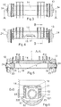
- Fig. 1 shows an exploded view of a wheel axle system 10 including a device according to an embodiment within the scope of the present invention at a wheel axle, which device includes a fixed wheel axle 11, at which a respective wheel 12, 13 is rotatable carried on the two axle ends.
- the wheel axle 11 is connected to a suspension means 14 directly or indirectly fixed to the frame of a tool in such a manner that the wheel axle 11 at one end at least is movable in a vertical direction with respect to the suspension means 14.
- the suspension means is designed to surround at least a part of the wheel axle 11 as a U-formed beam 15 equipped with end openings 16. Within the beam 15 the one end 17 and the other end 18 respectively of the wheel axle can be vertically moved a defined distance.
- the distance is restricted in the vertical direction upwards by spacing means 19 at the top side of the wheel axle 11.
- the spacing means 19 are assembled to top surfaces 20 of rectangular guiding means 21 in turn assembled around the wheel axle 11.
- the guiding means are equipped with length spacing means 221, 222 being assembled to the front and rear surfaces of the guiding means for adjusting of the length position of the wheel axle in the suspension means 14.
- One or more shims 223 being added to the length spacing means.
- the distance mentioned is also restricted in the vertical direction downwards by caps 23 connected to the end openings of the beam 15, said caps being connected to the ends of the beam by screw joints.
- the guiding means 21 are assembled around the wheel axle 11 at the two ends thereof.
- spacing means and length spacing means are assembled at said two ends.
- the two wheels 12, 13 are carried on the wheel axle through respective axle taps 24.
- Fig. 2 shows the wheel axle system 10 as assembled.
- the wheels 12, 13 are assembled on their axle taps 24 and the wheel axle is assembled on the suspension means 14 by the caps 23, connected to the suspension means 14 by screw joints 25.
- the suspension means is equipped with load reinforcements 26 shaped as disk beams being connected to a first assembling device 27 and a second assembling device 28 for the suspension means 14 attachment to a tool vehicle, not shown.
- Fig. 3 shows a top view of the embodiment according to Fig. 2 having the two wheels 12, 13 connected with the axle taps 24 of the wheel axle and the suspension means 14 of the device.
- Fig. 4 shows a front view of the embodiment according to Fig. 2 having the two wheels 12, 13 connected with the axle taps 24 of the wheel axle and the suspension means 14 of the device.
- the figure also shows an adjustment element 41 to stabilize the movements of the wheel axle 11 in the suspension means 14.
- Fig. 5 shows an axial section view A-A according to Fig. 3 having the wheels 12, 13 carried by respective axle taps 24 at the ends of the wheel axle 11, in turn situated inside the suspension means 14.
- the wheel axle 11 bears against the inside of the suspension means 14 through the spacing means 19 at the top side of the wheel axle 11.
- the wheel axle 11 and the spacing means 19 will be forced against the inside and the suspension means 14 as shown by the figure. If the downward directed force F is symmetrically positioned against the suspension means the forces will be distributed onto the wheel axle 11 with F/2 through each one of the spacing means 19 according to the vertically directed arrows in the figure.
- the figure shows that in each one of the caps 23 there is a vertical play 51, 52 allowing the respective end of the wheel axle 11 to be displaced in a vertical direction within the suspension means 14 if there is any uneven load of the suspension means 14.
- Fig. 6 shows a cross section view B-B according to Fig. 4 through the guiding means 21 being assembled around the wheel axle 11.
- the wheel 13 is connected to the wheel axle 11 as described above.
- the figure shows also the play between the wheel axle 11 and the inside of the cap 23.
- the length spacing means 221, 222 are assembled in the length direction on the guiding means 21. These length spacing means are planar and assembled against vertically directed planar sides of the guiding means 21. An adaption of the length spacing means is made to adjust the position of the wheel axle in the length direction in the suspension means 14. Thereby the length spacing means 221, 222 bear against the vertical inner sides 61, 62 of the suspension means 14 according to the figure.
- Fig. 7 shows a first load case at a second embodiment of the invention with numeric references corresponding to those used in Fig. 5 .
- the figure shows a corresponding axial section view having the wheels 12, 13 carried by respective axle taps 24 at the ends of the wheel axle 11, in turn situated inside the suspension means 14.
- the wheel axle 11 bears against the inside of the suspension means 14 through the spacing means 19 at the top side of the wheel axle 11. If the downwards directed force F is symmetrically positioned against the suspension means the forces will be distributed onto the wheel axle 11 with F/2 through each one of the spacing means 19 according to the vertically directed arrows in the figure in the same manner as shown by Fig. 5 .
- the figure shows that in each one of the caps 23 there is a vertical play 51, 52 allowing the respective end of the wheel axle 11 to be displaced in a vertical direction within the suspension means 14 if there is any uneven load of the suspension means 14.
- the base 71 being quite planar, is shown with a dash dotted line.
- the base in the figure represents a rail section where the two rails are quite horizontal with respect to each other, i.e. the load case is quite symmetric. Equal large force is transferred to the contact with the respective base for each one of the wheels 12, 13.
- a tool vehicle is equipped with a front wheel axle 11 and a rear wheel axle, said two wheel axles are in the load case shown situated at a quite horizontal rail section and all the four wheels are in contact with respective rail and the power is symmetrically transferred in dependence of the position of the centre of gravity of the tool vehicle.
- m 1 1.13 t
- Fig. 9 shows a third load case where a tool, e.g. a bucket, is working with a load far away from the position of the centre of gravity of the tool, i.e. at the right hand side in the figure, with a downward directed force, which may correspond to the upward directed force F2 acting on the suspension means 14 left side.
- a tool e.g. a bucket
- a downward directed force which may correspond to the upward directed force F2 acting on the suspension means 14 left side.
- the wheel axle 11 is movable within the area defined upwards by the suspension means 14 and downwards by the cap 23. If all the suspension means 14 was raised such that the two wheels 12, 13 missed the rail contact the wheel axle 11 would be hanging free in the two sides of the cap 23. In such a hypothetical raised position the wheel axle 11 would have a vertically free movement within said area and would be moved upwards in a translatory way until the two sides of the wheel axle are in contact with the suspension means 14. Of course within the scope of such a translatory motion the wheel axle 11 can carry out also angle movements within this area as is shown by Figs. 8 and 9 .
- the invention also comprises other constructions of suspension means which as a whole defines the restricted area for the movements of the wheel axle.
- the suspension means can be designed as a tube with a cylindrical or rectangular cross section having an inside measure exceeding the outside measure of the wheel axle in such a way to define the restricted movement area for the wheel axle.
- the wheel axle is inserted from one end of the suspension means.
- Other constructions of the suspension means may be such that it is designed in an upper part and a lower part being put together around the wheel axle and thereby define the restricted movement area of the wheel axle.
Landscapes
- Engineering & Computer Science (AREA)
- Mechanical Engineering (AREA)
- Vehicle Body Suspensions (AREA)
Claims (9)
- Schienenfahrzeug, das mit einer starren Radachse (11) ausgestattet ist, auf der an jedem der zwei Enden davon ein Rad (12, 13) drehbar angebracht ist, wobei die Radachse (11) mit einem Aufhängungsmittel (14) verbunden ist und durch dieses gehalten ist, das direkt oder indirekt an dem Rahmen des Fahrzeugs auf solche Weise fixiert ist, dass mindestens ein Ende der Radachse (11) in einer vertikalen Richtung in Bezug auf das Aufhängungsmittel (14) beweglich ist, dadurch gekennzeichnet, dass das Aufhängungsmittel (14) zumindest einen Teil der Radachse (11) umgibt, wobei das Aufhängungsmittel (14), allein oder in Kombination mit weiteren Mitteln, angeordnet ist, eine beschränkte freie translatorische Bewegung der Radachse (11) in Bezug auf das Aufhängungsmittel (14) zu erlauben, wobei die beschränkte freie translatorische Bewegung auf eine definierte Distanz innerhalb des Aufhängungsmittels beschränkt ist.
- Schienenfahrzeug nach Anspruch 1, dadurch gekennzeichnet, dass das Aufhängungsmittel (14) einen Träger (15) umfasst, der über der Radachse (11) und diese teilweise umgebend ist und Endöffnungen (16) aufweist, wobei in dem Träger die Radachse (11) translatorisch ohne Last zwischen zwei Endpositionen auf eine vertikale Weise derart beweglich ist, dass ein oder das andere Ende (17, 18) der Radachse (11) eine definierte Distanz unter Last bewegt werden kann.
- Schienenfahrzeug nach einem der Ansprüche 1-2, dadurch gekennzeichnet, dass die Distanz einerseits durch das Aufhängungsmittel (14) und andererseits durch Kappen (23), die mit dem Aufhängungsmittel (14) verbunden sind, beschränkt ist.
- Schienenfahrzeug nach einem der Ansprüche 1-3, dadurch gekennzeichnet, dass Abstandsmittel (19, 221, 222) zwischen der Radachse (11) und dem Aufhängungsmittel (14) angeordnet sind, um eine Kraft dazwischen zu übertragen.
- Schienenfahrzeug nach Anspruch 4, dadurch gekennzeichnet, dass die Abstandsmittel (19) an der Oberseite der Radachse (11) innerhalb des Trägers (15) nahe zu den zwei Enden davon angeordnet sind.
- Schienenfahrzeug nach einem der Ansprüche 4-5, dadurch gekennzeichnet, dass die Abstandsmittel (19, 221, 222) an und um Führungsmittel (21) montiert sind, die an zumindest einen Teil der Radachse (11) montiert sind, wobei die Führungsmittel mit Montageflächen (20) zum Montieren der Abstandsmittel (19, 221, 222) ausgestattet sind.
- Schienenfahrzeug nach Anspruch 6, dadurch gekennzeichnet, dass die Führungsmittel (21) mit einem vorderen Längenabstandsmittel (221) und einem hinteren Längenabstandsmittel (222) ausgestattet sind.
- Schienenfahrzeug nach Anspruch 7, dadurch gekennzeichnet, dass mindestens eines der Längenabstandsmittel (221, 222) mit einer oder mehreren Unterlegscheiben (223) zum Anpassen der Position der Radachse (11) ausgestattet sind.
- Schienenfahrzeug nach einem der Ansprüche 6-8, dadurch gekennzeichnet, dass alle die Aufhängungsflächen (20) ebenflächig sind.
Applications Claiming Priority (2)
| Application Number | Priority Date | Filing Date | Title |
|---|---|---|---|
| SE1351184A SE538487C2 (sv) | 2013-10-07 | 2013-10-07 | Anordning vid en hjulaxel samt rälsbundet fordon med sådan hjulaxel |
| PCT/SE2014/051067 WO2015053682A1 (en) | 2013-10-07 | 2014-09-16 | A device for a wheel axle and a track bounded vehicle with such a wheel axle |
Publications (3)
| Publication Number | Publication Date |
|---|---|
| EP3055181A1 EP3055181A1 (de) | 2016-08-17 |
| EP3055181A4 EP3055181A4 (de) | 2017-06-21 |
| EP3055181B1 true EP3055181B1 (de) | 2021-08-04 |
Family
ID=52813402
Family Applications (1)
| Application Number | Title | Priority Date | Filing Date |
|---|---|---|---|
| EP14852806.0A Active EP3055181B1 (de) | 2013-10-07 | 2014-09-16 | Vorrichtung für eine radachse und spurbegrenztes fahrzeug mit solch einer radachse |
Country Status (4)
| Country | Link |
|---|---|
| EP (1) | EP3055181B1 (de) |
| DK (1) | DK3055181T3 (de) |
| SE (1) | SE538487C2 (de) |
| WO (1) | WO2015053682A1 (de) |
Cited By (1)
| Publication number | Priority date | Publication date | Assignee | Title |
|---|---|---|---|---|
| US20240101165A1 (en) * | 2022-09-26 | 2024-03-28 | Bnsf Railway Company | Locked-axle spring compression system and method |
Citations (8)
| Publication number | Priority date | Publication date | Assignee | Title |
|---|---|---|---|---|
| US2032697A (en) * | 1934-07-09 | 1936-03-03 | Ephraim P Golden | Auto trailer |
| US2798735A (en) * | 1955-01-17 | 1957-07-09 | Standard Steel Works Inc | Multi-spring undercarriage for vehicles |
| US2851282A (en) * | 1956-03-05 | 1958-09-09 | Pogioli Vittorio | Deformable elastic suspension for vehicle |
| US3073620A (en) * | 1960-09-01 | 1963-01-15 | Lord Mfg Co | Spring suspension |
| DE1870692U (de) * | 1963-02-01 | 1963-04-18 | Vibrastop Gummimetall Verbindu | Achsfeder mit verdrehsicherung. |
| GB2180807A (en) * | 1985-05-24 | 1987-04-08 | Milan Dane Trbojevic | Railway car axle assembly with stationary axle |
| WO1991013786A1 (en) * | 1990-03-15 | 1991-09-19 | Utdc Inc. | Suspension system |
| EP0943519A2 (de) * | 1998-03-20 | 1999-09-22 | ABB Daimler-Benz Transportation (Technology) GmbH | Fahrzeugrad, insbesondere für ein Niederflurfahrzeug |
Family Cites Families (8)
| Publication number | Priority date | Publication date | Assignee | Title |
|---|---|---|---|---|
| US1588219A (en) * | 1925-06-20 | 1926-06-08 | Woodman Railway Supply Company | Railroad-car truck |
| US2207848A (en) * | 1934-07-18 | 1940-07-16 | Symington Gould Corp | Railway truck |
| US3249067A (en) * | 1962-10-17 | 1966-05-03 | Kalamazoo Mfg Company | Convertible railway-highway vehicle |
| FR1391385A (fr) * | 1963-09-03 | 1965-03-05 | Lord Mfg Co | Adaptateur pour roulement à rouleaux, en particulier pour voitures de chemin de fer |
| DE2062797C3 (de) * | 1970-12-19 | 1978-10-12 | Thyssen Industrie Ag, 4300 Essen | Federung für Fahrzeuge |
| BE809588A (fr) * | 1974-01-10 | 1974-05-02 | Perfectionnements aux dispositifs de suspension de longerons sur boites d'essieu pour wagons de chemin de fer et applications similaires. | |
| US4438703A (en) * | 1982-02-12 | 1984-03-27 | The Budd Company | Primary suspension system for a railway car |
| GB2184409A (en) * | 1985-12-20 | 1987-06-24 | Krupp Gmbh | Railway crane |
-
2013
- 2013-10-07 SE SE1351184A patent/SE538487C2/sv unknown
-
2014
- 2014-09-16 EP EP14852806.0A patent/EP3055181B1/de active Active
- 2014-09-16 WO PCT/SE2014/051067 patent/WO2015053682A1/en not_active Ceased
- 2014-09-16 DK DK14852806.0T patent/DK3055181T3/da active
Patent Citations (8)
| Publication number | Priority date | Publication date | Assignee | Title |
|---|---|---|---|---|
| US2032697A (en) * | 1934-07-09 | 1936-03-03 | Ephraim P Golden | Auto trailer |
| US2798735A (en) * | 1955-01-17 | 1957-07-09 | Standard Steel Works Inc | Multi-spring undercarriage for vehicles |
| US2851282A (en) * | 1956-03-05 | 1958-09-09 | Pogioli Vittorio | Deformable elastic suspension for vehicle |
| US3073620A (en) * | 1960-09-01 | 1963-01-15 | Lord Mfg Co | Spring suspension |
| DE1870692U (de) * | 1963-02-01 | 1963-04-18 | Vibrastop Gummimetall Verbindu | Achsfeder mit verdrehsicherung. |
| GB2180807A (en) * | 1985-05-24 | 1987-04-08 | Milan Dane Trbojevic | Railway car axle assembly with stationary axle |
| WO1991013786A1 (en) * | 1990-03-15 | 1991-09-19 | Utdc Inc. | Suspension system |
| EP0943519A2 (de) * | 1998-03-20 | 1999-09-22 | ABB Daimler-Benz Transportation (Technology) GmbH | Fahrzeugrad, insbesondere für ein Niederflurfahrzeug |
Cited By (1)
| Publication number | Priority date | Publication date | Assignee | Title |
|---|---|---|---|---|
| US20240101165A1 (en) * | 2022-09-26 | 2024-03-28 | Bnsf Railway Company | Locked-axle spring compression system and method |
Also Published As
| Publication number | Publication date |
|---|---|
| SE1351184A1 (sv) | 2015-04-08 |
| DK3055181T3 (da) | 2021-09-06 |
| SE538487C2 (sv) | 2016-08-02 |
| EP3055181A4 (de) | 2017-06-21 |
| WO2015053682A1 (en) | 2015-04-16 |
| EP3055181A1 (de) | 2016-08-17 |
Similar Documents
| Publication | Publication Date | Title |
|---|---|---|
| DE10232909A1 (de) | Kabinenlagerung für eine Fahrzeugkabine | |
| EP3849828B1 (de) | Radaufhängung und schwinge für ein über einen elektrischen oder pneumatischen motor angetriebenes rad | |
| EP3015296A2 (de) | Neigungsermöglichende radaufhängung für fahrzeuge | |
| JPWO1993004881A1 (ja) | 作業車両の懸架装置 | |
| JP5404037B2 (ja) | パンタグラフを備えた懸架装置 | |
| CN103802629A (zh) | 一种横向轮距与离地间隙均可调的底盘及调节方法 | |
| CN109591534B (zh) | 用于车辆的轴距调节装置 | |
| EP3296249B1 (de) | Artikulierte arbeitsmaschine | |
| EP1958799A1 (de) | Achsaufhängung für Schwerfahrzeuge | |
| JP2008544922A5 (de) | ||
| JP7438235B2 (ja) | 汎用運搬装置のフレーム | |
| EP1572516B1 (de) | Fahrwerk mit neigungssystem für schienenfahrzeuge | |
| NO20181380A1 (de) | ||
| WO2015053682A1 (en) | A device for a wheel axle and a track bounded vehicle with such a wheel axle | |
| DE102010060273A1 (de) | Gewichtsoptimierte Lastkraftfahrzeuge | |
| AT525736B1 (de) | Fahrgestell für ein Kraftfahrzeug | |
| EP3507173B1 (de) | Anordnung und verfahren zur aktivierung einer drehbewegung bei einem fahrzeug oder einer mobilen arbeitsmaschine | |
| CN215971736U (zh) | 矿用自卸车 | |
| CA2232511C (en) | Axle construction for a vehicle | |
| EP3849830B1 (de) | Schräglenkerradaufhängung für ein über einen elektrischen oder pneumatischen motor angetriebenes rad | |
| US6299188B1 (en) | Suspension stop for an agricultural vehicle | |
| DE19621519A1 (de) | Gefederte Achsaufhängung | |
| CN211809914U (zh) | 车辆底盘边缘式支撑装置 | |
| DE102012106951B4 (de) | Kraftfahrzeugachsanordnung mit Neigefunktion | |
| EP3849829B1 (de) | Schräglenkerradaufhängung für ein über einen elektrischen oder pneumatischen motor angetriebenes rad |
Legal Events
| Date | Code | Title | Description |
|---|---|---|---|
| PUAI | Public reference made under article 153(3) epc to a published international application that has entered the european phase |
Free format text: ORIGINAL CODE: 0009012 |
|
| 17P | Request for examination filed |
Effective date: 20160419 |
|
| AK | Designated contracting states |
Kind code of ref document: A1 Designated state(s): AL AT BE BG CH CY CZ DE DK EE ES FI FR GB GR HR HU IE IS IT LI LT LU LV MC MK MT NL NO PL PT RO RS SE SI SK SM TR |
|
| AX | Request for extension of the european patent |
Extension state: BA ME |
|
| DAX | Request for extension of the european patent (deleted) | ||
| A4 | Supplementary search report drawn up and despatched |
Effective date: 20170524 |
|
| RIC1 | Information provided on ipc code assigned before grant |
Ipc: B61F 5/26 20060101AFI20170518BHEP Ipc: B61F 9/00 20060101ALI20170518BHEP |
|
| STAA | Information on the status of an ep patent application or granted ep patent |
Free format text: STATUS: EXAMINATION IS IN PROGRESS |
|
| 17Q | First examination report despatched |
Effective date: 20191017 |
|
| GRAP | Despatch of communication of intention to grant a patent |
Free format text: ORIGINAL CODE: EPIDOSNIGR1 |
|
| STAA | Information on the status of an ep patent application or granted ep patent |
Free format text: STATUS: GRANT OF PATENT IS INTENDED |
|
| INTG | Intention to grant announced |
Effective date: 20210311 |
|
| GRAS | Grant fee paid |
Free format text: ORIGINAL CODE: EPIDOSNIGR3 |
|
| GRAA | (expected) grant |
Free format text: ORIGINAL CODE: 0009210 |
|
| STAA | Information on the status of an ep patent application or granted ep patent |
Free format text: STATUS: THE PATENT HAS BEEN GRANTED |
|
| AK | Designated contracting states |
Kind code of ref document: B1 Designated state(s): AL AT BE BG CH CY CZ DE DK EE ES FI FR GB GR HR HU IE IS IT LI LT LU LV MC MK MT NL NO PL PT RO RS SE SI SK SM TR |
|
| REG | Reference to a national code |
Ref country code: GB Ref legal event code: FG4D |
|
| REG | Reference to a national code |
Ref country code: AT Ref legal event code: REF Ref document number: 1416703 Country of ref document: AT Kind code of ref document: T Effective date: 20210815 |
|
| REG | Reference to a national code |
Ref country code: CH Ref legal event code: EP |
|
| REG | Reference to a national code |
Ref country code: DE Ref legal event code: R096 Ref document number: 602014079271 Country of ref document: DE |
|
| REG | Reference to a national code |
Ref country code: IE Ref legal event code: FG4D |
|
| REG | Reference to a national code |
Ref country code: FI Ref legal event code: FGE |
|
| REG | Reference to a national code |
Ref country code: DK Ref legal event code: T3 Effective date: 20210831 Ref country code: NO Ref legal event code: T2 Effective date: 20210804 |
|
| REG | Reference to a national code |
Ref country code: SE Ref legal event code: TRGR |
|
| REG | Reference to a national code |
Ref country code: LT Ref legal event code: MG9D |
|
| REG | Reference to a national code |
Ref country code: NL Ref legal event code: MP Effective date: 20210804 |
|
| REG | Reference to a national code |
Ref country code: AT Ref legal event code: MK05 Ref document number: 1416703 Country of ref document: AT Kind code of ref document: T Effective date: 20210804 |
|
| PG25 | Lapsed in a contracting state [announced via postgrant information from national office to epo] |
Ref country code: RS Free format text: LAPSE BECAUSE OF FAILURE TO SUBMIT A TRANSLATION OF THE DESCRIPTION OR TO PAY THE FEE WITHIN THE PRESCRIBED TIME-LIMIT Effective date: 20210804 Ref country code: HR Free format text: LAPSE BECAUSE OF FAILURE TO SUBMIT A TRANSLATION OF THE DESCRIPTION OR TO PAY THE FEE WITHIN THE PRESCRIBED TIME-LIMIT Effective date: 20210804 Ref country code: PT Free format text: LAPSE BECAUSE OF FAILURE TO SUBMIT A TRANSLATION OF THE DESCRIPTION OR TO PAY THE FEE WITHIN THE PRESCRIBED TIME-LIMIT Effective date: 20211206 Ref country code: ES Free format text: LAPSE BECAUSE OF FAILURE TO SUBMIT A TRANSLATION OF THE DESCRIPTION OR TO PAY THE FEE WITHIN THE PRESCRIBED TIME-LIMIT Effective date: 20210804 Ref country code: LT Free format text: LAPSE BECAUSE OF FAILURE TO SUBMIT A TRANSLATION OF THE DESCRIPTION OR TO PAY THE FEE WITHIN THE PRESCRIBED TIME-LIMIT Effective date: 20210804 Ref country code: BG Free format text: LAPSE BECAUSE OF FAILURE TO SUBMIT A TRANSLATION OF THE DESCRIPTION OR TO PAY THE FEE WITHIN THE PRESCRIBED TIME-LIMIT Effective date: 20211104 Ref country code: AT Free format text: LAPSE BECAUSE OF FAILURE TO SUBMIT A TRANSLATION OF THE DESCRIPTION OR TO PAY THE FEE WITHIN THE PRESCRIBED TIME-LIMIT Effective date: 20210804 |
|
| PG25 | Lapsed in a contracting state [announced via postgrant information from national office to epo] |
Ref country code: PL Free format text: LAPSE BECAUSE OF FAILURE TO SUBMIT A TRANSLATION OF THE DESCRIPTION OR TO PAY THE FEE WITHIN THE PRESCRIBED TIME-LIMIT Effective date: 20210804 Ref country code: LV Free format text: LAPSE BECAUSE OF FAILURE TO SUBMIT A TRANSLATION OF THE DESCRIPTION OR TO PAY THE FEE WITHIN THE PRESCRIBED TIME-LIMIT Effective date: 20210804 Ref country code: GR Free format text: LAPSE BECAUSE OF FAILURE TO SUBMIT A TRANSLATION OF THE DESCRIPTION OR TO PAY THE FEE WITHIN THE PRESCRIBED TIME-LIMIT Effective date: 20211105 |
|
| PG25 | Lapsed in a contracting state [announced via postgrant information from national office to epo] |
Ref country code: NL Free format text: LAPSE BECAUSE OF FAILURE TO SUBMIT A TRANSLATION OF THE DESCRIPTION OR TO PAY THE FEE WITHIN THE PRESCRIBED TIME-LIMIT Effective date: 20210804 |
|
| REG | Reference to a national code |
Ref country code: DE Ref legal event code: R097 Ref document number: 602014079271 Country of ref document: DE |
|
| REG | Reference to a national code |
Ref country code: CH Ref legal event code: PL |
|
| REG | Reference to a national code |
Ref country code: BE Ref legal event code: MM Effective date: 20210930 |
|
| PG25 | Lapsed in a contracting state [announced via postgrant information from national office to epo] |
Ref country code: SM Free format text: LAPSE BECAUSE OF FAILURE TO SUBMIT A TRANSLATION OF THE DESCRIPTION OR TO PAY THE FEE WITHIN THE PRESCRIBED TIME-LIMIT Effective date: 20210804 Ref country code: SK Free format text: LAPSE BECAUSE OF FAILURE TO SUBMIT A TRANSLATION OF THE DESCRIPTION OR TO PAY THE FEE WITHIN THE PRESCRIBED TIME-LIMIT Effective date: 20210804 Ref country code: RO Free format text: LAPSE BECAUSE OF FAILURE TO SUBMIT A TRANSLATION OF THE DESCRIPTION OR TO PAY THE FEE WITHIN THE PRESCRIBED TIME-LIMIT Effective date: 20210804 Ref country code: MC Free format text: LAPSE BECAUSE OF FAILURE TO SUBMIT A TRANSLATION OF THE DESCRIPTION OR TO PAY THE FEE WITHIN THE PRESCRIBED TIME-LIMIT Effective date: 20210804 Ref country code: EE Free format text: LAPSE BECAUSE OF FAILURE TO SUBMIT A TRANSLATION OF THE DESCRIPTION OR TO PAY THE FEE WITHIN THE PRESCRIBED TIME-LIMIT Effective date: 20210804 Ref country code: CZ Free format text: LAPSE BECAUSE OF FAILURE TO SUBMIT A TRANSLATION OF THE DESCRIPTION OR TO PAY THE FEE WITHIN THE PRESCRIBED TIME-LIMIT Effective date: 20210804 Ref country code: AL Free format text: LAPSE BECAUSE OF FAILURE TO SUBMIT A TRANSLATION OF THE DESCRIPTION OR TO PAY THE FEE WITHIN THE PRESCRIBED TIME-LIMIT Effective date: 20210804 |
|
| PLBE | No opposition filed within time limit |
Free format text: ORIGINAL CODE: 0009261 |
|
| STAA | Information on the status of an ep patent application or granted ep patent |
Free format text: STATUS: NO OPPOSITION FILED WITHIN TIME LIMIT |
|
| 26N | No opposition filed |
Effective date: 20220506 |
|
| PG25 | Lapsed in a contracting state [announced via postgrant information from national office to epo] |
Ref country code: LU Free format text: LAPSE BECAUSE OF NON-PAYMENT OF DUE FEES Effective date: 20210916 Ref country code: IE Free format text: LAPSE BECAUSE OF NON-PAYMENT OF DUE FEES Effective date: 20210916 Ref country code: BE Free format text: LAPSE BECAUSE OF NON-PAYMENT OF DUE FEES Effective date: 20210930 |
|
| PG25 | Lapsed in a contracting state [announced via postgrant information from national office to epo] |
Ref country code: SI Free format text: LAPSE BECAUSE OF FAILURE TO SUBMIT A TRANSLATION OF THE DESCRIPTION OR TO PAY THE FEE WITHIN THE PRESCRIBED TIME-LIMIT Effective date: 20210804 Ref country code: LI Free format text: LAPSE BECAUSE OF NON-PAYMENT OF DUE FEES Effective date: 20210930 Ref country code: CH Free format text: LAPSE BECAUSE OF NON-PAYMENT OF DUE FEES Effective date: 20210930 |
|
| PG25 | Lapsed in a contracting state [announced via postgrant information from national office to epo] |
Ref country code: HU Free format text: LAPSE BECAUSE OF FAILURE TO SUBMIT A TRANSLATION OF THE DESCRIPTION OR TO PAY THE FEE WITHIN THE PRESCRIBED TIME-LIMIT; INVALID AB INITIO Effective date: 20140916 |
|
| P01 | Opt-out of the competence of the unified patent court (upc) registered |
Effective date: 20230329 |
|
| PG25 | Lapsed in a contracting state [announced via postgrant information from national office to epo] |
Ref country code: CY Free format text: LAPSE BECAUSE OF FAILURE TO SUBMIT A TRANSLATION OF THE DESCRIPTION OR TO PAY THE FEE WITHIN THE PRESCRIBED TIME-LIMIT Effective date: 20210804 |
|
| PG25 | Lapsed in a contracting state [announced via postgrant information from national office to epo] |
Ref country code: MK Free format text: LAPSE BECAUSE OF FAILURE TO SUBMIT A TRANSLATION OF THE DESCRIPTION OR TO PAY THE FEE WITHIN THE PRESCRIBED TIME-LIMIT Effective date: 20210804 |
|
| PG25 | Lapsed in a contracting state [announced via postgrant information from national office to epo] |
Ref country code: MT Free format text: LAPSE BECAUSE OF FAILURE TO SUBMIT A TRANSLATION OF THE DESCRIPTION OR TO PAY THE FEE WITHIN THE PRESCRIBED TIME-LIMIT Effective date: 20210804 |
|
| PGFP | Annual fee paid to national office [announced via postgrant information from national office to epo] |
Ref country code: FI Payment date: 20240918 Year of fee payment: 11 |
|
| PGFP | Annual fee paid to national office [announced via postgrant information from national office to epo] |
Ref country code: IT Payment date: 20240917 Year of fee payment: 11 |
|
| PGFP | Annual fee paid to national office [announced via postgrant information from national office to epo] |
Ref country code: DK Payment date: 20250922 Year of fee payment: 12 Ref country code: DE Payment date: 20250917 Year of fee payment: 12 |
|
| PGFP | Annual fee paid to national office [announced via postgrant information from national office to epo] |
Ref country code: NO Payment date: 20250922 Year of fee payment: 12 |
|
| PGFP | Annual fee paid to national office [announced via postgrant information from national office to epo] |
Ref country code: GB Payment date: 20250916 Year of fee payment: 12 |
|
| PGFP | Annual fee paid to national office [announced via postgrant information from national office to epo] |
Ref country code: FR Payment date: 20250917 Year of fee payment: 12 |
|
| PGFP | Annual fee paid to national office [announced via postgrant information from national office to epo] |
Ref country code: SE Payment date: 20250923 Year of fee payment: 12 |
|
| PG25 | Lapsed in a contracting state [announced via postgrant information from national office to epo] |
Ref country code: TR Free format text: LAPSE BECAUSE OF FAILURE TO SUBMIT A TRANSLATION OF THE DESCRIPTION OR TO PAY THE FEE WITHIN THE PRESCRIBED TIME-LIMIT Effective date: 20210804 |
|
| PG25 | Lapsed in a contracting state [announced via postgrant information from national office to epo] |
Ref country code: FI Free format text: LAPSE BECAUSE OF NON-PAYMENT OF DUE FEES Effective date: 20250916 |