EP3055202B1 - Selbstausrichtende montagebeschläge sowie systeme und verfahren zu deren verwendung - Google Patents
Selbstausrichtende montagebeschläge sowie systeme und verfahren zu deren verwendung Download PDFInfo
- Publication number
- EP3055202B1 EP3055202B1 EP14748044.6A EP14748044A EP3055202B1 EP 3055202 B1 EP3055202 B1 EP 3055202B1 EP 14748044 A EP14748044 A EP 14748044A EP 3055202 B1 EP3055202 B1 EP 3055202B1
- Authority
- EP
- European Patent Office
- Prior art keywords
- barrel
- floor
- fitting
- alignment
- side attachment
- Prior art date
- Legal status (The legal status is an assumption and is not a legal conclusion. Google has not performed a legal analysis and makes no representation as to the accuracy of the status listed.)
- Active
Links
Images



Classifications
-
- B—PERFORMING OPERATIONS; TRANSPORTING
- B64—AIRCRAFT; AVIATION; COSMONAUTICS
- B64C—AEROPLANES; HELICOPTERS
- B64C1/00—Fuselages; Constructional features common to fuselages, wings, stabilising surfaces or the like
- B64C1/18—Floors
-
- B—PERFORMING OPERATIONS; TRANSPORTING
- B64—AIRCRAFT; AVIATION; COSMONAUTICS
- B64C—AEROPLANES; HELICOPTERS
- B64C1/00—Fuselages; Constructional features common to fuselages, wings, stabilising surfaces or the like
- B64C1/06—Frames; Stringers; Longerons ; Fuselage sections
- B64C1/068—Fuselage sections
-
- B—PERFORMING OPERATIONS; TRANSPORTING
- B64—AIRCRAFT; AVIATION; COSMONAUTICS
- B64F—GROUND OR AIRCRAFT-CARRIER-DECK INSTALLATIONS SPECIALLY ADAPTED FOR USE IN CONNECTION WITH AIRCRAFT; DESIGNING, MANUFACTURING, ASSEMBLING, CLEANING, MAINTAINING OR REPAIRING AIRCRAFT, NOT OTHERWISE PROVIDED FOR; HANDLING, TRANSPORTING, TESTING OR INSPECTING AIRCRAFT COMPONENTS, NOT OTHERWISE PROVIDED FOR
- B64F5/00—Designing, manufacturing, assembling, cleaning, maintaining or repairing aircraft, not otherwise provided for; Handling, transporting, testing or inspecting aircraft components, not otherwise provided for
- B64F5/10—Manufacturing or assembling aircraft, e.g. jigs therefor
-
- Y—GENERAL TAGGING OF NEW TECHNOLOGICAL DEVELOPMENTS; GENERAL TAGGING OF CROSS-SECTIONAL TECHNOLOGIES SPANNING OVER SEVERAL SECTIONS OF THE IPC; TECHNICAL SUBJECTS COVERED BY FORMER USPC CROSS-REFERENCE ART COLLECTIONS [XRACs] AND DIGESTS
- Y10—TECHNICAL SUBJECTS COVERED BY FORMER USPC
- Y10T—TECHNICAL SUBJECTS COVERED BY FORMER US CLASSIFICATION
- Y10T29/00—Metal working
- Y10T29/49—Method of mechanical manufacture
- Y10T29/49826—Assembling or joining
- Y10T29/49895—Associating parts by use of aligning means [e.g., use of a drift pin or a "fixture"]
- Y10T29/49902—Associating parts by use of aligning means [e.g., use of a drift pin or a "fixture"] by manipulating aligning means
Definitions
- the present disclosure is directed generally to self-aligning fitting assemblies and more particularly to self-aligning fitting assemblies that may be utilized to align a floor grid of an airframe with a fuselage barrel of the airframe and/or to systems and methods that utilize self-aligning fitting assemblies.
- Aircraft often include several different, or discrete, sub-assemblies that are separately manufactured and subsequently combined during assembly of the aircraft.
- Each of these sub-assemblies may be manufactured at different locations (geographically and/or within a given manufacturing facility) to specified manufacturing tolerances.
- these sub-assemblies may be quite large, and assembly of the sub-assemblies to construct the aircraft many present unique manufacturing challenges.
- a floor grid, or passenger floor grid, of an aircraft may be manufactured separately from a fuselage barrel, or fuselage, of the aircraft. Subsequently, the floor grid may be located within and operatively attached to the fuselage barrel. Both the floor grid and the fuselage barrel are relatively large components, and their assembly may require specialized support and/or transportation structures. In addition, alignment of the floor grid with the fuselage barrel may be a time-consuming and/or expensive process that requires a significant amount of manufacturing resources.
- Prior art document WO 2009/138593 A2 discloses the fitting-out of an aircraft by the laying of a floor, particularly in the cockpit of an aircraft.
- the prior art document relates more particularly to a method of fitting out an aircraft and to such an aircraft.
- the aircraft comprises a fuselage part defining an interior volume and at least one internal on-board structure, the said on-board structure being secured to the said fuselage part and designed to accept a floor module.
- the method then involves a step of introducing the floor module into the said volume and a step of attaching the floor module to the said on-board structure.
- the invention provides a self-aligning fitting assembly configured to align and operatively attach a floor grid and a fuselage barrel of an aircraft as defined in claim 1.
- Preferred embodiments of the inventive self-aligning fitting assembly form the subject-matter of dependent claims 2-6.
- the invention provides an airframe comprising such a self-aligning fitting assembly as defined in claim 7.
- the invention provides an airframe assembly system as defined in claim 8 which comprises such an airframe.
- the invention provides a method of assembling an airframe as defined in claim 9. Preferred ways of carrying out this method form the subject-matter of dependent claims 10 and 11.
- Figs. 1-7 provide illustrative, non-exclusive examples of self-aligning fitting assemblies 100 according to the present disclosure, of airframes 50 that may include self-aligning fitting assemblies 100, of airframe assembly systems 20 that may include and/or utilize self-aligning fitting assemblies 100, of components thereof, and/or of methods of utilizing the same.
- Elements that serve a similar, or at least substantially similar, purpose are labeled with like numbers in each of Figs. 1-7 , and these elements may not be discussed in detail herein with reference to each of Figs. 1-7 .
- all elements may not be labeled in each of Figs. 1-7 , but reference numerals associated therewith may be utilized herein for consistency.
- Elements, components, and/or features that are discussed herein with reference to one or more of Figs. 1-7 may be included in and/or utilized with any of Figs. 1-7 without departing from the scope of the present disclosure.
- Fig. 1 is a schematic representation of an airframe 50 according to the present disclosure.
- Airframe 50 may form a portion of, may be utilized with, and/or may be constructed with an airframe assembly system 20 and also may form a portion of an aircraft 48.
- Airframe 50 may include a fuselage barrel 60, a floor grid 80, and a plurality of self-aligning fitting assemblies 100 according to the present disclosure.
- self-aligning fitting assemblies 100 may be selected, designed, adapted, configured, sized, and/or constructed to operatively align floor grid 80 and fuselage barrel 60 during assembly of airframe 50. Additionally or alternatively, self-aligning fitting assemblies 100 also may be selected, designed, adapted, configured, sized, and/or constructed to operatively attach floor grid 80 to fuselage barrel 60 during and/or subsequent to assembly of airframe 50.
- Self-aligning fitting assemblies 100 may include a barrel-side fitting 160, which may be operatively attached to fuselage barrel 60 prior to floor grid 80 being located within fuselage barrel 60.
- Self-aligning fitting assemblies 100 also may include a floor-side fitting 180, which may be operatively attached to floor grid 80 prior to floor grid 80 being located within fuselage barrel 60. Subsequent to floor grid 80 being located within fuselage barrel 60, barrel-side fitting 160 may be operatively attached to floor-side fitting 180 to operatively attach floor grid 80 to fuselage barrel 60.
- Floor grid 80 may define a surface 82, which also may be referred to herein as a passenger surface 82 and/or as an upper surface 82.
- Surface 82 may define (or may be referred to herein as) a surface plane 82 and/or a passenger surface plane 82.
- Surface plane 82 may define a surface normal direction 84.
- Fig. 2 is a schematic representation of illustrative, non-exclusive examples of an airframe assembly system 20 according to the present disclosure that may be utilized to construct at least a portion of an airframe 50.
- Airframe assembly system 20 may be configured to operatively attach a floor grid 80 to a fuselage barrel 60 to define airframe 50.
- Airframe assembly system 20 may include a floor grid translation structure 30 that may be configured to operatively locate floor grid 80 relative to fuselage barrel 60.
- Floor grid translation structure 30 may include and/or be a gantry crane 32 that is configured to operatively translate floor grid 80.
- Floor grid translation structure 30 also may include and/or be a floor grid support jig 34 that is configured to operatively support floor grid 80.
- Airframe assembly system 20 also may include a fuselage barrel support structure 40.
- Fuselage barrel support structure 40 may be configured to operatively support fuselage barrel 60 while floor grid 80 is operatively located with respect thereto.
- fuselage barrel 60 may include one or more barrel-side fittings 160.
- floor grid 80 may include one or more floor-side fittings 180.
- barrel-side fittings 160 and floor-side fittings 180 may form a self-aligning fitting assembly 100.
- Self-aligning fitting assembly 100 may be configured to cooperatively align floor grid 80 and fuselage barrel 60 and/or to operatively attach floor grid 80 to fuselage barrel 60 during and/or subsequent to assembly of airframe 50.
- Fig. 3 is a schematic representation of illustrative, non-exclusive examples of a self-aligning fitting assembly 100 according to the present disclosure.
- Self-aligning fitting assembly 100 also may be referred to herein as a fitting assembly 100 and/or as an assembly 100.
- Assembly 100 is configured to align and operatively attach a floor grid 80 with a fuselage barrel 60 of an airframe 50 and/or of an aircraft 48.
- Self-aligning fitting assembly 100 includes a barrel-side fitting 160 and a floor-side fitting 180.
- Barrel-side fitting 160 is configured to be operatively attached to fuselage barrel 60, such as via one or more barrel-side retention structures 164.
- floor-side fitting 180 is configured to be operatively attached to floor grid 80, such as via one or more floor-side retention structures 184.
- Barrel-side fitting 160 includes and/or defines a plurality of barrel-side attachment holes 162, and floor-side fitting 180 includes and/or defines a plurality of floor-side attachment holes 182.
- Each of the plurality of floor-side attachment holes 182 is designed, adapted, configured, sized, and/or located to be operatively aligned with a respective one of the plurality of barrel-side attachment holes 162, as illustrated in Fig. 3 . This operative alignment may permit insertion of an expanding pin 140 and/or a fastener 150 therethrough, as discussed in more detail herein.
- Self-aligning fitting assembly 100 also includes and/or defines an alignment pin recess 120.
- Alignment pin recess 120 is illustrated in dashed lines in Fig. 3 to indicate that alignment pin recess 120 may be defined by and/or formed within barrel-side fitting 160 or by floor-side fitting 180.
- Alignment pin recess 120 is sized to receive an alignment pin 130, which extends from alignment pin recess 120 to define an alignment surface 132.
- an inside dimension of alignment pin recess 120 may be at least substantially similar to an outer dimension of alignment pin 130.
- alignment pin 130 may be at least substantially immobile relative to alignment pin recess 120 when received therein.
- Self-aligning fitting assembly 100 also includes and/or defines a fitting alignment recess 110.
- Fitting alignment recess 110 is illustrated in dashed lines in Fig. 3 to indicate that fitting alignment recess 110 may be defined by and/or formed within barrel-side fitting 160 or by floor-side fitting 180.
- alignment pin recess 120 will be defined by and/or formed within one of barrel-side fitting 160 or floor-side fitting 180, and fitting alignment recess 110 will be defined by and/or formed within the other of barrel-side fitting 160 and floor-side fitting 180.
- alignment pin 130 When alignment pin 130 is received in alignment pin recess 120 and self-aligning fitting assembly 100 is utilized to align and/or operatively attach fuselage barrel 60 to floor grid 80, alignment pin 130 and/or or alignment surface 132 thereof may extend from alignment pin recess 120 and through fitting alignment recess 110.
- fitting alignment recess 110 may be sized to permit translation of alignment surface 132 therein.
- fitting alignment recess 110 may permit translation of barrel-side fitting 160 relative to floor-side fitting 180.
- This translation may include translation among a plurality of relative orientations that include at least a first relative orientation, in which the plurality of floor-side attachment holes 182 is not aligned with the plurality of barrel-side attachment holes 162, and a second relative orientation, in which the plurality of floor-side attachment holes 182 is aligned with the plurality of barrel-side attachment holes 162. This is discussed in more detail herein with reference to Figs. 5-6 .
- barrel-side fitting 160 may define any suitable number of barrel-side attachment holes 162.
- floor-side fitting 180 may define any suitable number of floor-side attachment holes 182.
- barrel-side fitting 160 may define at least 2, exactly 2, at least 3, exactly 3, at least 4, or exactly 4 barrel-side attachment holes 162; and floor-side fitting 180 may define a corresponding number of floor-side attachment holes 182.
- Alignment pin recess 120 may include any suitable structure that is configured to receive and/or retain alignment pin 130.
- alignment pin recess 120 may include and/or be a hole, a cylindrical hole, a cylindrical hole that is sized to receive a threaded portion of alignment pin 130, and/or a cylindrical hole with a shallow countersink that is sized to receive both the threaded portion of alignment pin 130 and a portion of alignment surface 132.
- alignment pin 130 may include any suitable structure that may be received within alignment pin recess 120 and/or that includes alignment surface 132.
- alignment pin 130 may include and/or be a pin, a bolt, and/or a shoulder bolt.
- Expanding pin 140 when present, may include any suitable structure that may be configured to extend through a selected floor-side attachment hole 182 and also through a corresponding barrel-side attachment hole 162 to operatively align the selected floor-side attachment hole 182 with the corresponding barrel-side attachment hole 162.
- expanding pin 140 may be configured to transition between a contracted conformation, which includes and/or defines a contracted diameter, and an expanded conformation, which includes and/or defines an expanded diameter, with the expanded diameter being greater than the contracted diameter.
- selected floor-side attachment hole 182 may be partially aligned with corresponding barrel-side attachment hole 162, such as via locating alignment pin 130 within alignment pin recess 120 and also within fitting alignment recess 110. Expanding pin 140 then may be located within both the selected floor-side attachment hole 182 and the corresponding barrel-side attachment hole 162 while expanding pin 140 is in the contracted state. Then, expanding pin 140 may be transitioned to the expanded state. This transition of expanding pin 140 may operatively align the selected floor-side attachment hole 182 with the corresponding barrel-side attachment hole 162. A clamping device then may be utilized to at least temporarily fix barrel-side fitting 160 and floor-side fitting 180 in a desired relative orientation.
- Expanding pin 140 then may be removed from the selected floor-side attachment hole 182 and also from the corresponding barrel-side attachment hole 162, thereby permitting a fastener to be located within the selected floor-side attachment hole 182 and also within the corresponding barrel-side attachment hole 162.
- the fastener then may be tightened to retain barrel-side fitting 160 and floor-side fitting 180 in the desired relative orientation. Subsequently, the clamping device may be removed.
- Fig. 4 is an exploded view of a more specific but still illustrative, non-exclusive example of a self-aligning fitting assembly 100 according to the present disclosure.
- Self-aligning fitting assembly 100 of Fig. 4 may include and/or be self-aligning fitting assembly 100 of Figs. 1-3 .
- self-aligning fitting assembly 100 includes a barrel-side fitting 160 and a floor-side fitting 180.
- Barrel-side fitting 160 includes and/or defines a plurality of barrel-side attachment holes 162
- floor-side fitting 180 includes and/or defines a plurality of floor-side attachment holes 182.
- Barrel-side fitting 160 also includes and/or defines a barrel-side retention structure 164 that is configured to operatively attach barrel-side fitting 160 to a fuselage barrel (as illustrated in Fig. 3 at 60).
- floor-side fitting 180 includes and/or defines a floor-side retention structure 184 that is configured to operatively attach floor-side fitting 180 to a floor grid (as illustrated in Fig. 3 at 80).
- Barrel-side fitting 160 further includes and/or defines an alignment pin recess 120.
- Alignment pin recess 120 may be configured to receive an alignment pin 130, such as a shoulder bolt, that includes and/or defines an alignment surface 132.
- alignment pin 130 is illustrated both disassembled from barrel-side fitting 160 (in dashed lines) and assembled with barrel-side fitting 160 (in solid lines).
- Floor-side fitting 180 further includes and/or defines a fitting alignment recess 110.
- fitting alignment recess 110 may be sized to receive alignment pin 130 and/or alignment surface 132 thereof.
- fitting alignment recess 110 may permit alignment pin 130 and/or alignment surface 132 thereof to translate therein and may be shaped to preferentially align barrel-side attachment holes 162 of barrel-side fitting 160 with floor-side attachment holes 182 of floor-side fitting 180.
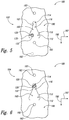
- Figs. 5-6 are partial views of a self-aligning fitting assembly 100 according to the present disclosure.
- the self-aligning fitting assembly of Figs. 5-6 may be included in and/or may be self-aligning fitting assembly 100 of Figs. 1-4 .
- Self-aligning fitting assembly 100 includes a floor-side fitting 180 and a barrel-side fitting 160.
- Barrel-side fitting 160 includes and/or defines an alignment pin recess 120 that has an alignment pin 130 received therein.
- Alignment pin 130 includes and/or defines an alignment surface 132.
- Floor-side fitting 180 includes and/or defines a fitting alignment recess 110, and alignment pin 130 extends through fitting alignment recess 110.
- barrel-side fitting 160 is located behind floor-side fitting 180 and is only visible through fitting alignment recess 110.
- Fitting alignment recess 110 includes and/or defines a first region 112, a second region 114, and a transition region 116 between first region 112 and second region 114.
- First region 112 is sized to permit alignment pin 130 and/or alignment surface 132 to translate therein in both directions that are parallel to a first direction 190 and in directions that are parallel to a second direction 192.
- Second region 114 is sized to permit alignment pin 130 and/or alignment surface 132 to translate therein in directions that are parallel to first direction 190 but to restrict and/or otherwise limit translation of alignment pin 130 and/or alignment surface 132 in directions that are parallel to second direction 192.
- barrel-side fitting 160 and floor-side fitting 180 initially may be brought together in a first orientation 102, which also may be referred to herein as a first relative orientation 102.
- first orientation 102 alignment pin 130 and/or alignment surface 132 thereof may be located within first region 112 of fitting alignment recess 110.
- barrel-side attachment holes 162 of barrel-side fitting 160 may not be aligned with floor-side attachment holes 182 of floor-side fitting 180.
- barrel-side fitting 160 and floor-side fitting 180 may be translated relative to one another to a second orientation 104, which also may be referred to herein as a second relative orientation 104.
- second orientation 104 alignment pin 130 and/or alignment surface 132 thereof may be located within second region 114 of fitting alignment recess 110.
- barrel-side attachment holes 162 of barrel-side fitting 160 may be aligned with, at least partially aligned with, and/or substantially aligned with floor-side attachment holes 182 of floor-side fitting 180.
- transition region 116 may be shaped to preferentially direct alignment pin 130 and/or alignment surface 132 thereof from first region 112 to second region 114.
- a force may be applied to floor-side fitting 180 (and/or to a floor grid 80 that may be attached thereto) to urge alignment pin 130 from first region 112 toward and/or into second region 114 (as illustrated in Fig. 6 ). In Figs. 5-6 , this may include directing the force in first direction 190.
- transitioning from first orientation 102 to second orientation 104 may include translating barrel-side fitting 160 and floor-side fitting 180 relative to one another both in directions that are parallel to first direction 190 and in directions that are parallel to second direction 192.
- a floor grid 80 that may be operatively attached to floor-side fitting 180 may be at least substantially rigid in directions that are parallel to second direction 192 but may be relatively more flexible in directions that are parallel to first direction 190.
- translation of barrel-side fitting 160 and floor-side fitting 180 relative to one another in directions that are parallel to first direction 190 may include deformation of the floor grid 80 in directions that are parallel to first direction 190.
- a fuselage barrel 60 that may be operatively attached to barrel-side fitting 160 may be at least substantially rigid in directions that are parallel to first direction 190 but may be relatively more flexible in directions that are parallel to second direction 192.
- translation of barrel-side fitting 160 and floor-side fitting 180 relative to one another in directions that are parallel to second direction 192 may include deformation of the fuselage barrel 60 in directions that are parallel to second direction 192.
- Fitting alignment recess 110 and/or first region 112, second region 114, and/or transition region 116 thereof may define any suitable shape.
- first region 112 may define a (substantially) trapezoidal shape, a (substantially) isosceles trapezoidal shape, and/or a trapezoidal shape that includes and/or defines two (substantially) rounded corners.
- second region 114 may define a slot that extends from first region 112.
- transition region 116 may provide a (substantially) smooth, gradual, and/or sloped transition from first region 112 to second region 114.
- alignment pin 130 and/or alignment surface 132 thereof may define a circular, or at least substantially circular, cross-sectional shape.
- a width of the slot may be greater than a diameter of alignment pin 130.
- the width of the slot also may be within a threshold fraction of the diameter of alignment pin 130.
- Illustrative, non-exclusive examples of the threshold fraction include threshold fractions of less than 1%, less than 2%, less than 3%, less than 4%, less than 5%, less than 6%, less than 7%, less than 8%, less than 9%, or less than 10% of the diameter of alignment pin 130.
- Fig. 7 is a flowchart depicting methods 300 according to the present disclosure of assembling an airframe.
- some steps are illustrated in dashed boxes indicating that such steps may be optional or may correspond to an optional version of methods 300 according to the present disclosure. That said, not all methods 300 according to the present disclosure are required to include the steps illustrated in solid boxes.
- the methods and steps illustrated in Fig. 7 are not limiting and other methods and steps are within the scope of the present disclosure, including methods having greater than or fewer than the number of steps illustrated, as understood from the discussions herein.
- Methods 300 may include operatively supporting a floor grid at 305 and/or operatively supporting a fuselage barrel at 310. Methods 300 include translating the floor grid relative to the fuselage barrel at 315, operatively aligning a plurality of alignment pin recesses with a plurality of fitting alignment recesses at 320, locating a plurality of alignment pins within the plurality of alignment pin recesses at 325, and lowering the floor grid relative to the fuselage barrel at 330.
- Methods 300 further may include locating a plurality of expanding pins within the airframe at 335, expanding the plurality of expanding pins at 340, clamping a plurality of floor-side fittings to a corresponding plurality of barrel-side fittings at 345, and/or removing the plurality of expanding pins from the airframe at 350.
- Methods 300 further include installing a plurality of fasteners within the airframe at 355 and also may include removing the plurality of alignment pins at 360.
- Translating the floor grid relative to the fuselage barrel at 315 may include translating to operatively locate the floor grid within the fuselage barrel.
- the floor grid may be operatively attached to the plurality of floor-side fittings and the fuselage barrel may be operatively attached to the plurality of barrel-side fittings.
- the plurality of floor-side fittings may define a plurality of floor-side attachment holes and the plurality of barrel-side fittings may define a plurality of barrel-side attachment holes.
- Each of the plurality of floor-side fittings together with a corresponding barrel-side fitting of the plurality of barrel-side fittings may form a self-aligning fitting assembly, such as self-aligning fitting assembly 100 of Figs. 1-6 .
- Operatively aligning the plurality of alignment pin recesses with the plurality of fitting alignment recesses at 320 may include operatively aligning to permit the locating at 325.
- the plurality of alignment pin recesses may be defined by and/or formed within one of the plurality of floor-side fittings and the plurality of barrel-side fittings.
- the floor grid may define a passenger surface that has a surface normal direction
- the operatively aligning at 320 may include deforming the floor grid in a direction that is (at least substantially) parallel to the surface normal direction.
- the operatively aligning at 320 also may include deforming the fuselage barrel in a direction that is (at least substantially) perpendicular to the surface normal direction.
- the deforming the floor grid may be performed (at least substantially) concurrently with the deforming the fuselage barrel.
- Locating the plurality of alignment pins within the plurality of alignment pin recesses at 325 may include locating the plurality of alignment pins in any suitable manner.
- the locating at 325 may include bolting and/or threading the plurality of alignment pins into the plurality of alignment pin recesses.
- the locating at 325 also may include placing, inserting, and/or pressing the plurality of alignment pins into the plurality of alignment pin recesses.
- the plurality of alignment pins may define a plurality of respective alignment surfaces, and the locating at 325 also may include extending the plurality of alignment pins (and/or the plurality of alignment surfaces thereof) through respective fitting alignment recesses. Thus, and subsequent to the locating at 325, each of the plurality of alignment pins may extend within a respective alignment pin recess and through a corresponding fitting alignment recess.
- Lowering the floor grid relative to the fuselage barrel at 330 may include lowering the floor grid to translate the plurality of barrel-side fittings and the plurality of floor-side fittings relative to one another. This may include translating from a first orientation, in which the plurality of floor-side attachment holes is not aligned with the plurality of barrel-side attachment holes, to a second orientation, in which each of the plurality of floor-side attachment holes is at least partially aligned with a corresponding barrel-side attachment hole of the plurality of barrel-side attachment holes.
- the fitting alignment recess may be shaped to direct, or preferentially direct, the plurality of floor-side fittings and the plurality of barrel-side fittings toward the second orientation during the lowering at 330.
- Locating the plurality of expanding pins within the airframe at 335 may be performed subsequent to the lowering at 330 and/or prior to the installing at 355.
- the locating at 335 may include locating the plurality of expanding pins in any suitable manner.
- the locating at 335 may include extending each of the plurality of expanding pins through a selected floor-side attachment hole of the plurality of floor-side attachment holes and also through a corresponding barrel-side attachment hole of the plurality of barrel-side attachment holes.
- Expanding the plurality of expanding pins at 340 may include expanding subsequent to the locating at 335. As discussed in more detail herein, and prior to the expanding at 340, each of the floor-side attachment holes and the corresponding barrel-side attachment hole may be partially, but not completely aligned. This partial alignment may be sufficient to permit the locating at 335 but insufficient to permit the installing at 355. With this in mind, the expanding at 340 may include expanding the plurality of expanding pins, such as by increasing an outer diameter thereof, to align each of the plurality of floor-side attachment holes with the corresponding barrel-side attachment hole, such as to permit the installing at 355.
- Clamping the plurality of floor-side fittings to the corresponding plurality of barrel-side fittings at 345 may include clamping to (at least substantially) restrict relative motion between the plurality of floor-side fittings and the plurality of barrel-side fittings. Additionally or alternatively, the clamping at 345 may include clamping to retain alignment of each of the plurality of floor-side attachment holes with the corresponding barrel side attachment hole.
- Removing the plurality of expanding pins from the airframe at 350 may include removing the plurality of expanding pins to permit the installing at 355. This may include removing each of the plurality of expanding pins from the selected floor-side attachment hole and also from the corresponding barrel-side attachment hole. The removing at 350 may be subsequent to the clamping at 345. Thus, the removing at 350 may include removing the plurality of expanding pins while retaining the alignment between each of the plurality of floor-side attachment holes and the corresponding barrel-side attachment hole via the clamping at 345.
- Installing the plurality of fasteners within the airframe at 355 may include extending each of the plurality of fasteners through a selected one of the plurality of floor-side attachment holes and also through a corresponding one of the plurality of barrel-side attachment holes.
- the installing at 355 also may include tightening the plurality of fasteners.
- methods 300 include the clamping at 345
- methods 300 further may include unclamping the plurality of floor-side fittings from the corresponding plurality of barrel-side fittings subsequent to the installing at 355.
- methods 300 include the removing at 350
- the installing at 355 may be subsequent to the removing at 350.
- Removing the plurality of alignment pins at 360 may include removing the plurality of alignment pins in any suitable manner.
- the removing at 360 may include removing the plurality of alignment pins from the plurality of alignment pin recesses.
- the removing at 360 also may include removing the plurality of alignment pins from the airframe.
- the terms “adapted” and “configured” mean that the element, component, or other subject matter is designed and/or intended to perform a given function. Thus, the use of the terms “adapted” and “configured” should not be construed to mean that a given element, component, or other subject matter is simply “capable of' performing a given function but that the element, component, and/or other subject matter is specifically selected, created, implemented, utilized, programmed, and/or designed for the purpose of performing the function. It is also within the scope of the present disclosure that elements, components, and/or other recited subject matter that is recited as being adapted to perform a particular function may additionally or alternatively be described as being configured to perform that function, and vice versa. Similarly, subject matter that is recited as being configured to perform a particular function may additionally or alternatively be described as being operative to perform that function.
Landscapes
- Engineering & Computer Science (AREA)
- Aviation & Aerospace Engineering (AREA)
- Mechanical Engineering (AREA)
- Manufacturing & Machinery (AREA)
- Transportation (AREA)
- Connection Of Plates (AREA)
- Automatic Assembly (AREA)
- Body Structure For Vehicles (AREA)
- Floor Finish (AREA)
Claims (11)
- Selbstausrichtende Anordnung (100) von Montageteilen, die dazu konfiguriert ist, ein Bodengitter (80) und eine Rumpfsektion (60) eines Flugzeugs auszurichten und betriebsmäßig zu befestigen, wobei die Anordnung umfasst:
ein rumpfseitiges Montageteil (160), das dazu konfiguriert ist, betriebsmäßig an der Rumpfsektion befestigt zu werden, wobei das rumpfseitige Montageteil eine Mehrzahl von rumpfseitigen Befestigungslöchern (162) aufweist:ein bodenseitiges Montageteil (180), das dazu konfiguriert ist, betriebsmäßig an dem Bodengitter und dem rumpfseitigen Montageteil befestigt zu werden, wobei das bodenseitige Montageteil eine Mehrzahl von bodenseitigen Befestigungslöchern (182) umfasst, und wobei weiterhin jedes aus der Mehrzahl von bodenseitigen Befestigungslöchern dazu konfiguriert ist, betriebsmäßig mit einem jeweiligen aus der Mehrzahl von rumpfseitigen Befestigungslöchern ausgerichtet zu werden;eine Aussparung (120) für einen Ausrichtungsstift;eine Aussparung (110) zur Montageteilausrichtung; undeinen Ausrichtungsstift (130), der eine Ausrichtungsoberfläche (132) umfasst;
wobei:(i) die Aussparung für den Ausrichtungsstift in einem aus dem rumpfseitigen Montageteil oder dem bodenseitigen Montageteil ausgebildet ist und dazu konfiguriert ist, den Ausrichtungsstift aufzunehmen;(ii) die Aussparung zur Montageteilausrichtung in dem anderen aus dem rumpfseitigen Montageteil und dem bodenseitigen Montageteil ausgebildet ist;(iii) der Ausrichtungsstift in der Aussparung für den Ausrichtungsstift aufgenommen wird und die Ausrichtungsoberfläche sich durch die Aussparung zur Montageteilausrichtung erstreckt;(iv) die Aussparung zur Montageteilausrichtung dazu abgemessen ist, eine Verschiebung der Ausrichtungsoberfläche darin zu ermöglichen, wodurch eine Verschiebung des rumpfseitigen Montageteils und des bodenseitigen Montageteils im Verhältnis zueinander in einer Mehrzahl von relativen Ausrichtungen zwischen einer ersten Lage (102), in der die Mehrzahl von bodenseitigen Montageteilen nicht mit der Mehrzahl von rumpfseitigen Montageteilen ausgerichtet ist, und einer zweiten Lage (104), in der die Mehrzahl von bodenseitigen Montageteilen mit der Mehrzahl von rumpfseitigen Montageteilen ausgerichtet ist, zu ermöglichen; und(v) die Aussparung (110) zur Montageteilausrichtung umfasst:(a) einen ersten Bereich (112), der dazu abgemessen ist, es der Ausrichtungsoberfläche (132) zu ermöglichen, sich darin in Richtungen, die parallel zu einer ersten Richtung (190) verlaufen, und in Richtungen, die parallel zu einer zweiten Richtung (192) rechtwinklig zu der ersten Richtung verlaufen, zu verschieben;(b) einen zweiten Bereich (114), der dazu abgemessen ist, es der Ausrichtungsoberfläche zu ermöglichen, sich darin in Richtungen, die parallel zu der ersten Richtung verlaufen, zu verschieben, aber eine Verschiebung der Ausrichtungsoberfläche in Richtungen, die parallel zu einer zweiten Richtung verlaufen, einzuschränken;(c) einen Übergangsbereich (116) zwischen dem ersten Bereich (112) und dem zweiten Bereich (114), wobei der Übergangsbereich derart geformt ist, dass er vorzugsweise die Ausrichtungsoberfläche (132) aus dem ersten Bereich in den zweiten Bereich lenkt; und wobei die erste Lage (102) einer Situation entspricht, bei der die Ausrichtungsoberfläche innerhalb des ersten Bereichs angeordnet ist, und weiterhin wobei die zweite Lage (104) einer Situation entspricht, bei der die Ausrichtungsoberfläche innerhalb des zweiten Bereichs angeordnet ist. - Anordnung (100) nach Anspruch 1, wobei der erste Bereich (112) eine Trapezform aufweist; und wobei der zweite Bereich (114) einen Schlitz umfasst, der sich von dem ersten Bereich erstreckt.
- Anordnung (100) nach Anspruch 1 oder 2, wobei das rumpfseitige Montageteil (160) eine rumpfseitige Rückhaltestruktur (164) umfasst, die dazu konfiguriert ist, das rumpfseitige Montageteil betriebsmäßig an der Rumpfsektion (60) zu befestigen, und wobei weiterhin das bodenseitige Montageteil (180) eine bodenseitige Rückhaltestruktur (184) umfasst, die dazu konfiguriert ist, das bodenseitige Montageteil betriebsmäßig an dem Bodengitter (80) zu befestigen.
- Anordnung (100) nach einem der vorstehenden Ansprüche, wobei es sich bei dem Ausrichtungsstift (130) um einen Ansatzbolzen handelt.
- Anordnung (100) nach einem der vorstehenden Ansprüche, wobei die Anordnung einen Ausdehnungsstift (140) umfasst, der dazu konfiguriert ist, ein ausgewähltes bodenseitiges Befestigungsloch aus der Mehrzahl von bodenseitigen Befestigungslöchern (182) mit einem entsprechenden rumpfseitigen Befestigungsloch aus der Mehrzahl von rumpfseitigen Befestigungslöchern (162) betriebsmäßig auszurichten, und wobei weiterhin der Ausdehnungsstift dazu konfiguriert ist, zwischen einer kontrahierten Konformation, die einen kontrahierten Durchmesser aufweist, und einer ausgedehnten Konformation, die einen ausgedehnten Durchmesser aufweist, zu wechseln, um das ausgewählte bodenseitige Befestigungsloch mit dem entsprechenden rumpfseitigen Befestigungsloch betriebsmäßig auszurichten, wobei der kontrahierte Durchmesser kleiner als der ausgedehnte Durchmesser ist.
- Anordnung (100) nach einem der vorstehenden Ansprüche, wobei die Anordnung weiterhin eine Mehrzahl von Befestigungselementen umfasst, wobei sich jedes aus der Mehrzahl von Befestigungselementen durch ein ausgewähltes bodenseitiges Befestigungsloch aus der Mehrzahl von bodenseitigen Befestigungslöchern (182) und ebenfalls durch ein entsprechendes rumpfseitiges Befestigungsloch aus der Mehrzahl von rumpfseitigen Befestigungslöchern (162) erstreckt, um das rumpfseitige Montageteil (160) an dem bodenseitigen Montageteil (180) betriebsmäßig zu befestigen.
- Flugwerk (50), das umfasst:die selbstausrichtende Anordnung (100) von Montageteilen nach einem der vorstehenden Ansprüche;eine Rumpfsektion (60); undein Bodengitter (80), wobei das rumpfseitige Montageteil (160) betriebsmäßig an der Rumpfsektion befestigt ist, und wobei weiterhin das bodenseitige Montageteil (180) mit dem Bodengitter betriebsmäßig befestigt ist.
- Flugwerkmontagesystem (20), das dazu konfiguriert ist, ein Bodengitter (80) mit einer Rumpfsektion (60) auszurichten und betriebsmäßig an dieser zu befestigen, wobei das System umfasst:eine Bodengitterverschiebungsstruktur (30), die dazu konfiguriert ist, das Bodengitter zu tragen und das Bodengitter betriebsmäßig im Verhältnis zu der Rumpfsektion anzuordnen;eine Rumpfsektionsträgerstruktur (40), die dazu konfiguriert ist, die Rumpfsektion betriebsmäßig zu tragen; unddas Flugwerk (50) nach Anspruch 7.
- Verfahren zur Montage eines Flugwerks (50), wobei das Verfahren umfasst:Verschieben eines Bodengitters (80) im Verhältnis zu einer Rumpfsektion (60), um das Bodengitter betriebsmäßig innerhalb der Rumpfsektion anzuordnen, wobei das Bodengitter betriebsmäßig an einer Mehrzahl von bodenseitigen Montageteilen (180), die eine Mehrzahl von bodenseitigen Befestigungslöchern (182) umfasst, befestigt ist, und wobei weiterhin die Rumpfsektion betriebsmäßig an einer Mehrzahl von rumpfseitigen Montageteilen (160), die eine Mehrzahl von rumpfseitigen Befestigungslöchern (162) umfasst, befestigt ist;betriebsmäßiges Ausrichten einer Mehrzahl von Aussparungen (120) für Ausrichtungsstifte mit einer entsprechenden Mehrzahl von Aussparungen (110) zur Montageteilausrichtung, wobei die Mehrzahl von Aussparungen für Ausrichtungsstifte innerhalb der Mehrzahl von bodenseitigen Montageteilen oder der Mehrzahl von rumpfseitigen Montageteilen ausgebildet ist, und wobei weiterhin die Mehrzahl von Aussparungen zur Montageteilausrichtung innerhalb der anderen aus der Mehrzahl von bodenseitigen Montageteilen und der Mehrzahl von rumpfseitigen Montageteilen ausgebildet ist;Anordnen einer Mehrzahl von Ausrichtungsstiften (130) innerhalb der Mehrzahl von Aussparungen für Ausrichtungsstifte, wobei die Mehrzahl von Ausrichtungsstiften eine Mehrzahl von Ausrichtungsoberflächen (132) umfasst, und wobei weiterhin das Anordnen das Erstrecken der Mehrzahl von Ausrichtungsoberflächen durch jeweilige Aussparungen zur Montageteilausrichtung aus der Mehrzahl von Aussparungen zur Montageteilausrichtung umfasst;Absenken des Bodengitters im Verhältnis zu der Rumpfsektion, um die Mehrzahl von rumpfseitigen Montageteilen und die Mehrzahl von bodenseitigen Montageteilen im Verhältnis zueinander von einer ersten Lage (102), in der die Mehrzahl von bodenseitigen Montageteilen nicht mit der Mehrzahl von rumpfseitigen Montageteilen ausgerichtet ist, in eine zweite Lage (104), in der jedes aus der Mehrzahl von bodenseitigen Befestigungslöchern wenigstens zum Teil mit einem entsprechenden rumpfseitigen Befestigungsloch aus der Mehrzahl von rumpfseitigen Befestigungslöchern ausgerichtet ist, zu verschieben, wobei die Mehrzahl von Aussparungen zur Montageteilausrichtung dazu ausgeformt ist, die Mehrzahl von bodenseitigen Montageteilen und die Mehrzahl von rumpfseitigen Montageteilen während des Absenkens in Richtung der zweiten Lage zu lenken; undInstallieren einer Mehrzahl von Befestigungselementen innerhalb des Flugwerks durch Erstrecken jedes aus der Mehrzahl von Befestigungselementen durch ein ausgewähltes Befestigungsloch aus der Mehrzahl von rumpfseitigen Befestigungslöchern und ebenso durch ein entsprechendes Befestigungsloch aus der Mehrzahl von bodenseitigen Befestigungslöchern;wobei nach dem Absenken des Bodengitters (80) im Verhältnis zu der Rumpfsektion (60) und vor dem Installieren das Verfahren weiterhin umfasst: Anordnen einer Mehrzahl von Ausdehnungsstiften (140) innerhalb des Flugwerks (50), wobei jeder aus der Mehrzahl von Ausdehnungsstiften sich durch ein ausgewähltes bodenseitiges Befestigungsloch (182) und ebenso durch ein entsprechendes rumpfseitiges Befestigungsloch (162) erstreckt; undwobei das Verfahren weiterhin umfasst:Ausdehnen der Mehrzahl von Ausdehnungsstiften (140), um jedes aus der Mehrzahl von bodenseitigen Befestigungslöchern (182) mit dem entsprechenden rumpfseitigen Befestigungsloch (162) auszurichten; undKlemmen jedes aus der Mehrzahl von bodenseitigen Montageteilen (180) auf ein entsprechendes rumpfseitiges Montageteil (160), um eine relative Bewegung dazwischen einzuschränken, wobei das Verfahren nach dem Klemmen weiterhin umfasst: Entfernen jedes aus der Mehrzahl von Ausdehnungsstiften aus dem ausgewählten bodenseitigen Befestigungsloch und dem entsprechenden rumpfseitigen Befestigungsloch.
- Verfahren nach Anspruch 9, wobei das Verfahren nach dem Installieren weiterhin umfasst: Entfernen der Mehrzahl von Ausrichtungsstiften (130) aus der Mehrzahl von Aussparungen (120) für Ausrichtungsstifte.
- Verfahren nach Anspruch 9 oder 10, wobei das Bodengitter (80) eine Passagierfläche (82) umfasst, die eine Passagieroberflächenebene aufweist, die eine Oberflächennormalenrichtung (84) aufweist, und wobei weiterhin das betriebsmäßige Ausrichten umfasst: Verformen des Bodengitters in einer Richtung, die im Wesentlichen parallel zu der Oberflächennormalenrichtung ist, und gleichzeitiges Verformen der Rumpfsektion (60) in einer Richtung, die im Wesentlichen rechtwinklig zu der Oberflächennormalenrichtung ist.
Applications Claiming Priority (3)
| Application Number | Priority Date | Filing Date | Title |
|---|---|---|---|
| US201361889186P | 2013-10-10 | 2013-10-10 | |
| US14/261,217 US9199715B2 (en) | 2013-10-10 | 2014-04-24 | Self-aligning fitting assemblies and systems and methods including the same |
| PCT/US2014/046968 WO2015053836A1 (en) | 2013-10-10 | 2014-07-17 | Self-aligning fitting assemblies and systems and methods including the same |
Publications (2)
| Publication Number | Publication Date |
|---|---|
| EP3055202A1 EP3055202A1 (de) | 2016-08-17 |
| EP3055202B1 true EP3055202B1 (de) | 2019-03-06 |
Family
ID=52808839
Family Applications (1)
| Application Number | Title | Priority Date | Filing Date |
|---|---|---|---|
| EP14748044.6A Active EP3055202B1 (de) | 2013-10-10 | 2014-07-17 | Selbstausrichtende montagebeschläge sowie systeme und verfahren zu deren verwendung |
Country Status (6)
| Country | Link |
|---|---|
| US (1) | US9199715B2 (de) |
| EP (1) | EP3055202B1 (de) |
| JP (1) | JP6359094B2 (de) |
| CN (1) | CN105555660B (de) |
| ES (1) | ES2727708T3 (de) |
| WO (1) | WO2015053836A1 (de) |
Families Citing this family (8)
| Publication number | Priority date | Publication date | Assignee | Title |
|---|---|---|---|---|
| FR3018267B1 (fr) * | 2014-03-07 | 2017-12-22 | Airbus Operations Sas | Dispositif de positionnement relatif de deux pieces telles qu'une traverse et un cadre de fuselage |
| US10001158B2 (en) * | 2015-08-14 | 2018-06-19 | The Boeing Company | Anti-rotation for eccentric bushings |
| US10173270B2 (en) | 2016-01-29 | 2019-01-08 | The Boeing Company | Countersinking device and associated method |
| WO2017152979A1 (de) * | 2016-03-10 | 2017-09-14 | Siemens Aktiengesellschaft | Verfahren und vorrichtung zur zuordnung von baugruppen auf bestückungslinien |
| US10450053B2 (en) * | 2016-05-11 | 2019-10-22 | The Boeing Company | Methods using predictive shimming to optimize part-to-part alignment |
| WO2020016817A1 (en) * | 2018-07-17 | 2020-01-23 | Compart Systems Pte. Ltd. | Mounting structures for flow substrates |
| FR3130763A1 (fr) | 2021-12-16 | 2023-06-23 | Airbus Operations | Procédé d’assemblage d’un tronçon de fuselage d’un aéronef utilisant un module de plancher comme conformateur de forme. |
| EP4311780B1 (de) * | 2022-07-25 | 2025-09-03 | Airbus Operations SAS | Bezugspositionvorrichtung zur positionierung von mindestens einem kabinenbodengitter und einer seitenschale eines flugzeugs relativ zueinander für die montage eines flugzeugrumpfes |
Family Cites Families (24)
| Publication number | Priority date | Publication date | Assignee | Title |
|---|---|---|---|---|
| US3045834A (en) | 1957-07-25 | 1962-07-24 | Edward A Seiz | Rack construction |
| US3288192A (en) | 1964-09-01 | 1966-11-29 | Carl G Bollinger | Bolt-like member and mounting therefor |
| NL9001014A (nl) * | 1990-04-27 | 1991-11-18 | Koninkl Philips Electronics Nv | Gereedschapsmachine met verplaatsbare positioneerinrichting. |
| US5560102A (en) * | 1992-10-13 | 1996-10-01 | The Boeing Company | Panel and fuselage assembly |
| BE1008803A6 (nl) | 1994-10-13 | 1996-08-06 | Sleutel Bouw N V De | Verbindingsplaat. |
| US6855099B2 (en) * | 2001-10-31 | 2005-02-15 | The Boeing Company | Manufacturing system for aircraft structures and other large structures |
| WO2005012085A1 (de) * | 2003-07-18 | 2005-02-10 | Telair International Gmbh | Frachtraumboden für ein flugzeug und verfahren zu dessen montage |
| US7182291B2 (en) * | 2005-03-23 | 2007-02-27 | The Boeing Company | Integrated aircraft structural floor |
| DE102005054869A1 (de) * | 2005-11-17 | 2007-05-31 | Airbus Deutschland Gmbh | Verfahren zur Herstellung einer Rumpfzelle eines Luftfahrzeugs |
| US7524154B2 (en) * | 2005-11-28 | 2009-04-28 | The Boeing Company | Eccentric fastening device |
| US7527223B2 (en) | 2006-04-06 | 2009-05-05 | The Boeing Company | Interior panel attachment system |
| US7775478B2 (en) * | 2006-09-29 | 2010-08-17 | The Boeing Company | Floor beam assembly, system, and associated method |
| US7497638B2 (en) * | 2006-11-09 | 2009-03-03 | The Boeing Company | Socket joint for tie-rod attachment system and method |
| US7721992B2 (en) * | 2007-03-07 | 2010-05-25 | The Boeing Company | Aircraft floor to fuselage attachment |
| US7765703B2 (en) * | 2007-08-09 | 2010-08-03 | The Boeing Company | Centering mandrel |
| US7967251B2 (en) * | 2008-03-18 | 2011-06-28 | The Boeing Company | Truss network for aircraft floor attachment |
| WO2009124832A2 (de) * | 2008-04-10 | 2009-10-15 | Airbus Operations Gmbh | Flugzeug mit kraftübertragungselement zwischen einem kabinenstrukturelement und einer primärstruktur |
| FR2930521B1 (fr) | 2008-04-29 | 2010-09-03 | Airbus France | Module de plancher d'aeronef, structure et procede de fixation d'un tel module, aeronef comprenant ceux-ci |
| FR2937303B1 (fr) * | 2008-10-16 | 2011-01-14 | Airbus France | Plancher en materiau composite pour vehicule de transport et procede de fabrication d'un tel plancher |
| FR2947524B1 (fr) * | 2009-07-02 | 2011-12-30 | Airbus Operations Sas | Procede de fabrication d'un aeronef comprenant un plancher |
| JP2011158055A (ja) * | 2010-02-03 | 2011-08-18 | Pascal Engineering Corp | 位置決めピン |
| DE102010013370B8 (de) * | 2010-03-30 | 2013-12-12 | Eads Deutschland Gmbh | Wandbauteil für ein Luftfahrzeug |
| JP6090931B2 (ja) * | 2013-10-02 | 2017-03-08 | 三菱重工業株式会社 | 継手及び航空機構造 |
| DE102013113393A1 (de) * | 2013-12-03 | 2015-06-03 | Airbus Operations Gmbh | Verbindungsanordnung und Struktur |
-
2014
- 2014-04-24 US US14/261,217 patent/US9199715B2/en active Active
- 2014-07-17 ES ES14748044T patent/ES2727708T3/es active Active
- 2014-07-17 EP EP14748044.6A patent/EP3055202B1/de active Active
- 2014-07-17 WO PCT/US2014/046968 patent/WO2015053836A1/en not_active Ceased
- 2014-07-17 CN CN201480051396.0A patent/CN105555660B/zh active Active
- 2014-07-17 JP JP2016518154A patent/JP6359094B2/ja active Active
Non-Patent Citations (1)
| Title |
|---|
| None * |
Also Published As
| Publication number | Publication date |
|---|---|
| US20150102170A1 (en) | 2015-04-16 |
| CN105555660A (zh) | 2016-05-04 |
| WO2015053836A1 (en) | 2015-04-16 |
| EP3055202A1 (de) | 2016-08-17 |
| JP2016536185A (ja) | 2016-11-24 |
| ES2727708T3 (es) | 2019-10-18 |
| JP6359094B2 (ja) | 2018-07-18 |
| CN105555660B (zh) | 2018-08-10 |
| US9199715B2 (en) | 2015-12-01 |
Similar Documents
| Publication | Publication Date | Title |
|---|---|---|
| EP3055202B1 (de) | Selbstausrichtende montagebeschläge sowie systeme und verfahren zu deren verwendung | |
| US8272118B2 (en) | Method of preparing the connection between two fuselage sections of an aircraft | |
| CN108281932B (zh) | 自转位螺母板 | |
| US20180016008A1 (en) | Aircraft Monument Floor Mounting System | |
| US9981367B2 (en) | Exterior indexing process and tooling | |
| US20110265300A1 (en) | Device for temporarily fixing in position two fuselage sections to be joined | |
| EP2465774A1 (de) | Adapter und Verfahren zum Installieren von Säulen | |
| CN105756316A (zh) | 自锁安装无损拆除构件 | |
| JP2018024414A (ja) | 分割された胴体アセンブリにおける輪郭保持 | |
| US9156538B1 (en) | Aircraft skin attachment system | |
| CN105197247B (zh) | 一种夹持式航空发动机主安装节机构 | |
| US9739568B2 (en) | Methods of connecting testing equipment to a missile system | |
| JP6279585B2 (ja) | 調節機構が組み込まれたラッチ | |
| US20140186559A1 (en) | Self-stiffened skin for aircraft fuselage including stringers with a closed section and associated manufacturing method | |
| US10071795B2 (en) | Clamp device for use with a decompression panel in an aircraft assembly | |
| US10414480B2 (en) | Sidewall mounting hardware for aircraft | |
| CN103373479B (zh) | 一种宇航单机锁紧释放装置 | |
| US9994298B2 (en) | System for embedded removable aperture | |
| EP2784332A1 (de) | Befestigungssystem | |
| US20210031898A1 (en) | Pressure bulkhead system, pressure bulkhead assembly support tool, and method for assembling a pressure bulkhead system | |
| US10655663B2 (en) | Apparatus, system, and method for aligning apertures of structures | |
| CN210707864U (zh) | 无人机脚架及其无人机 | |
| CN209256728U (zh) | 一种活塞杆复合式固定装置 | |
| CN119057474A (zh) | 一种运载火箭斜头锥装配方法 | |
| US10670067B2 (en) | Collapsible pin |
Legal Events
| Date | Code | Title | Description |
|---|---|---|---|
| PUAI | Public reference made under article 153(3) epc to a published international application that has entered the european phase |
Free format text: ORIGINAL CODE: 0009012 |
|
| 17P | Request for examination filed |
Effective date: 20160510 |
|
| AK | Designated contracting states |
Kind code of ref document: A1 Designated state(s): AL AT BE BG CH CY CZ DE DK EE ES FI FR GB GR HR HU IE IS IT LI LT LU LV MC MK MT NL NO PL PT RO RS SE SI SK SM TR |
|
| AX | Request for extension of the european patent |
Extension state: BA ME |
|
| STAA | Information on the status of an ep patent application or granted ep patent |
Free format text: STATUS: REQUEST FOR EXAMINATION WAS MADE |
|
| DAX | Request for extension of the european patent (deleted) | ||
| RIN1 | Information on inventor provided before grant (corrected) |
Inventor name: KONCZ, TIBOR A. |
|
| RIN1 | Information on inventor provided before grant (corrected) |
Inventor name: KONCZ, TIBOR A. |
|
| STAA | Information on the status of an ep patent application or granted ep patent |
Free format text: STATUS: EXAMINATION IS IN PROGRESS |
|
| 17Q | First examination report despatched |
Effective date: 20180215 |
|
| GRAP | Despatch of communication of intention to grant a patent |
Free format text: ORIGINAL CODE: EPIDOSNIGR1 |
|
| STAA | Information on the status of an ep patent application or granted ep patent |
Free format text: STATUS: GRANT OF PATENT IS INTENDED |
|
| INTG | Intention to grant announced |
Effective date: 20180921 |
|
| GRAS | Grant fee paid |
Free format text: ORIGINAL CODE: EPIDOSNIGR3 |
|
| GRAA | (expected) grant |
Free format text: ORIGINAL CODE: 0009210 |
|
| STAA | Information on the status of an ep patent application or granted ep patent |
Free format text: STATUS: THE PATENT HAS BEEN GRANTED |
|
| AK | Designated contracting states |
Kind code of ref document: B1 Designated state(s): AL AT BE BG CH CY CZ DE DK EE ES FI FR GB GR HR HU IE IS IT LI LT LU LV MC MK MT NL NO PL PT RO RS SE SI SK SM TR |
|
| REG | Reference to a national code |
Ref country code: GB Ref legal event code: FG4D |
|
| REG | Reference to a national code |
Ref country code: CH Ref legal event code: EP Ref country code: AT Ref legal event code: REF Ref document number: 1104171 Country of ref document: AT Kind code of ref document: T Effective date: 20190315 |
|
| REG | Reference to a national code |
Ref country code: DE Ref legal event code: R096 Ref document number: 602014042358 Country of ref document: DE |
|
| REG | Reference to a national code |
Ref country code: IE Ref legal event code: FG4D |
|
| REG | Reference to a national code |
Ref country code: NL Ref legal event code: MP Effective date: 20190306 |
|
| REG | Reference to a national code |
Ref country code: LT Ref legal event code: MG4D |
|
| PG25 | Lapsed in a contracting state [announced via postgrant information from national office to epo] |
Ref country code: SE Free format text: LAPSE BECAUSE OF FAILURE TO SUBMIT A TRANSLATION OF THE DESCRIPTION OR TO PAY THE FEE WITHIN THE PRESCRIBED TIME-LIMIT Effective date: 20190306 Ref country code: FI Free format text: LAPSE BECAUSE OF FAILURE TO SUBMIT A TRANSLATION OF THE DESCRIPTION OR TO PAY THE FEE WITHIN THE PRESCRIBED TIME-LIMIT Effective date: 20190306 Ref country code: NO Free format text: LAPSE BECAUSE OF FAILURE TO SUBMIT A TRANSLATION OF THE DESCRIPTION OR TO PAY THE FEE WITHIN THE PRESCRIBED TIME-LIMIT Effective date: 20190606 Ref country code: LT Free format text: LAPSE BECAUSE OF FAILURE TO SUBMIT A TRANSLATION OF THE DESCRIPTION OR TO PAY THE FEE WITHIN THE PRESCRIBED TIME-LIMIT Effective date: 20190306 |
|
| PG25 | Lapsed in a contracting state [announced via postgrant information from national office to epo] |
Ref country code: BG Free format text: LAPSE BECAUSE OF FAILURE TO SUBMIT A TRANSLATION OF THE DESCRIPTION OR TO PAY THE FEE WITHIN THE PRESCRIBED TIME-LIMIT Effective date: 20190606 Ref country code: GR Free format text: LAPSE BECAUSE OF FAILURE TO SUBMIT A TRANSLATION OF THE DESCRIPTION OR TO PAY THE FEE WITHIN THE PRESCRIBED TIME-LIMIT Effective date: 20190607 Ref country code: HR Free format text: LAPSE BECAUSE OF FAILURE TO SUBMIT A TRANSLATION OF THE DESCRIPTION OR TO PAY THE FEE WITHIN THE PRESCRIBED TIME-LIMIT Effective date: 20190306 Ref country code: LV Free format text: LAPSE BECAUSE OF FAILURE TO SUBMIT A TRANSLATION OF THE DESCRIPTION OR TO PAY THE FEE WITHIN THE PRESCRIBED TIME-LIMIT Effective date: 20190306 Ref country code: RS Free format text: LAPSE BECAUSE OF FAILURE TO SUBMIT A TRANSLATION OF THE DESCRIPTION OR TO PAY THE FEE WITHIN THE PRESCRIBED TIME-LIMIT Effective date: 20190306 Ref country code: NL Free format text: LAPSE BECAUSE OF FAILURE TO SUBMIT A TRANSLATION OF THE DESCRIPTION OR TO PAY THE FEE WITHIN THE PRESCRIBED TIME-LIMIT Effective date: 20190306 |
|
| REG | Reference to a national code |
Ref country code: AT Ref legal event code: MK05 Ref document number: 1104171 Country of ref document: AT Kind code of ref document: T Effective date: 20190306 |
|
| REG | Reference to a national code |
Ref country code: ES Ref legal event code: FG2A Ref document number: 2727708 Country of ref document: ES Kind code of ref document: T3 Effective date: 20191018 |
|
| PG25 | Lapsed in a contracting state [announced via postgrant information from national office to epo] |
Ref country code: CZ Free format text: LAPSE BECAUSE OF FAILURE TO SUBMIT A TRANSLATION OF THE DESCRIPTION OR TO PAY THE FEE WITHIN THE PRESCRIBED TIME-LIMIT Effective date: 20190306 Ref country code: RO Free format text: LAPSE BECAUSE OF FAILURE TO SUBMIT A TRANSLATION OF THE DESCRIPTION OR TO PAY THE FEE WITHIN THE PRESCRIBED TIME-LIMIT Effective date: 20190306 Ref country code: EE Free format text: LAPSE BECAUSE OF FAILURE TO SUBMIT A TRANSLATION OF THE DESCRIPTION OR TO PAY THE FEE WITHIN THE PRESCRIBED TIME-LIMIT Effective date: 20190306 Ref country code: PT Free format text: LAPSE BECAUSE OF FAILURE TO SUBMIT A TRANSLATION OF THE DESCRIPTION OR TO PAY THE FEE WITHIN THE PRESCRIBED TIME-LIMIT Effective date: 20190706 Ref country code: SK Free format text: LAPSE BECAUSE OF FAILURE TO SUBMIT A TRANSLATION OF THE DESCRIPTION OR TO PAY THE FEE WITHIN THE PRESCRIBED TIME-LIMIT Effective date: 20190306 Ref country code: AL Free format text: LAPSE BECAUSE OF FAILURE TO SUBMIT A TRANSLATION OF THE DESCRIPTION OR TO PAY THE FEE WITHIN THE PRESCRIBED TIME-LIMIT Effective date: 20190306 |
|
| PG25 | Lapsed in a contracting state [announced via postgrant information from national office to epo] |
Ref country code: PL Free format text: LAPSE BECAUSE OF FAILURE TO SUBMIT A TRANSLATION OF THE DESCRIPTION OR TO PAY THE FEE WITHIN THE PRESCRIBED TIME-LIMIT Effective date: 20190306 Ref country code: SM Free format text: LAPSE BECAUSE OF FAILURE TO SUBMIT A TRANSLATION OF THE DESCRIPTION OR TO PAY THE FEE WITHIN THE PRESCRIBED TIME-LIMIT Effective date: 20190306 |
|
| REG | Reference to a national code |
Ref country code: DE Ref legal event code: R097 Ref document number: 602014042358 Country of ref document: DE |
|
| PG25 | Lapsed in a contracting state [announced via postgrant information from national office to epo] |
Ref country code: AT Free format text: LAPSE BECAUSE OF FAILURE TO SUBMIT A TRANSLATION OF THE DESCRIPTION OR TO PAY THE FEE WITHIN THE PRESCRIBED TIME-LIMIT Effective date: 20190306 Ref country code: IS Free format text: LAPSE BECAUSE OF FAILURE TO SUBMIT A TRANSLATION OF THE DESCRIPTION OR TO PAY THE FEE WITHIN THE PRESCRIBED TIME-LIMIT Effective date: 20190706 |
|
| PLBE | No opposition filed within time limit |
Free format text: ORIGINAL CODE: 0009261 |
|
| STAA | Information on the status of an ep patent application or granted ep patent |
Free format text: STATUS: NO OPPOSITION FILED WITHIN TIME LIMIT |
|
| PG25 | Lapsed in a contracting state [announced via postgrant information from national office to epo] |
Ref country code: DK Free format text: LAPSE BECAUSE OF FAILURE TO SUBMIT A TRANSLATION OF THE DESCRIPTION OR TO PAY THE FEE WITHIN THE PRESCRIBED TIME-LIMIT Effective date: 20190306 |
|
| 26N | No opposition filed |
Effective date: 20191209 |
|
| PG25 | Lapsed in a contracting state [announced via postgrant information from national office to epo] |
Ref country code: SI Free format text: LAPSE BECAUSE OF FAILURE TO SUBMIT A TRANSLATION OF THE DESCRIPTION OR TO PAY THE FEE WITHIN THE PRESCRIBED TIME-LIMIT Effective date: 20190306 Ref country code: MC Free format text: LAPSE BECAUSE OF FAILURE TO SUBMIT A TRANSLATION OF THE DESCRIPTION OR TO PAY THE FEE WITHIN THE PRESCRIBED TIME-LIMIT Effective date: 20190306 |
|
| REG | Reference to a national code |
Ref country code: CH Ref legal event code: PL |
|
| PG25 | Lapsed in a contracting state [announced via postgrant information from national office to epo] |
Ref country code: TR Free format text: LAPSE BECAUSE OF FAILURE TO SUBMIT A TRANSLATION OF THE DESCRIPTION OR TO PAY THE FEE WITHIN THE PRESCRIBED TIME-LIMIT Effective date: 20190306 |
|
| REG | Reference to a national code |
Ref country code: BE Ref legal event code: MM Effective date: 20190731 |
|
| PG25 | Lapsed in a contracting state [announced via postgrant information from national office to epo] |
Ref country code: BE Free format text: LAPSE BECAUSE OF NON-PAYMENT OF DUE FEES Effective date: 20190731 Ref country code: LI Free format text: LAPSE BECAUSE OF NON-PAYMENT OF DUE FEES Effective date: 20190731 Ref country code: CH Free format text: LAPSE BECAUSE OF NON-PAYMENT OF DUE FEES Effective date: 20190731 Ref country code: LU Free format text: LAPSE BECAUSE OF NON-PAYMENT OF DUE FEES Effective date: 20190717 |
|
| PG25 | Lapsed in a contracting state [announced via postgrant information from national office to epo] |
Ref country code: IE Free format text: LAPSE BECAUSE OF NON-PAYMENT OF DUE FEES Effective date: 20190717 |
|
| PG25 | Lapsed in a contracting state [announced via postgrant information from national office to epo] |
Ref country code: CY Free format text: LAPSE BECAUSE OF FAILURE TO SUBMIT A TRANSLATION OF THE DESCRIPTION OR TO PAY THE FEE WITHIN THE PRESCRIBED TIME-LIMIT Effective date: 20190306 |
|
| PG25 | Lapsed in a contracting state [announced via postgrant information from national office to epo] |
Ref country code: HU Free format text: LAPSE BECAUSE OF FAILURE TO SUBMIT A TRANSLATION OF THE DESCRIPTION OR TO PAY THE FEE WITHIN THE PRESCRIBED TIME-LIMIT; INVALID AB INITIO Effective date: 20140717 Ref country code: MT Free format text: LAPSE BECAUSE OF FAILURE TO SUBMIT A TRANSLATION OF THE DESCRIPTION OR TO PAY THE FEE WITHIN THE PRESCRIBED TIME-LIMIT Effective date: 20190306 |
|
| PG25 | Lapsed in a contracting state [announced via postgrant information from national office to epo] |
Ref country code: MK Free format text: LAPSE BECAUSE OF FAILURE TO SUBMIT A TRANSLATION OF THE DESCRIPTION OR TO PAY THE FEE WITHIN THE PRESCRIBED TIME-LIMIT Effective date: 20190306 |
|
| P01 | Opt-out of the competence of the unified patent court (upc) registered |
Effective date: 20230516 |
|
| PGFP | Annual fee paid to national office [announced via postgrant information from national office to epo] |
Ref country code: ES Payment date: 20250801 Year of fee payment: 12 |
|
| PGFP | Annual fee paid to national office [announced via postgrant information from national office to epo] |
Ref country code: DE Payment date: 20250729 Year of fee payment: 12 |
|
| PGFP | Annual fee paid to national office [announced via postgrant information from national office to epo] |
Ref country code: IT Payment date: 20250721 Year of fee payment: 12 |
|
| PGFP | Annual fee paid to national office [announced via postgrant information from national office to epo] |
Ref country code: GB Payment date: 20250728 Year of fee payment: 12 |
|
| PGFP | Annual fee paid to national office [announced via postgrant information from national office to epo] |
Ref country code: FR Payment date: 20250725 Year of fee payment: 12 |