EP3055209B1 - Flugzeugtriebwerksgondel mit verstellbarem düsenabschnitt - Google Patents
Flugzeugtriebwerksgondel mit verstellbarem düsenabschnitt Download PDFInfo
- Publication number
- EP3055209B1 EP3055209B1 EP14799506.2A EP14799506A EP3055209B1 EP 3055209 B1 EP3055209 B1 EP 3055209B1 EP 14799506 A EP14799506 A EP 14799506A EP 3055209 B1 EP3055209 B1 EP 3055209B1
- Authority
- EP
- European Patent Office
- Prior art keywords
- nacelle
- door
- leakage
- cowl
- leakage door
- Prior art date
- Legal status (The legal status is an assumption and is not a legal conclusion. Google has not performed a legal analysis and makes no representation as to the accuracy of the status listed.)
- Active
Links
Images


Classifications
-
- F—MECHANICAL ENGINEERING; LIGHTING; HEATING; WEAPONS; BLASTING
- F02—COMBUSTION ENGINES; HOT-GAS OR COMBUSTION-PRODUCT ENGINE PLANTS
- F02K—JET-PROPULSION PLANTS
- F02K1/00—Plants characterised by the form or arrangement of the jet pipe or nozzle; Jet pipes or nozzles peculiar thereto
- F02K1/54—Nozzles having means for reversing jet thrust
- F02K1/76—Control or regulation of thrust reversers
- F02K1/763—Control or regulation of thrust reversers with actuating systems or actuating devices; Arrangement of actuators for thrust reversers
-
- B—PERFORMING OPERATIONS; TRANSPORTING
- B64—AIRCRAFT; AVIATION; COSMONAUTICS
- B64D—EQUIPMENT FOR FITTING IN OR TO AIRCRAFT; FLIGHT SUITS; PARACHUTES; ARRANGEMENT OR MOUNTING OF POWER PLANTS OR PROPULSION TRANSMISSIONS IN AIRCRAFT
- B64D33/00—Arrangement in aircraft of power plant parts or auxiliaries not otherwise provided for
- B64D33/04—Arrangement in aircraft of power plant parts or auxiliaries not otherwise provided for of exhaust outlets or jet pipes
-
- B—PERFORMING OPERATIONS; TRANSPORTING
- B64—AIRCRAFT; AVIATION; COSMONAUTICS
- B64D—EQUIPMENT FOR FITTING IN OR TO AIRCRAFT; FLIGHT SUITS; PARACHUTES; ARRANGEMENT OR MOUNTING OF POWER PLANTS OR PROPULSION TRANSMISSIONS IN AIRCRAFT
- B64D33/00—Arrangement in aircraft of power plant parts or auxiliaries not otherwise provided for
- B64D33/04—Arrangement in aircraft of power plant parts or auxiliaries not otherwise provided for of exhaust outlets or jet pipes
- B64D33/06—Silencing exhaust or propulsion jets
-
- F—MECHANICAL ENGINEERING; LIGHTING; HEATING; WEAPONS; BLASTING
- F02—COMBUSTION ENGINES; HOT-GAS OR COMBUSTION-PRODUCT ENGINE PLANTS
- F02K—JET-PROPULSION PLANTS
- F02K1/00—Plants characterised by the form or arrangement of the jet pipe or nozzle; Jet pipes or nozzles peculiar thereto
- F02K1/06—Varying effective area of jet pipe or nozzle
-
- F—MECHANICAL ENGINEERING; LIGHTING; HEATING; WEAPONS; BLASTING
- F02—COMBUSTION ENGINES; HOT-GAS OR COMBUSTION-PRODUCT ENGINE PLANTS
- F02K—JET-PROPULSION PLANTS
- F02K1/00—Plants characterised by the form or arrangement of the jet pipe or nozzle; Jet pipes or nozzles peculiar thereto
- F02K1/06—Varying effective area of jet pipe or nozzle
- F02K1/09—Varying effective area of jet pipe or nozzle by axially moving an external member, e.g. a shroud
-
- F—MECHANICAL ENGINEERING; LIGHTING; HEATING; WEAPONS; BLASTING
- F02—COMBUSTION ENGINES; HOT-GAS OR COMBUSTION-PRODUCT ENGINE PLANTS
- F02K—JET-PROPULSION PLANTS
- F02K1/00—Plants characterised by the form or arrangement of the jet pipe or nozzle; Jet pipes or nozzles peculiar thereto
- F02K1/06—Varying effective area of jet pipe or nozzle
- F02K1/11—Varying effective area of jet pipe or nozzle by means of pivoted eyelids
-
- F—MECHANICAL ENGINEERING; LIGHTING; HEATING; WEAPONS; BLASTING
- F02—COMBUSTION ENGINES; HOT-GAS OR COMBUSTION-PRODUCT ENGINE PLANTS
- F02K—JET-PROPULSION PLANTS
- F02K1/00—Plants characterised by the form or arrangement of the jet pipe or nozzle; Jet pipes or nozzles peculiar thereto
- F02K1/06—Varying effective area of jet pipe or nozzle
- F02K1/12—Varying effective area of jet pipe or nozzle by means of pivoted flaps
- F02K1/1261—Varying effective area of jet pipe or nozzle by means of pivoted flaps of one series of flaps hinged at their upstream ends on a substantially axially movable structure
-
- F—MECHANICAL ENGINEERING; LIGHTING; HEATING; WEAPONS; BLASTING
- F02—COMBUSTION ENGINES; HOT-GAS OR COMBUSTION-PRODUCT ENGINE PLANTS
- F02K—JET-PROPULSION PLANTS
- F02K1/00—Plants characterised by the form or arrangement of the jet pipe or nozzle; Jet pipes or nozzles peculiar thereto
- F02K1/40—Nozzles having means for dividing the jet into a plurality of partial jets or having an elongated cross-section outlet
-
- F—MECHANICAL ENGINEERING; LIGHTING; HEATING; WEAPONS; BLASTING
- F02—COMBUSTION ENGINES; HOT-GAS OR COMBUSTION-PRODUCT ENGINE PLANTS
- F02K—JET-PROPULSION PLANTS
- F02K1/00—Plants characterised by the form or arrangement of the jet pipe or nozzle; Jet pipes or nozzles peculiar thereto
- F02K1/40—Nozzles having means for dividing the jet into a plurality of partial jets or having an elongated cross-section outlet
- F02K1/42—Nozzles having means for dividing the jet into a plurality of partial jets or having an elongated cross-section outlet the means being movable into an inoperative position
-
- F—MECHANICAL ENGINEERING; LIGHTING; HEATING; WEAPONS; BLASTING
- F02—COMBUSTION ENGINES; HOT-GAS OR COMBUSTION-PRODUCT ENGINE PLANTS
- F02K—JET-PROPULSION PLANTS
- F02K1/00—Plants characterised by the form or arrangement of the jet pipe or nozzle; Jet pipes or nozzles peculiar thereto
- F02K1/54—Nozzles having means for reversing jet thrust
- F02K1/56—Reversing jet main flow
- F02K1/566—Reversing jet main flow by blocking the rearward discharge by means of a translatable member
-
- F—MECHANICAL ENGINEERING; LIGHTING; HEATING; WEAPONS; BLASTING
- F02—COMBUSTION ENGINES; HOT-GAS OR COMBUSTION-PRODUCT ENGINE PLANTS
- F02K—JET-PROPULSION PLANTS
- F02K1/00—Plants characterised by the form or arrangement of the jet pipe or nozzle; Jet pipes or nozzles peculiar thereto
- F02K1/54—Nozzles having means for reversing jet thrust
- F02K1/56—Reversing jet main flow
- F02K1/60—Reversing jet main flow by blocking the rearward discharge by means of pivoted eyelids or clamshells, e.g. target-type reversers
- F02K1/605—Reversing jet main flow by blocking the rearward discharge by means of pivoted eyelids or clamshells, e.g. target-type reversers the aft end of the engine cowling being movable to uncover openings for the reversed flow
-
- F—MECHANICAL ENGINEERING; LIGHTING; HEATING; WEAPONS; BLASTING
- F02—COMBUSTION ENGINES; HOT-GAS OR COMBUSTION-PRODUCT ENGINE PLANTS
- F02K—JET-PROPULSION PLANTS
- F02K1/00—Plants characterised by the form or arrangement of the jet pipe or nozzle; Jet pipes or nozzles peculiar thereto
- F02K1/54—Nozzles having means for reversing jet thrust
- F02K1/56—Reversing jet main flow
- F02K1/62—Reversing jet main flow by blocking the rearward discharge by means of flaps
- F02K1/625—Reversing jet main flow by blocking the rearward discharge by means of flaps the aft end of the engine cowling being movable to uncover openings for the reversed flow
-
- F—MECHANICAL ENGINEERING; LIGHTING; HEATING; WEAPONS; BLASTING
- F02—COMBUSTION ENGINES; HOT-GAS OR COMBUSTION-PRODUCT ENGINE PLANTS
- F02K—JET-PROPULSION PLANTS
- F02K1/00—Plants characterised by the form or arrangement of the jet pipe or nozzle; Jet pipes or nozzles peculiar thereto
- F02K1/54—Nozzles having means for reversing jet thrust
- F02K1/64—Reversing fan flow
- F02K1/70—Reversing fan flow using thrust reverser flaps or doors mounted on the fan housing
- F02K1/72—Reversing fan flow using thrust reverser flaps or doors mounted on the fan housing the aft end of the fan housing being movable to uncover openings in the fan housing for the reversed flow
-
- F—MECHANICAL ENGINEERING; LIGHTING; HEATING; WEAPONS; BLASTING
- F02—COMBUSTION ENGINES; HOT-GAS OR COMBUSTION-PRODUCT ENGINE PLANTS
- F02K—JET-PROPULSION PLANTS
- F02K1/00—Plants characterised by the form or arrangement of the jet pipe or nozzle; Jet pipes or nozzles peculiar thereto
- F02K1/54—Nozzles having means for reversing jet thrust
- F02K1/76—Control or regulation of thrust reversers
- F02K1/766—Control or regulation of thrust reversers with blocking systems or locking devices; Arrangement of locking devices for thrust reversers
-
- F—MECHANICAL ENGINEERING; LIGHTING; HEATING; WEAPONS; BLASTING
- F05—INDEXING SCHEMES RELATING TO ENGINES OR PUMPS IN VARIOUS SUBCLASSES OF CLASSES F01-F04
- F05D—INDEXING SCHEME FOR ASPECTS RELATING TO NON-POSITIVE-DISPLACEMENT MACHINES OR ENGINES, GAS-TURBINES OR JET-PROPULSION PLANTS
- F05D2220/00—Application
- F05D2220/30—Application in turbines
- F05D2220/32—Application in turbines in gas turbines
- F05D2220/323—Application in turbines in gas turbines for aircraft propulsion, e.g. jet engines
-
- F—MECHANICAL ENGINEERING; LIGHTING; HEATING; WEAPONS; BLASTING
- F05—INDEXING SCHEMES RELATING TO ENGINES OR PUMPS IN VARIOUS SUBCLASSES OF CLASSES F01-F04
- F05D—INDEXING SCHEME FOR ASPECTS RELATING TO NON-POSITIVE-DISPLACEMENT MACHINES OR ENGINES, GAS-TURBINES OR JET-PROPULSION PLANTS
- F05D2240/00—Components
- F05D2240/10—Stators
- F05D2240/12—Fluid guiding means, e.g. vanes
- F05D2240/128—Nozzles
-
- F—MECHANICAL ENGINEERING; LIGHTING; HEATING; WEAPONS; BLASTING
- F05—INDEXING SCHEMES RELATING TO ENGINES OR PUMPS IN VARIOUS SUBCLASSES OF CLASSES F01-F04
- F05D—INDEXING SCHEME FOR ASPECTS RELATING TO NON-POSITIVE-DISPLACEMENT MACHINES OR ENGINES, GAS-TURBINES OR JET-PROPULSION PLANTS
- F05D2240/00—Components
- F05D2240/10—Stators
- F05D2240/12—Fluid guiding means, e.g. vanes
- F05D2240/129—Cascades, i.e. assemblies of similar profiles acting in parallel
Definitions
- the present invention relates to a nacelle for an aircraft engine, with a nozzle of variable section.
- an aircraft engine nacelle makes it possible to channel the outside air towards this engine, of the turbojet type for example, and to ensure the ejection of this air at high speed so as to provide the thrust necessary.
- the flow of air blown by the fan is divided downstream thereof into a primary flow (also called “hot”) which enters the heart of the turbojet to undergo several compressions and a relaxation, and a secondary flow (also called “cold”), which circulates inside a substantially annular vein, defined on the one hand by a fairing of the engine (fixed internal structure, also called “IFS”), and on the other hand by the thickness of the nacelle.
- a primary flow also called “hot”
- cold secondary flow
- IFS fixed internal structure
- the flow of cold air which leaves downstream of the nacelle by an outlet nozzle defined by the downstream edge of this nacelle, provides the bulk of the thrust.
- the nacelle incorporates very frequently thrust reversal means, for directing a portion of the secondary air flow upstream of the nacelle during landing, which contributes actively braking the aircraft.
- thrust reversal means are often of the deflection gate type, that is to say that they comprise a series of grids disposed downstream of the fan casing, at the periphery of the cold flow vein, these grids that can be discovered on command by a thrust reversing cowl slidably mounted on the structure of the nacelle.
- a movable reverser cowl belongs to the rear section of the nacelle and may have an ejection nozzle portion.
- the section of the hood ejection nozzle can be adapted according to the different flight phases, namely in particular takeoff, climb, cruise, descent and landing in order to always maintain an optimum nozzle section according to the turbojet engine speed.
- the nozzle will then be called a nozzle of variable section.
- Such a nozzle of variable section is associated with an actuating system allowing this variation of section.
- a nacelle described and represented in the document is known in particular FR-2622929 , which is equipped with a movable reverser cowl which has an upstream section intended to cover the deflection grids, and a downstream section forming a nozzle of variable section.
- the downstream section of the cover has a generally annular shape, the downstream section being slidably mounted axially on the upstream section so as to clear a leakage passage between the downstream section and the upstream section of the cover.
- this mechanical connection can also generate vibrations of the annular downstream portion of the hood during engine operation.
- Such a design makes it possible to provide a movable inversion cover in one piece, the upstream section covering the deflection means and the downstream nozzle section being made in one piece, to promote the structural structural strength of the cover.
- the nacelle is equipped with a means of locking the leakage door on the movable cowl, the locking means being designed to adopt an unlocked state in which the leakage door is separated from the cowl, and a state locked in which the leakage door is locked on the hood, so that the leakage door and the hood are able to be driven simultaneously by the actuator.
- the locking means makes it possible to drive the cover and / or the door in displacement, selectively or in concert, by means of the same actuator.
- the leakage door is slidably mounted between its closed position and its open position, in a direction generally parallel to the axis of the nacelle.
- This first embodiment is preferably associated with deflecting means flow mobile deflection grid, the latter generally offering more space to allow the movement of the sliding leakage door.
- the leakage door is pivotally mounted between its closed position and its open position about an axis substantially perpendicular to the axis of the nacelle.
- This second embodiment is particularly suitable for deflecting means of fixed deflection gate flux, the latter providing a limited space downstream of the deflection gate for the housing of the trailing gate.
- the door has an outer face that is designed to provide external aerodynamic continuity of the nacelle fairing, and an inner face that is designed to provide internal aerodynamic continuity of the nacelle, when the door is in its closed position.
- the nacelle comprises sealing means which are designed to oppose the flow of air through the opening when the trailing gate is in its closed position.
- the sealing means avoiding air leakage, ensure optimum operation and performance of the nacelle and the associated engine.
- the upstream upholstery section and the downstream nozzle nozzle section are made in one piece.
- the actuator comprises an upstream body secured to a fixed part of the nacelle and a downstream actuating rod which is slidably mounted in the associated body along an axis generally parallel to the axis of the nacelle and which is connected to on the escape door to drive the escape door on the move.
- the cap delimits a plurality of openings which are distributed in a circular manner around the longitudinal axis of the nacelle and which are each associated with a movable escape gate.
- upstream and downstream must be understood in relation to the flow of air flow inside the propulsion unit formed by the nacelle and the turbojet, that is from left to right with reference to Figures 1 to 13 .
- FIG. 1 a nacelle 10 for an aircraft engine of the turbojet type (not shown), the nacelle 10 extending along a longitudinal axis A.
- the nacelle 10 is intended to be suspended from a reactor mast (not shown) via a fixing island (not shown) forming a connecting interface.
- the nacelle 10 extends back and forth from an upstream air intake section 12, a median section 14 and a downstream section 16 equipped with a thrust reverser device 18.
- the thrust reverser device 18 comprises a substantially peripheral thrust reverser cover 20 and a set of deflection grids 22 (one of which is partially shown in FIG. figure 2 ).
- the deflection grids 22 are slidably mounted along the axis A of the nacelle 10, between a retracted position shown in FIGS. Figures 2 and 3 , wherein the grids 22 are arranged at least partially in the thickness of the middle section 14 of the nacelle 10, and an extended position shown in FIG. figure 4 , wherein the grids 22 extend downstream of the middle section 14.
- the thrust reverser cover 20 is arranged around an annular fixed inner structure 24 forming the shroud of the turbojet, to delimit a stream 26 of secondary air flow.
- the cover 20 has an upstream section 28 for covering deflection grids 22 and a downstream nozzle section 30.
- flaps 32 of thrust reverser are mounted articulated on the cover 20 each via a link 34 pivotally mounted on the inner structure 24 fixed fairing of the turbojet engine.
- the cover 20 is slidably mounted in a direction generally parallel to the axis A of the nacelle 10, between a direct jet position shown in FIG. Figures 1 to 3 , in which the thrust reversal flaps 32 are arranged in the extension of the thrust reverser cover 20 to allow the free flow of air to flow into the duct 26 and the air flow deflection grilles 22 are overlapped and, an inverted jet position shown at figure 4 , in which the cover 20 is slid downstream of the deflection grids 22, causing the thrust inversion flaps 32 to pivot across the vein 26 of the secondary air flow, causing the deviation of the air flow through the grids 22, outwardly and upstream of the nacelle 10.
- the cover 20 is designed to adopt an additional maintenance position (not shown), in which the cover 20 is moved back to its maximum so as to allow access to the interior of the nacelle 10.
- the nozzle section 30 of the hood 20 defines four openings 36 which are each associated with a leakage door 38.
- the four openings 36 are arranged in a circle around the axis A of the nacelle 10, at the periphery of the nacelle, and they each have an open slot shape radially outwardly of the nacelle 10, delimiting a passage between the vein 26 of the air flow and the outside of the nacelle 10.
- the openings 36 are separated in pairs by a rigid connecting portion 40 of the cover 20, shown in FIG. figure 1 .
- the Figures 2 to 5 represent the hood 20 of the nacelle 10 according to a first embodiment of the invention.
- the leakage door 38 is slidably mounted longitudinally on the hood 20 along the axis A of the nacelle 10, between a closed position represented by FIG. figure 2 , in which the door 38 cooperates with the associated opening 36 to oppose the flow of the air flow through the opening 36, and an open leakage position shown in FIGS. figure 3 and 4 wherein the door 38 is retracted to allow flow of a portion of the airflow through the opening 36.
- the airflow is represented by arrows at Figures 2 to 4 .
- the leakage door 38 is delimited by an outer face 42 which is designed to ensure the external aerodynamic continuity of the fairing of the nacelle 10, and an inner face 44 which is designed to ensure the internal aerodynamic continuity of the nacelle 10, so that not to disturb the flow of the air flow through the vein 26, when the door 38 occupies its closed position.
- the leakage gate 38 is arranged generally in the extension of the gate 22, downstream of the gate 22.
- the leakage door 38 is interposed radially between the flap 32 and the outer fairing of the cover 20, when the door 38 occupies its open position and the cover 20 occupies its direct jet position, with reference to the figure 3 .
- the nacelle 10 comprises a first seal 46 and a second seal 48 toric sealing means, which are designed to oppose the flow of air through the opening 36 when the leakage door 38 occupies its closed position.
- the first seal 46 is carried by an angle bracket 50 which is arranged at an upstream end of the leakage door 38, facing a transverse edge 52 formed by the cap 20, the first seal 46 being adapted to cooperate with the transverse edge. 52 of the cover 20 when the leakage door 38 is closed.
- the second seal 48 is carried by a bracket 54 which is arranged at the upstream end of the leakage door 38, facing an outer face 56 of the inversion flap 32, the second seal 48 being adapted to cooperate with the outer face 56 of the flap 32 when the leakage door 38 is closed and the cover 20 is in the direct jet position.
- the leakage door 38 is driven in displacement by an actuator 58 of the jack type which comprises an upstream body 60 (shown partially) integral with a fixed part of the nacelle 10 and a rod 62 of downstream actuation.
- the rod 62 of the actuator 58 is slidably mounted longitudinally in the associated body 60 along an axis generally parallel to the axis A of the nacelle 10.
- the rod 62 has a downstream free end 64 which is connected to the leakage door 38 for driving the leakage door 38 in displacement.
- the nacelle 10 is equipped with a locking means (not shown) of the leakage door 38 on the movable cover 20.
- the locking means is designed to adopt an unlocked state in which the leakage door 38 is disengaged from the cover 20 and is able to be driven in isolation in displacement, directly by the associated actuator 58, and a locked state in which the door 38 leak is locked on the cover 20 so that the leakage door 38 and the cover 20 are able to be driven simultaneously by the actuator 58.
- the locking means is of a known type such as a claw or hook lock, and is associated with any type of known control, hydraulic, electrical or pneumatic, controlled by the control system of the nacelle 10 also. a known type.
- the leakage door 38 is driven in translation backwards by the actuator 58, from its closed position, to its open position, thereby causing an increase in the nozzle section 30 formed by the cover 20.
- the locking means occupies an unlocked state in order to separate the leakage door 38 and the cover 20.
- the locking means occupies a locked state for securing the cover 20 and the moving leakage door 38, while the assembly formed by the cover 20 and the door 38 is driven backwards by the actuator 58 until the cover 20 occupies its indirect jet position, to discover the deflection grid 22 and to cause the flap 32 to pivot.
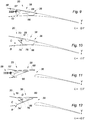
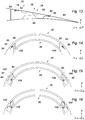
- FIGS. 6 to 16 represent the hood 20 of the nacelle 10 according to a second embodiment of the invention.
- the leakage door 38 is pivotally mounted on the cover 20 between a closed position shown in FIG. figures 6 , 9 and 10 , in which the door 38 cooperates with the associated opening 36 to oppose the flow of the air flow through the opening 36, and an open leakage position shown in FIGS. figure 7, 8 , 11 and 12 wherein the door 38 is retracted to allow flow of a portion of the airflow through the opening 36.
- the airflow is represented by arrows at Figures 6 to 8 .
- the leak gate 38 has a skin internal 66, an outer skin 68 and a slide 70 which connects the inner skin 66 and the outer skin 68 between them slidably.
- the inner skin 66 and the outer skin 68 are pivotally mounted on the cover 20 about an axis B and a C axis respectively, the B and C axes being perpendicular to the axis A of the nacelle 10 and offset between them , the pivot axis B of the inner skin 66 being radially closer to the central axis A of the nacelle 10 than the pivot axis C of the outer skin 68, as can be seen in FIG. figure 10 .
- the inner skin 66 has an upstream portion 72 which is pivotally mounted on the actuating rod 62 of the actuator 58.
- the inner skin 66 has a guide rail 74 which extends towards the outer skin 68 and which is slidably mounted in the slideway 70 provided for this purpose.
- the slideway 70 is equipped with a pivoting head 76 which is pivotally mounted on the outer skin 68, so that the slideway 70 is pivotally articulated on the outer skin 68 about an axis D perpendicular to the outside.
- axis A of the nacelle 10 and parallel to the axes B and C pivoting of the inner skin 66 and the outer skin 68 respectively.
- the rod 62 of the actuator 58 is driven forwardly or upstream of the nacelle 10 so that the inner skin 66 pivots about its pivot axis B.
- Such a mechanism allows the outer skin 68 to have an opening angle smaller than that of the inner skin 66 to limit the overflow of the outer skin 68 outside the nacelle 10 when the leakage door 38 occupies its position open, in order to limit the aerodynamic disturbances outside the nacelle 10.
- the door 38 is equipped with a first upstream seal 78 and a second seal 80 downstream type O-ring, forming a sealing means between the door 38 and the associated opening 36 of the cover 20, when the door 38 occupies its closed position.
- the first upstream gasket 78 is interposed between an upstream end portion 82 of the outer skin 68 of the door 38, and an outer casing 84 of the cap 20.
- the second downstream seal 80 is interposed between a downstream portion 86 of the outer skin 68 of the door 38 and the outer casing 84 of the cap 20.
- the leakage door 38 is equipped with a lateral sealing means between the door 38 and the associated opening 36 of the cover 20, to prevent lateral air leaks, or transversal, that is to say according to a direction perpendicular to the axis A of the nacelle 10, between the door 38 and the associated opening 36, when the door 38 occupies its closed position.
- the lateral sealing means comprises a first seal 88 which is interposed between a first longitudinal side edge 90 of the door 38 and a first longitudinal complementary side edge 92 of the outer casing 84 of the cap 20.
- the lateral sealing means comprises a second seal 94 which is interposed between a second longitudinal side edge 96 of the door 38 and a second longitudinal complementary side edge 98 of the outer casing 84 of the cover 20.
- the door 38 has a first sealing strip 102 which extends from the first longitudinal side edge 90 of the door 38, to the first side edge 92 of the outer casing 84 of the cover 20, to prevent leaks of side air between the door 38 and the associated opening 36.
- the door 38 includes a second sealing strip 104 which extends from the second longitudinal side edge 96 of the door 38, to the second side edge 98 of the outer casing 84 of the cover 20.
- the first sealing strip 102 is fixed on the first longitudinal side edge 90 of the door 38 and on the first lateral edge 92 of the outer casing 84 of the cover 20, so that the first sealing strip 102 forms a bib, or a veil, to prevent the flow of air on the sides of the door 38, to promote a longitudinal axial flow of air through the opening 36 when the door 38 is open, conducive to performance thrust of the basket 10.
- the first sealing strip is made of elastically deformable material, such as an elastomer.
- the second sealing strip 104 is fixed on the second longitudinal lateral edge 96 of the door 38 and on the second lateral edge 98 of the outer casing 84 of the cover 20.
- rigid lateral flaps 106 are arranged on each side of the door 38, as can be seen in FIG. Figures 14 to 16 .
- the invention also applies to a nacelle comprising a thrust reversal device with so-called "fixed" deflection grilles 22.
- the invention is not limited to a cover 20 defining four openings 36, the opening number may for example be six.
- this type of thrust reversing device with fixed grilles provides a smaller space for accommodating the trailing gates, it will preferably be associated with the second embodiment of the invention according to which the trailing door 38 is pivotable and requires only a reduced space of travel in the hood 20.
Landscapes
- Engineering & Computer Science (AREA)
- Chemical & Material Sciences (AREA)
- Combustion & Propulsion (AREA)
- Mechanical Engineering (AREA)
- General Engineering & Computer Science (AREA)
- Aviation & Aerospace Engineering (AREA)
- Wind Motors (AREA)
Claims (7)
- Gondel (10) für Flugzeugmotor der Art, umfassend:- eine Haube (20) zur Schubumkehr, umfassend einen vorgelagerten Abdeckungsabschnitt (28) und einen nachgelagerten Rohrabschnitt (30), wobei die Haube (20) gleitend gemäß einer Richtung montiert ist, die im Allgemeinen parallel zur Längsachse (A) der Gondel (10) ist, zwischen einer Position des direkten Strahls, in der die Haube (20) die Mittel zur Umleitung des Luftflusses abdeckt, und einer Position des umgekehrten Strahls, in der die Haube (20) einen Durchgang in der Gondel (10) öffnet und die Mittel zur Umleitung aufdeckt, und- ein Mittel zum Bewegungsantrieb der Haube (20), umfassend mindestens eine Betätigungsvorrichtung (58),- mindestens eine Öffnung (36), die durch den Rohrabschnitt (30) der Haube (20) begrenzt ist und die mit einem Ausgangstor (38) assoziiert ist, wobei das Ausgangstor (38) beweglich auf der Haube (20) zwischen einer geschlossenen Position, in der das Tor (38) mit der assoziierten Öffnung (36) zusammenarbeitet, um sich der Strömung des Luftflusses durch die Öffnung (36) entgegenzusetzen, und einer offenen Ausgangsposition montiert ist, in der das Tor (38) zurückgezogen ist, um die Strömung eines Teils des Luftflusses durch die Öffnung (36) zu ermöglichen,dadurch gekennzeichnet, dass das Ausgangstor (38) ausgewählt ist aus der Gruppe, umfassend ein Ausgangstor (38), das gleitend zwischen seiner geschlossenen und seiner offenen Position montiert ist, gemäß einer Richtung, die im Allgemeinen parallel zur Achse (A) der Gondel (10) ist, und ein Ausgangstor (38), das schwenkbar zwischen seiner geschlossenen Position und seiner offenen Position um eine Achse montiert ist, die im Wesentlichen senkrecht zur Achse (A) der Gondel (10) ist, wobei das schwenkbare Ausgangstor (38) Folgendes umfasst:- eine Innenhaut (66), die schwenkbar auf einem festen Teil der Gondel (10) montiert ist, und- eine Außenhaut (68), die sich gegenüber der Innenhaut (66) erstreckt, und die schwenkbar auf einem festen Teil der Gondel (10) montiert ist, wobei die Außenhaut (68) einen Öffnungswinkel aufweist, der geringer als derjenige der Innenhaut (66) ist, um die aerodynamischen Störungen an der Außenseite der Gondel (10) zu begrenzen, wenn das Ausgangstor (38) seine offene Position einnimmt.
- Gondel (10) für Flugzeugmotor nach Anspruch 1, dadurch gekennzeichnet, dass sie mit einem Mittel zur Verriegelung des Ausgangstors (38) auf der beweglichen Haube (20) ausgestattet ist, wobei das Mittel zur Verriegelung entworfen ist, um einen entriegelten Zustand einzunehmen, in dem das Ausgangstor (38) von der Haube (20) gelöst ist, und einen verriegelten Zustand, in dem das Ausgangstor (38) auf der Haube (20) verriegelt ist, so dass das Ausgangstor (38) und die Haube (20) ausgelegt sind, um gleichzeitig durch die Betätigungsvorrichtung (58) in Bewegung angetrieben zu werden.
- Gondel (10) für Flugzeugmotor nach einem der vorhergehenden Ansprüche, dadurch gekennzeichnet, dass das Tor (38) eine äußere Seite (42) aufweist, die entworfen ist, um die äußere aerodynamische Güte der Stromlinienverkleidung der Gondel (10) sicherzustellen, und eine innere Seite (44), die entworfen ist, um die innere aerodynamische Güte der Gondel (10) sicherzustellen, wenn das Tor (38) seine geschlossene Position einnimmt.
- Gondel (10) für Flugzeugmotor nach einem der vorhergehenden Ansprüche, dadurch gekennzeichnet, dass sie Dichtungsmittel umfasst, die entworfen sind, um sich der Strömung der Luft durch die Öffnung (36) entgegenzusetzen, wenn das Ausgangstor (38) seine Verschlussposition einnimmt.
- Gondel (10) für Flugzeugmotor nach einem der vorhergehenden Ansprüche, dadurch gekennzeichnet, dass der vorgelagerte Abdeckungsabschnitt (28) und der nachgelagerte Rohrabschnitt (30) der Haube (20) einstückig durchgeführt sind.
- Gondel (10) für Flugzeugmotor nach einem der vorhergehenden Ansprüche, dadurch gekennzeichnet, dass die Betätigungsvorrichtung (58) einen vorgelagerten Körper (60) umfasst, der mit einem festen Teil der Gondel (10) fest verbunden ist, und einen nachgelagerten Betätigungsschaft (62), der gleitend in dem assoziierten Körper (60) gemäß einer im Allgemeinen parallelen Achse zur Achse (A) der Gondel (10) montiert ist, und der auf dem Ausgangstor (38) verbunden ist, um das Ausgangstor (38) in Bewegung anzutreiben.
- Gondel (10) für Flugzeugmotor nach einem der vorhergehenden Ansprüche, dadurch gekennzeichnet, dass die Haube (20) eine Vielzahl von Öffnung (36) begrenzt, die auf kreisförmige Weise um die Längsachse (A) der Gondel (10) verteilt sind, und die jeweils mit einem beweglichen Ausgangstor (38) assoziiert sind.
Applications Claiming Priority (2)
| Application Number | Priority Date | Filing Date | Title |
|---|---|---|---|
| FR1359896A FR3011820B1 (fr) | 2013-10-11 | 2013-10-11 | Nacelle pour moteur d'aeronef a tuyere de section variable |
| PCT/FR2014/052595 WO2015052457A1 (fr) | 2013-10-11 | 2014-10-13 | Nacelle pour moteur d'aéronef à tuyère de section variable |
Publications (2)
| Publication Number | Publication Date |
|---|---|
| EP3055209A1 EP3055209A1 (de) | 2016-08-17 |
| EP3055209B1 true EP3055209B1 (de) | 2017-09-06 |
Family
ID=49876850
Family Applications (1)
| Application Number | Title | Priority Date | Filing Date |
|---|---|---|---|
| EP14799506.2A Active EP3055209B1 (de) | 2013-10-11 | 2014-10-13 | Flugzeugtriebwerksgondel mit verstellbarem düsenabschnitt |
Country Status (4)
| Country | Link |
|---|---|
| US (1) | US10619598B2 (de) |
| EP (1) | EP3055209B1 (de) |
| FR (1) | FR3011820B1 (de) |
| WO (1) | WO2015052457A1 (de) |
Families Citing this family (12)
| Publication number | Priority date | Publication date | Assignee | Title |
|---|---|---|---|---|
| FR3021704B1 (fr) | 2014-05-30 | 2016-06-03 | Aircelle Sa | Nacelle pour turboreacteur d'aeronef comprenant une tuyere secondaire a portes rotatives |
| FR3047522B1 (fr) * | 2016-02-04 | 2018-03-16 | Safran Aircraft Engines | Ensemble propulsif pour aeronef |
| US10724475B2 (en) * | 2016-09-27 | 2020-07-28 | The Boeing Company | Dual turn thrust reverser cascade systems and methods |
| US10543927B2 (en) * | 2016-11-18 | 2020-01-28 | Rohr, Inc. | Lockable track system for a translating nacelle structure |
| FR3075274B1 (fr) * | 2017-12-14 | 2021-10-22 | Airbus Operations Sas | Turboreacteur d'aeronef comportant des moyens permettant de varier sa surface de sortie |
| FR3076865B1 (fr) * | 2018-01-18 | 2020-01-03 | Safran Nacelles | Ensemble arriere d'une nacelle de turboreacteur d'aeronef comprenant un inverseur de poussee a grilles coulissantes |
| FR3090580B1 (fr) * | 2018-12-20 | 2020-11-27 | Safran | Systeme propulsif pour un aeronef |
| FR3095016B1 (fr) * | 2019-04-09 | 2021-04-16 | Airbus Operations Sas | TURBOREACTEUR DOUBLE FLUX COMPORTANT UNE PORTE DE BLOCAGE MISE EN MOUVEMENT PAR UNE BIELLE TRAVERSANT une veine SECONDAIRE |
| US11066179B2 (en) * | 2019-09-09 | 2021-07-20 | Rohr, Inc | Fire seal assembly for nacelle doors |
| FR3107932B1 (fr) * | 2020-03-09 | 2022-08-12 | Safran Aircraft Engines | Sortie d’air de nacelle pour turboréacteur d’aéronef à double flux comprenant un dispositif de guidage pour favoriser une phase d’inversion de poussée |
| CN118518252A (zh) * | 2023-02-17 | 2024-08-20 | 空中客车运营简化股份公司 | 压力测量耙、包括压力测量耙的发动机和包括发动机的飞行器 |
| US12071911B1 (en) * | 2023-06-02 | 2024-08-27 | Honeywell International Inc. | Thrust reverser for aerial vehicle |
Family Cites Families (21)
| Publication number | Priority date | Publication date | Assignee | Title |
|---|---|---|---|---|
| US3095697A (en) * | 1956-02-07 | 1963-07-02 | Boeing Co | Noise suppression nozzles with thrust reversal provision for jet engines |
| US3036431A (en) * | 1959-09-08 | 1962-05-29 | Boeing Co | Thrust reverser for jet engines |
| GB978462A (en) * | 1963-10-28 | 1964-12-23 | Rolls Royce | Gas turbine by-pass engine |
| GB1211923A (en) * | 1968-08-30 | 1970-11-11 | Rolls Royce | Thrust reverser for gas turbine jet propulsion engine |
| US3779010A (en) * | 1972-08-17 | 1973-12-18 | Gen Electric | Combined thrust reversing and throat varying mechanism for a gas turbine engine |
| US3990530A (en) * | 1975-05-19 | 1976-11-09 | United Technologies Corporation | Noise suppressor for turbine type power plant |
| GB2182724B (en) * | 1985-10-08 | 1988-12-07 | Rolls Royce | Gas turbine engine thrust reverser |
| FR2622929A1 (fr) | 1987-11-05 | 1989-05-12 | Hispano Suiza Sa | Inverseur de poussee de turboreacteur a grilles,a section variable d'ejection |
| FR2676779B1 (fr) * | 1991-05-21 | 1994-06-03 | Lair Jean Pierre | Tuyere a section variable. |
| US5516061A (en) * | 1994-09-19 | 1996-05-14 | Lockheed Corporation | Shroud for a reversible thrust fan |
| US5575147A (en) * | 1994-12-22 | 1996-11-19 | United Technologies Corporation | Compact thrust reverser |
| US5623820A (en) * | 1995-02-03 | 1997-04-29 | The Boeing Company | Flow control apparatus for gas turbine engine installation pressure relief doors |
| EP0852290A1 (de) * | 1996-12-19 | 1998-07-08 | SOCIETE DE CONSTRUCTION DES AVIONS HUREL-DUBOIS (société anonyme) | Schubumkehrvorrichtung für ein Bläsertriebwerk |
| FR2910937B1 (fr) * | 2007-01-02 | 2009-04-03 | Airbus France Sas | Nacelle de reacteur d'aeronef et aeronef comportant une telle nacelle |
| CN101939528B (zh) * | 2007-08-08 | 2013-07-24 | 罗尔股份有限公司 | 具有旁通流的面积可调风扇喷嘴 |
| FR2934326A1 (fr) * | 2008-07-28 | 2010-01-29 | Aircelle Sa | Dispositif d'inversion de poussee |
| FR2946696B1 (fr) * | 2009-06-10 | 2012-04-20 | Aircelle Sa | Dispositif d'inversion de poussee |
| FR2965304B1 (fr) * | 2010-09-23 | 2012-10-12 | Airbus Operations Sas | Dispositif de decharge d'air pour turboreacteur d'avion a double flux |
| FR2978800B1 (fr) * | 2011-08-05 | 2014-05-23 | Aircelle Sa | Nacelle de turboreacteur a tuyere variable |
| DE102015206985A1 (de) * | 2015-04-17 | 2016-10-20 | Rolls-Royce Deutschland Ltd & Co Kg | Triebwerksverkleidung einer Fluggasturbine |
| US20170030296A1 (en) * | 2015-07-28 | 2017-02-02 | Rohr, Inc. | Thrust reverser providing increased blocker door leakage |
-
2013
- 2013-10-11 FR FR1359896A patent/FR3011820B1/fr active Active
-
2014
- 2014-10-13 EP EP14799506.2A patent/EP3055209B1/de active Active
- 2014-10-13 WO PCT/FR2014/052595 patent/WO2015052457A1/fr not_active Ceased
-
2016
- 2016-04-08 US US15/093,805 patent/US10619598B2/en not_active Expired - Fee Related
Also Published As
| Publication number | Publication date |
|---|---|
| US20160222917A1 (en) | 2016-08-04 |
| WO2015052457A1 (fr) | 2015-04-16 |
| FR3011820B1 (fr) | 2017-03-31 |
| US10619598B2 (en) | 2020-04-14 |
| FR3011820A1 (fr) | 2015-04-17 |
| EP3055209A1 (de) | 2016-08-17 |
Similar Documents
| Publication | Publication Date | Title |
|---|---|---|
| WO2015052457A1 (fr) | Nacelle pour moteur d'aéronef à tuyère de section variable | |
| EP2129901B1 (de) | Schubumkehreinheit für ein düsentriebwerk | |
| EP2773861B1 (de) | Schubumkehrvorrichtung mit einteiliger mobiler haube | |
| CA2225608C (fr) | Inverseur de poussee de turboreacteur a double flux a coquilles aval | |
| EP2433864B1 (de) | Vorrichtung zum Ableiten von Luft für ein Zweistromturbotriebwerk eines Flugzeugs | |
| EP2737231B1 (de) | Doppeltwirkender linearantrieb | |
| EP3129631B1 (de) | Schubumkehrvorrichtung mit schwenkklappen für eine flugzeug-turbostrahl-triebwerksgondel | |
| EP2742228A1 (de) | Schubumkehrvorrichtung | |
| EP3149318B1 (de) | Gondel für ein turbojet-triebwerk mit einem sekundärdüsenabschnitt mit drehtüren | |
| EP3740666B1 (de) | Hintere baugruppe einer triebwerksgondel eines luftfahrzeugs mit gleitender kaskadenschubumkehrvorrichtung | |
| EP3164589B1 (de) | Turbostrahlgondel mit einer schubumkehrvorrichtung mit ausstanzungen zur vermeidung der beweglichen lamelle eines flugzeugflügels | |
| EP3155252B1 (de) | Schubumkehrer für gondel eines flugzeugturbofans | |
| FR2962492A1 (fr) | Dispositif d'inversion de poussee avec jonction aerodynamique de cadre avant | |
| WO2015001276A1 (fr) | Nacelle de turboréacteur à tuyère variable | |
| EP3768960B1 (de) | Turbolüfterantriebsanordnung mit schubumkehrer mit beweglichen leitschaufeln | |
| WO2012045965A1 (fr) | Ensemble propulsif d'aéronef | |
| EP3488094B1 (de) | System zur betätigung einer platte einer turbostrahltriebwerksgondel | |
| FR3038587A1 (fr) | Nacelle de turboreacteur d’aeronef, ensemble propulsif comportant une nacelle, et aeronef comportant au moins un ensemble propulsif | |
| CA2887470A1 (fr) | Nacelle pour turboreacteur comprenant un ensemble unitaire mobile le long d'un ensemble de guidage | |
| FR3010145A1 (fr) | Inverseur de poussee d’une nacelle de turboreacteur, comprenant des grilles et des verins fixes a l’amont des capots mobiles | |
| WO2015145056A1 (fr) | Dispositif d'inversion de poussée sans grille pour nacelle de turboréacteur d'aéronef | |
| WO2018015672A1 (fr) | Nacelle pour turboréacteur double flux à soufflante à calage variable et ensemble propulsif comportant une telle nacelle | |
| WO2009060133A2 (fr) | Actionneur lineaire telescopique double action | |
| EP3963201B1 (de) | Schubumkehrer mit beweglicher haube mit schubreduzierungsmechanismus, der unabhängig von der beweglichen haube ist | |
| WO2014195646A1 (fr) | Inverseur de poussée d'une nacelle de turboréacteur, comprenant des grilles fixées aux capots mobiles |
Legal Events
| Date | Code | Title | Description |
|---|---|---|---|
| PUAI | Public reference made under article 153(3) epc to a published international application that has entered the european phase |
Free format text: ORIGINAL CODE: 0009012 |
|
| 17P | Request for examination filed |
Effective date: 20160413 |
|
| AK | Designated contracting states |
Kind code of ref document: A1 Designated state(s): AL AT BE BG CH CY CZ DE DK EE ES FI FR GB GR HR HU IE IS IT LI LT LU LV MC MK MT NL NO PL PT RO RS SE SI SK SM TR |
|
| AX | Request for extension of the european patent |
Extension state: BA ME |
|
| REG | Reference to a national code |
Ref country code: DE Ref legal event code: R079 Ref document number: 602014014338 Country of ref document: DE Free format text: PREVIOUS MAIN CLASS: B64D0033040000 Ipc: F02K0001090000 |
|
| DAX | Request for extension of the european patent (deleted) | ||
| RAP1 | Party data changed (applicant data changed or rights of an application transferred) |
Owner name: SAFRAN NACELLES |
|
| RIC1 | Information provided on ipc code assigned before grant |
Ipc: B64D 33/04 20060101ALI20170112BHEP Ipc: F02K 1/09 20060101AFI20170112BHEP Ipc: F02K 1/72 20060101ALI20170112BHEP Ipc: F02K 1/76 20060101ALI20170112BHEP Ipc: F02K 1/12 20060101ALI20170112BHEP |
|
| GRAP | Despatch of communication of intention to grant a patent |
Free format text: ORIGINAL CODE: EPIDOSNIGR1 |
|
| INTG | Intention to grant announced |
Effective date: 20170426 |
|
| GRAS | Grant fee paid |
Free format text: ORIGINAL CODE: EPIDOSNIGR3 |
|
| GRAA | (expected) grant |
Free format text: ORIGINAL CODE: 0009210 |
|
| AK | Designated contracting states |
Kind code of ref document: B1 Designated state(s): AL AT BE BG CH CY CZ DE DK EE ES FI FR GB GR HR HU IE IS IT LI LT LU LV MC MK MT NL NO PL PT RO RS SE SI SK SM TR |
|
| REG | Reference to a national code |
Ref country code: GB Ref legal event code: FG4D Free format text: NOT ENGLISH |
|
| REG | Reference to a national code |
Ref country code: CH Ref legal event code: EP Ref country code: AT Ref legal event code: REF Ref document number: 926168 Country of ref document: AT Kind code of ref document: T Effective date: 20170915 |
|
| REG | Reference to a national code |
Ref country code: IE Ref legal event code: FG4D Free format text: LANGUAGE OF EP DOCUMENT: FRENCH |
|
| REG | Reference to a national code |
Ref country code: FR Ref legal event code: PLFP Year of fee payment: 4 |
|
| REG | Reference to a national code |
Ref country code: DE Ref legal event code: R096 Ref document number: 602014014338 Country of ref document: DE |
|
| REG | Reference to a national code |
Ref country code: NL Ref legal event code: MP Effective date: 20170906 |
|
| REG | Reference to a national code |
Ref country code: LT Ref legal event code: MG4D |
|
| PG25 | Lapsed in a contracting state [announced via postgrant information from national office to epo] |
Ref country code: HR Free format text: LAPSE BECAUSE OF FAILURE TO SUBMIT A TRANSLATION OF THE DESCRIPTION OR TO PAY THE FEE WITHIN THE PRESCRIBED TIME-LIMIT Effective date: 20170906 Ref country code: FI Free format text: LAPSE BECAUSE OF FAILURE TO SUBMIT A TRANSLATION OF THE DESCRIPTION OR TO PAY THE FEE WITHIN THE PRESCRIBED TIME-LIMIT Effective date: 20170906 Ref country code: NO Free format text: LAPSE BECAUSE OF FAILURE TO SUBMIT A TRANSLATION OF THE DESCRIPTION OR TO PAY THE FEE WITHIN THE PRESCRIBED TIME-LIMIT Effective date: 20171206 Ref country code: LT Free format text: LAPSE BECAUSE OF FAILURE TO SUBMIT A TRANSLATION OF THE DESCRIPTION OR TO PAY THE FEE WITHIN THE PRESCRIBED TIME-LIMIT Effective date: 20170906 Ref country code: SE Free format text: LAPSE BECAUSE OF FAILURE TO SUBMIT A TRANSLATION OF THE DESCRIPTION OR TO PAY THE FEE WITHIN THE PRESCRIBED TIME-LIMIT Effective date: 20170906 |
|
| REG | Reference to a national code |
Ref country code: AT Ref legal event code: MK05 Ref document number: 926168 Country of ref document: AT Kind code of ref document: T Effective date: 20170906 |
|
| PG25 | Lapsed in a contracting state [announced via postgrant information from national office to epo] |
Ref country code: LV Free format text: LAPSE BECAUSE OF FAILURE TO SUBMIT A TRANSLATION OF THE DESCRIPTION OR TO PAY THE FEE WITHIN THE PRESCRIBED TIME-LIMIT Effective date: 20170906 Ref country code: GR Free format text: LAPSE BECAUSE OF FAILURE TO SUBMIT A TRANSLATION OF THE DESCRIPTION OR TO PAY THE FEE WITHIN THE PRESCRIBED TIME-LIMIT Effective date: 20171207 Ref country code: BG Free format text: LAPSE BECAUSE OF FAILURE TO SUBMIT A TRANSLATION OF THE DESCRIPTION OR TO PAY THE FEE WITHIN THE PRESCRIBED TIME-LIMIT Effective date: 20171206 Ref country code: RS Free format text: LAPSE BECAUSE OF FAILURE TO SUBMIT A TRANSLATION OF THE DESCRIPTION OR TO PAY THE FEE WITHIN THE PRESCRIBED TIME-LIMIT Effective date: 20170906 Ref country code: ES Free format text: LAPSE BECAUSE OF FAILURE TO SUBMIT A TRANSLATION OF THE DESCRIPTION OR TO PAY THE FEE WITHIN THE PRESCRIBED TIME-LIMIT Effective date: 20170906 |
|
| PG25 | Lapsed in a contracting state [announced via postgrant information from national office to epo] |
Ref country code: NL Free format text: LAPSE BECAUSE OF FAILURE TO SUBMIT A TRANSLATION OF THE DESCRIPTION OR TO PAY THE FEE WITHIN THE PRESCRIBED TIME-LIMIT Effective date: 20170906 |
|
| PG25 | Lapsed in a contracting state [announced via postgrant information from national office to epo] |
Ref country code: PL Free format text: LAPSE BECAUSE OF FAILURE TO SUBMIT A TRANSLATION OF THE DESCRIPTION OR TO PAY THE FEE WITHIN THE PRESCRIBED TIME-LIMIT Effective date: 20170906 Ref country code: CZ Free format text: LAPSE BECAUSE OF FAILURE TO SUBMIT A TRANSLATION OF THE DESCRIPTION OR TO PAY THE FEE WITHIN THE PRESCRIBED TIME-LIMIT Effective date: 20170906 Ref country code: RO Free format text: LAPSE BECAUSE OF FAILURE TO SUBMIT A TRANSLATION OF THE DESCRIPTION OR TO PAY THE FEE WITHIN THE PRESCRIBED TIME-LIMIT Effective date: 20170906 |
|
| REG | Reference to a national code |
Ref country code: DE Ref legal event code: R119 Ref document number: 602014014338 Country of ref document: DE |
|
| PG25 | Lapsed in a contracting state [announced via postgrant information from national office to epo] |
Ref country code: SK Free format text: LAPSE BECAUSE OF FAILURE TO SUBMIT A TRANSLATION OF THE DESCRIPTION OR TO PAY THE FEE WITHIN THE PRESCRIBED TIME-LIMIT Effective date: 20170906 Ref country code: EE Free format text: LAPSE BECAUSE OF FAILURE TO SUBMIT A TRANSLATION OF THE DESCRIPTION OR TO PAY THE FEE WITHIN THE PRESCRIBED TIME-LIMIT Effective date: 20170906 Ref country code: IS Free format text: LAPSE BECAUSE OF FAILURE TO SUBMIT A TRANSLATION OF THE DESCRIPTION OR TO PAY THE FEE WITHIN THE PRESCRIBED TIME-LIMIT Effective date: 20180106 Ref country code: IT Free format text: LAPSE BECAUSE OF FAILURE TO SUBMIT A TRANSLATION OF THE DESCRIPTION OR TO PAY THE FEE WITHIN THE PRESCRIBED TIME-LIMIT Effective date: 20170906 Ref country code: AT Free format text: LAPSE BECAUSE OF FAILURE TO SUBMIT A TRANSLATION OF THE DESCRIPTION OR TO PAY THE FEE WITHIN THE PRESCRIBED TIME-LIMIT Effective date: 20170906 Ref country code: SM Free format text: LAPSE BECAUSE OF FAILURE TO SUBMIT A TRANSLATION OF THE DESCRIPTION OR TO PAY THE FEE WITHIN THE PRESCRIBED TIME-LIMIT Effective date: 20170906 |
|
| REG | Reference to a national code |
Ref country code: CH Ref legal event code: PL |
|
| PG25 | Lapsed in a contracting state [announced via postgrant information from national office to epo] |
Ref country code: MC Free format text: LAPSE BECAUSE OF FAILURE TO SUBMIT A TRANSLATION OF THE DESCRIPTION OR TO PAY THE FEE WITHIN THE PRESCRIBED TIME-LIMIT Effective date: 20170906 |
|
| PLBE | No opposition filed within time limit |
Free format text: ORIGINAL CODE: 0009261 |
|
| STAA | Information on the status of an ep patent application or granted ep patent |
Free format text: STATUS: NO OPPOSITION FILED WITHIN TIME LIMIT |
|
| REG | Reference to a national code |
Ref country code: IE Ref legal event code: MM4A |
|
| PG25 | Lapsed in a contracting state [announced via postgrant information from national office to epo] |
Ref country code: LU Free format text: LAPSE BECAUSE OF NON-PAYMENT OF DUE FEES Effective date: 20171013 Ref country code: DK Free format text: LAPSE BECAUSE OF FAILURE TO SUBMIT A TRANSLATION OF THE DESCRIPTION OR TO PAY THE FEE WITHIN THE PRESCRIBED TIME-LIMIT Effective date: 20170906 Ref country code: LI Free format text: LAPSE BECAUSE OF NON-PAYMENT OF DUE FEES Effective date: 20171031 Ref country code: CH Free format text: LAPSE BECAUSE OF NON-PAYMENT OF DUE FEES Effective date: 20171031 Ref country code: DE Free format text: LAPSE BECAUSE OF NON-PAYMENT OF DUE FEES Effective date: 20180501 |
|
| 26N | No opposition filed |
Effective date: 20180607 |
|
| REG | Reference to a national code |
Ref country code: BE Ref legal event code: MM Effective date: 20171031 |
|
| PG25 | Lapsed in a contracting state [announced via postgrant information from national office to epo] |
Ref country code: BE Free format text: LAPSE BECAUSE OF NON-PAYMENT OF DUE FEES Effective date: 20171031 Ref country code: SI Free format text: LAPSE BECAUSE OF FAILURE TO SUBMIT A TRANSLATION OF THE DESCRIPTION OR TO PAY THE FEE WITHIN THE PRESCRIBED TIME-LIMIT Effective date: 20170906 |
|
| PG25 | Lapsed in a contracting state [announced via postgrant information from national office to epo] |
Ref country code: MT Free format text: LAPSE BECAUSE OF FAILURE TO SUBMIT A TRANSLATION OF THE DESCRIPTION OR TO PAY THE FEE WITHIN THE PRESCRIBED TIME-LIMIT Effective date: 20170906 |
|
| REG | Reference to a national code |
Ref country code: FR Ref legal event code: PLFP Year of fee payment: 5 |
|
| PG25 | Lapsed in a contracting state [announced via postgrant information from national office to epo] |
Ref country code: IE Free format text: LAPSE BECAUSE OF NON-PAYMENT OF DUE FEES Effective date: 20171013 |
|
| PG25 | Lapsed in a contracting state [announced via postgrant information from national office to epo] |
Ref country code: HU Free format text: LAPSE BECAUSE OF FAILURE TO SUBMIT A TRANSLATION OF THE DESCRIPTION OR TO PAY THE FEE WITHIN THE PRESCRIBED TIME-LIMIT; INVALID AB INITIO Effective date: 20141013 |
|
| PG25 | Lapsed in a contracting state [announced via postgrant information from national office to epo] |
Ref country code: CY Free format text: LAPSE BECAUSE OF FAILURE TO SUBMIT A TRANSLATION OF THE DESCRIPTION OR TO PAY THE FEE WITHIN THE PRESCRIBED TIME-LIMIT Effective date: 20170906 |
|
| PG25 | Lapsed in a contracting state [announced via postgrant information from national office to epo] |
Ref country code: MK Free format text: LAPSE BECAUSE OF FAILURE TO SUBMIT A TRANSLATION OF THE DESCRIPTION OR TO PAY THE FEE WITHIN THE PRESCRIBED TIME-LIMIT Effective date: 20170906 |
|
| PG25 | Lapsed in a contracting state [announced via postgrant information from national office to epo] |
Ref country code: TR Free format text: LAPSE BECAUSE OF FAILURE TO SUBMIT A TRANSLATION OF THE DESCRIPTION OR TO PAY THE FEE WITHIN THE PRESCRIBED TIME-LIMIT Effective date: 20170906 |
|
| PG25 | Lapsed in a contracting state [announced via postgrant information from national office to epo] |
Ref country code: PT Free format text: LAPSE BECAUSE OF FAILURE TO SUBMIT A TRANSLATION OF THE DESCRIPTION OR TO PAY THE FEE WITHIN THE PRESCRIBED TIME-LIMIT Effective date: 20170906 |
|
| PG25 | Lapsed in a contracting state [announced via postgrant information from national office to epo] |
Ref country code: AL Free format text: LAPSE BECAUSE OF FAILURE TO SUBMIT A TRANSLATION OF THE DESCRIPTION OR TO PAY THE FEE WITHIN THE PRESCRIBED TIME-LIMIT Effective date: 20170906 |
|
| PGFP | Annual fee paid to national office [announced via postgrant information from national office to epo] |
Ref country code: GB Payment date: 20200921 Year of fee payment: 7 |
|
| GBPC | Gb: european patent ceased through non-payment of renewal fee |
Effective date: 20211013 |
|
| PG25 | Lapsed in a contracting state [announced via postgrant information from national office to epo] |
Ref country code: GB Free format text: LAPSE BECAUSE OF NON-PAYMENT OF DUE FEES Effective date: 20211013 |
|
| PGFP | Annual fee paid to national office [announced via postgrant information from national office to epo] |
Ref country code: FR Payment date: 20251024 Year of fee payment: 12 |