EP3055573B1 - Machine fluidique pouvant être opérée comme moteur hydraulique ou comme pompe - Google Patents
Machine fluidique pouvant être opérée comme moteur hydraulique ou comme pompe Download PDFInfo
- Publication number
- EP3055573B1 EP3055573B1 EP14809757.9A EP14809757A EP3055573B1 EP 3055573 B1 EP3055573 B1 EP 3055573B1 EP 14809757 A EP14809757 A EP 14809757A EP 3055573 B1 EP3055573 B1 EP 3055573B1
- Authority
- EP
- European Patent Office
- Prior art keywords
- drive
- pressure
- piston
- turbo machine
- distributor
- Prior art date
- Legal status (The legal status is an assumption and is not a legal conclusion. Google has not performed a legal analysis and makes no representation as to the accuracy of the status listed.)
- Active
Links
Images

Classifications
-
- F—MECHANICAL ENGINEERING; LIGHTING; HEATING; WEAPONS; BLASTING
- F04—POSITIVE - DISPLACEMENT MACHINES FOR LIQUIDS; PUMPS FOR LIQUIDS OR ELASTIC FLUIDS
- F04C—ROTARY-PISTON, OR OSCILLATING-PISTON, POSITIVE-DISPLACEMENT MACHINES FOR LIQUIDS; ROTARY-PISTON, OR OSCILLATING-PISTON, POSITIVE-DISPLACEMENT PUMPS
- F04C14/00—Control of, monitoring of, or safety arrangements for, machines, pumps or pumping installations
- F04C14/06—Control of, monitoring of, or safety arrangements for, machines, pumps or pumping installations specially adapted for stopping, starting, idling or no-load operation
-
- F—MECHANICAL ENGINEERING; LIGHTING; HEATING; WEAPONS; BLASTING
- F04—POSITIVE - DISPLACEMENT MACHINES FOR LIQUIDS; PUMPS FOR LIQUIDS OR ELASTIC FLUIDS
- F04C—ROTARY-PISTON, OR OSCILLATING-PISTON, POSITIVE-DISPLACEMENT MACHINES FOR LIQUIDS; ROTARY-PISTON, OR OSCILLATING-PISTON, POSITIVE-DISPLACEMENT PUMPS
- F04C2/00—Rotary-piston machines or pumps
- F04C2/08—Rotary-piston machines or pumps of intermeshing-engagement type, i.e. with engagement of co-operating members similar to that of toothed gearing
- F04C2/10—Rotary-piston machines or pumps of intermeshing-engagement type, i.e. with engagement of co-operating members similar to that of toothed gearing of internal-axis type with the outer member having more teeth or tooth-equivalents, e.g. rollers, than the inner member
-
- F—MECHANICAL ENGINEERING; LIGHTING; HEATING; WEAPONS; BLASTING
- F03—MACHINES OR ENGINES FOR LIQUIDS; WIND, SPRING, OR WEIGHT MOTORS; PRODUCING MECHANICAL POWER OR A REACTIVE PROPULSIVE THRUST, NOT OTHERWISE PROVIDED FOR
- F03C—POSITIVE-DISPLACEMENT ENGINES DRIVEN BY LIQUIDS
- F03C2/00—Rotary-piston engines
- F03C2/08—Rotary-piston engines of intermeshing-engagement type, i.e. with engagement of co- operating members similar to that of toothed gearing
-
- F—MECHANICAL ENGINEERING; LIGHTING; HEATING; WEAPONS; BLASTING
- F04—POSITIVE - DISPLACEMENT MACHINES FOR LIQUIDS; PUMPS FOR LIQUIDS OR ELASTIC FLUIDS
- F04B—POSITIVE-DISPLACEMENT MACHINES FOR LIQUIDS; PUMPS
- F04B49/00—Control, e.g. of pump delivery, or pump pressure of, or safety measures for, machines, pumps, or pumping installations, not otherwise provided for, or of interest apart from, groups F04B1/00 - F04B47/00
- F04B49/08—Regulating by delivery pressure
-
- F—MECHANICAL ENGINEERING; LIGHTING; HEATING; WEAPONS; BLASTING
- F04—POSITIVE - DISPLACEMENT MACHINES FOR LIQUIDS; PUMPS FOR LIQUIDS OR ELASTIC FLUIDS
- F04C—ROTARY-PISTON, OR OSCILLATING-PISTON, POSITIVE-DISPLACEMENT MACHINES FOR LIQUIDS; ROTARY-PISTON, OR OSCILLATING-PISTON, POSITIVE-DISPLACEMENT PUMPS
- F04C14/00—Control of, monitoring of, or safety arrangements for, machines, pumps or pumping installations
- F04C14/04—Control of, monitoring of, or safety arrangements for, machines, pumps or pumping installations specially adapted for reversible machines or pumps
-
- F—MECHANICAL ENGINEERING; LIGHTING; HEATING; WEAPONS; BLASTING
- F04—POSITIVE - DISPLACEMENT MACHINES FOR LIQUIDS; PUMPS FOR LIQUIDS OR ELASTIC FLUIDS
- F04C—ROTARY-PISTON, OR OSCILLATING-PISTON, POSITIVE-DISPLACEMENT MACHINES FOR LIQUIDS; ROTARY-PISTON, OR OSCILLATING-PISTON, POSITIVE-DISPLACEMENT PUMPS
- F04C2/00—Rotary-piston machines or pumps
- F04C2/08—Rotary-piston machines or pumps of intermeshing-engagement type, i.e. with engagement of co-operating members similar to that of toothed gearing
- F04C2/10—Rotary-piston machines or pumps of intermeshing-engagement type, i.e. with engagement of co-operating members similar to that of toothed gearing of internal-axis type with the outer member having more teeth or tooth-equivalents, e.g. rollers, than the inner member
- F04C2/102—Rotary-piston machines or pumps of intermeshing-engagement type, i.e. with engagement of co-operating members similar to that of toothed gearing of internal-axis type with the outer member having more teeth or tooth-equivalents, e.g. rollers, than the inner member the two members rotating simultaneously around their respective axes
-
- F—MECHANICAL ENGINEERING; LIGHTING; HEATING; WEAPONS; BLASTING
- F04—POSITIVE - DISPLACEMENT MACHINES FOR LIQUIDS; PUMPS FOR LIQUIDS OR ELASTIC FLUIDS
- F04B—POSITIVE-DISPLACEMENT MACHINES FOR LIQUIDS; PUMPS
- F04B49/00—Control, e.g. of pump delivery, or pump pressure of, or safety measures for, machines, pumps, or pumping installations, not otherwise provided for, or of interest apart from, groups F04B1/00 - F04B47/00
- F04B49/02—Stopping, starting, unloading or idling control
Definitions
- the present invention relates to a turbomachine, which can be operated both as a motor and as a pump, with an axially fixed shaft, comprising a power part and a control, which comprises at least one connection part, on which at least one distributor part with passage openings and at least one supply part are arranged are, the distributor part is driven by means of at least one drive arranged on the shaft and axial forces are distributed to a piston arranged axially on the distributor part, the at least one inlet and outlet provided on the machine part being designed to rotate and from the distributor part and the piston is supplied with at least two co-rotating drive pressures via the supply line part, the drive pressures generating forces on the piston with their associated projected annular surfaces.
- a power unit is to be understood as a machine which is supplied for operation with at least two co-rotating feed pressures and for this purpose has an output which drives the distributor part of the turbomachine.
- This can be both a controllable and a non-controllable machine.
- a hydraulic unit for providing a pressurized hydraulic fluid for driving a coupled hydraulic actuator which is equipped with a motor arranged in a pressurized motor housing, a hydraulic accumulator arranged in a storage housing and a hydraulic pump arranged in a pump housing and a hydraulic block.
- a characteristic of this is that at least the motor housing, pump housing and the hydraulic block form a single, manageable, rigid module and the hydraulic fluid flowing around the module penetrates all elements of the module in the longitudinal direction (circulation system) in areas.
- An essential element of this hydraulic unit is that the hydraulic pump and the hydraulic block form a functional unit, the hydraulic block is provided with a plurality of hydraulic connection elements and a delivery chamber arranged in the pump housing is covered by a flange through the hydraulic block on the side opposite the motor housing.
- a hydraulic device comprising a housing with a fluid supply opening and a fluid outlet opening, a rotor being provided in the housing and a stator, furthermore a rotor which is rotatable with respect to the stator and has a low pressure and a high pressure zone.
- a commutator valve is rotatably received in the housing, a high pressure and low pressure zone in connection with the fluid supply connection and the fluid discharge opening being connected in two cavities.
- Rotary piston machines which have a structural design as described at the outset, wherein the manifold parts shown therein are each subjected to pressure on the end face.
- the present invention is based on the object of creating a turbomachine in which the axial forces are very small or even zero apart from a minimum force for sealing the running surfaces, and which can be used both as a pump and as a drive machine and with all conceivable flow media can be operated, whereby they behave the same in clockwise and counterclockwise rotation and the function is to be reliably guaranteed regardless of the pressure constellations of the drive pressures.
- a flow machine of the type mentioned at the beginning is characterized in that at least one of the further pressure areas or replacement surfaces is connected to a drive to the control device through supply lines and a control device and is thereby acted upon with a control pressure and thereby the total force on the end face and the efficiency over the total resulting force, which presses the contact surfaces between piston and distributor part, and between distributor part and supply line part, is changed within a control range.
- the turbo machine should preferably be able to be designed in the two-pipe principle without a separate leakage drain and be able to be equipped with a control device and an associated drive so that it retains its high efficiency even at high pressures.
- a freewheeling function, a braking function, a blocking function, a soft start, a linearization of the characteristic curves and, within a control range, an adaptation of the characteristic curves to specific load requirements should be realizable via the control device.
- All forces acting on the distributor part are initially in equilibrium in each of the four operating states of the turbomachine, both in the axial and in the radial direction - with the exception of a sealing force.
- additional pressure areas are arranged on the distributor part in such a way that a regular and inherently symmetrical pressure distribution is formed on the end face of the distributor part.
- This balance can now be changed in a targeted manner by an additional, preferably provided control device with a drive.
- a control device is to be understood below as a force transmission means which transmits axial forces to the piston. This force is generated by a separate drive and can also be used for braking or soft starting or blocking or disengaging the turbo machine.
- turbomachine For the person skilled in the art, it was extremely astonishing that all of the above-mentioned disadvantages no longer occurred with the invented turbomachine.
- the essential and decisive advantage of the proposed turbomachine is that it is very functionally reliable in all four quadrants, has the same properties in clockwise and counterclockwise rotation and, by eliminating friction losses, achieves a significantly higher degree of efficiency and very high starting torques.
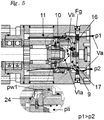
- the preferred turbomachine 1 consists of a power unit 2 and a controller 3, the power unit 2 driving the distributor part 10 via the drive 12. Via the supply part 11, the power part 2 is supplied with the two drive pressures p1, p2 with a rotating inflow and outflow.
- the distributor part 10 is arranged axially to the supply line part 11.
- the piston 9 is arranged axially on the distributor part 10 and is axially supplied with the two drive pressures p1, p2 via the connection part 4.
- Piston 9, distributor part 10 and feed line part 11 are arranged on connection part 4.
- the two connections 5, 6 are in the connection part 4.
- the control device 13 acts in the axial direction on the piston 9 and is driven by the drive of the control device 14.
- the two check valves 16, 17 are arranged between the inner leakage area 7 and the connections 5, 6.
- a spring 15 generates a spring force Ff with which the piston 9 and the distributor part 10 are pressed onto the feed line part 11 in order to seal them against one another. It is arranged between the connection part 4 and the piston 9.
- the axial and almost straight supply of the power section 2 with the drive pressures p1, p2 is particularly advantageous for the efficiency of the turbomachine 1.
- the flow of the flowable medium is hardly slowed down by deflections.
- the turbomachine 1 can also without a control device 13 with a drive for the control device 14 be executed.
- the advantage of this design is that the turbo machine 1 is much cheaper if none of the freewheeling, soft start, braking or blocking functions are required in the application, but only an inexpensive machine with excellent efficiency and the same functionally reliable behavior in clockwise and counterclockwise rotation .
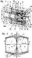
- FIG. 2 As can be seen, conventional flow machines have different characteristic curves K0 in clockwise and counterclockwise rotation. In comparison, three possible characteristic curves K1, K2, K3 of the turbo machine 1 according to the invention are shown within a control range 19. The figure shows the efficiency ⁇ over the speed of the shaft nw. At constant drive pressures p1, p2 this is roughly proportional to the torque Mw nw.
- the characteristic curve K1 shows, by way of example, the behavior of a turbomachine 1 without a control device 13.
- K1 is already almost symmetrical or even completely symmetrical in the four quadrants I-IV.
- the higher starting torque on the shaft Mw in the first two quadrants I, II when driving, or the high starting torque in the two quadrants III, IV when pumping is advantageous here. Start-up is always reliably guaranteed here even with very small pressure differences between the two drive pressures p1, p2.
- a low starting torque is important for windmills, for example, which do not only generate energy at, for example, 3 m / s wind speed, but rather already at, for example, 1 m / s wind speed.
- the characteristic curve K2 shows an example of a characteristic curve of a turbo machine 1 with control device 13 and the drive of the control device 14, in which the efficiency has been linearized in sections and optimized within the control range 19 for high pressures by applying the necessary sealing forces in the turbo machine 1 to the respective pressure conditions of the two drive pressures p1, p2 and have been adapted to the speed of the turbo machine 1.
- turbo machine 1 can now be controlled.
- its improved properties In connection with its improved properties, its more reliable function and the additional functions of freewheeling, soft start, braking and blocking, it is suitable for a variety of applications such as travel drives, windmills, measuring systems, drives in safety-critical applications or servo drives.
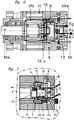
- the control plate 10 has alternating through openings 26, 27 through which the drive pressures p1, p2 can act.
- the drive pressure p1 generates the force from p1 Fp1.
- the drive pressure p2 generates the force from p2 Fp2.
- These forces Fp1, Fp2 are calculated from the drive pressures p1, p2 and the associated projected annular surfaces on the piston 9.
- the spring 15 generates the spring force Ff.
- the internal leakage pressure pli generates the force Fl with the associated projected surface.
- the control force Fs also acts.
- Various pressures act on the end face of the distributor part 10, which are also not constantly distributed.
- Fgsx becomes FgsA, FgsB, or FgsC.
- the exact pressure conditions on this surface are non-linear, speed-dependent and very complex.
- FIG Fig. 3 A segment each with a passage opening 26 for the drive pressure p1 and a passage opening 27 for the drive pressure p2 is shown in FIG Fig. 3 shown enlarged, as well as a pressure range of an internal leakage pressure pl and a further pressure pw1.
- a further advantage is based on the fact that if a control device 13 with drive 14 is present, the spring 15 can even be dispensed with if this spring force Ff is generated by the driven control device 13, 14.
- Another advantage is based on the fact that, according to the case that the piston 9 and / or the distributor part 10 and / or the control device 13 are designed magnetically, axial forces can also be generated hereby.
- a simple electromagnet, for example, can then be used as the drive for the control device 13.
- Fig. 4 the complex pressure distributions on the end faces of the distributor part 10 can be represented in a simplified manner on a model pressure curve with a non-constant gradient between the drive pressure p2 and the further pressure pw1.
- a boundary point 25 is determined such that the two areas A in the model system and in the substitute system are the same size. If this process is carried out several times at different points on a turbomachine 1, the connection of the boundary points 25 leads to the replacement areas A1, A2, A3, B1, B2, B3, B4, C1, C2, C3, C4, C5 ..., in where the respective pressure p1, pli, pw1, pw2 ... is constant.
- turbomachine 1 is now the same or the same again due to the symmetrical relationships in clockwise and counterclockwise rotation at least has almost the same properties.
- Another advantage is based on the fact that, in the event that the further pressure pw1 is equal to the internal leakage pressure pi, the structure of the turbo machine 1 is considerably simplified, since the pressure areas B3 and B4 only have to be connected by supply lines 24.
- a further pressure pw1 can also be supplied from the outside via the connection part 4 as a control pressure through at least one feed line to the further pressure area 24.
- the turbo machine 1 in an operating state as a pump or as a motor requires a total resulting force Fg which presses via the piston 9 and the distributor part 10 onto the supply line part 11 and thus the end faces of the piston 9, distributor part 10 and Supply line part 11 seals against each other.
- a pressure difference between the two drive pressures p1, p2 results in the drive current Va which drives the turbomachine 1.
- Leakage between the piston 9, distributor part 10 and supply line part 11 results in an internal leakage flow Vli and an external leakage flow Vla.
- Both leakage currents Vla, Vli are connected to one another via preferred feed lines to the further pressure area 24.
- These leakage currents Vla, Vli collect and generate the internal leakage pressure pli. As soon as this internal leakage pressure pli is large enough, it is diverted via one of the two check valves 16, 17 into the smaller of the two drive pressures p1, p2.
- Another advantage is that the distribution part 10 is supplied with almost no deflection axially via the piston 9 and the connection part 4, and the large cross-sections of the passage openings 26, 27 for the two drive pressures p1, p2 also result in very large flow cross-sections . Both contribute to a good overall efficiency ⁇ .
- turbomachine 1 is optimized in terms of production technology in all of its parts, since there are no inclined bores apart from a feed line to the further pressure region 24.
- the turbomachine 1 is brought into a freewheeling operating state when the total resulting force Fg pushes the piston 9 away from the distributor part 10.
- a force Fs is exerted on the piston 9 via a control device 13 with a drive for the control device 14.
- This creates gaps between the piston 9, the distributor part 10 and the feed line part 11 through which an internal short-circuit current Vki and an external short-circuit current Vka are formed.
- the control device 13 can advantageously be used very sensitively to transition from freewheeling to starting the machine, so that a soft start occurs.
- Another advantage is that the braking torque that arises when the freewheel is open is very low, since no internal braking torques can arise from the total resulting force Fg.
- connection 5, 6 can also be arranged directly on the piston 9.
- the spring 15 presses the distributor part 10 onto the supply line part 11 via the piston 9.
- the distributor part 10 is supplied radially from the inside with the drive pressures p1, p2.
- the axial forces Fp1, Fp2, which result from the supply pressures p1, p2, become zero.
- the control device 13 advantageously consists of a flowable medium, which is located in a cylinder which is arranged between the piston 9 and the two connection parts 4.
- the drive of the control device 14 applies a control pressure to this flowable medium and thus generates the control force Fs.
- the distributor part 10 is driven by the drive 12 of the distributor part 10 at the speed nv.
- the two check valves 16, 17 are arranged between the inner leak area 7 and the connections 5, 6.
- a further advantage of this embodiment of the turbomachine 1 is based on the fact that the entire system is operated via flowable media, thus facilitating integration into an overall system in which the control information is already available in the form of a control pressure.
- the connections 5, 6 can be arranged on the connection part 4 and supply the distributor part 10 with the drive pressures p1, pw directly and not via the piston 9. It is advantageous here that the axial forces Fp1, Fp2, which result from the supply pressures p1, p2, act radially and thus become zero axially. Pressure fluctuations of p1, p2 no longer have any influence on the total resulting force Fg.
- the spring 15 presses the distributor part 10 onto the supply part 11 via the piston 9.
- the distributor part 10 is supplied with drive pressures p1, p2 radially from the outside .
- the drive of the control device 14 exerts a control force Fs on the piston via the control device 13.
- the distributor part 10 is driven by the drive 12 of the distributor part 10 at the speed nv.
- the further pressure area is arranged on the outside of the distributor part 10.
- a separate leakage connection 18 is arranged in the connection part 4. If the flowable medium is a gaseous fluid, which enters the turbo machine 1 via the connection 5 with the drive pressure p1 and flows into the open air via the connection 6, the leakage flow Vli can also immediately flow out via the leakage connection 18, without first having to build up a pressure to control check valves 15, 16. As a result, the starting pressure p1 of the turbomachine 1 drops to an advantageous minimum.
- a further advantage of this embodiment is based on the fact that the turbo machine 1 can be built even more cheaply without check valves.
- the piston 9 is arranged on the distributor part 10.
- the spring 15 is arranged between the connection part 4 and the piston 9. This first presses the piston 9 against the distributor part 10.
- a control device 13, on which a drive 14 is arranged, can optionally be arranged on the piston 9.
- the drive pressures p1, p2 are introduced into the piston 9 and distributed to the individual passage openings 26, 27 in the distributor part 10.
- the power part 2 with a rotating inlet and outlet is arranged on the supply part 11.
- the drive 12 of the distributor part 10 is arranged between the distributor part 10 and the power part 2.
- the power unit 2 drives the distributor part 10 synchronously via the drive 12, so that both rotate the distributor part 10 synchronously with the speed nv.
- a reduction u is required for this purpose for speed adjustment.
- the drive 12 of the distributor part 10 no longer necessarily has to be coaxial with the distributor part 10.
- Another advantage is based on the fact that the reduction u, depending on the type of power unit 2, can also be equal to 1 and thus a direct drive is possible that does not cause any additional running noise. It is advantageous that the leading or lagging of the distributor part 10 to the power part 2 by the adjustment angle ⁇ can change the efficiency ⁇ and also the symmetry of the characteristic curves K0, K1, K2, K3.
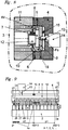
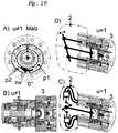
- Fig. 10 As can be seen, several types of power components 2 with a rotating inlet and outlet are conceivable, which can be combined with the controller 3 to form a turbo machine 1.
- the power part 2 consists of a GEROTOR machine with constant volume flow, as shown in FIG Fig.1 can be seen in the cut.
- a section through the GEROTOR machine is shown, which shows the two pressure areas with the drive pressures p1, p2.
- the reduction u is not equal to 1.
- the two pressure ranges with the drive pressures p1, p2 rotate with the speed nv.
- the advantage here is the simple and compact design of such a turbomachine 1.
- the power unit 2 consists of a GEROTOR machine which can be regulated in terms of volume flow. This is shown in section. The most important advantage here is the controllability of the volume flow, which is essential in many applications.
- the power part 2 consists of an axial piston machine with a swash plate.
- the shaft of this machine is directly connected to the distributor part 10 of the control 3.
- the reduction u is thus equal to 1.
- the power part 2 consists of a radial piston machine with connecting rods and a crankshaft.
- the shaft of this machine is directly connected to the distributor part 10 of the control 3.
- the reduction u is therefore equal to 1.
- a very central advantage of the turbo machine 1 according to the invention is to combine it with a large number of conceivable power components 2 in order to create an ideal solution for the respective application of the turbo machine 1.
Landscapes
- Engineering & Computer Science (AREA)
- Mechanical Engineering (AREA)
- General Engineering & Computer Science (AREA)
- Chemical & Material Sciences (AREA)
- Combustion & Propulsion (AREA)
- Control Of Turbines (AREA)
- Fluid Mechanics (AREA)
- Physics & Mathematics (AREA)
- Structures Of Non-Positive Displacement Pumps (AREA)
- Control Of Positive-Displacement Air Blowers (AREA)
- Hydraulic Motors (AREA)
- Fluid-Pressure Circuits (AREA)
- Rotary Pumps (AREA)
Claims (8)
- La machine à flux (1) pouvant fonctionner à la fois comme moteur et comme pompe, avec un arbre (Mw) monté axialement de manière fixe, comprenant une partie motrice (2) avec au moins une entrée et une sortie, un système de commande (3) qui comprend au moins une partie de raccordement (4) sur laquelle se trouve au moins une partie de distribution (10) avec des ouvertures de passage (26, 27) et au moins une partie d'alimentation (11) sont disposées, la partie de distribution (10) étant entraînée au moyen d'au moins un entraînement (12) disposé sur l'arbre (Mw) et les forces axiales étant réparties sur un piston (9) disposé axialement sur la partie de distribution (10), dans laquelle l'entrée et la sortie au moins prévues sur la partie motrice (2) sont conçues pour tourner et sont alimentées par la partie de distribution (10) et le piston (9) via la partie d'alimentation (11) avec au moins deux pressions d'entraînement en co-rotation (p1, p2), les pressions de commande (p1, p2) avec leurs surfaces annulaires (A1, A2) associées en saillie sur le piston (9) générant les forces Fp1 et Fp2, au moins une face frontale de la pièce de distribution (10) étant disposée sur au moins une surface de remplacement (B3, C3, C4,...) est soumise à au moins une autre pression (pw1, pw2,...),
caractérisé en ce que,
au moins une des autres zones de pression ou surfaces de remplacement (8, B3, C3, C4,...) est assurée par des conduites d'alimentation (24) et un dispositif de commande (13).) est relié par des conduites d'alimentation (24) et un dispositif de commande (13) à un entraînement (14) et est ainsi sollicité par une pression de commande (ps) et la force totale sur la face frontale (Fgsx) et le rendement (η) est ainsi modifié dans une plage de commande (19) par la force totale résultante (Fgx), qui presse les surfaces de contact entre le piston (9) et la partie distributeur (10), et entre la partie distributeur (10) et la partie conduite d'alimentation (11), l'une contre l'autre. - La machine à flux (1) selon la revendication 1,
caractérisé en ce que,
au moins une autre pression (pw1, pw2, ...), qui agit dans l'une des autres zones de pression ou sur les surfaces de remplacement (8, B3, C3, CA, ...), est reliée par des conduites d'alimentation (24) à une zone de fuite intérieure (7) et est donc égale à la pression de fuite intérieure (pli). - La machine à flux (1) selon la revendication 1 ou 2,
caractérisé en ce que,
la force de commande (Fs) est générée et agit sur le piston (9) via un dispositif de commande (13) et un entraînement du dispositif de commande (14), modifiant ainsi la force résultante globale (Fgx), une adaptation du rendement, un freinage, un blocage, un démarrage progressif ou une roue libre avec un courant de court-circuit interne et/ou externe (Vka, Vki) de la turbomachine (1) étant obtenue. - La machine à flux (1) selon l'une des revendications précédentes,
caractérisé en ce que,
la ligne d'alimentation des deux pressions de l'actionneur (p1, p2)a) en direction axiale presque droite oub) en direction radiale depuis l'intérieur ouc) en direction radiale depuis l'extérieur. - La machine à flux (1) selon l'une des revendications précédentes 2 à 4,
caractérisé en ce que,
la zone de fuite intérieure (7) est évacuée vers l'extérieur via un raccord de fuite (18) dans la pièce de raccordement (4) et/ou est reliée à un raccord respectif (5, 6) via un clapet antiretour respectif (1, 2, 16, 17). - La machine à flux (1) selon l'une des revendications précédentes 3 à 5,
caractérisé en ce que,
le piston (9) et/ou la pièce de distribution (10) et/ou la pièce d'alimentation (11) et/ou le dispositif de commande (13) est de conception magnétique. - La machine à flux (1) selon l'une des revendications précédentes 3 à 6,
caractérisé en ce que,
l'appareil de contrôle (14) est un électro-aimant. - La machine à flux (1) selon l'une des revendications précédentes,
caractérisé en ce que,
il existe un angle de réglage ξ entre la section de puissance 2 et la section de distribution 10, avec lequel la symétrie des courbes caractéristiques KO, K1, K2, K3 est modifiée.
Priority Applications (1)
| Application Number | Priority Date | Filing Date | Title |
|---|---|---|---|
| PL14809757T PL3055573T3 (pl) | 2013-10-08 | 2014-10-08 | Maszyna przepływowa, która może być użytkowana zarówno jako silnik hydrauliczny, jak i jako pompa |
Applications Claiming Priority (2)
| Application Number | Priority Date | Filing Date | Title |
|---|---|---|---|
| DE102013111098.3A DE102013111098B3 (de) | 2013-10-08 | 2013-10-08 | Strömungsmaschine |
| PCT/DE2014/100352 WO2015051784A2 (fr) | 2013-10-08 | 2014-10-08 | Turbomachine |
Publications (2)
| Publication Number | Publication Date |
|---|---|
| EP3055573A2 EP3055573A2 (fr) | 2016-08-17 |
| EP3055573B1 true EP3055573B1 (fr) | 2021-01-27 |
Family
ID=51787787
Family Applications (1)
| Application Number | Title | Priority Date | Filing Date |
|---|---|---|---|
| EP14809757.9A Active EP3055573B1 (fr) | 2013-10-08 | 2014-10-08 | Machine fluidique pouvant être opérée comme moteur hydraulique ou comme pompe |
Country Status (8)
| Country | Link |
|---|---|
| US (1) | US11174859B2 (fr) |
| EP (1) | EP3055573B1 (fr) |
| CN (1) | CN105814313B (fr) |
| DE (1) | DE102013111098B3 (fr) |
| DK (1) | DK3055573T3 (fr) |
| ES (1) | ES2862130T3 (fr) |
| PL (1) | PL3055573T3 (fr) |
| WO (1) | WO2015051784A2 (fr) |
Families Citing this family (1)
| Publication number | Priority date | Publication date | Assignee | Title |
|---|---|---|---|---|
| CN107762718B (zh) * | 2016-08-16 | 2020-03-17 | 博罗承创精密工业有限公司 | 一种气动马达 |
Family Cites Families (12)
| Publication number | Priority date | Publication date | Assignee | Title |
|---|---|---|---|---|
| US3572983A (en) * | 1969-11-07 | 1971-03-30 | Germane Corp | Fluid-operated motor |
| US3853435A (en) * | 1972-11-03 | 1974-12-10 | Kayaba Industry Co Ltd | Gerotor device with gear drive for commutator valve |
| US3799201A (en) * | 1973-04-05 | 1974-03-26 | Danfoss As | Distributor valve for an internally shafted orbital piston machine |
| DE3015551C2 (de) * | 1980-04-23 | 1986-10-23 | Mannesmann Rexroth GmbH, 8770 Lohr | Kreiskolbenmaschine |
| DE3029997C2 (de) * | 1980-08-08 | 1984-10-31 | Danfoss A/S, Nordborg | Hydraulischer, innenachsiger Kreiskolbenmotor |
| DE3424883A1 (de) * | 1984-07-06 | 1986-02-06 | Robert Bosch Gmbh, 7000 Stuttgart | Kraftstoffeinspritzpumpe fuer brennkraftmaschinen |
| US4992034A (en) * | 1989-04-24 | 1991-02-12 | Eaton Corporation | Low-speed, high-torque gerotor motor and improved valving therefor |
| DE19520405C2 (de) * | 1995-06-08 | 1998-09-24 | Danfoss As | Hydraulischer Kreiskolbenmotor |
| EP1074740B1 (fr) * | 1999-08-03 | 2001-12-19 | Siegfried A. Dipl.-Ing. Eisenmann | Machine hydrostatique à piston rotatif |
| CH701073B1 (de) | 2004-07-22 | 2010-11-30 | Siegfried A Dipl-Ing Eisenmann | Hydrostatischer Kreiskolbenmotor. |
| DE102005014654B4 (de) * | 2005-03-31 | 2014-03-06 | Gkn Driveline International Gmbh | Kraftfahrzeug-Hydraulikpumpe |
| DE102008025054B4 (de) * | 2008-05-26 | 2011-04-28 | Böhner-EH GmbH | Hydraulikeinheit |
-
2013
- 2013-10-08 DE DE102013111098.3A patent/DE102013111098B3/de not_active Expired - Fee Related
-
2014
- 2014-10-08 EP EP14809757.9A patent/EP3055573B1/fr active Active
- 2014-10-08 ES ES14809757T patent/ES2862130T3/es active Active
- 2014-10-08 PL PL14809757T patent/PL3055573T3/pl unknown
- 2014-10-08 CN CN201480061413.9A patent/CN105814313B/zh active Active
- 2014-10-08 WO PCT/DE2014/100352 patent/WO2015051784A2/fr not_active Ceased
- 2014-10-08 DK DK14809757.9T patent/DK3055573T3/da active
- 2014-10-08 US US15/028,192 patent/US11174859B2/en active Active
Non-Patent Citations (1)
| Title |
|---|
| None * |
Also Published As
| Publication number | Publication date |
|---|---|
| US20160252083A1 (en) | 2016-09-01 |
| PL3055573T3 (pl) | 2021-08-16 |
| WO2015051784A2 (fr) | 2015-04-16 |
| EP3055573A2 (fr) | 2016-08-17 |
| CN105814313A (zh) | 2016-07-27 |
| WO2015051784A3 (fr) | 2015-06-04 |
| DE102013111098B3 (de) | 2014-11-13 |
| US11174859B2 (en) | 2021-11-16 |
| ES2862130T3 (es) | 2021-10-07 |
| CN105814313B (zh) | 2018-08-31 |
| DK3055573T3 (da) | 2021-04-12 |
Similar Documents
| Publication | Publication Date | Title |
|---|---|---|
| DE2146026C2 (de) | Wellendichtungsanordnung | |
| EP3046815B1 (fr) | Unité de refoulement à débit volumique et régulation de pression, à commande électrique | |
| DE112015001050B4 (de) | Drehaktuator mit integrierter Betätigung | |
| EP2693054B1 (fr) | Dispositif de commande pour entraînements hydrostatiques | |
| EP3601805A1 (fr) | Dispositif de régulation d'une machine hydraulique | |
| WO2015062565A1 (fr) | Pompe à réfrigérant réglable | |
| EP2818726B1 (fr) | Pompe centrifuge avec roue à aubes déplaçable axialement pour l'alimentation de circuits différents | |
| DE102013008047A1 (de) | Drehzahlvariabler Antrieb mit zwei Pumpen und einem Differenzialzylinder | |
| EP2954214B1 (fr) | Turbomachine et élément de guidage d'écoulement pour une turbomachine | |
| EP2406508A1 (fr) | Palier lisse radial doté sélectivement d'une fonction hydrostatique et/ou hydrodynamique | |
| DE102016218186A1 (de) | Flügelzellenpumpe, Pumpensystem, Automatikgetriebe und Kraftfahrzeug | |
| AT413049B (de) | Dichtung zwischen zwei relativ zueinander bewegbaren teilen einer hydraulischen maschine | |
| EP3055573B1 (fr) | Machine fluidique pouvant être opérée comme moteur hydraulique ou comme pompe | |
| DE102015213338B4 (de) | Aktuatoreinheit | |
| EP2084395B1 (fr) | Ensemble de joint d'étanchéité entre deux parties mobiles l'une par rapport à l'autre d'une turbomachine | |
| WO2025119993A1 (fr) | Pompe à palettes à course unique réglable, procédé de fonctionnement d'une pompe, système de génération d'un flux de fluide sous pression, et système de direction | |
| WO2025119994A1 (fr) | Pompe à palettes à course unique réglable, procédé de fonctionnement de pompe à palettes et système de direction | |
| EP1378665A1 (fr) | Pompe à palettes | |
| DE102015016795A1 (de) | Druckwandler und Verfahren zur Druckwandlung | |
| EP3728851B1 (fr) | Pompe à palettes | |
| EP3091230B1 (fr) | Machine a piston hydrostatique | |
| DE2001614B2 (de) | Stromregeleinrichtung fur eine Hydraulikpumpe | |
| DE102012004303A1 (de) | Hydrostatischer Axialkolbenmotor | |
| DE102011109268A1 (de) | Hydraulik-Kleinaggregat geringer Förderleistung | |
| EP1318305A2 (fr) | Pompe à palettes |
Legal Events
| Date | Code | Title | Description |
|---|---|---|---|
| PUAI | Public reference made under article 153(3) epc to a published international application that has entered the european phase |
Free format text: ORIGINAL CODE: 0009012 |
|
| 17P | Request for examination filed |
Effective date: 20160503 |
|
| AK | Designated contracting states |
Kind code of ref document: A2 Designated state(s): AL AT BE BG CH CY CZ DE DK EE ES FI FR GB GR HR HU IE IS IT LI LT LU LV MC MK MT NL NO PL PT RO RS SE SI SK SM TR |
|
| AX | Request for extension of the european patent |
Extension state: BA ME |
|
| DAX | Request for extension of the european patent (deleted) | ||
| STAA | Information on the status of an ep patent application or granted ep patent |
Free format text: STATUS: REQUEST FOR EXAMINATION WAS MADE |
|
| STAA | Information on the status of an ep patent application or granted ep patent |
Free format text: STATUS: EXAMINATION IS IN PROGRESS |
|
| 17Q | First examination report despatched |
Effective date: 20200109 |
|
| GRAP | Despatch of communication of intention to grant a patent |
Free format text: ORIGINAL CODE: EPIDOSNIGR1 |
|
| STAA | Information on the status of an ep patent application or granted ep patent |
Free format text: STATUS: GRANT OF PATENT IS INTENDED |
|
| INTG | Intention to grant announced |
Effective date: 20200915 |
|
| GRAS | Grant fee paid |
Free format text: ORIGINAL CODE: EPIDOSNIGR3 |
|
| GRAA | (expected) grant |
Free format text: ORIGINAL CODE: 0009210 |
|
| STAA | Information on the status of an ep patent application or granted ep patent |
Free format text: STATUS: THE PATENT HAS BEEN GRANTED |
|
| AK | Designated contracting states |
Kind code of ref document: B1 Designated state(s): AL AT BE BG CH CY CZ DE DK EE ES FI FR GB GR HR HU IE IS IT LI LT LU LV MC MK MT NL NO PL PT RO RS SE SI SK SM TR |
|
| REG | Reference to a national code |
Ref country code: GB Ref legal event code: FG4D Free format text: NOT ENGLISH |
|
| REG | Reference to a national code |
Ref country code: CH Ref legal event code: EP |
|
| REG | Reference to a national code |
Ref country code: AT Ref legal event code: REF Ref document number: 1358586 Country of ref document: AT Kind code of ref document: T Effective date: 20210215 |
|
| REG | Reference to a national code |
Ref country code: IE Ref legal event code: FG4D Free format text: LANGUAGE OF EP DOCUMENT: GERMAN |
|
| REG | Reference to a national code |
Ref country code: DE Ref legal event code: R096 Ref document number: 502014015246 Country of ref document: DE |
|
| REG | Reference to a national code |
Ref country code: CH Ref legal event code: NV Representative=s name: DENNEMEYER AG, CH |
|
| REG | Reference to a national code |
Ref country code: DK Ref legal event code: T3 Effective date: 20210408 |
|
| REG | Reference to a national code |
Ref country code: SE Ref legal event code: TRGR |
|
| REG | Reference to a national code |
Ref country code: NL Ref legal event code: MP Effective date: 20210127 |
|
| REG | Reference to a national code |
Ref country code: LT Ref legal event code: MG9D |
|
| PG25 | Lapsed in a contracting state [announced via postgrant information from national office to epo] |
Ref country code: HR Free format text: LAPSE BECAUSE OF FAILURE TO SUBMIT A TRANSLATION OF THE DESCRIPTION OR TO PAY THE FEE WITHIN THE PRESCRIBED TIME-LIMIT Effective date: 20210127 Ref country code: GR Free format text: LAPSE BECAUSE OF FAILURE TO SUBMIT A TRANSLATION OF THE DESCRIPTION OR TO PAY THE FEE WITHIN THE PRESCRIBED TIME-LIMIT Effective date: 20210428 Ref country code: FI Free format text: LAPSE BECAUSE OF FAILURE TO SUBMIT A TRANSLATION OF THE DESCRIPTION OR TO PAY THE FEE WITHIN THE PRESCRIBED TIME-LIMIT Effective date: 20210127 Ref country code: LT Free format text: LAPSE BECAUSE OF FAILURE TO SUBMIT A TRANSLATION OF THE DESCRIPTION OR TO PAY THE FEE WITHIN THE PRESCRIBED TIME-LIMIT Effective date: 20210127 Ref country code: PT Free format text: LAPSE BECAUSE OF FAILURE TO SUBMIT A TRANSLATION OF THE DESCRIPTION OR TO PAY THE FEE WITHIN THE PRESCRIBED TIME-LIMIT Effective date: 20210527 Ref country code: BG Free format text: LAPSE BECAUSE OF FAILURE TO SUBMIT A TRANSLATION OF THE DESCRIPTION OR TO PAY THE FEE WITHIN THE PRESCRIBED TIME-LIMIT Effective date: 20210427 Ref country code: NL Free format text: LAPSE BECAUSE OF FAILURE TO SUBMIT A TRANSLATION OF THE DESCRIPTION OR TO PAY THE FEE WITHIN THE PRESCRIBED TIME-LIMIT Effective date: 20210127 Ref country code: NO Free format text: LAPSE BECAUSE OF FAILURE TO SUBMIT A TRANSLATION OF THE DESCRIPTION OR TO PAY THE FEE WITHIN THE PRESCRIBED TIME-LIMIT Effective date: 20210427 |
|
| PG25 | Lapsed in a contracting state [announced via postgrant information from national office to epo] |
Ref country code: RS Free format text: LAPSE BECAUSE OF FAILURE TO SUBMIT A TRANSLATION OF THE DESCRIPTION OR TO PAY THE FEE WITHIN THE PRESCRIBED TIME-LIMIT Effective date: 20210127 Ref country code: LV Free format text: LAPSE BECAUSE OF FAILURE TO SUBMIT A TRANSLATION OF THE DESCRIPTION OR TO PAY THE FEE WITHIN THE PRESCRIBED TIME-LIMIT Effective date: 20210127 |
|
| PG25 | Lapsed in a contracting state [announced via postgrant information from national office to epo] |
Ref country code: IS Free format text: LAPSE BECAUSE OF FAILURE TO SUBMIT A TRANSLATION OF THE DESCRIPTION OR TO PAY THE FEE WITHIN THE PRESCRIBED TIME-LIMIT Effective date: 20210527 |
|
| REG | Reference to a national code |
Ref country code: ES Ref legal event code: FG2A Ref document number: 2862130 Country of ref document: ES Kind code of ref document: T3 Effective date: 20211007 |
|
| REG | Reference to a national code |
Ref country code: DE Ref legal event code: R097 Ref document number: 502014015246 Country of ref document: DE |
|
| PG25 | Lapsed in a contracting state [announced via postgrant information from national office to epo] |
Ref country code: SM Free format text: LAPSE BECAUSE OF FAILURE TO SUBMIT A TRANSLATION OF THE DESCRIPTION OR TO PAY THE FEE WITHIN THE PRESCRIBED TIME-LIMIT Effective date: 20210127 Ref country code: CZ Free format text: LAPSE BECAUSE OF FAILURE TO SUBMIT A TRANSLATION OF THE DESCRIPTION OR TO PAY THE FEE WITHIN THE PRESCRIBED TIME-LIMIT Effective date: 20210127 Ref country code: EE Free format text: LAPSE BECAUSE OF FAILURE TO SUBMIT A TRANSLATION OF THE DESCRIPTION OR TO PAY THE FEE WITHIN THE PRESCRIBED TIME-LIMIT Effective date: 20210127 |
|
| PG25 | Lapsed in a contracting state [announced via postgrant information from national office to epo] |
Ref country code: SK Free format text: LAPSE BECAUSE OF FAILURE TO SUBMIT A TRANSLATION OF THE DESCRIPTION OR TO PAY THE FEE WITHIN THE PRESCRIBED TIME-LIMIT Effective date: 20210127 Ref country code: RO Free format text: LAPSE BECAUSE OF FAILURE TO SUBMIT A TRANSLATION OF THE DESCRIPTION OR TO PAY THE FEE WITHIN THE PRESCRIBED TIME-LIMIT Effective date: 20210127 |
|
| PLBE | No opposition filed within time limit |
Free format text: ORIGINAL CODE: 0009261 |
|
| STAA | Information on the status of an ep patent application or granted ep patent |
Free format text: STATUS: NO OPPOSITION FILED WITHIN TIME LIMIT |
|
| 26N | No opposition filed |
Effective date: 20211028 |
|
| PG25 | Lapsed in a contracting state [announced via postgrant information from national office to epo] |
Ref country code: AL Free format text: LAPSE BECAUSE OF FAILURE TO SUBMIT A TRANSLATION OF THE DESCRIPTION OR TO PAY THE FEE WITHIN THE PRESCRIBED TIME-LIMIT Effective date: 20210127 |
|
| PG25 | Lapsed in a contracting state [announced via postgrant information from national office to epo] |
Ref country code: SI Free format text: LAPSE BECAUSE OF FAILURE TO SUBMIT A TRANSLATION OF THE DESCRIPTION OR TO PAY THE FEE WITHIN THE PRESCRIBED TIME-LIMIT Effective date: 20210127 |
|
| PG25 | Lapsed in a contracting state [announced via postgrant information from national office to epo] |
Ref country code: IS Free format text: LAPSE BECAUSE OF FAILURE TO SUBMIT A TRANSLATION OF THE DESCRIPTION OR TO PAY THE FEE WITHIN THE PRESCRIBED TIME-LIMIT Effective date: 20210527 |
|
| REG | Reference to a national code |
Ref country code: BE Ref legal event code: MM Effective date: 20211031 |
|
| PG25 | Lapsed in a contracting state [announced via postgrant information from national office to epo] |
Ref country code: MC Free format text: LAPSE BECAUSE OF FAILURE TO SUBMIT A TRANSLATION OF THE DESCRIPTION OR TO PAY THE FEE WITHIN THE PRESCRIBED TIME-LIMIT Effective date: 20210127 |
|
| PG25 | Lapsed in a contracting state [announced via postgrant information from national office to epo] |
Ref country code: LU Free format text: LAPSE BECAUSE OF NON-PAYMENT OF DUE FEES Effective date: 20211008 Ref country code: BE Free format text: LAPSE BECAUSE OF NON-PAYMENT OF DUE FEES Effective date: 20211031 |
|
| PG25 | Lapsed in a contracting state [announced via postgrant information from national office to epo] |
Ref country code: HU Free format text: LAPSE BECAUSE OF FAILURE TO SUBMIT A TRANSLATION OF THE DESCRIPTION OR TO PAY THE FEE WITHIN THE PRESCRIBED TIME-LIMIT; INVALID AB INITIO Effective date: 20141008 |
|
| PG25 | Lapsed in a contracting state [announced via postgrant information from national office to epo] |
Ref country code: CY Free format text: LAPSE BECAUSE OF FAILURE TO SUBMIT A TRANSLATION OF THE DESCRIPTION OR TO PAY THE FEE WITHIN THE PRESCRIBED TIME-LIMIT Effective date: 20210127 |
|
| PG25 | Lapsed in a contracting state [announced via postgrant information from national office to epo] |
Ref country code: MK Free format text: LAPSE BECAUSE OF FAILURE TO SUBMIT A TRANSLATION OF THE DESCRIPTION OR TO PAY THE FEE WITHIN THE PRESCRIBED TIME-LIMIT Effective date: 20210127 |
|
| PG25 | Lapsed in a contracting state [announced via postgrant information from national office to epo] |
Ref country code: MT Free format text: LAPSE BECAUSE OF FAILURE TO SUBMIT A TRANSLATION OF THE DESCRIPTION OR TO PAY THE FEE WITHIN THE PRESCRIBED TIME-LIMIT Effective date: 20210127 |
|
| REG | Reference to a national code |
Ref country code: CH Ref legal event code: U11 Free format text: ST27 STATUS EVENT CODE: U-0-0-U10-U11 (AS PROVIDED BY THE NATIONAL OFFICE) Effective date: 20251101 |
|
| PGFP | Annual fee paid to national office [announced via postgrant information from national office to epo] |
Ref country code: DE Payment date: 20251212 Year of fee payment: 12 |
|
| PGFP | Annual fee paid to national office [announced via postgrant information from national office to epo] |
Ref country code: GB Payment date: 20251022 Year of fee payment: 12 |
|
| PGFP | Annual fee paid to national office [announced via postgrant information from national office to epo] |
Ref country code: AT Payment date: 20251022 Year of fee payment: 12 |
|
| PGFP | Annual fee paid to national office [announced via postgrant information from national office to epo] |
Ref country code: DK Payment date: 20251027 Year of fee payment: 12 Ref country code: IT Payment date: 20251024 Year of fee payment: 12 |
|
| PGFP | Annual fee paid to national office [announced via postgrant information from national office to epo] |
Ref country code: FR Payment date: 20251030 Year of fee payment: 12 |
|
| PGFP | Annual fee paid to national office [announced via postgrant information from national office to epo] |
Ref country code: TR Payment date: 20251006 Year of fee payment: 12 |
|
| PGFP | Annual fee paid to national office [announced via postgrant information from national office to epo] |
Ref country code: SE Payment date: 20251021 Year of fee payment: 12 Ref country code: CH Payment date: 20251101 Year of fee payment: 12 |
|
| PGFP | Annual fee paid to national office [announced via postgrant information from national office to epo] |
Ref country code: IE Payment date: 20251024 Year of fee payment: 12 |
|
| PGFP | Annual fee paid to national office [announced via postgrant information from national office to epo] |
Ref country code: PL Payment date: 20251003 Year of fee payment: 12 |
|
| PGFP | Annual fee paid to national office [announced via postgrant information from national office to epo] |
Ref country code: ES Payment date: 20251210 Year of fee payment: 12 |