EP3055681B1 - Verfahren und vorrichtung zur inspektion von verpackungsnähten - Google Patents
Verfahren und vorrichtung zur inspektion von verpackungsnähten Download PDFInfo
- Publication number
- EP3055681B1 EP3055681B1 EP14790237.3A EP14790237A EP3055681B1 EP 3055681 B1 EP3055681 B1 EP 3055681B1 EP 14790237 A EP14790237 A EP 14790237A EP 3055681 B1 EP3055681 B1 EP 3055681B1
- Authority
- EP
- European Patent Office
- Prior art keywords
- light
- camera
- package
- image
- weld
- Prior art date
- Legal status (The legal status is an assumption and is not a legal conclusion. Google has not performed a legal analysis and makes no representation as to the accuracy of the status listed.)
- Active
Links
Images



Classifications
-
- G—PHYSICS
- G01—MEASURING; TESTING
- G01N—INVESTIGATING OR ANALYSING MATERIALS BY DETERMINING THEIR CHEMICAL OR PHYSICAL PROPERTIES
- G01N21/00—Investigating or analysing materials by the use of optical means, i.e. using sub-millimetre waves, infrared, visible or ultraviolet light
- G01N21/84—Systems specially adapted for particular applications
- G01N21/88—Investigating the presence of flaws or contamination
- G01N21/90—Investigating the presence of flaws or contamination in a container or its contents
- G01N21/9054—Inspection of sealing surface and container finish
-
- G—PHYSICS
- G01—MEASURING; TESTING
- G01N—INVESTIGATING OR ANALYSING MATERIALS BY DETERMINING THEIR CHEMICAL OR PHYSICAL PROPERTIES
- G01N21/00—Investigating or analysing materials by the use of optical means, i.e. using sub-millimetre waves, infrared, visible or ultraviolet light
- G01N21/84—Systems specially adapted for particular applications
- G01N21/88—Investigating the presence of flaws or contamination
- G01N21/95—Investigating the presence of flaws or contamination characterised by the material or shape of the object to be examined
-
- G—PHYSICS
- G01—MEASURING; TESTING
- G01N—INVESTIGATING OR ANALYSING MATERIALS BY DETERMINING THEIR CHEMICAL OR PHYSICAL PROPERTIES
- G01N21/00—Investigating or analysing materials by the use of optical means, i.e. using sub-millimetre waves, infrared, visible or ultraviolet light
- G01N21/84—Systems specially adapted for particular applications
- G01N21/88—Investigating the presence of flaws or contamination
- G01N21/8851—Scan or image signal processing specially adapted therefor, e.g. for scan signal adjustment, for detecting different kinds of defects, for compensating for structures, markings, edges
-
- G—PHYSICS
- G01—MEASURING; TESTING
- G01N—INVESTIGATING OR ANALYSING MATERIALS BY DETERMINING THEIR CHEMICAL OR PHYSICAL PROPERTIES
- G01N21/00—Investigating or analysing materials by the use of optical means, i.e. using sub-millimetre waves, infrared, visible or ultraviolet light
- G01N21/84—Systems specially adapted for particular applications
- G01N21/88—Investigating the presence of flaws or contamination
- G01N21/8851—Scan or image signal processing specially adapted therefor, e.g. for scan signal adjustment, for detecting different kinds of defects, for compensating for structures, markings, edges
- G01N2021/8887—Scan or image signal processing specially adapted therefor, e.g. for scan signal adjustment, for detecting different kinds of defects, for compensating for structures, markings, edges based on image processing techniques
-
- G—PHYSICS
- G01—MEASURING; TESTING
- G01N—INVESTIGATING OR ANALYSING MATERIALS BY DETERMINING THEIR CHEMICAL OR PHYSICAL PROPERTIES
- G01N2201/00—Features of devices classified in G01N21/00
- G01N2201/10—Scanning
- G01N2201/105—Purely optical scan
Definitions
- the present invention relates to the technical field of inspection of heat-sealed packaging in the general sense.
- the object of the invention finds applications that are particularly advantageous, but not exclusively, in the field of control of the packaging of products in the agri-food, pharmacy or cosmetic field.
- the invention also applies to other packaging such as pouches where two films are welded together.
- each heat-sealed package comprises at least one receptacle for receiving the product to be packaged.
- Each cell is closed by a film which is welded to the cell.
- the junction zone between the film and the cell corresponds to the weld surrounding the cell being located generally at the edge of the cell.
- the welds are in the form of a ribbon delimited by two opposite edges on either side of a guide curve.
- the document EP 2,350,621 discloses methods for detecting in the weld zone the presence of intruders which leads to an alteration on the one hand, of the quality of the weld from the point of view of sealing and, on the other hand, of the aesthetic appearance related to the product and packaging.
- This solution makes it possible to detect as a cause of non-welding only the presence of the contaminants, and does not make it possible to detect weld defects due to bubbles, unwelded regions or colorless fatty or wet parts.
- the proposed technique is insufficient to guarantee the quality of the welds.
- the patent application WO 2013/007951 discloses a method for controlling in particular the heat-sealed packaging structures using a linear image sensor. This method is to illuminate the packages with a light beam scanning the welds in a scanning direction extending transversely to the scanning direction.
- the method aims to acquire cyclically for each increment of motion, a sequence of n successive images each obtained with different exposure times and / or different lighting conditions.
- the method further aims to bring together the image lines obtained in the sequences with both the same exposure time and the same lighting conditions so as to obtain n superimposable images obtained with different exposure times and / or in different lighting conditions.
- the method aims to analyze separately or in combination the images to determine at least one characteristic of the inspected packages.
- This patent application describes a packaging inspection technique, simple and inexpensive to implement, while being designed to allow full control of an inspection area with locally inhomogeneous characteristics.
- this document does not provide information on the method for analyzing the images to detect whether the packages are correctly or non-welded.
- the inspection technique described by this document does not give the possibility of detecting whether the packages are correctly or not welded.
- the patent US 5,515,159 discloses a vision system for inspecting packaging welds. This document provides for illuminating the package using structured lighting to detect welds characterized by a footprint created by the striking effect during the sealing operation. This document also provides for using backscattered lighting to visualize welding defects.
- This system also includes a camera for obtaining an image of the package. The image is analyzed to determine the transverse width of the weld to determine the weld's compliance with a reference value.
- This patent discloses an inspection technique limited to welds having an impression due to the striking stroke during the heat sealing operation. Furthermore, the inspection technique described by this patent does not provide an image of the welds with sufficient precision to determine whether the packages are correctly or not welded.
- the present invention therefore aims to overcome the drawbacks of the prior art by proposing a technique for controlling the welds presented by heat-sealed packages, by detecting with great precision, the welded or non-welded parts, in order to highlight any parts Unwelded and accurately measure the width of the weld, and this all along the weld guideline so as to determine if the packages are defective or properly welded.
- Another object of the invention is to control the quality of the welds of the packages by an optical process operating through a transparent or translucent part and offering the advantage of controlling at a speed adapted to the manufacturing process and without direct contact with the packaging.
- the invention provides a method for inspecting package welds according to claim 1.
- Another object of the invention is to provide a device for inspecting packaging welds according to claim 11.
- the invention therefore consists in controlling the assembled zone consisting of the two welded films (cell and upper film) by analysis of the light diffusion properties in the welded zone, that is to say by analysis of the reflected or transmitted light. non-specularly by the package.
- the object of the invention is to determine the actual area of welding and to measure the width of the weld.
- the invention is based on the modification of the optical diffusion properties of the materials used for the manufacture of packaging that are modified after welding (heating of the material and welding of the two superposed films). This property modification will be used by the invention to determine the areas actually welded.
- the object of the invention relates to a device 1 for inspecting the welds 2 of heat-sealed packages 3 in order to determine the conformity or otherwise of the welds.
- the heat-sealed packs 3 each comprise a receptacle 4 for receiving a product and each cell 4 is closed by a film 5 which is fixed on the cell by a weld 2.
- the packaging 3 is suitable for packaging products in the agri-food field, but it is clear that the inspection device according to the invention can be applied to packaging in different technical fields.
- the weld 2 has a substantially rectangular geometric shape but it is clear that the invention is applicable for inspecting welds having different geometries.
- a weld 2 is considered as a ribbon or a strip delimited by two opposite edges d, e located on either side of a directing curve C along which the weld extends.
- the inspection device 1 also comprises at least one light source 9 illuminates the packages 3 by a light beam 10 extending in a control direction Y so as to cover a field of width L in which are located two welds to be inspected .
- the ideal beam 10 produced on the package 3 in a scanning direction X at least one and in the example shown in FIG. Fig . 2 , Two light t transitions extending across the field width L.
- the light beam 10 provides a light band producing two light t transitions extending across the field width L.
- the light beam 10 produces a narrow luminous line extending over the entire width of the field L and having in the scanning direction X a peak comprised between two close light transitions.
- a light transition t it must be understood a rapid change of light level, more precisely of the illumination produced in the X direction.
- the illumination function in the X direction tends to a step-type function.
- the light source 9 is anamorphic laser, or focused lighting based on LED technology.
- the inspection device 1 also comprises a camera 13 provided with a lens 14 having a rectangular field of size WxH, with L corresponding to the packing control width in the Y direction and a dimension extending in a H direction perpendicular to the control direction Y.
- the images acquired by the camera are transmitted to an image processing unit 15 which will be described in detail in the following description.
- the inspection device 1 also comprises a system 16 for scanning, according to the scanning direction X , the welds 2 by the light beam 10 and the rectangular field of the camera 13.
- a scanning system 16 makes it possible to illuminate the welds 2 (by the beam 10 ) and to take images (by the camera 13) of the illuminated seams 2 , and this for all the welds of the packages.
- the X scanning direction is perpendicular to the direction Y of control since the reference X, Y, Z is orthonormal.
- the scan direction X is generally transverse to the control direction Y, to allow the entire weld to be covered by the beam 10 and the field of the camera.
- the scanning system 16 of the welds 2 by the light beam 10 and the rectangular field LxH of the camera 13 is a means of displacement in continuous translation or by saccades, packaging in the field of the camera 13.
- the camera 13 is fixed and can be placed at the output of the packaging production line which are conventionally moved in translation by a conveyor.
- the cells are interconnected and no cutting of the film and cell strip has been done before control.
- the packages are thus brought to pass in front of a control station, either continuously on a conveyor line, or by saccade corresponding to the operation of the thermoformer.
- the system 16 for scanning the welds 2 by the light beam 10 and the rectangular field LxH of the camera 13 comprises means for moving optical devices relative to the fixed packaging or advancing by jerks.
- the system 16 for scanning the welds 2 by the light beam 10 and the rectangular field LxH of the camera 13 comprises optical devices for deflecting the light rays coming from the light source 9 and light rays captured. by the camera 13, said optical devices being interposed between the packages on the one hand and the light source 9 and the camera 13 on the other hand.
- the scanning system 16 delivers to the processing unit 15, positioning information of the packages 3 with respect to the field of the camera.
- the scanning system 16 performs N increments of scanning to inspect all the welds 2 of a package 3.
- each raw matrix image B (N) encompasses the light transition (s) t.
- the Fig. 3 An example of a matrix raw image B (N) of a portion of a package having a solder 2.
- This matrix raw image B (N) contains the two light transitions t provided by a light ray and has a rectangular field of dimensions LxH, with L corresponding to the packing control width in the Y direction and a dimension H extending in the scanning direction X which is transverse to the control direction Y.
- the raw matrix images B (N) delivered successively by the camera 13 during the N increments are acquired and processed by the processing unit 15 .
- the processing unit 15 comprises means for implementing the method according to the invention which will be described more precisely in the following description. This processing unit 15 also comprises data storage means as will appear in the following description.
- the method consists for each image B (N) acquired, to extract over the entire width of the field L, a measurement of the diffusion by the packaging of the light transition t, or as in the illustrated example , two light transitions t. These measurements of the diffusion by the packaging of the light transitions t are recorded.
- the method according to the invention thus exploits the differences in light diffusion property in the packaging, specific to the welded zones or welds 2 on the one hand and the non-welded zones on the other hand.
- the material of a non-welded part diffuses little light and it does not propagate in the thickness of the material at the interface of the film and the cell.
- the material of a welded part is conversely more diffusing and in particular the light propagates then diffuses in the heart of this welded part.
- FIG. 3 On the Fig. 3 , there appears a zone Z 1 of light scattering corresponding to a part of the unwelded packaging and a zone Z 2 of greater light scattering corresponding to a welded portion of the package.
- the Fig. 3A gives an example of a curve giving from the matrix raw image illustrated in the Fig . 3 , gray level curves extending in the scanning direction X.
- the gray level curve A of the pixels of the camera taken at a point A 1 according to the field width L is located in the zone Z 1 while the curve of the gray level B taken at a point B 1 different from the point A 1 is located in zone Z 2 .
- the light scattering zones ie zone Z 2 in the example illustrated in FIG. Fig. 3
- the welded zones so that by analyzing these zones, the welded zones can be measured.
- inverse diffusion properties that is to say that the material of a welded portion is low scattering.
- the measurement of the diffusion by the package of the light transition (s) t in the matrix raw image B (N) is the spread of the light transition (s) t.
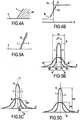
- This spreading can be characterized in different ways, as for example by the decrease of light gradient in the vicinity of the transition ( Fig. 4A, 4B ), by moving a point (PA to PB ) crossing a defined light threshold ( Fig . 5A, 5B ), or by measuring the gray level of the pixels considered along selected lines outside the illuminated area, but in the vicinity of the light transition ( Fig . 5C ), or by measuring the gray level at the peak of the gray values ( Fig. 5D ).
- the light beam 10 is a light band producing a light transition t in the field LxH of the camera.
- the diffusion measurement is obtained by analyzing this light transition t of this light band.
- the Fig. 4B shows the gray level of the pixels of the camera according to the scanning direction X, for the light transition t having little diffusion (curve A ) and having diffusion (curve B ).
- the curve A with little diffusion has, at the transition, a slope TA while the curve B having diffusion has a slope TB of value less than the slope TA.
- the diffusion measurement can thus be characterized by the gradient of light in the vicinity of the transition, that is to say by the slope of the gray levels. The lower the slope, the greater the diffusion.
- the light beam 10 is a narrow luminous ray producing two light transitions t in the field LxH of the camera ( Fig. 5A ).
- a narrow luminous line is understood to mean a luminous ray whose width is such that an attenuation of the peak of gray level appears when the light is diffused at inside the material. The diffusion measurement is obtained by analyzing this light line or at least one transition t.
- the Fig. 5B shows the gray level in the X scanning direction , for light transitions t with little diffusion (curve A ) and having diffusion (curve B).
- a light threshold value S the curve with little diffusion A present at the point crossing the threshold S, two transition points PA and QA remote therebetween a width IA while curve B with diffusion present at the crossing point of the threshold S, two transition points PB and QB distant from each other by a width IB which is greater than the width IA .
- the width IA or IB measures the diffusion. The greater the width, the greater the diffusion. It should be noted that in the illustrated example, the width is taken on the light areas Zt of the two light transitions t .
- the scattering measurement is obtained by measuring the gray level along a selected line J taken at a given location of the scanning direction X.
- the gray level NA for a curve A with little diffusion is less at gray level NB of a curve B having an important diffusion character.
- grayscale NA, NB characterize the diffusion of the transition t.
- the gray level NA, NB measures the diffusion. The higher the gray level, the greater the diffusion.
- the diffusion measurement is obtained by measuring the gray level at the peak of the gray values.
- the gray level of the peak HA of a curve A with little diffusion is greater than the gray level HB of the peak of a curve B exhibiting an important diffusion character.
- the gray level of the peak may advantageously be taken as the maximum value of gray level considered during a search in the X- scan direction .
- the decrease in the height of the peak of the level characterizes the diffusion. The lower the height of the peak, the greater the diffusion.
- the ratio of peak heights or difference in peak heights is also a feature of diffusion.
- the method according to the invention thus consists of extracting and memorizing, for each matrix raw image B (N); and over the entire width L of the field, measurements of the scattering by the packaging, or bright transitions obtained according to either of the methods described above.
- N matrix raw image
- L width of the field
- measurements of the scattering by the packaging or bright transitions obtained according to either of the methods described above.
- a diffusion function which according to the principles described above, can be expressed in the following way: I (y), N (y), HA -HB (y) or P (y).
- the method according to the invention then consists, for each of the N successive scanning increments, of creating from the matrix raw image B (N), an image line I (N) of width L , each pixel of which receives value, the measurement in the matrix raw image B (N) of the diffusion of the light transitions.
- the Fig. 6 is an example of an image line I (N) obtained from the diffusion values extracted from the matrix raw image B (N) shown in FIG. Fig. 3 .
- the method according to the invention then consists in recording, after each other, at least N lines of images I (N) in order to obtain, by juxtaposition, a matrix image I containing at least the two opposite edges of each other.
- a matrix image I containing at least the two opposite edges of each other.
- e of the weld for at least a portion of the guide curve C Fig. 7A and 7B are examples of matrix images I containing a part of the package in which a portion of the solder 2 appears. It should be noted that in the example shown in Fig. 7A , Welding 2 appears dark, while in the example shown in Fig. 7B , the solder appears clear.
- the minimum thickness corresponds to the limit value below which it is considered that the width of the weld is not sufficient to ensure correct packaging. Thus, if the thickness of the weld 2 is in any point greater than this minimum value then the weld 2 of the packaging is considered correct. Conversely, if the thickness of the weld 2 is less than this minimum value then the weld 2 of the packaging is considered to be defective.
- transverse width a of the weld 2 means, according to a first variant, the width a 1 of the weld tape measured perpendicular to the guideline C at any point along the ribbon .
- pixel measurements are obtained by any method borrowed from image processing techniques such as related or unrelated pixel counts along segments orthogonal to the C-directional curve , or by contour detection and distance measurements between contours.
- the analysis of the image I begins as soon as one has obtained by scanning an image I containing at least the two opposite edges d, e of the weld for at least a portion of the guide curve. vs.
- the analysis of the image I is carried out only for a surface inspection area much smaller than the image I but including at least the weld 2 considered to be correct.
- This inspection zone is a region geometrically defined beforehand and positioned in the image I, either according to the prior knowledge of the position of the packages during the inspection, or according to the results of a step of locating the sold by image analysis I.
- the object of the invention is to control the quality of the welds by analyzing the scattering properties of the light reflected or transmitted by the package.
- the angle of incidence ⁇ of projection of the light beam 10 and of observation ⁇ of the camera defined as the angle between its optical axis and the normal to the surface of the packaging, are chosen so as not to acquire the reflected light or specularly transmitted by the package.
- the angle of incidence ⁇ of projection of the light beam and of observation ⁇ of the camera defined as the angle between its optical axis and the normal to the surface of the package, are chosen so as to limit and even remove the occultation of the weld by the edges of the cells of the packages.
- the Fig . 1 and 9 illustrate two variants of reflection mounting of the device according to the invention in which the camera 13 and the light source 9 are arranged on the same side of the package 3.
- the camera 13 and the light source 9 are arranged on the side of the cell 4 of the package 3.
- This arrangement is particularly suitable for a reduced thickness packaging having an opaque film that can be printed at the weld.
- the camera 13 and the light source 9 are arranged on the opposite side to the cell 4 of the package 3.
- This arrangement is particularly suitable for any thickness of packaging having a translucent film uniformly printed at the weld.
- the light beam 10 has a spectral composition able to pass through the material of the package.
- the light beam 10 has a spectral composition capable of being strongly absorbed by at least one specific type of intruder.
- the Fig , 11 and 12 illustrate an alternative embodiment of the invention making it possible to inspect the welds made more particularly on packages 3 whose relative geometry height tray / welding position does not make possible the observation of this weld under the observation angle ⁇ of 13.
- a masked area for the camera appears for the portion of the package located at the bottom of the front of the face 23 ( Fig . 1 ) while the part of the package located at the bottom of the back of face 24 ( Fig. 1 ) is visible.
- the device according to the invention comprises an optical system 18 interposed between the packages 3 and the camera 13 and two light sources 9, 9 1 .
- the optical system 18 is designed so that on the one hand the angles of incidence of projection of the light beams from the two light sources 9 , 9 1 and on the other hand the observation angles of the camera are symmetrical with respect to the normal to the package.
- the implementation of such an optical assembly makes it possible to observe the embayment 3 along two symmetrical observation axes making it possible to eliminate the masked areas.
- the Fig. 12 illustrates an exemplary embodiment of an exemplary mounting according to which the light sources 9 , 9 1 such as laser diodes are situated on either side of the camera 13.
- the optical system 18 comprises a first set of symmetrical mirrors 19 placed opposite the light sources 9, 9 1 and the camera 13 and positioned for returning the beams to a second set of symmetrical mirrors 20 positioned to illuminate and observe the packaging 3 symmetrically with respect to the normal packaging.
- a lens 22 is positioned in the path of each optical path of the beams, between the mirrors 20 of the second clearance and the package 3.
- each light beam extends transversely to the scanning direction X and produced on the package 3 in the scanning direction X at least one light transition t extending over the field width L.
- the light sources 9 , 9 1 are controlled in lighting-extinguishing by a control unit controlling either the simultaneous operation of the two sources, or the alternating operation of the two sources on the half-length of the package considered in the scanning direction.
- the camera 13 ensures the reconstruction of two images corresponding to the observation according to different optical paths of the package, according to at least its half-lengths.
- the camera 13 can reconstruct two complete images of the package observed under the two symmetrical observation angles.
- the image processing unit then exploits only the part of each image that is not masked.
- the camera reconstructs during each illumination, an image corresponding to half of the observed unmasked package.
- the processing unit 15 processes the images according to the method described above.
Landscapes
- Chemical & Material Sciences (AREA)
- General Physics & Mathematics (AREA)
- Pathology (AREA)
- Physics & Mathematics (AREA)
- Health & Medical Sciences (AREA)
- Life Sciences & Earth Sciences (AREA)
- Immunology (AREA)
- Biochemistry (AREA)
- Analytical Chemistry (AREA)
- General Health & Medical Sciences (AREA)
- Engineering & Computer Science (AREA)
- Computer Vision & Pattern Recognition (AREA)
- Signal Processing (AREA)
- Investigating Materials By The Use Of Optical Means Adapted For Particular Applications (AREA)
- Length Measuring Devices By Optical Means (AREA)
Claims (22)
- Verfahren zur Prüfung von Schweißnähten (2) von Verpackungen (3), wobei die Schweißnähte in Form eines Streifens, welcher durch zwei gegenüberliegende Ränder (d, e) auf beiden Seiten einer Leitkurve (C) begrenzt ist, vorliegen, darin bestehend:- die Schweißnähte (2) in einer Abtastrichtung (X) mittels eines Lichtstrahls (10), welcher durch eine die Verpackungen beleuchtende Lichtquelle (9) geliefert wird, abzutasten, wobei der Strahl sich in einer Richtung (Y) quer zu der Abtastrichtung (X) erstreckt, um eine Feldbreite (L) abzudecken,- bei jedem der aufeinanderfolgenden N Abtastschritte ein Matrixrohbild (B(N)) der beleuchteten Verpackungen mit Hilfe einer Kamera (13) aufzunehmen, die mit einem Objektiv ausgestattet ist und deren rechteckiges Feld die Abmessungen LxH aufweist, wobei H sich in der Abtastrichtung (X) erstreckt und L einer Prüfbreite (L) in der zu der Abtastrichtung (X) orthogonalen Richtung (Y) entspricht, und die durch die Kamera gelieferten Bilder zu analysieren,dadurch gekennzeichnet, dass:- ein Lichtstrahl (10) erstellt wird, der auf der Verpackung in der Abtastrichtung (X) wenigstens einen sich über die Feldbreite (L) erstreckenden Lichtübergang (t) erzeugt,- ein Matrixrohbild (B(N)), welches den Lichtübergang (t) einschließt, aufgenommen wird,- aus jedem erhaltenen Matrixrohbild (B(N)) über die gesamte Feldbreite (L) ein Maß der Diffusion des Lichtübergangs (t) durch die Verpackung extrahiert und gespeichert wird,- für einen jeden der aufeinanderfolgenden N Abtastschritte aus dem Matrixrohbild (B(N)) eine Bildzeile (I(N)) mit der Breite (L) erstellt wird, von der jedes Pixel das Maß der Diffusion wenigstens des Lichtübergangs (t) in dem Matrixrohbild (B(N)) als Wert erhält,- in der Folge wenigstens N Bildzeilen (I(N)) aufgezeichnet werden, um durch Aneinanderreihung ein Matrixbild (I) zu erhalten, das wenigstens die beiden gegenüberliegenden Ränder (d, e) der Schweißnaht für wenigstens einen Abschnitt der Leitkurve (C) enthält, und- das Matrixbild (I) analysiert wird:∘ indem die zu der Schweißnaht gehörenden Pixel dank ihres Wertes erkannt werden,∘ indem an jeder Stelle entlang des Abschnittes der Leitkurve (C) als Merkmal der Schweißnaht wenigstens die Querbreite (a) bestimmt wird,∘ indem die Korrektheit der Schweißnaht über den Abschnitt bestimmt wird, wenn ihre Querbreite (a) an jeder Stelle größer als ein gegebenes Minimum bleibt.
- Verfahren nach Anspruch 1, dadurch gekennzeichnet, dass bei einem Segmentierungsschritt:- die Pixel mit Diffusionswerten in einem bestimmten Intervall als potentiell zur Schweißnaht gehörend vorausgewählt werden,- in der Nähe der Leitkurve (C) aus den vorausgewählten Pixeln eine Menge von zusammenhängenden Pixeln ausgewählt wird, um zusammen die Schweißnaht zu bilden.
- Verfahren nach Anspruch 1, dadurch gekennzeichnet, dass es darin besteht, die Diffusion des Übergangs in dem Matrixrohbild (B(N)) unter Berücksichtigung der Ausbreitung des Übergangs zu messen, die entweder durch den Abfall des Lichtgradienten in der Nähe des Übergangs oder durch die Bewegung einer Stelle des Überschreitens einer definierten Lichtschwelle oder durch Messen des Grauwertes der betrachteten Pixel entlang von ausgewählten Linien, die außerhalb des beleuchteten Bereichs, aber in der Nähe des Lichtübergangs liegen, gekennzeichnet ist.
- Verfahren nach Anspruch 1 bis 3, dadurch gekennzeichnet, dass als Lichtstrahl ein Lichtband projiziert wird, das zwei Lichtübergänge in dem Feld (LxH) der Kamera erzeugt, und das Diffusionsmaß durch Analyse der beiden Übergänge erhalten wird.
- Verfahren nach den Ansprüchen 1 bis 3, dadurch gekennzeichnet, dass als Lichtstrahl ein schmaler Lichtstreifen projiziert wird, dessen Querschnitt einem Lichtpeak entspricht.
- Verfahren nach Anspruch 5, dadurch gekennzeichnet, dass das Diffusionsmaß durch Ausbreitung des Lichtpeaks erhalten wird, die entweder durch die Breite zwischen den beiden Stellen des Überschreitens einer definierten Lichtschwelle oder durch die Höhenabnahme des Peaks oder durch die Messung der Grauwerte der betrachteten Pixel entlang von ausgewählten Linien, die auf beiden Seiten des beleuchteten Bereichs, außerhalb, aber in der Nähe des Lichtübergangs liegen, oder durch den Abfall des Lichtgradienten in der Nähe des Übergangs bestimmt ist.
- Verfahren nach Anspruch 1, dadurch gekennzeichnet, dass es darin besteht, das Bild (I) lediglich für einen Prüfbereich mit weitaus kleinerer Fläche als das Bild (I), der jedoch wenigstens die als fehlerfrei betrachtete Schweißnaht einschließt, zu analysieren, wobei der Prüfbereich ein Bereich ist, der zuvor geometrisch definiert wird, und in dem Bild (I) gelegen ist, entweder in Abhängigkeit von der vorherigen Kenntnis der Position der Verpackungen während der Prüfung oder in Abhängigkeit von den Ergebnissen eines Schrittes zur Lokalisierung der Schweißnaht durch Analyse des Bildes (I).
- Verfahren nach Anspruch 1, dadurch gekennzeichnet, dass es darin besteht, das Bild (I) zu analysieren, sobald es durch Abtasten erhalten wird, wobei ein Bild (I) wenigstens die beiden gegenüberliegenden Ränder (d, e) der Schweißnaht für wenigstens einen Abschnitt der Leitkurve (C) enthält.
- Verfahren nach Anspruch 1, dadurch gekennzeichnet, dass es darin besteht, den Einfallwinkel (α) der Projektion des Lichtstrahls (10) und Betrachtungswinkel (β) der Kamera (13), welcher als der Winkel zwischen ihrer optischen Achse und der Normalen zur Oberfläche der Verpackung definiert ist, derart zu wählen, dass nicht das durch die Verpackung spiegelnd reflektierte Licht erfasst wird.
- Verfahren nach Anspruch 1, dadurch gekennzeichnet, dass es darin besteht, den Einfallwinkel (α) der Projektion des Lichtstrahls (10) und Betrachtungswinkel (β) der Kamera (13), welcher als der Winkel zwischen ihrer optischen Achse und der Normalen zur Oberfläche der Verpackung definiert ist, derart zu wählen, dass die Abdeckung der Schweißnaht durch die Ränder der Zellen der Verpackungen begrenzt oder aufgehoben wird.
- Vorrichtung zur Prüfung von Schweißnähten (2) von Verpackungen (3), wobei die Schweißnähte in Form eines Streifens, welcher durch zwei gegenüberliegende Ränder (d, e) auf beiden Seiten einer Leitkurve (C) begrenzt ist, vorliegen, umfassend:- wenigstens eine Lichtquelle (9), die die Verpackungen mittels eines Lichtstrahls (10) beleuchtet, der in einer Richtung (Y) erstreckt ist, um eine Feldbreite (L) abzudecken,- eine Kamera (13), die mit einem Objektiv ausgestattet ist und deren rechteckiges Feld (LxH) eine Prüfbreite (L) in der Richtung (Y) ist und wenigstens die Abmessung H in einer zu der Richtung (Y) orthogonalen Abtastrichtung (X) aufweist, die ein Matrixrohbild (B(N)) der beleuchteten Verpackungen liefert,- Mittel zum Abtasten der Schweißnähte (2) durch den Lichtstrahl (10) und das rechteckige Feld (LxH) der Kamera (13) in der zu der Richtung (Y) orthogonalen Abtastrichtung (X),- eine Einheit zur Verarbeitung (15) der aufeinanderfolgenden Matrixrohbilder (B(N)), die durch Kamera (13) im Laufe von wenigstens N Abtastschritten geliefert werden,dadurch gekennzeichnet, dass:- der Lichtstrahl (10) auf der Verpackung in der Abtastrichtung (X) wenigstens einen sich über die Feldbreite (L) erstreckenden Lichtübergang (t) erzeugt, und dass die Verarbeitungseinheit für jeden der aufeinanderfolgenden N Abtastschritte:- ein Matrixrohbild (B(N)), welches den oder die Lichtübergänge (t) einschließt, erfasst,- aus jedem Matrixrohbild (B(N)) über die gesamte Feldbreite (L) ein Maß der Diffusion des Lichtübergangs durch die Verpackung extrahiert und speichert,- für einen jeden der aufeinanderfolgenden N Abtastschritte aus dem Matrixrohbild (B(N)) eine Bildzeile (I(N)) mit der Breite (L) erstellt, von der jedes Pixel das Maß der Diffusion des oder der Lichtübergänge in dem Matrixrohbild (B(N)) als Wert erhält,- in der Folge wenigstens N Bildzeilen (I(N)) aufzeichnet, um durch Aneinanderreihung ein Matrixbild (I) zu erhalten, das wenigstens die beiden gegenüberliegenden Ränder (d, e) der Schweißnaht für wenigstens einen Abschnitt der Leitkurve (C) enthält,- in dem Matrixbild (I) die zu der Schweißnaht gehörenden Pixel dank ihres Wertes erkennt,- an jeder Stelle entlang des Abschnittes der Leitkurve (C) als Merkmal der Schweißnaht wenigstens die Querbreite (a) bestimmt,- die Korrektheit der Schweißnaht über den Abschnitt bestimmt, wenn ihre Querbreite (a) an jeder Stelle größer als ein gegebenes Minimum bleibt.
- Vorrichtung nach Anspruch 11, dadurch gekennzeichnet, dass sie ein optisches System (18) umfasst, das zwischen den Verpackungen (3) und der Kamera (13) und zwei Lichtquellen (9, 91) eingefügt ist, so dass einerseits die Projektionseinfallwinkel der aus den beiden Quellen stammenden Lichtstrahlen und andererseits die Betrachtungswinkel der Kamera in Bezug auf die Normale zur Verpackung symmetrisch sind.
- Vorrichtung nach Anspruch 12, dadurch gekennzeichnet, dass die Lichtquellen (9, 91) durch eine Steuerungseinheit, welche entweder den gleichzeitigen Betrieb der beiden Quellen oder den abwechselnden Betrieb der beiden Quellen während der halben Länge der betrachteten Verpackung in der Abtastrichtung (X) steuert, beleuchtungs-/abschaltungsgesteuert werden, wobei die Kamera (13) die Rekonstruktion von zwei Bildern, die der Betrachtung entlang unterschiedlicher Lichtwege der Verpackung, entlang wenigstens ihrer halben Längen entsprechen, sicherstellt.
- Vorrichtung nach einem der Ansprüche 11 bis 13, dadurch gekennzeichnet, dass jeder Lichtstrahl (10) auf der Verpackung ein Lichtband erzeugt, das in dem Feld der Kamera zwei Lichtübergänge (t), welche sich über die gesamte Feldbreite (L) erstrecken, aufweist.
- Vorrichtung nach einem der Ansprüche 11 bis 13, dadurch gekennzeichnet, dass jeder Lichtstrahl (10) auf der Verpackung einen schmalen Lichtstreifen erzeugt, der sich über die gesamte Feldbreite (L) erstreckt und der in der Abtastrichtung (X) ein Peak zwischen zwei nahen Lichtübergängen aufweist.
- Vorrichtung nach Anspruch 11, dadurch gekennzeichnet, dass das System zum Abtasten (16) der Schweißnähte (2) mittels des Lichtstrahls (10) und des rechteckigen Feldes (LxH) der Kamera (13) Mittel zum kontinuierlichen Verschiebebewegen der Verpackungen, oder ruckweise vorrückend, in dem Feld der Kamera (13) sind.
- Vorrichtung nach Anspruch 11, dadurch gekennzeichnet, dass das System zum Abtasten der Schweißnähte (2) mittels des Lichtstrahls (10) und des rechteckigen Feldes (LxH) der Kamera (13) Mittel zum Bewegen der optischen Vorrichtungen gegenüber den festen oder ruckweise vorrückenden Verpackungen sind.
- Vorrichtung nach Anspruch 11, dadurch gekennzeichnet, dass das System zum Abtasten der Schweißnähte (2) mittels des Lichtstrahls (10) und des rechteckigen Feldes (LxH) der Kamera (13) optische Vorrichtungen zum Ablenken der aus der Quelle stammenden Lichtstrahlen und der durch die Kamera erfassten Lichtstrahlen umfassen, wobei die optischen Vorrichtungen zwischen den Verpackungen einerseits und der Lichtquelle und der Kamera andererseits eingefügt sind.
- Vorrichtung nach Anspruch 11, dadurch gekennzeichnet, dass das Abtastsystem der Verarbeitungseinheit Informationen zur Positionierung der Verpackungen in Bezug auf das Feld der Kamera liefert.
- Vorrichtung nach einem der Ansprüche 11 bis 13, dadurch gekennzeichnet, dass der Einfallwinkel (α) der Projektion eines jeden Lichtstrahls (10) und Betrachtungswinkel (β) der Kamera (13), welcher als der Winkel zwischen ihrer optischen Achse und der Normalen zur Oberfläche der Verpackung definiert ist, derart gewählt sind, dass nicht das durch die Verpackung spiegelnd reflektierte oder durchgelassene Licht aufgenommen wird.
- Vorrichtung nach einem der Ansprüche 11 bis 13, dadurch gekennzeichnet, dass, da die Lichtquellen (9) und die Kamera (13) auf der gleichen Seite der Verpackung gelegen sind, der Einfallwinkel (α) der Projektion des oder der Lichtstrahlen (10) und Betrachtungswinkel (β) der Kamera, welcher als der Winkel zwischen ihrer optischen Achse und der Normalen zur Oberfläche der Verpackung definiert ist, zwischen 10° und 30° und vorzugsweise zwischen 20° und 25° gewählt sind.
- Vorrichtung nach Anspruch 11, dadurch gekennzeichnet, dass der Einfallwinkel (α) der Projektion des Lichtstrahls zwischen 5° und 30° und vorzugsweise zwischen 15° und 20° gewählt ist, während der Einfallwinkel (β) der Betrachtung der Kamera, welcher als der Winkel zwischen ihrer optischen Achse und der Normalen zur Oberfläche der Verpackung definiert ist, zwischen 0° und 5° und vorzugsweise gleich 0° gewählt ist, wobei die Quelle und die Kamera in Bezug auf die Verpackung gegenüberliegend angeordnet sind.
Applications Claiming Priority (2)
| Application Number | Priority Date | Filing Date | Title |
|---|---|---|---|
| FR1359920A FR3011935B1 (fr) | 2013-10-11 | 2013-10-11 | Procede et dispositif pour inspecter les soudures d'emballages |
| PCT/FR2014/052566 WO2015052445A1 (fr) | 2013-10-11 | 2014-10-09 | Procede et dispositif pour inspecter les soudures d'emballages |
Publications (2)
| Publication Number | Publication Date |
|---|---|
| EP3055681A1 EP3055681A1 (de) | 2016-08-17 |
| EP3055681B1 true EP3055681B1 (de) | 2017-08-30 |
Family
ID=49713315
Family Applications (1)
| Application Number | Title | Priority Date | Filing Date |
|---|---|---|---|
| EP14790237.3A Active EP3055681B1 (de) | 2013-10-11 | 2014-10-09 | Verfahren und vorrichtung zur inspektion von verpackungsnähten |
Country Status (5)
| Country | Link |
|---|---|
| US (1) | US9989478B2 (de) |
| EP (1) | EP3055681B1 (de) |
| ES (1) | ES2649553T3 (de) |
| FR (1) | FR3011935B1 (de) |
| WO (1) | WO2015052445A1 (de) |
Families Citing this family (10)
| Publication number | Priority date | Publication date | Assignee | Title |
|---|---|---|---|---|
| US20160232672A1 (en) * | 2015-02-06 | 2016-08-11 | Qualcomm Incorporated | Detecting motion regions in a scene using ambient-flash-ambient images |
| KR102875551B1 (ko) * | 2019-02-28 | 2025-10-22 | 요시노 셋고 가부시키가이샤 | 판상체 검사 장치 |
| EP3912737B1 (de) | 2020-05-22 | 2023-12-27 | Inndeo Proyectos Industriales, S.L. | System und verfahren zum sortieren von verpackten produkten |
| WO2022063373A1 (en) * | 2020-09-23 | 2022-03-31 | Qubiqa A/S | Optical assessment of packaging film welds |
| US12020363B2 (en) * | 2021-03-29 | 2024-06-25 | Tetavi Ltd. | Surface texturing from multiple cameras |
| CN114252449B (zh) * | 2021-09-27 | 2023-10-24 | 上海电机学院 | 一种基于线结构光的铝合金焊缝表面质量检测系统及方法 |
| US12444035B2 (en) * | 2021-10-13 | 2025-10-14 | Chep Technology Pty Limited | Pallet inspection system and associated methods |
| JP7801187B2 (ja) * | 2022-07-20 | 2026-01-16 | 日立Geベルノバニュークリアエナジー株式会社 | 形状測定装置および形状測定方法 |
| CN116503408B (zh) * | 2023-06-28 | 2023-08-25 | 曲阜远大集团工程有限公司 | 基于扫描技术的钢结构表面缺陷检测方法 |
| CN119845981B (zh) * | 2025-03-21 | 2025-08-01 | 山东力诺医药包装股份有限公司 | 一种预灌封巢盒的检测方法 |
Family Cites Families (14)
| Publication number | Priority date | Publication date | Assignee | Title |
|---|---|---|---|---|
| US5621811A (en) * | 1987-10-30 | 1997-04-15 | Hewlett-Packard Co. | Learning method and apparatus for detecting and controlling solder defects |
| JP3123146B2 (ja) * | 1991-09-11 | 2001-01-09 | トヨタ自動車株式会社 | 溶接ビードの品質検査装置 |
| US5515159A (en) * | 1995-02-10 | 1996-05-07 | Westinghouse Electric Corporation | Package seal inspection system |
| DE19603675A1 (de) * | 1996-02-02 | 1997-08-07 | Bosch Gmbh Robert | Verfahren und Vorrichtung zur Kontrolle von Schweißnähten von Verpackungsbehältern |
| MY137246A (en) * | 2002-04-30 | 2009-01-30 | Jfe Steel Corp | Method and instrument for measuring bead cutting shape of electric welded tube |
| US7142707B2 (en) * | 2003-04-09 | 2006-11-28 | Northrop Grumman Corporation | Automated inspection of packaging materials for package integrity |
| FR2855268B1 (fr) * | 2003-05-22 | 2005-08-26 | Edixia | Dispositif et procede de detection d'intrus dans des soudures d'emballage |
| US7330528B2 (en) * | 2003-08-19 | 2008-02-12 | Agilent Technologies, Inc. | System and method for parallel image reconstruction of multiple depth layers of an object under inspection from radiographic images |
| FR2907424B1 (fr) * | 2006-10-19 | 2012-09-21 | Edixia | Procede et dispositif pour assurer un controle et un marquage d'emballages |
| FR2938067B1 (fr) | 2008-11-05 | 2010-12-31 | Edixia | Dispositif pour inspecter des soudures d'emballage. |
| DE102009042986B3 (de) * | 2009-09-25 | 2011-03-03 | Precitec Kg | Schweißkopf und Verfahren zum Fügen eines Werkstücks |
| JP5170154B2 (ja) * | 2010-04-26 | 2013-03-27 | オムロン株式会社 | 形状計測装置およびキャリブレーション方法 |
| FR2977939B1 (fr) * | 2011-07-11 | 2013-08-09 | Edixia | Procede d'acquisition de plusieurs images d'un meme objet a l'aide d'une seule camera lineaire |
| JP5327302B2 (ja) * | 2011-10-12 | 2013-10-30 | 富士ゼロックス株式会社 | 反射型センサ及び画像形成装置 |
-
2013
- 2013-10-11 FR FR1359920A patent/FR3011935B1/fr active Active
-
2014
- 2014-10-09 US US15/023,078 patent/US9989478B2/en active Active
- 2014-10-09 ES ES14790237.3T patent/ES2649553T3/es active Active
- 2014-10-09 EP EP14790237.3A patent/EP3055681B1/de active Active
- 2014-10-09 WO PCT/FR2014/052566 patent/WO2015052445A1/fr not_active Ceased
Non-Patent Citations (1)
| Title |
|---|
| None * |
Also Published As
| Publication number | Publication date |
|---|---|
| US9989478B2 (en) | 2018-06-05 |
| FR3011935A1 (fr) | 2015-04-17 |
| EP3055681A1 (de) | 2016-08-17 |
| WO2015052445A1 (fr) | 2015-04-16 |
| US20160231254A1 (en) | 2016-08-11 |
| FR3011935B1 (fr) | 2017-06-23 |
| ES2649553T3 (es) | 2018-01-12 |
Similar Documents
| Publication | Publication Date | Title |
|---|---|---|
| WO2015052445A1 (fr) | Procede et dispositif pour inspecter les soudures d'emballages | |
| EP2732273B2 (de) | Verfahren zur erfassung von mehreren bildern desselben pakets mithilfe einer einzigen linearen kamera | |
| EP2875339B1 (de) | Verfahren und vorrichtung zur erkennung von insbesondere refraktionsdefekten | |
| EP2912436B1 (de) | Verfahren zur beobachtung biologischer spezies | |
| EP3017398B1 (de) | Inspektionssystem einen gegenstand mindestens translucide hohl mit mindestens einem markierung | |
| FR2681429A1 (fr) | Procede et dispositif d'inspection du verre. | |
| WO2011138524A1 (fr) | Dispositif et procede d'inspection de plaquettes semi-conductrices en mouvement | |
| WO2013057115A1 (fr) | Système et procédé de contrôle de la qualité d'un objet | |
| WO2011128580A1 (fr) | Procédé de détection de défauts dans des articles verriers et installation pour la mise en oeuvre dudit procédé | |
| EP2297672A2 (de) | Verfahren und optische vorrichtung zur analyse einer markierung auf einer lichtdurchlässigen bzw. transparenten gekrümmten wand | |
| EP4409269B1 (de) | Verfahren und vorrichtung zur inspektion von linear bewegten behältern | |
| BE1017316A7 (fr) | Appareil pour determiner le forme d'une gemme. | |
| WO2004040277A1 (fr) | Procede et dispositif pour detecter des defauts de surface presentes par la paroi externe d'un objet transparent ou translucide | |
| EP3230713B1 (de) | Verfahren zur erzeugung eines bildes einer probe und zugehöriges linsenfreies bildgebungssystem | |
| EP4587790A1 (de) | Vorrichtung und verfahren zur planheitsprüfung eines blechs | |
| EP2742320B1 (de) | Optoelektronisches verfahren und vorrichtung zur messung des innendurchmessers eines hohlkörpers | |
| WO2016083703A1 (fr) | Procédé et dispositif de détection d'ensemencement et installation automatisée d'ensemencement équipée d'un tel dispositif de détection | |
| FR2681950A1 (fr) | Procede et dispositif de detection de corps etrangers dans des recipients transparents. | |
| WO2022008709A1 (fr) | Dispositif d'inspection d'objets en flux defilant et machine comprenant un tel dispositif | |
| FR3088723A1 (fr) | Dispositif de detection optique des defauts d’un materiau en feuille, muni d’une chambre d’eclairage | |
| FR2807187A1 (fr) | Procede de comptage d'elements plats agences selon un empilement | |
| FR3088724A1 (fr) | Dispositif de detection optique des defauts d’un materiau en feuille, muni de deux tetes de detection | |
| FR2899965A1 (fr) | Procede et dispositif de controle optique d'une surface optiquement reflechissante |
Legal Events
| Date | Code | Title | Description |
|---|---|---|---|
| PUAI | Public reference made under article 153(3) epc to a published international application that has entered the european phase |
Free format text: ORIGINAL CODE: 0009012 |
|
| 17P | Request for examination filed |
Effective date: 20160407 |
|
| AK | Designated contracting states |
Kind code of ref document: A1 Designated state(s): AL AT BE BG CH CY CZ DE DK EE ES FI FR GB GR HR HU IE IS IT LI LT LU LV MC MK MT NL NO PL PT RO RS SE SI SK SM TR |
|
| AX | Request for extension of the european patent |
Extension state: BA ME |
|
| RAP1 | Party data changed (applicant data changed or rights of an application transferred) |
Owner name: BIZERBA LUCEO |
|
| RIN1 | Information on inventor provided before grant (corrected) |
Inventor name: ROUBERT, LAURENT Inventor name: RBAA, AHMED Inventor name: PIROT, ERIC |
|
| DAX | Request for extension of the european patent (deleted) | ||
| REG | Reference to a national code |
Ref country code: DE Ref legal event code: R079 Ref document number: 602014013958 Country of ref document: DE Free format text: PREVIOUS MAIN CLASS: G01N0021950000 Ipc: G01N0021880000 |
|
| GRAP | Despatch of communication of intention to grant a patent |
Free format text: ORIGINAL CODE: EPIDOSNIGR1 |
|
| RIC1 | Information provided on ipc code assigned before grant |
Ipc: G01N 21/88 20060101AFI20170127BHEP Ipc: G01N 21/90 20060101ALI20170127BHEP Ipc: G01N 21/95 20060101ALI20170127BHEP |
|
| INTG | Intention to grant announced |
Effective date: 20170217 |
|
| GRAS | Grant fee paid |
Free format text: ORIGINAL CODE: EPIDOSNIGR3 |
|
| GRAJ | Information related to disapproval of communication of intention to grant by the applicant or resumption of examination proceedings by the epo deleted |
Free format text: ORIGINAL CODE: EPIDOSDIGR1 |
|
| GRAL | Information related to payment of fee for publishing/printing deleted |
Free format text: ORIGINAL CODE: EPIDOSDIGR3 |
|
| GRAR | Information related to intention to grant a patent recorded |
Free format text: ORIGINAL CODE: EPIDOSNIGR71 |
|
| INTG | Intention to grant announced |
Effective date: 20170622 |
|
| GRAA | (expected) grant |
Free format text: ORIGINAL CODE: 0009210 |
|
| AK | Designated contracting states |
Kind code of ref document: B1 Designated state(s): AL AT BE BG CH CY CZ DE DK EE ES FI FR GB GR HR HU IE IS IT LI LT LU LV MC MK MT NL NO PL PT RO RS SE SI SK SM TR |
|
| REG | Reference to a national code |
Ref country code: GB Ref legal event code: FG4D Free format text: NOT ENGLISH |
|
| REG | Reference to a national code |
Ref country code: CH Ref legal event code: EP |
|
| REG | Reference to a national code |
Ref country code: AT Ref legal event code: REF Ref document number: 924035 Country of ref document: AT Kind code of ref document: T Effective date: 20170915 |
|
| REG | Reference to a national code |
Ref country code: IE Ref legal event code: FG4D Free format text: LANGUAGE OF EP DOCUMENT: FRENCH |
|
| REG | Reference to a national code |
Ref country code: DE Ref legal event code: R096 Ref document number: 602014013958 Country of ref document: DE |
|
| REG | Reference to a national code |
Ref country code: FR Ref legal event code: PLFP Year of fee payment: 4 |
|
| REG | Reference to a national code |
Ref country code: CH Ref legal event code: NV Representative=s name: BOVARD AG PATENT- UND MARKENANWAELTE, CH |
|
| REG | Reference to a national code |
Ref country code: NL Ref legal event code: FP |
|
| REG | Reference to a national code |
Ref country code: LT Ref legal event code: MG4D |
|
| REG | Reference to a national code |
Ref country code: ES Ref legal event code: FG2A Ref document number: 2649553 Country of ref document: ES Kind code of ref document: T3 Effective date: 20180112 |
|
| REG | Reference to a national code |
Ref country code: AT Ref legal event code: MK05 Ref document number: 924035 Country of ref document: AT Kind code of ref document: T Effective date: 20170830 |
|
| PG25 | Lapsed in a contracting state [announced via postgrant information from national office to epo] |
Ref country code: AT Free format text: LAPSE BECAUSE OF FAILURE TO SUBMIT A TRANSLATION OF THE DESCRIPTION OR TO PAY THE FEE WITHIN THE PRESCRIBED TIME-LIMIT Effective date: 20170830 Ref country code: FI Free format text: LAPSE BECAUSE OF FAILURE TO SUBMIT A TRANSLATION OF THE DESCRIPTION OR TO PAY THE FEE WITHIN THE PRESCRIBED TIME-LIMIT Effective date: 20170830 Ref country code: HR Free format text: LAPSE BECAUSE OF FAILURE TO SUBMIT A TRANSLATION OF THE DESCRIPTION OR TO PAY THE FEE WITHIN THE PRESCRIBED TIME-LIMIT Effective date: 20170830 Ref country code: NO Free format text: LAPSE BECAUSE OF FAILURE TO SUBMIT A TRANSLATION OF THE DESCRIPTION OR TO PAY THE FEE WITHIN THE PRESCRIBED TIME-LIMIT Effective date: 20171130 Ref country code: SE Free format text: LAPSE BECAUSE OF FAILURE TO SUBMIT A TRANSLATION OF THE DESCRIPTION OR TO PAY THE FEE WITHIN THE PRESCRIBED TIME-LIMIT Effective date: 20170830 Ref country code: LT Free format text: LAPSE BECAUSE OF FAILURE TO SUBMIT A TRANSLATION OF THE DESCRIPTION OR TO PAY THE FEE WITHIN THE PRESCRIBED TIME-LIMIT Effective date: 20170830 |
|
| PG25 | Lapsed in a contracting state [announced via postgrant information from national office to epo] |
Ref country code: RS Free format text: LAPSE BECAUSE OF FAILURE TO SUBMIT A TRANSLATION OF THE DESCRIPTION OR TO PAY THE FEE WITHIN THE PRESCRIBED TIME-LIMIT Effective date: 20170830 Ref country code: LV Free format text: LAPSE BECAUSE OF FAILURE TO SUBMIT A TRANSLATION OF THE DESCRIPTION OR TO PAY THE FEE WITHIN THE PRESCRIBED TIME-LIMIT Effective date: 20170830 Ref country code: GR Free format text: LAPSE BECAUSE OF FAILURE TO SUBMIT A TRANSLATION OF THE DESCRIPTION OR TO PAY THE FEE WITHIN THE PRESCRIBED TIME-LIMIT Effective date: 20171201 Ref country code: IS Free format text: LAPSE BECAUSE OF FAILURE TO SUBMIT A TRANSLATION OF THE DESCRIPTION OR TO PAY THE FEE WITHIN THE PRESCRIBED TIME-LIMIT Effective date: 20171230 Ref country code: BG Free format text: LAPSE BECAUSE OF FAILURE TO SUBMIT A TRANSLATION OF THE DESCRIPTION OR TO PAY THE FEE WITHIN THE PRESCRIBED TIME-LIMIT Effective date: 20171130 |
|
| PG25 | Lapsed in a contracting state [announced via postgrant information from national office to epo] |
Ref country code: DK Free format text: LAPSE BECAUSE OF FAILURE TO SUBMIT A TRANSLATION OF THE DESCRIPTION OR TO PAY THE FEE WITHIN THE PRESCRIBED TIME-LIMIT Effective date: 20170830 Ref country code: RO Free format text: LAPSE BECAUSE OF FAILURE TO SUBMIT A TRANSLATION OF THE DESCRIPTION OR TO PAY THE FEE WITHIN THE PRESCRIBED TIME-LIMIT Effective date: 20170830 Ref country code: CZ Free format text: LAPSE BECAUSE OF FAILURE TO SUBMIT A TRANSLATION OF THE DESCRIPTION OR TO PAY THE FEE WITHIN THE PRESCRIBED TIME-LIMIT Effective date: 20170830 Ref country code: PL Free format text: LAPSE BECAUSE OF FAILURE TO SUBMIT A TRANSLATION OF THE DESCRIPTION OR TO PAY THE FEE WITHIN THE PRESCRIBED TIME-LIMIT Effective date: 20170830 |
|
| PG25 | Lapsed in a contracting state [announced via postgrant information from national office to epo] |
Ref country code: SM Free format text: LAPSE BECAUSE OF FAILURE TO SUBMIT A TRANSLATION OF THE DESCRIPTION OR TO PAY THE FEE WITHIN THE PRESCRIBED TIME-LIMIT Effective date: 20170830 Ref country code: MC Free format text: LAPSE BECAUSE OF FAILURE TO SUBMIT A TRANSLATION OF THE DESCRIPTION OR TO PAY THE FEE WITHIN THE PRESCRIBED TIME-LIMIT Effective date: 20170830 Ref country code: EE Free format text: LAPSE BECAUSE OF FAILURE TO SUBMIT A TRANSLATION OF THE DESCRIPTION OR TO PAY THE FEE WITHIN THE PRESCRIBED TIME-LIMIT Effective date: 20170830 Ref country code: SK Free format text: LAPSE BECAUSE OF FAILURE TO SUBMIT A TRANSLATION OF THE DESCRIPTION OR TO PAY THE FEE WITHIN THE PRESCRIBED TIME-LIMIT Effective date: 20170830 |
|
| REG | Reference to a national code |
Ref country code: DE Ref legal event code: R097 Ref document number: 602014013958 Country of ref document: DE |
|
| PLBE | No opposition filed within time limit |
Free format text: ORIGINAL CODE: 0009261 |
|
| STAA | Information on the status of an ep patent application or granted ep patent |
Free format text: STATUS: NO OPPOSITION FILED WITHIN TIME LIMIT |
|
| REG | Reference to a national code |
Ref country code: IE Ref legal event code: MM4A |
|
| PG25 | Lapsed in a contracting state [announced via postgrant information from national office to epo] |
Ref country code: LU Free format text: LAPSE BECAUSE OF NON-PAYMENT OF DUE FEES Effective date: 20171009 |
|
| 26N | No opposition filed |
Effective date: 20180531 |
|
| PG25 | Lapsed in a contracting state [announced via postgrant information from national office to epo] |
Ref country code: SI Free format text: LAPSE BECAUSE OF FAILURE TO SUBMIT A TRANSLATION OF THE DESCRIPTION OR TO PAY THE FEE WITHIN THE PRESCRIBED TIME-LIMIT Effective date: 20170830 |
|
| PG25 | Lapsed in a contracting state [announced via postgrant information from national office to epo] |
Ref country code: MT Free format text: LAPSE BECAUSE OF FAILURE TO SUBMIT A TRANSLATION OF THE DESCRIPTION OR TO PAY THE FEE WITHIN THE PRESCRIBED TIME-LIMIT Effective date: 20170830 |
|
| REG | Reference to a national code |
Ref country code: FR Ref legal event code: PLFP Year of fee payment: 5 |
|
| PG25 | Lapsed in a contracting state [announced via postgrant information from national office to epo] |
Ref country code: IE Free format text: LAPSE BECAUSE OF NON-PAYMENT OF DUE FEES Effective date: 20171009 |
|
| PG25 | Lapsed in a contracting state [announced via postgrant information from national office to epo] |
Ref country code: HU Free format text: LAPSE BECAUSE OF FAILURE TO SUBMIT A TRANSLATION OF THE DESCRIPTION OR TO PAY THE FEE WITHIN THE PRESCRIBED TIME-LIMIT; INVALID AB INITIO Effective date: 20141009 |
|
| PG25 | Lapsed in a contracting state [announced via postgrant information from national office to epo] |
Ref country code: CY Free format text: LAPSE BECAUSE OF FAILURE TO SUBMIT A TRANSLATION OF THE DESCRIPTION OR TO PAY THE FEE WITHIN THE PRESCRIBED TIME-LIMIT Effective date: 20170830 |
|
| PG25 | Lapsed in a contracting state [announced via postgrant information from national office to epo] |
Ref country code: MK Free format text: LAPSE BECAUSE OF FAILURE TO SUBMIT A TRANSLATION OF THE DESCRIPTION OR TO PAY THE FEE WITHIN THE PRESCRIBED TIME-LIMIT Effective date: 20170830 |
|
| PG25 | Lapsed in a contracting state [announced via postgrant information from national office to epo] |
Ref country code: TR Free format text: LAPSE BECAUSE OF FAILURE TO SUBMIT A TRANSLATION OF THE DESCRIPTION OR TO PAY THE FEE WITHIN THE PRESCRIBED TIME-LIMIT Effective date: 20170830 |
|
| PG25 | Lapsed in a contracting state [announced via postgrant information from national office to epo] |
Ref country code: PT Free format text: LAPSE BECAUSE OF FAILURE TO SUBMIT A TRANSLATION OF THE DESCRIPTION OR TO PAY THE FEE WITHIN THE PRESCRIBED TIME-LIMIT Effective date: 20170830 |
|
| PG25 | Lapsed in a contracting state [announced via postgrant information from national office to epo] |
Ref country code: AL Free format text: LAPSE BECAUSE OF FAILURE TO SUBMIT A TRANSLATION OF THE DESCRIPTION OR TO PAY THE FEE WITHIN THE PRESCRIBED TIME-LIMIT Effective date: 20170830 |
|
| REG | Reference to a national code |
Ref country code: DE Ref legal event code: R082 Ref document number: 602014013958 Country of ref document: DE Representative=s name: CBDL PATENTANWAELTE GBR, DE Ref country code: DE Ref legal event code: R082 Ref document number: 602014013958 Country of ref document: DE Representative=s name: CBDL PATENTANWAELTE EGBR, DE |
|
| REG | Reference to a national code |
Ref country code: CH Ref legal event code: U11 Free format text: ST27 STATUS EVENT CODE: U-0-0-U10-U11 (AS PROVIDED BY THE NATIONAL OFFICE) Effective date: 20251101 |
|
| PGFP | Annual fee paid to national office [announced via postgrant information from national office to epo] |
Ref country code: NL Payment date: 20251023 Year of fee payment: 12 |
|
| PGFP | Annual fee paid to national office [announced via postgrant information from national office to epo] |
Ref country code: DE Payment date: 20251020 Year of fee payment: 12 |
|
| PGFP | Annual fee paid to national office [announced via postgrant information from national office to epo] |
Ref country code: GB Payment date: 20251024 Year of fee payment: 12 |
|
| PGFP | Annual fee paid to national office [announced via postgrant information from national office to epo] |
Ref country code: IT Payment date: 20251031 Year of fee payment: 12 |
|
| PGFP | Annual fee paid to national office [announced via postgrant information from national office to epo] |
Ref country code: FR Payment date: 20251029 Year of fee payment: 12 |
|
| PGFP | Annual fee paid to national office [announced via postgrant information from national office to epo] |
Ref country code: BE Payment date: 20251022 Year of fee payment: 12 |
|
| PGFP | Annual fee paid to national office [announced via postgrant information from national office to epo] |
Ref country code: CH Payment date: 20251101 Year of fee payment: 12 |
|
| PGFP | Annual fee paid to national office [announced via postgrant information from national office to epo] |
Ref country code: ES Payment date: 20251114 Year of fee payment: 12 |