EP3055744B1 - Verfahren und vorrichtung zur überprüfung einer oder mehrerer sicherheitsvolumen für eine bewegliche mechanische einheit - Google Patents
Verfahren und vorrichtung zur überprüfung einer oder mehrerer sicherheitsvolumen für eine bewegliche mechanische einheit Download PDFInfo
- Publication number
- EP3055744B1 EP3055744B1 EP13773739.1A EP13773739A EP3055744B1 EP 3055744 B1 EP3055744 B1 EP 3055744B1 EP 13773739 A EP13773739 A EP 13773739A EP 3055744 B1 EP3055744 B1 EP 3055744B1
- Authority
- EP
- European Patent Office
- Prior art keywords
- safety
- volumes
- unit
- volume
- fixed
- Prior art date
- Legal status (The legal status is an assumption and is not a legal conclusion. Google has not performed a legal analysis and makes no representation as to the accuracy of the status listed.)
- Active
Links
Images


Classifications
-
- B—PERFORMING OPERATIONS; TRANSPORTING
- B25—HAND TOOLS; PORTABLE POWER-DRIVEN TOOLS; MANIPULATORS
- B25J—MANIPULATORS; CHAMBERS PROVIDED WITH MANIPULATION DEVICES
- B25J9/00—Program-controlled manipulators
- B25J9/16—Program controls
- B25J9/1674—Program controls characterised by safety, monitoring, diagnostic
- B25J9/1676—Avoiding collision or forbidden zones
-
- G—PHYSICS
- G05—CONTROLLING; REGULATING
- G05B—CONTROL OR REGULATING SYSTEMS IN GENERAL; FUNCTIONAL ELEMENTS OF SUCH SYSTEMS; MONITORING OR TESTING ARRANGEMENTS FOR SUCH SYSTEMS OR ELEMENTS
- G05B19/00—Program-control systems
- G05B19/02—Program-control systems electric
- G05B19/18—Numerical control [NC], i.e. automatically operating machines, in particular machine tools, e.g. in a manufacturing environment, so as to execute positioning, movement or co-ordinated operations by means of program data in numerical form
- G05B19/406—Numerical control [NC], i.e. automatically operating machines, in particular machine tools, e.g. in a manufacturing environment, so as to execute positioning, movement or co-ordinated operations by means of program data in numerical form characterised by monitoring or safety
- G05B19/4061—Avoiding collision or forbidden zones
-
- Y—GENERAL TAGGING OF NEW TECHNOLOGICAL DEVELOPMENTS; GENERAL TAGGING OF CROSS-SECTIONAL TECHNOLOGIES SPANNING OVER SEVERAL SECTIONS OF THE IPC; TECHNICAL SUBJECTS COVERED BY FORMER USPC CROSS-REFERENCE ART COLLECTIONS [XRACs] AND DIGESTS
- Y10—TECHNICAL SUBJECTS COVERED BY FORMER USPC
- Y10S—TECHNICAL SUBJECTS COVERED BY FORMER USPC CROSS-REFERENCE ART COLLECTIONS [XRACs] AND DIGESTS
- Y10S901/00—Robots
- Y10S901/14—Arm movement, spatial
Definitions
- the present invention relates to a method for verifying one or more safety volumes for a movable mechanical unit with respect to an environment of the mechanical unit in order to avoid collisions between the mechanical unit and obstacles in the environment.
- the present invention also relates to a device for verification of the safety volumes.
- the movable mechanical unit is, for example, an industrial robot, a positioner or other types of manipulators.
- Industrial robots and other types of manipulators are often programmed to move in an environment including a plurality of obstacles, for example, walls, fences, machines, positioners, workstations of different types, and other movable mechanical units, such as robots, manipulators, and external axes.
- the safety volumes are defined with reference to a world coordinate system defined in relation to the robot and its environment.
- One type of safety volume has a fixed size and a fixed position in relation to the environment of the robot. In the following, this type of safety volume is named fixed safety volumes.
- the fixed safety volumes are also called safety zones.
- the fixed safety volumes are predefined.
- the fixed safety volume can either be defined so that the robot is not allowed to move outside the safety volume, or so that the robot is not allowed to move inside the safety volume.
- a robot may have several fixed safety volumes.
- the fixed safety volumes are determined or programmed in advance, for example, during programming of the robot.
- the fixed safety volumes are often determined numerically and visualized on a PC screen in 2D. If the robot is programed off-line in a programming and simulation tool, the fixed safety volumes can be programmed and visualized in the programming and simulation tool.
- a safety system supervises the movements of the robot. If the safety system detects that the robot is moved outside a fixed safety volume where such movement is not allowed, the robot is immediately stopped.
- Another type of known safety volume has a variable size and a variable position in relation to the environment of the robot and is defined in relation to a critical part of the robot.
- the critical part is, for example, the Tool Centre Point (TCP) of the robot or an elbow of the robot.
- TCP Tool Centre Point
- this type of safety volume is named moving safety volume.
- a robot may have several moving safety volumes defined for different parts of the robot.
- a moving safety volume is also called a movement zone.
- the moving safety volume is defined as the maximum volume which can be reached by the critical part at a certain moment if the robot is emergency stopped.
- the moving safety volume depends on the movement path of the robot and takes account of braking paths and maximum position which can be reached by the robot for that movement path.
- the size of the moving safety volume depends on the velocity and load of the critical part and the braking characteristics of the robot. The higher velocity of the critical part, the larger is the size of the moving safety volume.
- the position of the moving safety volume depends on the position of the critical part.
- the moving safety volumes can be used to check for collisions between critical parts of the robot and moving obstacles in the environment of the robot during execution of the robot.
- US8326590B2 discloses a method and a system for designing and checking fixed safety volumes of a robot.
- the fixed safety volumes are established with the aid of off-line simulations, in which the movements of the robot is simulated.
- the off-line simulations are carried out by an off-line programming and simulation tool (Robot Studio on PC).
- Robot Studio on PC Robot Studio on PC
- the fixed safety volumes are visualized on a screen on the off-line programming and simulation tool, and it is possible for the programmer to modify the fixed safety volumes based on the visualization.
- the designing of the fixed safety volumes takes into account the braking path of the robot when the robot is stopped.
- a description of the fixed safety volumes is deployed to the safety system of the robot.
- the description may contain coordinates of the fixed safety volumes defined in the world coordinate system.
- the coordinates of the fixed safety volumes are often fed manually to the safety system, for example, by the robot programmer. This means that the coordinates of the fixed safety volumes are manually fed to the safety system of the robot.
- the validation process of the safety volumes can take several days, and if an error is found during the validation, the safety volumes needs to be redeployed and the entire validation process needs to restart. This means that lots of time potentially is wasted for the programmer/customer. To make matter worse, the person defining the safety volumes is not always the same person who is carrying out the validation.
- US2013/116828A1 discloses a method for displaying work cell data including movable mechanical units and associated safety volumes on a portable display unit. The user is allowed to rotate, zoom, tilt and pan a particular view.
- US2002/133264A1 discloses a system for using a virtual reality environment to create a design model and to generate numerically controlled machining trajectories for use in fabrication of the model.
- a head mounted display can be used to provide a graphic display.
- US2013/041368 discloses a system and method for using a remote control to control an electro surgical instrument, where the method comprises storing a pre-operative image of an anatomical section of the patient, analyzing the pre-operative image to determine a safety zone around an anatomical body within the patient, receiving a video signal from a camera located within the patient during a surgical procedure, augmenting the safety zone onto the video signal, displaying the video signal with the safety zone, measuring a location of the remote controlled electrosurgical instrument within the patient, determining if the remote controlled electrosurgical instrument is within the safety zone, and in response to detecting that the remote controlled electrosurgical instrument is within the safety zone, generating a notification to the user or stopping a drive motor.
- the object of the present invention is to provide a method for facilitating verification of safety volumes for a movable mechanical unit with respect to the environment of the mechanical unit.
- this object is achieved by a method as defined in claim 1.
- a safety volume is meant a volume defined in relation to the mechanical unit or the environment of the mechanical unit in order to avoid collisions between the mechanical unit and obstacles in the environment during movement of the mechanical unit.
- the safety volumes are presented in a graphical view on top of the real environment of the mechanical unit on a display unit.
- the method according to the invention enables a user to walk around in the environment of the mechanical unit and view a graphical representation of the safety volumes overlaid the real mechanical unit and its environment.
- the user By moving the display unit around in the environment of the mechanical unit, the user will be able to look at the environment and the safe volumes from different angles, which increases the comprehension of the safety volumes and how they are related to obstacles in the environment.
- the invention gives the user valuable feedback on how and where in the environment the volumes are defined.
- the invention makes it is possible to detect if the shape or position of the safety volume needs to be modified in order to avoid collisions with obstacles in the environment of the mechanical unit.
- Incorrect safety volumes can be modified and incorrectly fed coordinates can be corrected upon detecting them.
- the invention makes it is possible to detect if velocities and/or positions of the mechanical unit on the programmed path need to be modified in order to avoid collisions with obstacles in the environment of the mechanical unit.
- At least one of said safety volumes is a fixed safety volume.
- a fixed safety volume is meant a volume having a fixed position and orientation in the world-coordinate system.
- the fixed safety volume is presented in a graphical view on top of the real environment and enables a user to walk around in the environment and view the graphical representation of the fixed safety volume in relation to the real environment from different angles, which increases the comprehension on how and where in the environment the fixed safety volumes are defined.
- Any error due to misunderstanding of the numerical parameters is easy detectable, e.g. wrong direction of volume extension. Thus, it is easy for the user to detect if any of the fixed safety volumes is incorrect and needs to be modified.
- this embodiment of the invention facilitates verification of the fixed safety volumes, and thereby reduces the time needed for carrying out verification of the fixed safety volumes.
- the method according to the invention can be used for verification of the safety volumes during designing and programming of the safety volumes, as well as during the last verification step on site. Further, the method according to the invention makes it possible to define and program fixed safety volumes on site.
- the method comprises a first verification step including verifying the safety volumes based on the displayed augmented reality image and modifying the safety volumes upon detecting an incorrect safety volume.
- the method comprises a second verification step including repeatedly moving the mechanical unit in different directions until the mechanical unit reaches the borderlines of the fixed safety volumes and modifying the fixed safety volumes upon detecting an incorrect safety volume. Due to safety reasons, the method according to the invention cannot entirely replace the above described method for verification of fixed safety volumes including repeatedly moving the mechanical unit in different directions until the mechanical unit reaches the borderlines of the safety volumes. However, by using the method according to the invention as a pre-verification step, it is possible to significantly reduce the errors detected during the final verification step, and accordingly it is possible to significantly reduce the total time for verification of the fixed safety volumes.
- At least one of said safety volumes is a moving safety volume having a size and position that depends on the velocity and position of a critical part of the mechanical unit
- the method comprises repeatedly obtaining position and velocity of the critical part of the mechanical unit, determining the moving safety volume for the critical part of the mechanical unit based on the position and velocity of the critical part, storing a description of the moving safety volume defined in relation to the world-coordinate system, determining a graphical representation of the moving safety volume based on the stored description of the safety volumes and the position and orientation of the portable display unit, overlaying the graphical representation of the moving safety volume on a view of the real environment of the mechanical unit to provide a composited augmented reality image, and displaying the augmented reality image on the portable display unit.
- the moving safety volume is determined based on the position, velocity and load of the critical part.
- This embodiment makes it possible to visualize how the size and position of a moving safety volume changes with respect to the real environment of the mechanical unit while the mechanical unit is moving along a programmed path.
- This embodiment enables a user to detect if there is a collision between a moving safety volume and an obstacle in the real environment of the mechanical unit.
- This embodiment facilitates verification of a programmed movement path with regard to collisions with fixed obstacles in the environment of the mechanical unit.
- a moving safety volume represents a minimum safety distance in each direction from the critical part, which safety distance should be upheld in order to avoid collisions with obstacles in the environment of the mechanical unit.
- the size and position of the moving safety volume depends on a programmed path for the mechanical unit. According to this embodiment of the invention, the size and position of the moving safety volume along the programmed path is presented in a graphical view on top of the real environment.
- the robot program can, for example, be executed on a real robot while a moving safety volume for a critical part of the robot is determined based on the position, velocity, and possibly the load, of the real robot.
- a graphical presentation of the moving safety volume enclosing the critical part of the real mechanical unit is presented in relation to the real environment of the mechanical unit.
- This embodiment of the invention enables a user to visually determine if there is any overlap between the moving safety volume and an obstacle, such as a fence or a work station, in the environment of the mechanical unit. If there is an overlap between the moving safety zone and the obstacle, there is a risk for collision between the mechanical unit and the obstacle. Then the path of the mechanical unit has to be reprogrammed. Thus, this embodiment of the invention makes it possible to verify a programmed movement path with regard to collisions in the real environment of the mechanical unit.
- only the current moving safety volume is presented. This means that the moving safety volume is moved around in the real environment in dependence on the position and velocity of the mechanical unit along the programmed path.
- the current moving safety volume is presented together with the previously determined moving safety volumes along the path, and possible also together with future moving safety volumes, which are to be executed later on the path. Thus, all moving safety volumes along the path are presented at the same time. This embodiment facilitates for the programmer to verify a programmed movement path with regard to collisions in the real environment of the mechanical unit.
- the method comprises simulating a programmed movement path for the mechanical unit, determining position and velocity of the critical part along the movement path based on the simulation, and determining the moving safety volume based on the determined position and velocity of the critical part.
- the load of the critical part is also considered.
- the size and position of the moving safety volume is then determined based on the position and velocity of the critical part obtained from the simulation.
- the graphical presentation of the moving safety volume is moved along the programmed path in the real environment, while the mechanical unit does not have to be moved. Due to the fact that the mechanical unit does not have to be moved, it is safe for the user to walk around in the environment of the mechanical unit, and accordingly it is easier for the user to detect overlap between the moving safety volume and obstacles in the environment. Thus, verification of the programmed path is further facilitated.
- the method comprises calculating a safety distance for said critical part based on the velocity and load of the critical part, and determining said moving safety volume based on the calculated safety distance.
- the safety distance is the maximum distance in a certain direction the mechanical unit can reach if it is emergency stopped at a certain point on the programmed path.
- At least one of said volumes is a fixed safety volume and at least one is a moving safety volume
- the method comprises repeatedly determining a graphical representation of the fixed safety volume and the moving safety volume based on the descriptions of the safety volumes and the position and orientation of the portable display unit, overlaying the graphical representation of the fixed safety volume and moving safety volume on said view of the environment to provide a composited augmented reality image, and displaying the augmented reality image on the portable display unit.
- this embodiment facilitates verification of the position of fixed safety volumes in relation to a programmed movement path.
- the method comprises detecting user interactions with the graphical representation of the fixed safety volume, and modifying the stored description of the fixed safety volume based on said detected user interactions.
- the interaction can, for example, be made directly on the screen of the display unit, or by gestures in the air in front of a pair of interactive glasses.
- the display unit can be transparent and allow a user to see the real world through the display unit.
- the display unit preferably can be integrated into a pair of glasses.
- the method comprises capturing an image of the real mechanical unit and its environment, and registering the graphical representations of the safety volumes on the image of the real mechanical unit and its environment to provide the composited augmented reality image.
- a portable handheld unit such as a handheld computer or a cellphone, including a display unit.
- the display unit it is also possible to integrate the display unit into a pair of glasses.
- 2D graphical representations of the safety volumes are determined based on a 3D descriptions of the safety volumes and the position and orientation of the portable display unit, and the 2D graphical representations of the safety volumes are registered on the image of the real mechanical unit and its environment to provide a composited augmented reality image.
- This embodiment makes it possible to view a 2D augmented reality image on the display unit.
- the object is achieved by a device as defined in claim 9.
- the device is characterized in that it comprises a storage unit configured to store descriptions of the safety volumes, a portable display unit, a position detector configured to continuously determine position and orientation of the portable display unit in relation to the world coordinate system, a graphical unit configured to determine graphical representations of the safety volumes based on the stored descriptions of the safety volumes and the position and orientation of the portable display unit, and an augmented reality unit configured to overlay the graphical representation of the safety volumes on a view of the real world to provide a composited augmented reality image, and to display the augmented reality image on the portable display unit.
- the device comprises a description generator configured to obtain position and velocity of a critical part of the mechanical unit, to determine a moving safety volume for the critical part of the mechanical unit based on the position and velocity of the critical part, and to store a description of the moving safety volume defined in relation to the world coordinate system in said storage unit.
- the position and velocity of the critical part can, for example, be received or retrieved from a control unit of the mechanical unit or from a simulator unit.
- the device comprises a simulation unit configured to simulate a programmed movement path for the mechanical unit, and to determine the position and velocity of the critical part during execution of the movement path based on the simulation, and said description generator is configured to obtain the position and velocity of the critical part from the simulation unit and to determine said moving safety volume based on the obtained position and velocity.
- said storage unit is configured to store descriptions of fixed safety volumes having fixed position in relation to the world-coordinate system
- said graphical unit is configured to determine graphical representations of the fixed safety volumes and the moving safety volumes based on the descriptions of the safety volumes, and the position and orientation of the portable display unit
- the augmented reality unit configured to overlay the graphical representations of the fixed and moving safety volumes on the view of the real mechanical unit and its environment to provide a composited augmented reality image.
- the device comprises an interaction unit configured to detect user interactions with the graphical representation of the fixed safety volumes, and a modification unit configured to modify the stored description of the fixed safety volumes based on detected user interactions with the graphical representation of the safety volume.
- the display unit may include a touch screen configured to detect user interactions with the graphical representation of the safety volume.
- the device comprises a camera configured to capture an image of the real mechanical unit and its environment
- the augmented reality unit is configured to register the graphical representations of the safety volumes on the image of the real mechanical unit and its environment to provide a composited augmented reality image.
- the graphical unit is configured to determine 2D graphical representations of the safety volumes based on the 3D descriptions of the safety volumes and the position and orientation of the portable display unit
- the augmented reality unit is configured to register the 2D graphical representations of the safety volumes on the image of the real mechanical unit and its environment to provide a composited augmented reality image.
- the device according to the invention is advantageously used for verification of safety volumes for an industrial robot.
- the mechanical unit is robot.
- the invention is not limited to robots.
- the mechanical unit can be any type of mechanical unit whose movements are programmable, such as a robot, a manipulator, a positioner, and an external axis.
- Figure 1 shows an example of a robot cell including a mechanical unit in the form of a robot 1, a machine 2 tended by the robot, and a fence 3 surrounding the robot cell.
- a world coordinate system (x,y,z) is defined in relation to the environment of the robot, in this example, in relation to the robot cell.
- the positions of the robot and the machine are defined in relation to the world coordinate system.
- the robot 1 is connected to a robot controller 4 including a processor coupled to a memory.
- One or more fixed safety volumes are defined with reference to the world coordinate system.
- the fixed safety volumes have fixed sizes and fixed positions in relation to the world coordinate system.
- the fixed safety volume can either be defined so that the robot is not allowed to move outside the safety volumes, or so that the robot is not allowed to move inside the safety volume.
- a robot may have several fixed safety volumes.
- the fixed safety volumes are determined or programmed in advance, for example, during programming of the robot.
- the robot includes a safety system adapted to supervise the motions of the robot and to detect if the robot moves outside or inside the fixed safety volumes.
- the safety system is run on the robot controller. It is also possible to have the safety system run on a separate safety computer connected to the robot controller.
- a description of the fixed safety volumes is stored in a database in the safety system of the robot. The description may contain coordinates of the fixed safety volumes defined in the world coordinate system.
- the safety system may obtain the descriptions of the fixed safety volumes from an off-line programming tool, or from a user feeding the descriptions to the safety system.
- the safety system detects if the robot or one or more critical parts of the robot is moved outside/inside the safety volumes.
- the safety system immediately stops the robot motions if a critical part of the robot is outside/inside the fixed safety volume.
- the critical part is, for example, a Tool Center Point (TCP) of the robot, an elbow if the robot is a 7-axes robot, or the entire volume of the robot.
- TCP Tool Center Point
- FIG 2 shows an example of a portable display unit 5 displaying an augmented reality image including a graphical representation of a fixed safety volume 6 presented on top of the robot cell shown in figure 1 .
- the portable display unit 5 includes a screen 8 for displaying augmented reality images.
- the portable display unit 5 may also include data processing means, such as a CPU or FPGA, and storage means, such as RAM, ROM, PROM etc. for storing data and programs.
- the portable display unit 5 is, for example, a Teach Pendant Unit (TPU), a portable computer unit, tablet computer, a cell phone, wearable glasses, or a head-mounted display, see-though spectacles including a transparent screen, or spectacles including an opaque screen.
- a position vector 7 is defined orthogonal to the surface of the screen 8 of the display unit 5. The position vector 7 depends on the position and orientation of the screen 8 of the display unit with reference to the world coordinate system.
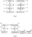
- Figure 3 shows an example of a device according to the invention for use in connection with verifying fixed safety volumes for movable mechanical units.
- the device comprises a portable display unit 5 including a screen for displaying augmented reality images.
- the screen is, for example, a touch screen or a transparent screen.
- the device further comprises a storage unit 10, such as RAM, ROM, PROM, EEPROM, configured to store descriptions of the fixed safety volumes.
- the descriptions are defined in relation to the world coordinate system.
- the descriptions include coordinates of safety volumes in the world coordinate system.
- the device may obtain descriptions of the fixed safety volumes from the safety system of the robot, from an off-line programming tool, or from a user interface to which a user feds the descriptions.
- the device further comprises a position detector 14 configured to continuously determine the position and orientation of the display unit 5. For example, the position detector 14 determines a position vector in relation to the world coordinate system for the portable display unit.
- the device further comprises a graphical unit 16 configured to determine graphical representations of the fixed safety volumes based on the stored descriptions of the fixed safety volumes and the position vector of the portable display unit 5.
- the device further comprises an augmented reality unit 18 configured to overlay the graphical representation of the safety volumes on a view of the real world to provide a composited augmented reality image, and to display the augmented reality image on the portable display unit 5.
- the storage unit 10, the position detector 14, the graphical unit 16, and the augmented reality unit 18 are implemented as a part of the portable display unit 5.
- the graphical unit 16 and the augmented reality unit 18 are software modules, which preferably are run on a processor of the display unit 5.
- the screen of the display unit 5 is opaque, i.e. not of see-through type
- the device further includes a camera 20 configured to capture an image of the real robot and its environment
- the augmented reality unit 18 is configured to register the graphical representations of the safety volumes on the image of the real robot and its environment to provide the composited augmented reality image.
- the display unit 5 visualizes the view of the camera 20 combined with computer generated graphics of the safety volumes.
- the camera 20 is preferably mounted on or integrated in the display unit 5. All types of cameras can be used, but the demand for accuracy of position and orientation determines the type of camera. For example, a web camera, a video camera, or a CCD camera could be used. However, the camera is optional. The camera is not necessary if see-through glasses are used and the position and orientation of the display unit are determined using any other type of sensor.
- the position detector 14 is configured to determine the position and orientation of the display unit 5 in relation to the world coordinate system.
- the position and orientation of the display unit can be tracked in a number of different ways.
- the position detector 14 is configured to determine the position vector of the display unit based on the images received from the camera 20.
- the position and orientation of the display unit is, for example, determined by image recognition.
- the display unit could be provided with a sensor for determining the position and orientation. Examples of sensors and technologies for determining positions and orientations are computer vision, inertial sensing, ultrasonic sensing, and magnetic sensing, accelerometers, gyros, laser technology, and Global Positioning System (GPS).
- GPS Global Positioning System
- the graphical unit 16 is configured to determine 2D graphical representations of the safety volumes based on the 3D descriptions of the safety volumes and the position vector of the portable display unit, and the augmented reality unit is configured to register the 2D graphical representations of the safety volumes on the image of the real robot and its environment to provide a composited augmented reality image.
- 3D graphical representations of the safety volumes are presented on the display unit.
- the device may include an interaction unit 22 configured to detect user interactions with the graphical representation of the fixed safety volumes, and a modification unit 24 configured to modify the stored description of the fixed safety volumes based on detected user interactions.
- the display unit may include a touch screen and the interaction unit detects user interactions with the graphical representation on the touch screen.
- the interaction can, for example, be made directly on the screen of the display unit, or by gestures in the air in front of a pair of interactive glasses.
- the user is allowed to move a point on the safety volume by drag and drop, and to enlarge and reduce the size of a safety volume by moving one or more fingers over the screen.
- This embodiment makes it possible for a user to modify fixed safety volumes on site during on-line verification of the safety volumes, and accordingly to reduce the time needed for verification and modification of the fixed safety volumes.
- the most widely adapted technology is marker tracking.
- This technology works by having the camera detect and track physical markers in the environment, and displaying virtual objects on the screen aligned to the markers.
- An advantage with this method is that it is easy to calculate the angle of the camera relative to the marker and align the virtual object accordingly, and it is simple to implement.
- Another technology which can be used is markerless AR.
- the markerless technology builds on the principle of natural feature tracking, which means that the device creates a visual understanding of an environment it had no previous knowledge of. This allows for new forms of AR applications where digital images are placed and aligned straight into the real environment without the need for physical markers.
- marker based and markerless AR technologies focus around the camera as the most important sensor
- geo-location based AR focuses on the positioning sensors of the device such as the GPS, accelerometer, compass and gyroscope.
- digital information of the safety volumes can be overlaid the real world to provide information position of the safety volume relative the robot and the surroundings.
- FIG 4 shows a block scheme of a method according to a first embodiment of the invention for verifying fixed safety volumes (FSV).
- a fixed safety volume has a fixed size and a fixed position in relation to the environment of the mechanical unit.
- the method described is based on the use of a camera arranged to provide images of the robot and its environment. However, other methods can be used.
- a world coordinate system is defined in relation to the mechanical unit and in relation to the environment of the mechanical unit.
- the verification is made in two steps. The second verification step is optional.
- the first step includes obtaining a description of each of the fixed safety volumes, block 30.
- the descriptions are preferably 3D descriptions.
- the descriptions are defined in relation to the world coordinate system.
- the descriptions are, for example, obtained from the safety system of the robot.
- the descriptions are stored in the storage unit 10, block 32.
- the first verification step further includes verifying the fixed safety volumes based on the displayed augmented reality image, block 44.
- the user moves the display unit around in a robot cell and looks at the environment and the safe volumes from different angles.
- the displayed augmented reality image provides the user with feedback on how and where in the robot environment the fixed safety volumes are defined.
- this step comprises detecting user interactions with the graphical representation of the fixed safety volume, and modifying the description of the fixed safety volume based on said detected user interactions.
- the interaction can, for example, be made directly on the screen of the display unit, or by gestures in the air in front of a pair of interactive glasses. Is it advantageous to run the first step again, block 34 - 44, after the fixed safety volumes have been modified to ensure that the modified safety volumes are correct. Steps 34 - 46 are repeated until the user determines that the verification is finished.
- a second verification step can be carried out.
- the robot is repeatedly moved in different directions until the robot reaches the borderlines of the fixed safety volumes, block 48.
- the robot can be automatically moved in accordance with a verification program.
- the fixed safety volumes are modified upon detecting an incorrect safety volume, block 50.
- the modified safety modules must be verified.
- the modified safety modules are verified by running the first and second verification step again.
- a moving safety volume is defined in relation to a critical part of the robot and has a variable size and position in relation to the environment of the robot.
- One or more moving safety volumes can be defined for one mechanical unit.
- the critical part is, for example, the Tool Centre Point (TCP) of a robot or an elbow of the robot.
- TCP Tool Centre Point
- the position of a moving safety volume depends on the position of the critical part, and the size of the moving safety volume depends on the current velocity and load of the critical part.
- the moving safety volume depends on a movement path of the robot. The moving safety volume follows the movements of the critical part along the movement path. The size of the moving safety volume is zero when the critical part stands still.
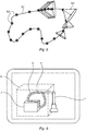
- Figure 5 shows an example of graphical presentation of a moving safety volume 60 along a movement path 62 defined by a plurality of target points 64.
- the position and velocity is known along the movement path 62.
- a braking distance i.e. safety distance.
- the braking distance can be represented as a volume, for example, in the form of a cone. This volume is denoted a moving safety volume. It is possible to determine a moving safety volume 60 along movement path 62. As seen in the figure the cones will "disappear” and instead be seen as a "tube”. This tube can then be visualized through augmented reality.
- the first term describes the distance travelled by the operator from the moment of detection until the robot system is halted
- the second term represents the distance travelled by the robot from the moment of detection until the engagement of stopping means
- the third term is the braking distance travelled by the robot during the halting process. Further information about the intrusion distance, C, can be found in ISO 13855.
- Figure 6 shows a block diagram of a device for verifying safety volumes according to a second embodiment of the invention.
- the storage unit 10 is adapted to store descriptions moving safety volumes.
- This device shown in figure 6 differs from the device shown in figure 3 in that it comprises a description generator 66 configured to obtain positions and velocities of critical parts of the mechanical unit, to determine moving safety volumes for critical parts of the mechanical unit based on the positions and velocities of the critical parts, and to store descriptions of the braking-movement volumes defined in relation to the world coordinate system in the storage unit 10.
- the graphical unit 16 is configured to determine graphical representations of the moving safety volumes based on the descriptions of the moving safety volumes, and the position and orientation of the portable display unit.
- the augmented reality unit 18 is configured to overlay the graphical representations of the movable safety volumes on a view of the real environment of the mechanical unit to provide a composited augmented reality image.
- a graphical presentation of the moving safety volume is presented in relation to the real environment of the robot. This embodiment enables a user to visually determine if there is any overlap between the moving safety volume and an obstacle in the environment of the mechanical unit. If there is an overlap between the moving safety volume and the obstacle, there is a risk for collision between the mechanical unit and the obstacle and the movement path has to be reprogrammed.
- the positions and velocities of the critical part are, for example, obtained from the robot controller 4.
- the robot program is then executed on the real robot while moving safety volumes for the critical part are determined based on the position, velocity, and optionally the load, of the real robot.
- the size and position of the moving safety volume is then determined based on the current position and velocity of the real robot.
- the positions and velocities of the critical part are obtained from a simulation unit 68 configured to simulate the programmed movement path for the mechanical unit.
- the size and position of the moving safety volume are then determined based on the position and velocity of the critical part obtained from the simulation. It is suitable to locate the simulation unit in the portable display unit.
- the simulation unit can also be located on a remote computer, on the robot controller, or in the safety system.
- This embodiment makes it possible to verify a programmed movement path with regard to collisions in the real environment of the mechanical unit without having to move the mechanical unit.
- the graphical presentation of the moving safety volume is moved along the programmed path in the real environment, while the mechanical unit stands still. Due to the fact that the mechanical unit does not have to be moved, it is safe for the user to walk around in the environment of the mechanical unit, and to detect overlap between the moving safety volume and obstacles in the environment.
- the device disclosed in figure 6 further comprises a simulation unit 68 configured to simulate the programmed movement path for the mechanical unit, and to determine the position and velocity of the critical part during execution of the movement path based on the simulation.
- the description generator 66 is configured to obtain the positions and velocities of the critical part along the movement path from the simulation unit 68 and to determine the moving safety volumes based on the obtained positions and velocities.
- the description generator 66 determines the braking distances along the path, for example, based on the velocity of the robot, the reaction time of the robot, and the mass of the robot and load carried by the robot.
- the storage unit 10 is adapted to store descriptions of the moving safety volumes as well as fixed safety volumes
- the graphical unit 16 is configured to determine graphical representations of the moving safety volumes as well as fixed safety volumes.
- FIG. 7 shows a block scheme of a method for verifying moving safety volumes (MSV) according to a second embodiment of the invention. It will be understood that each block of the flow chart can be implemented by computer program instructions.
- the method comprises repeatedly: Obtaining position and velocity of the critical part of the mechanical unit, block 52.
- the positions and velocities can be actual positions and velocities of the mechanical unit, or simulated values.
- This step includes determining the braking distance on the path based on the velocity of the mechanical unit. Storing a description of the moving safety volume defined in relation to the world-coordinate system, block 56.
- the description is, for example, the coordinates of the safety volume in the world-coordinate system. Determining position and orientation of a portable display unit in relation to the world-coordinate system, block 58. Determining a graphical representation of the moving safety volume based on the stored description of the moving safety volume and the position and orientation of the portable display unit, block 60. This means that a graphical presentation of the movable safety volume seen from the present position and angle of the display unit is determined.
- the graphical representation of the moving safety volumes is overlaid a view of the real environment of mechanical unit to provide a composited augmented reality image, block 62.
- the augmented reality image is displayed on the portable display unit, block 64.
- the method is repeated until moving safety volumes have been displayed along the entire path, block 66. It is possible to continue to display all moving safety volumes along the path as long as the user chooses.
- FIG. 8 shows a block scheme of a method for verifying fixed safety volumes according to a third embodiment of the invention. It will be understood that each block of the flow chart can be implemented by computer program instructions.
- One or more fixed safety volumes are defined for the movable mechanical unit in relation to the world coordinate system. Descriptions of the fixed safety volumes (FSV) defined in the world coordinate system are stored, block 70. Positions and velocities of a critical part of the mechanical unit are obtained, block 72. Moving safety volumes (MSV) for the critical part is determined along the entire path based on the obtained positions and velocities of the critical part 4. The descriptions of the moving safety volumes defined in the world coordinate system are stored, block 74.
- FSV fixed safety volumes
- MSV Moving safety volumes
- the present position and orientation of a portable display unit is determined in relation to the world-coordinate system, block 76.
- a graphical representation of the fixed and moving safety volumes are determined based on the stored descriptions of the fixed and moving safety volumes and the position and orientation of the portable display unit, block 78. This means that a graphical representation of the fixed and movable safety volumes as seen from the present position and angle of the display unit is determined.
- the graphical representation of the fixed and moving safety volumes is overlaid a view of the environment of mechanical unit to provide a composited augmented reality image, block 80.
- the augmented reality image is displayed on the portable display unit, block 82.
- the fixed and moving safety volumes are thereby visualized in the real environment of the robot.
- By displaying one or more fixed safety volumes simultaneously and in the same view as one or more moving safety volumes it is possible to visually verify the position of a fixed safety volume in relation to the movement path.
- a user it is possible for a user to detect improvements of the fixed safety volumes and make necessary modifications of the fixed safety volume. For example, if the robot is only allowed to move inside the fixed safety volume and the distance between the fixed safety volume and the moving volume is large along the entire path, the size of the fixed safety volume can be reduced and thereby a higher utilization of the space in a factory can be achieved.
- the method may include the steps of detecting user interactions with the graphical representation of the fixed safety volume, block 84, and modifying the description of the fixed safety volume based on said detected user interactions, 86.
- a user may modify the shape and position of the fixed safety volume during verification of the safety volumes, for example, by interacting with a touch screen on the display unit.
- the steps in blocks 76 - 86 are repeated until the user has finished the verification, block 88.
- the second verification step previously described can be carried out.
- Figure 9 shows an example of an augmented reality image including a graphical representation of a fixed safety volume 6 and a moving safety volume 9 presented on top of a real robot cell disclosed in figure 1 .
- the fixed safety volume 6 is shaped as a cuboid and the moving safety volume 9 is tube shaped.
- the moving safety volume 9 encloses a programmed movement path 11.
- the present invention is not limited to the embodiments disclosed but may be varied and modified within the scope of the following claims.
- the graphical unit and/or the augmented reality unit can be located outside the portable display unit, for instance, on an external server or as a cloud service.
- the simulator unit can also be located outside the portable display unit, for instance, on the robot controller, or an external server.
Landscapes
- Engineering & Computer Science (AREA)
- Robotics (AREA)
- Mechanical Engineering (AREA)
- Human Computer Interaction (AREA)
- Manufacturing & Machinery (AREA)
- Physics & Mathematics (AREA)
- General Physics & Mathematics (AREA)
- Automation & Control Theory (AREA)
- Processing Or Creating Images (AREA)
- User Interface Of Digital Computer (AREA)
Claims (15)
- Verfahren zur Überprüfung eines oder mehrerer Sicherheitsvolumen (6; 9; 60) für eine bewegliche mechanische Einheit (1) in Bezug auf eine Umgebung der mechanischen Einheit, wobei ein Weltkoordinatensystem (x, y, z) im Verhältnis zu der mechanischen Einheit und im Verhältnis zu der Umgebung der mechanischen Einheit definiert ist, dadurch gekennzeichnet, dass das Verfahren Folgendes umfasst:- Speichern einer Beschreibung von einem oder mehreren Sicherheitsvolumen, das/die im Verhältnis zu dem Weltkoordinatensystem definiert ist/sind, und wiederholtes:- Bestimmen einer Position und einer Ausrichtung einer tragbaren Anzeigeeinheit (5) im Verhältnis zu dem Weltkoordinatensystem,- Bestimmen einer grafischen Darstellung der Sicherheitsvolumen basierend auf der Beschreibung der Sicherheitsvolumen und der Position und der Ausrichtung der tragbaren Anzeigeeinheit,- Überlagern der grafischen Darstellung der Sicherheitsvolumen auf eine Ansicht der realen Umgebung der mechanischen Einheit zum Bereitstellen eines zusammengesetzten Augmented-Reality-Bildes, und- Anzeigen des Augmented-Reality-Bildes auf der tragbaren Anzeigeeinheit.
- Verfahren nach Anspruch 1, wobei mindestens eines der Sicherheitsvolumen ein feststehendes Sicherheitsvolumen (6) mit einer festen Position im Verhältnis zu dem Weltkoordinatensystem ist.
- Verfahren nach Anspruch 1 oder 2, wobei das Verfahren das Überprüfen des feststehenden Sicherheitsvolumens (6) basierend auf dem angezeigten Augmented-Reality-Bild und das Modifizieren des feststehenden Sicherheitsvolumens bei Erkennung eines inkorrekten Sicherheitsvolumens umfasst.
- Verfahren nach Anspruch 2 oder 3, wobei das Verfahren das Erkennen von Benutzerinteraktionen mit der grafischen Darstellung des feststehenden Sicherheitsvolumens und das Modifizieren der Beschreibung des feststehenden Sicherheitsvolumens basierend auf den erkannten Benutzerinteraktionen umfasst.
- Verfahren nach einem der vorhergehenden Ansprüche, wobei mindestens eines der Sicherheitsvolumen (60; 9) ein bewegliches Sicherheitsvolumen ist, das eine Größe und eine Position aufweist, die von der Geschwindigkeit und der Position eines kritischen Teils (TCP) der mechanischen Einheit abhängt, und das Verfahren wiederholt Folgendes umfasst:- Erhalten einer Position und einer Geschwindigkeit des kritischen Teils der mechanischen Einheit,- Bestimmen des beweglichen Sicherheitsvolumens für den kritischen Teil der mechanischen Einheit basierend auf der Position und der Geschwindigkeit des kritischen Teils, und- Speichern einer Beschreibung des beweglichen Sicherheitsvolumens, das im Verhältnis zu dem Weltkoordinatensystem definiert ist.
- Verfahren nach Anspruch 5, wobei das Verfahren Folgendes umfasst:- Simulieren eines programmierten Bewegungspfades für die mechanische Einheit,- Bestimmen einer Position und einer Geschwindigkeit des kritischen Teils entlang des Bewegungspfades basierend auf der Simulation, und- Bestimmen des beweglichen Sicherheitsvolumens basierend auf der bestimmten Position und Geschwindigkeit des kritischen Teils.
- Verfahren nach Anspruch 5 oder 6, wobei das Verfahren Folgendes umfasst:- Berechnen eines Sicherheitsabstandes für den kritischen Teil basierend auf der Geschwindigkeit und der Last des kritischen Teils, und- Bestimmen des beweglichen Sicherheitsvolumens basierend auf dem berechneten Sicherheitsabstand.
- Verfahren nach einem der vorhergehenden Ansprüche, wobei mindestens eines der Sicherheitsvolumen ein feststehendes Sicherheitsvolumen ist und mindestens eines der Sicherheitsvolumen ein bewegliches Sicherheitsvolumen ist, und das Verfahren wiederholt Folgendes umfasst:- Bestimmen einer grafischen Darstellung jedes des feststehenden Sicherheitsvolumens (6) und des beweglichen Sicherheitsvolumens (60; 9) basierend auf den Beschreibungen der Sicherheitsvolumen und der Position und der Ausrichtung der tragbaren Anzeigeeinheit,- Überlagern der grafischen Darstellung des feststehenden Sicherheitsvolumens und des beweglichen Sicherheitsvolumens auf die reale Ansicht der Umgebung zum Bereitstellen eines zusammengesetzten Augmented-Reality-Bildes, und- Anzeigen des Augmented-Reality-Bildes auf der tragbaren Anzeigeeinheit.
- Vorrichtung zur Überprüfung eines oder mehrerer Sicherheitsvolumen (6; 9; 60) für mindestens eine bewegliche mechanische Einheit (1), die in einer Umgebung positioniert ist, wobei ein Weltkoordinatensystem (x, y, z) im Verhältnis zu der mechanischen Einheit und im Verhältnis zu der Umgebung der mechanischen Einheit definiert ist, dadurch gekennzeichnet, dass die Vorrichtung Folgendes umfasst:- eine Speichereinheit (10) zum Speichern von Beschreibungen der Sicherheitsvolumen,- eine tragbare Anzeigeeinheit (5),- einen Positionsdetektor (14), der konfiguriert ist zum kontinuierlichen Bestimmen der Position und der Ausrichtung der tragbaren Anzeigeeinheit im Verhältnis zu dem Weltkoordinatensystem,- eine Grafikeinheit (16), die konfiguriert ist zum Bestimmen grafischer Darstellungen der Sicherheitsvolumen basierend auf den gespeicherten Beschreibungen der Sicherheitsvolumen und der Position und der Ausrichtung der tragbaren Anzeigeeinheit, und- eine Augmented-Reality-Einheit (18), die konfiguriert ist zum Überlagern der grafischen Darstellungen der Sicherheitsvolumen auf eine Ansicht der realen Umgebung einer mechanischen Einheit zum Bereitstellen eines zusammengesetzten Augmented-Reality-Bildes und zum Anzeigen des Augmented-Reality-Bildes auf der tragbaren Anzeigeeinheit.
- Vorrichtung nach Anspruch 9, wobei die Vorrichtung einen Beschreibungsgenerator (66) umfasst, der konfiguriert ist zum Erhalten von Positionen und Geschwindigkeiten eines kritischen Teils der mechanischen Einheit, zum Bestimmen beweglicher Sicherheitsvolumen für den kritischen Teil der mechanischen Einheit basierend auf den Positionen und Geschwindigkeiten des kritischen Teils und zum Speichern einer Beschreibung des beweglichen Sicherheitsvolumens, das im Verhältnis zu dem Weltkoordinatensystem in der Speichereinheit definiert ist.
- Vorrichtung nach Anspruch 10, wobei die Vorrichtung eine Simulationseinheit (68) umfasst, die konfiguriert ist zum Simulieren eines programmierten Bewegungspfades für die mechanische Einheit und zum Bestimmen der Position und der Geschwindigkeit des kritischen Teils während einer Ausführung des Bewegungspfades basierend auf der Simulation, und der Beschreibungsgenerator (66) konfiguriert ist zum Erhalten der Position und der Geschwindigkeit des kritischen Teils von der Simulationseinheit und zum Bestimmen des beweglichen Sicherheitsvolumens basierend auf der erhaltenen Position und Geschwindigkeit.
- Vorrichtung nach Anspruch 10 oder 11, wobei die Speichereinheit (10) konfiguriert ist zum Speichern von Beschreibungen von feststehenden Sicherheitsvolumen, die eine feststehende Position im Verhältnis zu dem Weltkoordinatensystem aufweisen, wobei die Grafikeinheit (16) konfiguriert ist zum Bestimmen von grafischen Darstellungen der feststehenden Sicherheitsvolumen und der beweglichen Sicherheitsvolumen basierend auf den Beschreibungen der Sicherheitsvolumen und der Position und der Ausrichtung der tragbaren Anzeigeeinheit, und die Augmented-Reality-Einheit (18) konfiguriert ist zum Überlagern der grafischen Darstellungen der feststehenden und beweglichen Sicherheitsvolumen auf die Ansicht der realen mechanischen Einheit und ihrer Umgebung zum Bereitstellen eines zusammengesetzten Augmented-Reality-Bildes.
- Vorrichtung nach einem der Ansprüche 9 - 12, wobei die Speichereinheit (10) konfiguriert ist zum Speichern von Beschreibungen feststehender Sicherheitsvolumen, die eine feststehende Position im Verhältnis zu dem Weltkoordinatensystem aufweisen, und die Vorrichtung eine Interaktionseinheit (22), die konfiguriert ist zum Erkennen von Benutzerinteraktionen mit den grafischen Darstellungen der feststehenden Sicherheitsvolumen, und eine Modifikationseinheit (24), die konfiguriert ist zum Modifizieren der gespeicherten Beschreibung der feststehenden Sicherheitsvolumen basierend auf den erkannten Benutzerinteraktionen, umfasst.
- Vorrichtung nach einem der Ansprüche 9 - 13, wobei die Vorrichtung eine Kamera (20) umfasst, die konfiguriert ist zum Aufnehmen eines Bildes der mechanischen Einheit und ihrer Umgebung, und die Augmented-Reality-Einheit (18) konfiguriert ist zum Registrieren der grafischen Darstellungen der Sicherheitsvolumen auf dem Bild der realen mechanischen Einheit und ihrer Umgebung zum Bereitstellen eines zusammengesetzten Augmented-Reality-Bildes.
- Verwendung der Vorrichtung nach einem der Ansprüche 9 - 14 zur Überprüfung von Sicherheitsvolumen für einen Industrieroboter.
Applications Claiming Priority (1)
| Application Number | Priority Date | Filing Date | Title |
|---|---|---|---|
| PCT/EP2013/070773 WO2015051815A1 (en) | 2013-10-07 | 2013-10-07 | A method and a device for verifying one or more safety volumes for a movable mechanical unit |
Publications (2)
| Publication Number | Publication Date |
|---|---|
| EP3055744A1 EP3055744A1 (de) | 2016-08-17 |
| EP3055744B1 true EP3055744B1 (de) | 2018-06-13 |
Family
ID=49304967
Family Applications (1)
| Application Number | Title | Priority Date | Filing Date |
|---|---|---|---|
| EP13773739.1A Active EP3055744B1 (de) | 2013-10-07 | 2013-10-07 | Verfahren und vorrichtung zur überprüfung einer oder mehrerer sicherheitsvolumen für eine bewegliche mechanische einheit |
Country Status (5)
| Country | Link |
|---|---|
| US (1) | US10888998B2 (de) |
| EP (1) | EP3055744B1 (de) |
| CN (1) | CN105637435B (de) |
| ES (1) | ES2680576T3 (de) |
| WO (1) | WO2015051815A1 (de) |
Cited By (2)
| Publication number | Priority date | Publication date | Assignee | Title |
|---|---|---|---|---|
| DE102018109463B3 (de) | 2018-04-19 | 2019-09-19 | Yuanda Robotics Gmbh | Verfahren zur Benutzung einer mehrgliedrigen aktuierten Kinematik, vorzugsweise eines Roboters, besonders vorzugsweise eines Knickarmroboters, durch einen Benutzer mittels einer mobilen Anzeigevorrichtung |
| DE102023118992B3 (de) | 2023-07-18 | 2024-08-29 | Hochschule Bielefeld, Körperschaft des Öffentlichen Rechts | System und Verfahren zur Eingabe von virtuellen Objekten in drei Dimensionen mittels Augmented Reality zum Ermitteln des Bewegungsraums für Roboter |
Families Citing this family (43)
| Publication number | Priority date | Publication date | Assignee | Title |
|---|---|---|---|---|
| CN105960623B (zh) * | 2014-04-04 | 2019-02-05 | Abb瑞士股份有限公司 | 用于控制机器人的便携式装置及其方法 |
| DE102014005030A1 (de) * | 2014-04-05 | 2015-10-08 | Airbus Defence and Space GmbH | Testvorrichtung für Sichtsysteme |
| JP2016107379A (ja) * | 2014-12-08 | 2016-06-20 | ファナック株式会社 | 拡張現実対応ディスプレイを備えたロボットシステム |
| EP3292060B1 (de) * | 2015-05-04 | 2025-12-17 | Mitutoyo Corporation | Bearbeitungsumgebung eines prüfprogramms mit bereitstellung von benutzerdefinierten kollisionsvermeidungsvolumina |
| JP6690203B2 (ja) * | 2015-11-25 | 2020-04-28 | 株式会社デンソーウェーブ | ロボット安全システム |
| US9855664B2 (en) * | 2015-11-25 | 2018-01-02 | Denso Wave Incorporated | Robot safety system |
| KR102431194B1 (ko) * | 2015-12-11 | 2022-08-11 | 한화디펜스 주식회사 | 객체 이동 경로를 이용한 장애물 충돌 여부 판단 방법 및 이를 위한 장치 |
| AT518498B1 (de) | 2016-03-29 | 2018-09-15 | B & R Ind Automation Gmbh | Positionsüberwachung einer Kinematik |
| US10956739B2 (en) * | 2016-06-27 | 2021-03-23 | Autodesk, Inc. | Augmented reality robotic system visualization |
| JP2018008347A (ja) * | 2016-07-13 | 2018-01-18 | 東芝機械株式会社 | ロボットシステムおよび動作領域表示方法 |
| US10684480B2 (en) * | 2017-03-16 | 2020-06-16 | Denso Wave Incorporated | Information display system |
| JP2018171668A (ja) * | 2017-03-31 | 2018-11-08 | セイコーエプソン株式会社 | 制御装置、ロボット、およびロボットシステム |
| JP6870433B2 (ja) * | 2017-03-31 | 2021-05-12 | セイコーエプソン株式会社 | 制御装置、およびロボットシステム |
| JP6445092B2 (ja) | 2017-05-31 | 2018-12-26 | ファナック株式会社 | ロボットの教示のための情報を表示するロボットシステム |
| JP6538760B2 (ja) | 2017-06-22 | 2019-07-03 | ファナック株式会社 | 複合現実シミュレーション装置及び複合現実シミュレーションプログラム |
| JP7329902B2 (ja) * | 2017-08-25 | 2023-08-21 | オムロン株式会社 | ロボット制御装置、ロボットシステム、ロボット制御方法、および、ロボット制御プログラム |
| US10981272B1 (en) * | 2017-12-18 | 2021-04-20 | X Development Llc | Robot grasp learning |
| DE102018202321A1 (de) * | 2018-02-15 | 2019-08-22 | Robert Bosch Gmbh | Koordinierungsanlage, Handhabungseinrichtung und Verfahren |
| CN108481323B (zh) * | 2018-03-14 | 2021-04-27 | 清华大学天津高端装备研究院洛阳先进制造产业研发基地 | 基于增强现实的机器人运动轨迹自动编程系统及方法 |
| US20190299409A1 (en) * | 2018-03-29 | 2019-10-03 | Siemens Industry Software Ltd. | Method, system and computer program product for determining tuned robotic motion instructions |
| US10503143B1 (en) * | 2018-04-05 | 2019-12-10 | Amazon Technologies, Inc. | Protection system for multi-zone robotic area |
| EP3566824B1 (de) * | 2018-05-11 | 2023-06-28 | Siemens Aktiengesellschaft | Verfahren, vorrichtung, computerlesbare speichermedien und computerprogramm zur roboterprogrammierung |
| EP3578320B1 (de) | 2018-06-07 | 2021-09-15 | Sick Ag | Konfigurieren einer von einem 3d-sensor überwachten gefahrenstelle |
| WO2020006146A1 (en) * | 2018-06-26 | 2020-01-02 | Fanuc America Corporation | Augmented reality visualization for robotic picking system |
| JP7419271B2 (ja) * | 2018-06-26 | 2024-01-22 | ファナック アメリカ コーポレイション | 拡張現実を使用した操作上の境界ゾーンの視覚化と変更 |
| US11169601B2 (en) * | 2018-07-12 | 2021-11-09 | Toyota Research Institute, Inc. | Methods and systems for determining teleoperating user intent via eye tracking |
| JP7167518B2 (ja) * | 2018-07-20 | 2022-11-09 | セイコーエプソン株式会社 | 制御装置、ヘッドマウントディスプレイおよびロボットシステム |
| DE112019004519T5 (de) * | 2018-09-10 | 2021-06-02 | Fanuc America Corporation | Null-einlernen für roboterbahnsteuerung |
| DE102018218828A1 (de) * | 2018-11-05 | 2020-05-07 | Kuka Systems Gmbh | Verfahren und System zum Modifizieren eines Arbeitsprozesses in einer Maschinenanlage und/oder eines virtuellen 3D-Modells der Maschinenanlage |
| JP6895128B2 (ja) * | 2018-11-09 | 2021-06-30 | オムロン株式会社 | ロボット制御装置、シミュレーション方法、及びシミュレーションプログラム |
| DE102019103349B3 (de) * | 2019-02-11 | 2020-06-18 | Beckhoff Automation Gmbh | Industrierobotersystem und Verfahren zur Steuerung eines Industrieroboters |
| TR201905154A2 (tr) * | 2019-04-05 | 2020-10-21 | Jeanologia Teknoloji A S | Atalet ölçüm üni̇tesi̇ (imu) ve telli̇ kodlayici konum sensörleri̇ kullanilan üç boyutlu pozi̇syon ve oryantasyon hesaplama ve roboti̇k uygulamasi terti̇bati |
| US11694432B2 (en) * | 2019-07-23 | 2023-07-04 | Toyota Research Institute, Inc. | System and method for augmenting a visual output from a robotic device |
| CA3169555A1 (en) * | 2020-03-06 | 2021-09-10 | Patrick Forrest | Computer enhanced safety system |
| WO2021228382A1 (en) * | 2020-05-13 | 2021-11-18 | Abb Schweiz Ag | Policy-restricted execution of a robot program with movement instructions |
| DE102020129823B4 (de) * | 2020-11-12 | 2022-07-07 | Sick Ag | Visualisieren eines Schutzfeldes |
| US11794345B2 (en) * | 2020-12-31 | 2023-10-24 | Sarcos Corp. | Unified robotic vehicle systems and methods of control |
| JP7707584B2 (ja) | 2021-03-12 | 2025-07-15 | オムロン株式会社 | 情報処理装置および情報処理方法、並びにプログラム |
| CN113459112B (zh) * | 2021-09-03 | 2021-12-17 | 成都卡诺普机器人技术股份有限公司 | 一种机器人与外部轴协同的方法及装置 |
| US20240408760A1 (en) * | 2021-10-19 | 2024-12-12 | Abb Schweiz Ag | Method of Handling Safety of Industrial Robot, Control System and Robot System |
| WO2023131385A1 (en) * | 2022-01-10 | 2023-07-13 | Universal Robots A/S | Augmented reality supported safety plane adjustment |
| CN119212831A (zh) * | 2022-03-15 | 2024-12-27 | 库卡德国有限公司 | 确定机器人运行的至少一个边界 |
| US20250303573A1 (en) * | 2024-03-28 | 2025-10-02 | Honda Motor Co., Ltd. | Change and attention-based scene extraction |
Family Cites Families (13)
| Publication number | Priority date | Publication date | Assignee | Title |
|---|---|---|---|---|
| US20020133264A1 (en) * | 2001-01-26 | 2002-09-19 | New Jersey Institute Of Technology | Virtual reality system for creation of design models and generation of numerically controlled machining trajectories |
| NO317898B1 (no) | 2002-05-24 | 2004-12-27 | Abb Research Ltd | Fremgangsmate og system for a programmere en industrirobot |
| SE531104C2 (sv) | 2002-12-30 | 2008-12-16 | Abb Research Ltd | Metod och system för programmering av en industrirobot |
| DE10305384A1 (de) * | 2003-02-11 | 2004-08-26 | Kuka Roboter Gmbh | Verfahren und Vorrichtung zur Visualisierung rechnergestützter Informationen |
| SE526119C2 (sv) | 2003-11-24 | 2005-07-05 | Abb Research Ltd | Metod och system för programmering av en industrirobot |
| US8225226B2 (en) | 2003-12-31 | 2012-07-17 | Abb Research Ltd. | Virtual control panel |
| US7236854B2 (en) | 2004-01-05 | 2007-06-26 | Abb Research Ltd. | Method and a system for programming an industrial robot |
| DE102005061211B4 (de) | 2004-12-22 | 2023-04-06 | Abb Schweiz Ag | Verfahren zum Erzeugen einer Mensch-Maschine-Benutzer-Oberfläche |
| DE102006014634B4 (de) | 2005-04-01 | 2014-01-30 | Abb Research Ltd. | Mensch-Maschine-Schnittstelle für ein Kontroll- bzw. Steuerungs-System |
| DE502006009264D1 (de) | 2006-09-30 | 2011-05-19 | Abb Technology Ag | Verfahren und System zur Auslegung und Überprüfung von Sicherheitsbereichen eines Roboters |
| WO2011080882A1 (ja) * | 2009-12-28 | 2011-07-07 | パナソニック株式会社 | 動作空間提示装置、動作空間提示方法およびプログラム |
| US9554866B2 (en) | 2011-08-09 | 2017-01-31 | Covidien Lp | Apparatus and method for using a remote control system in surgical procedures |
| DE102012110508B4 (de) * | 2011-11-04 | 2022-05-12 | Fanuc Robotics America Corp. | Roboter Einstellvorrichtung mit 3-D Display |
-
2013
- 2013-10-07 EP EP13773739.1A patent/EP3055744B1/de active Active
- 2013-10-07 US US14/914,695 patent/US10888998B2/en active Active
- 2013-10-07 WO PCT/EP2013/070773 patent/WO2015051815A1/en not_active Ceased
- 2013-10-07 CN CN201380080017.6A patent/CN105637435B/zh active Active
- 2013-10-07 ES ES13773739.1T patent/ES2680576T3/es active Active
Non-Patent Citations (1)
| Title |
|---|
| None * |
Cited By (3)
| Publication number | Priority date | Publication date | Assignee | Title |
|---|---|---|---|---|
| DE102018109463B3 (de) | 2018-04-19 | 2019-09-19 | Yuanda Robotics Gmbh | Verfahren zur Benutzung einer mehrgliedrigen aktuierten Kinematik, vorzugsweise eines Roboters, besonders vorzugsweise eines Knickarmroboters, durch einen Benutzer mittels einer mobilen Anzeigevorrichtung |
| DE102018109463C5 (de) | 2018-04-19 | 2023-10-05 | Voraus Robotik Gmbh | Verfahren zur Benutzung einer mehrgliedrigen aktuierten Kinematik, vorzugsweise eines Roboters, besonders vorzugsweise eines Knickarmroboters, durch einen Benutzer mittels einer mobilen Anzeigevorrichtung |
| DE102023118992B3 (de) | 2023-07-18 | 2024-08-29 | Hochschule Bielefeld, Körperschaft des Öffentlichen Rechts | System und Verfahren zur Eingabe von virtuellen Objekten in drei Dimensionen mittels Augmented Reality zum Ermitteln des Bewegungsraums für Roboter |
Also Published As
| Publication number | Publication date |
|---|---|
| US20160207198A1 (en) | 2016-07-21 |
| CN105637435A (zh) | 2016-06-01 |
| CN105637435B (zh) | 2018-04-17 |
| US10888998B2 (en) | 2021-01-12 |
| WO2015051815A1 (en) | 2015-04-16 |
| EP3055744A1 (de) | 2016-08-17 |
| ES2680576T3 (es) | 2018-09-10 |
Similar Documents
| Publication | Publication Date | Title |
|---|---|---|
| EP3055744B1 (de) | Verfahren und vorrichtung zur überprüfung einer oder mehrerer sicherheitsvolumen für eine bewegliche mechanische einheit | |
| US11850755B2 (en) | Visualization and modification of operational bounding zones using augmented reality | |
| US11396100B2 (en) | Robot calibration for AR and digital twin | |
| JP7442278B2 (ja) | 工業用拡張現実アプリケーションのためのドリフト補正 | |
| US11724388B2 (en) | Robot controller and display device using augmented reality and mixed reality | |
| JP6853280B2 (ja) | 拡張現実ロボットシステムの可視化 | |
| EP1629366B1 (de) | Einkamerasystem für die auf gesten basierende eingabe und zielanzeige | |
| EP1435280B1 (de) | Verfahren und Vorrichtung zum Programmieren eines Industrieroboters | |
| JP4508252B2 (ja) | ロボット教示装置 | |
| US11731283B2 (en) | Method for checking a safety area of a robot | |
| CN108089553B (zh) | 用于启动多轴系统的方法和装置 | |
| JP2004243516A (ja) | コンピュータによって生成された情報を現実環境の画像へとフェードインするための方法、およびコンピュータによって生成された情報を現実環境の画像に視覚化するための装置 | |
| JP2024500740A (ja) | オブジェクトの選択の方法及びシステム | |
| CN104802186A (zh) | 制作用于拍摄工件的机器人程序的机器人程序设计装置 | |
| WO2019186551A1 (en) | Augmented reality for industrial robotics | |
| CN108081267B (zh) | 用于启动多轴系统的方法和装置 | |
| KR20210068383A (ko) | 생산 라인에서의 작업자 위치 인식 방법 및 그 장치 | |
| CN113597362A (zh) | 用于确定机器人坐标系与可移动装置坐标系之间的关系的方法和控制装置 | |
| JP2020011357A (ja) | 制御装置、ヘッドマウントディスプレイおよびロボットシステム | |
| Ziaei et al. | Real-time markerless Augmented Reality for Remote Handling system in bad viewing conditions | |
| US12539607B2 (en) | Robot programming | |
| JP2022178396A (ja) | 誘導型遠隔操作方法及び装置 | |
| JP2022186476A (ja) | 情報処理装置、情報処理方法、及び、コンピュータプログラム | |
| US20250073908A1 (en) | Augmented reality supported safety plane adjustment |
Legal Events
| Date | Code | Title | Description |
|---|---|---|---|
| PUAI | Public reference made under article 153(3) epc to a published international application that has entered the european phase |
Free format text: ORIGINAL CODE: 0009012 |
|
| 17P | Request for examination filed |
Effective date: 20160509 |
|
| AK | Designated contracting states |
Kind code of ref document: A1 Designated state(s): AL AT BE BG CH CY CZ DE DK EE ES FI FR GB GR HR HU IE IS IT LI LT LU LV MC MK MT NL NO PL PT RO RS SE SI SK SM TR |
|
| AX | Request for extension of the european patent |
Extension state: BA ME |
|
| DAX | Request for extension of the european patent (deleted) | ||
| RAP1 | Party data changed (applicant data changed or rights of an application transferred) |
Owner name: ABB SCHWEIZ AG |
|
| GRAP | Despatch of communication of intention to grant a patent |
Free format text: ORIGINAL CODE: EPIDOSNIGR1 |
|
| RIC1 | Information provided on ipc code assigned before grant |
Ipc: B25J 9/16 20060101ALI20180119BHEP Ipc: G05B 19/4061 20060101AFI20180119BHEP |
|
| INTG | Intention to grant announced |
Effective date: 20180222 |
|
| RIN1 | Information on inventor provided before grant (corrected) |
Inventor name: MELLANDER, ROGER Inventor name: WILLFOER, PER Inventor name: KULLAENG, ROGER |
|
| GRAS | Grant fee paid |
Free format text: ORIGINAL CODE: EPIDOSNIGR3 |
|
| GRAA | (expected) grant |
Free format text: ORIGINAL CODE: 0009210 |
|
| AK | Designated contracting states |
Kind code of ref document: B1 Designated state(s): AL AT BE BG CH CY CZ DE DK EE ES FI FR GB GR HR HU IE IS IT LI LT LU LV MC MK MT NL NO PL PT RO RS SE SI SK SM TR |
|
| REG | Reference to a national code |
Ref country code: GB Ref legal event code: FG4D |
|
| REG | Reference to a national code |
Ref country code: CH Ref legal event code: EP Ref country code: AT Ref legal event code: REF Ref document number: 1009103 Country of ref document: AT Kind code of ref document: T Effective date: 20180615 |
|
| REG | Reference to a national code |
Ref country code: IE Ref legal event code: FG4D |
|
| REG | Reference to a national code |
Ref country code: DE Ref legal event code: R096 Ref document number: 602013038937 Country of ref document: DE |
|
| REG | Reference to a national code |
Ref country code: ES Ref legal event code: FG2A Ref document number: 2680576 Country of ref document: ES Kind code of ref document: T3 Effective date: 20180910 |
|
| REG | Reference to a national code |
Ref country code: NL Ref legal event code: MP Effective date: 20180613 |
|
| REG | Reference to a national code |
Ref country code: FR Ref legal event code: PLFP Year of fee payment: 6 |
|
| REG | Reference to a national code |
Ref country code: LT Ref legal event code: MG4D |
|
| PG25 | Lapsed in a contracting state [announced via postgrant information from national office to epo] |
Ref country code: BG Free format text: LAPSE BECAUSE OF FAILURE TO SUBMIT A TRANSLATION OF THE DESCRIPTION OR TO PAY THE FEE WITHIN THE PRESCRIBED TIME-LIMIT Effective date: 20180913 Ref country code: SE Free format text: LAPSE BECAUSE OF FAILURE TO SUBMIT A TRANSLATION OF THE DESCRIPTION OR TO PAY THE FEE WITHIN THE PRESCRIBED TIME-LIMIT Effective date: 20180613 Ref country code: FI Free format text: LAPSE BECAUSE OF FAILURE TO SUBMIT A TRANSLATION OF THE DESCRIPTION OR TO PAY THE FEE WITHIN THE PRESCRIBED TIME-LIMIT Effective date: 20180613 Ref country code: NO Free format text: LAPSE BECAUSE OF FAILURE TO SUBMIT A TRANSLATION OF THE DESCRIPTION OR TO PAY THE FEE WITHIN THE PRESCRIBED TIME-LIMIT Effective date: 20180913 Ref country code: CY Free format text: LAPSE BECAUSE OF FAILURE TO SUBMIT A TRANSLATION OF THE DESCRIPTION OR TO PAY THE FEE WITHIN THE PRESCRIBED TIME-LIMIT Effective date: 20180613 Ref country code: LT Free format text: LAPSE BECAUSE OF FAILURE TO SUBMIT A TRANSLATION OF THE DESCRIPTION OR TO PAY THE FEE WITHIN THE PRESCRIBED TIME-LIMIT Effective date: 20180613 |
|
| PG25 | Lapsed in a contracting state [announced via postgrant information from national office to epo] |
Ref country code: GR Free format text: LAPSE BECAUSE OF FAILURE TO SUBMIT A TRANSLATION OF THE DESCRIPTION OR TO PAY THE FEE WITHIN THE PRESCRIBED TIME-LIMIT Effective date: 20180914 Ref country code: HR Free format text: LAPSE BECAUSE OF FAILURE TO SUBMIT A TRANSLATION OF THE DESCRIPTION OR TO PAY THE FEE WITHIN THE PRESCRIBED TIME-LIMIT Effective date: 20180613 Ref country code: LV Free format text: LAPSE BECAUSE OF FAILURE TO SUBMIT A TRANSLATION OF THE DESCRIPTION OR TO PAY THE FEE WITHIN THE PRESCRIBED TIME-LIMIT Effective date: 20180613 Ref country code: RS Free format text: LAPSE BECAUSE OF FAILURE TO SUBMIT A TRANSLATION OF THE DESCRIPTION OR TO PAY THE FEE WITHIN THE PRESCRIBED TIME-LIMIT Effective date: 20180613 |
|
| REG | Reference to a national code |
Ref country code: AT Ref legal event code: MK05 Ref document number: 1009103 Country of ref document: AT Kind code of ref document: T Effective date: 20180613 |
|
| PG25 | Lapsed in a contracting state [announced via postgrant information from national office to epo] |
Ref country code: NL Free format text: LAPSE BECAUSE OF FAILURE TO SUBMIT A TRANSLATION OF THE DESCRIPTION OR TO PAY THE FEE WITHIN THE PRESCRIBED TIME-LIMIT Effective date: 20180613 |
|
| PG25 | Lapsed in a contracting state [announced via postgrant information from national office to epo] |
Ref country code: RO Free format text: LAPSE BECAUSE OF FAILURE TO SUBMIT A TRANSLATION OF THE DESCRIPTION OR TO PAY THE FEE WITHIN THE PRESCRIBED TIME-LIMIT Effective date: 20180613 Ref country code: CZ Free format text: LAPSE BECAUSE OF FAILURE TO SUBMIT A TRANSLATION OF THE DESCRIPTION OR TO PAY THE FEE WITHIN THE PRESCRIBED TIME-LIMIT Effective date: 20180613 Ref country code: EE Free format text: LAPSE BECAUSE OF FAILURE TO SUBMIT A TRANSLATION OF THE DESCRIPTION OR TO PAY THE FEE WITHIN THE PRESCRIBED TIME-LIMIT Effective date: 20180613 Ref country code: AT Free format text: LAPSE BECAUSE OF FAILURE TO SUBMIT A TRANSLATION OF THE DESCRIPTION OR TO PAY THE FEE WITHIN THE PRESCRIBED TIME-LIMIT Effective date: 20180613 Ref country code: IS Free format text: LAPSE BECAUSE OF FAILURE TO SUBMIT A TRANSLATION OF THE DESCRIPTION OR TO PAY THE FEE WITHIN THE PRESCRIBED TIME-LIMIT Effective date: 20181013 Ref country code: PL Free format text: LAPSE BECAUSE OF FAILURE TO SUBMIT A TRANSLATION OF THE DESCRIPTION OR TO PAY THE FEE WITHIN THE PRESCRIBED TIME-LIMIT Effective date: 20180613 Ref country code: SK Free format text: LAPSE BECAUSE OF FAILURE TO SUBMIT A TRANSLATION OF THE DESCRIPTION OR TO PAY THE FEE WITHIN THE PRESCRIBED TIME-LIMIT Effective date: 20180613 |
|
| PG25 | Lapsed in a contracting state [announced via postgrant information from national office to epo] |
Ref country code: SM Free format text: LAPSE BECAUSE OF FAILURE TO SUBMIT A TRANSLATION OF THE DESCRIPTION OR TO PAY THE FEE WITHIN THE PRESCRIBED TIME-LIMIT Effective date: 20180613 Ref country code: IT Free format text: LAPSE BECAUSE OF FAILURE TO SUBMIT A TRANSLATION OF THE DESCRIPTION OR TO PAY THE FEE WITHIN THE PRESCRIBED TIME-LIMIT Effective date: 20180613 |
|
| REG | Reference to a national code |
Ref country code: DE Ref legal event code: R097 Ref document number: 602013038937 Country of ref document: DE |
|
| PLBE | No opposition filed within time limit |
Free format text: ORIGINAL CODE: 0009261 |
|
| STAA | Information on the status of an ep patent application or granted ep patent |
Free format text: STATUS: NO OPPOSITION FILED WITHIN TIME LIMIT |
|
| 26N | No opposition filed |
Effective date: 20190314 |
|
| PG25 | Lapsed in a contracting state [announced via postgrant information from national office to epo] |
Ref country code: DK Free format text: LAPSE BECAUSE OF FAILURE TO SUBMIT A TRANSLATION OF THE DESCRIPTION OR TO PAY THE FEE WITHIN THE PRESCRIBED TIME-LIMIT Effective date: 20180613 Ref country code: SI Free format text: LAPSE BECAUSE OF FAILURE TO SUBMIT A TRANSLATION OF THE DESCRIPTION OR TO PAY THE FEE WITHIN THE PRESCRIBED TIME-LIMIT Effective date: 20180613 |
|
| REG | Reference to a national code |
Ref country code: CH Ref legal event code: PL |
|
| GBPC | Gb: european patent ceased through non-payment of renewal fee |
Effective date: 20181007 |
|
| REG | Reference to a national code |
Ref country code: BE Ref legal event code: MM Effective date: 20181031 |
|
| PG25 | Lapsed in a contracting state [announced via postgrant information from national office to epo] |
Ref country code: LU Free format text: LAPSE BECAUSE OF NON-PAYMENT OF DUE FEES Effective date: 20181007 Ref country code: MC Free format text: LAPSE BECAUSE OF FAILURE TO SUBMIT A TRANSLATION OF THE DESCRIPTION OR TO PAY THE FEE WITHIN THE PRESCRIBED TIME-LIMIT Effective date: 20180613 |
|
| REG | Reference to a national code |
Ref country code: IE Ref legal event code: MM4A |
|
| PG25 | Lapsed in a contracting state [announced via postgrant information from national office to epo] |
Ref country code: CH Free format text: LAPSE BECAUSE OF NON-PAYMENT OF DUE FEES Effective date: 20181031 Ref country code: LI Free format text: LAPSE BECAUSE OF NON-PAYMENT OF DUE FEES Effective date: 20181031 Ref country code: BE Free format text: LAPSE BECAUSE OF NON-PAYMENT OF DUE FEES Effective date: 20181031 |
|
| PG25 | Lapsed in a contracting state [announced via postgrant information from national office to epo] |
Ref country code: IE Free format text: LAPSE BECAUSE OF NON-PAYMENT OF DUE FEES Effective date: 20181007 Ref country code: GB Free format text: LAPSE BECAUSE OF NON-PAYMENT OF DUE FEES Effective date: 20181007 |
|
| PG25 | Lapsed in a contracting state [announced via postgrant information from national office to epo] |
Ref country code: AL Free format text: LAPSE BECAUSE OF FAILURE TO SUBMIT A TRANSLATION OF THE DESCRIPTION OR TO PAY THE FEE WITHIN THE PRESCRIBED TIME-LIMIT Effective date: 20180613 |
|
| PG25 | Lapsed in a contracting state [announced via postgrant information from national office to epo] |
Ref country code: MT Free format text: LAPSE BECAUSE OF NON-PAYMENT OF DUE FEES Effective date: 20181007 |
|
| PG25 | Lapsed in a contracting state [announced via postgrant information from national office to epo] |
Ref country code: TR Free format text: LAPSE BECAUSE OF FAILURE TO SUBMIT A TRANSLATION OF THE DESCRIPTION OR TO PAY THE FEE WITHIN THE PRESCRIBED TIME-LIMIT Effective date: 20180613 |
|
| PG25 | Lapsed in a contracting state [announced via postgrant information from national office to epo] |
Ref country code: PT Free format text: LAPSE BECAUSE OF FAILURE TO SUBMIT A TRANSLATION OF THE DESCRIPTION OR TO PAY THE FEE WITHIN THE PRESCRIBED TIME-LIMIT Effective date: 20180613 |
|
| PG25 | Lapsed in a contracting state [announced via postgrant information from national office to epo] |
Ref country code: HU Free format text: LAPSE BECAUSE OF FAILURE TO SUBMIT A TRANSLATION OF THE DESCRIPTION OR TO PAY THE FEE WITHIN THE PRESCRIBED TIME-LIMIT; INVALID AB INITIO Effective date: 20131007 Ref country code: MK Free format text: LAPSE BECAUSE OF NON-PAYMENT OF DUE FEES Effective date: 20180613 |
|
| PGFP | Annual fee paid to national office [announced via postgrant information from national office to epo] |
Ref country code: ES Payment date: 20211224 Year of fee payment: 9 |
|
| PGFP | Annual fee paid to national office [announced via postgrant information from national office to epo] |
Ref country code: FR Payment date: 20211022 Year of fee payment: 9 |
|
| PG25 | Lapsed in a contracting state [announced via postgrant information from national office to epo] |
Ref country code: FR Free format text: LAPSE BECAUSE OF NON-PAYMENT OF DUE FEES Effective date: 20221031 |
|
| REG | Reference to a national code |
Ref country code: ES Ref legal event code: FD2A Effective date: 20231127 |
|
| PG25 | Lapsed in a contracting state [announced via postgrant information from national office to epo] |
Ref country code: ES Free format text: LAPSE BECAUSE OF NON-PAYMENT OF DUE FEES Effective date: 20221008 |
|
| PG25 | Lapsed in a contracting state [announced via postgrant information from national office to epo] |
Ref country code: ES Free format text: LAPSE BECAUSE OF NON-PAYMENT OF DUE FEES Effective date: 20221008 |
|
| PGFP | Annual fee paid to national office [announced via postgrant information from national office to epo] |
Ref country code: DE Payment date: 20251021 Year of fee payment: 13 |