EP3055932B1 - Empfänger für ein ultrabreitbandkommunikationssystem - Google Patents
Empfänger für ein ultrabreitbandkommunikationssystem Download PDFInfo
- Publication number
- EP3055932B1 EP3055932B1 EP13774644.2A EP13774644A EP3055932B1 EP 3055932 B1 EP3055932 B1 EP 3055932B1 EP 13774644 A EP13774644 A EP 13774644A EP 3055932 B1 EP3055932 B1 EP 3055932B1
- Authority
- EP
- European Patent Office
- Prior art keywords
- impulse response
- estimate
- complex
- developing
- carrier
- Prior art date
- Legal status (The legal status is an assumption and is not a legal conclusion. Google has not performed a legal analysis and makes no representation as to the accuracy of the status listed.)
- Active
Links
Images





Classifications
-
- H—ELECTRICITY
- H04—ELECTRIC COMMUNICATION TECHNIQUE
- H04B—TRANSMISSION
- H04B1/00—Details of transmission systems, not covered by a single one of groups H04B3/00 - H04B13/00; Details of transmission systems not characterised by the medium used for transmission
- H04B1/69—Spread spectrum techniques
- H04B1/7163—Spread spectrum techniques using impulse radio
- H04B1/71637—Receiver aspects
-
- H—ELECTRICITY
- H04—ELECTRIC COMMUNICATION TECHNIQUE
- H04B—TRANSMISSION
- H04B1/00—Details of transmission systems, not covered by a single one of groups H04B3/00 - H04B13/00; Details of transmission systems not characterised by the medium used for transmission
- H04B1/69—Spread spectrum techniques
- H04B1/7163—Spread spectrum techniques using impulse radio
-
- H—ELECTRICITY
- H04—ELECTRIC COMMUNICATION TECHNIQUE
- H04B—TRANSMISSION
- H04B1/00—Details of transmission systems, not covered by a single one of groups H04B3/00 - H04B13/00; Details of transmission systems not characterised by the medium used for transmission
- H04B1/69—Spread spectrum techniques
- H04B1/7163—Spread spectrum techniques using impulse radio
- H04B1/7183—Synchronisation
Definitions
- the present invention relates generally to ultra-wideband communication systems, and, in particular, to a receiver for use in an ultra-wideband communication system.
- UWB ultra-wideband
- a series of special processing steps are performed by a UWB transmitter to prepare payload data for transmission via a packet-based UWB channel.
- a corresponding series of reversing steps are performed by a UWB receiver to recover the data payload.
- IEEE Standards 802.15.4 802.15.4
- 802.15.4a 802.15.4a
- these Standards describe required functions of both the transmit and receive portions of the system, but specify implementation details only of the transmit portion of the system, leaving to implementers the choice of how to implement the receive portion.
- One common technique for significantly reducing the noise level relative to the receive level is to develop, during reception of a training sequence portion of the preamble of each transmitted packet, an estimate of the channel impulse response (" CIR ”) .
- CIR channel impulse response
- SFD start-of-frame delimiter
- the best CIR estimate is reversed in time and the complex conjugate is developed.
- This conjugate CIR estimate is thereafter convolved with the payload portion of the packet using a channel matched filter (" CMF ").
- CMF channel matched filter
- Shown in Fig. 1 is a UWB receiver 10 adapted to operate in this manner.
- the signal received via an antenna 12 is continuously conditioned by a filter 14.
- channel estimator 16 develops from the conditioned signal the conjugate CIR estimate.
- detector 18 employs a CMF (not shown) to convolve the conditioned signal with the conjugate CIR estimate, thereby significantly improving the signal-to-noise ratio (" SNR ") a nd facilitating recovery of the payload data.
- SNR signal-to-noise ratio
- RDEVs ranging-capable devices
- RFID radio-frequency identification
- the receiver In ranging systems, as in other RF systems, the receiver must coordinate its internal operation to the signal being received from the transmitter. In general, the receiver must achieve synchronism with the received carrier signal, a process referred to as carrier recovery. In addition, the receiver must further achieve synchronism with the information signals superimposed on the carrier, a process referred to as timing recovery.
- carrier recovery a process referred to as carrier recovery.
- timing recovery a process referred to as timing recovery.
- a method for use in an ultra-wideband (UWB) communication system in which a modulated carrier signal is transmitted via a transmission channel having an impulse response.
- the method in a carrier acquisition mode of operation, performs both carrier and timing recovery.
- the method in a data recovery mode of operation, performs both carrier and timing recovery.
- the method performs both carrier and timing recovery in both a carrier acquisition mode of operation and a data recovery mode of operation.
- a plurality of complex estimates of the impulse response are sequentially developed. Of course, in alternative embodiments, the complex estimates may be developed in parallel, or in some other convenient sequence.
- carrier recovery is performed by: developing a first accumulated estimate of the impulse response as a function of selected first and second ones of the plurality of complex estimates; and then recursively developing a complex product vector as a function of a selected third one of the complex estimates, developing a carrier error angle as a function of the complex product vector, and accumulating the third complex estimate with the first accumulated estimate.
- timing recovery is performed by: developing a second accumulated estimate of the impulse response as a function of a second set of the complex estimates; correlating with the second accumulated estimate a third set of the complex estimates; developing an estimated peak of the correlation, that peak corresponding to a selected on-time estimate in the third set of complex estimates; and developing a timing phase error as a function of the on-time estimate, a selected early estimate in the third set of complex estimates preceding the on-time estimate, and a selected late estimate in the third set of complex estimates following the on-time estimate.
- carrier recovery is performed by: filtering the carrier signal as a function of a second accumulated estimate (developed, e.g ., as described above) to develop a filtered carrier signal; and then recursively despreading the filtered carrier signal to develop a carrier error angle, and rotating the filtered carrier signal as a function of the carrier error angle.
- a second accumulated estimate developed, e.g ., as described above
- timing recovery is performed by: developing a third accumulated estimate of the impulse response as a function of a selected fourth set of the complex estimates; filtering the carrier signal as a function of the third accumulated estimate to develop a filtered carrier signal; despreading the filtered carrier signal to develop a set of timing error metrics comprising an early metric, an on-time metric and a late metric; and developing the timing phase error as a function of at least a selected one of these metrics.
- the methods of our invention may be embodied in computer readable code on a suitable computer readable medium such that when a processor executes the computer readable code, the processor executes the respective method.
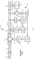
- FIG. 2 Shown in Fig. 2 is a UWB receiver 10' constructed in accordance with our invention.
- the signal received by antenna 12 is continuously conditioned by filter 14.
- the conditioned signal is then periodically sampled by an analog-to-digital converter ("ADC") 20 and provided as a continuous series of digital samples.
- ADC 20 is specially adapted to provide each digital sample in ternary form, i.e ., [-1, 0, +1].
- ADC 20 implements only positive/negative magnitude thresholds [T 0 ⁇ ⁇ ], thereby simplifying the circuit while simultaneously improving both the conversion time of the ADC 20 and, in general, the performance of the receiver.
- Such an implementation lends itself naturally to our trit-based scheme, wherein the three defined states indicate, for example, that:
- our trit-based ADC 20 can be readily adapted to operate either at a higher sample rate (improved performance but with more power) or at an equivalent sample rate (substantially equivalent performance but with less complexity, thereby reducing both circuit size and power consumption).
- receiver 10' initially operates in an acquisition mode, during which the components are configured to detect an incoming UWB signal transmitted by a remote UWB transmitter (not shown), and to achieve synchronism with that transmission, a process referred to as acquisition. Having achieved acquisition, receiver 10' transitions into a data mode, during which the components are configured to recover data contained within each transmitted packet, a process referred to as demodulation or data recovery.
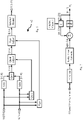
- FIG. 3 Shown in Fig. 3 are the components of our receiver 10' that perform carrier and timing recovery when the receiver 10' is operating in the acquisition mode.
- ADC 20 develops trit-valued samples of both the in-phase, Sr[5:0], and quadrature, Si[5:0], components of the received signals.
- these samples are passed to the correlator 24, where they are correlated against the predefined preamble code. If a valid preamble is present, the output of the correlator 24 comprises a noisy estimate of the channel impulse response (" CIR "). This noisy CIR estimate is passed, without carrier and timing recovery, to accumulator 26.
- CIR channel impulse response
- the acquisition control logic (described in our Related References) can determine if there is a valid preamble present.
- the carrier recovery logic is activated to correct carrier error in the received data.
- Logic 46 computes an instantaneous phase error estimate of the received UWB signal by performing an inverse tangent operation on the in-phase, i.e., real, and quadrature, i.e ., imaginary , components of the signal phasor.
- a carrier loop filter 48 uses this estimate to compute a correction angle to be applied to the current input to the accumulator 26. This correction angle is developed as a carrier recovery phase signal (7-bits unsigned) wherein the output range is 0.0 to almost 2.0, and where the value 2.0 is equivalent to one revolution.
- a look-up-table (“LUI ") 50 converts the correction angle to a corresponding pair of cosine (5-bits, including a sign bit) and sine (5-bits, including a sign bit) values. Using these sine and cosine values, a rotator 52 rotates the correlated samples by implementing a complex multiplication for each sample, followed by rounding to return the output real and imaginary samples to 7-bit signed values. The rotated correlated samples are then resampled by resample 54 for use by the accumulator 26.
- a detected preamble is not valid. Accordingly, our accumulator 26 spends some time assessing the quality of the incoming signal. If the quality is found to be poor, the preamble is rejected and accumulator 26 resumes searching for a preamble. If the quality is found to be sufficiently high, the next task is to search for a start-of-frame-delimiter (" SFD ”) by comparing the incoming correlator samples against the accumulated CIR estimate. This is performed for each symbol, and the result quantised to a 2-bit signed value. This 2-bit signed value should be +1 throughout the preamble, but then, once the SFD pattern is received, it should follow the pattern of the SFD.
- SFD start-of-frame-delimiter
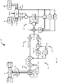
- Fig. 4 Shown in Fig. 4 are the components of our receiver 10' that perform carrier and timing recovery when the receiver 10' is operating in the data mode. No later than the end of the acquisition mode, the CIR estimate developed by accumulator 26 is loaded into the channel-matched-filter (" CMF ") 36. Once receiver 10' switches to data mode, the ADC 20 samples are passed to the CMF 36, which gathers the energy of the received UWB pulses together, thereby compensating for the smearing effect of the multi-path channel. The resulting output pulses are passed through the timing and carrier recovery loops to compensate for any offset, and then into despreader 40.
- CMF channel-matched-filter
- despreader 40 applies the same pseudo-random noise (“PN ”) spreading sequence used in the transmitter (not shown) to generate the burst, and integrates over the burst.
- PN pseudo-random noise
- despreader 40 does not know if a logic_1 or a logic_0 is being transmitted, it despreads at both possible locations to produce two estimates. These two estimates provide the soft input to the Viterbi decoder 42, which produces a maximum likelihood estimate of the bit sequence.
- the first section of the packet to be demodulated is the PHY header (" PHP ") , which contains information about the data rate and the number of octets transmitted. As is known, this is protected by a single-error-correct-double-error detect (“ SECDED ”) code.
- the relevant information is extracted to allow the demodulation, i.e., recovery, of the data payload.
- the remaining payload is then passed through the Viterbi decoder 42 to Reed-Solomon ("RS ") decoder 44 to correct any errors or report errors that cannot be corrected.
- RS Reed-Solomon
- the instantaneous phase error estimate is derived from the output of correlator 24 as follows:
- the complex instantaneous phase error estimate phasor simply comprises the outputs of despreader 40, comprising Sr[15:0] and Si[15:0].
- the instantaneous phase error estimate phasor is then converted to a corresponding angle by logic block 62.
- the complex error estimate phasor consists of two 17-bit signed numbers.
- the angle of the phasor is determined by dividing the imaginary component of the phasor, Si[15:0], by the real component, Sr[15:0]. Ideally the resulting quotient would then be passed to an inverse tangent function to compute the exact angle; however, for the purposes of our carrier recovery algorithm, we have determined that the quotient per se is a sufficient approximation to the angle.
- To simplify the division computation we first identify the sign and quadrant of the phasor, and then compute the absolute value of the real and imaginary parts.
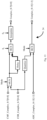
- carrier loop filter 48 can be seen in greater detail in Fig. 6 .
- the instantaneous phase error estimate is passed through a proportional gain arm 48a and an integral gain arm 48b.
- the gains, K p and K i are controlled by a gear-shifting algorithm to allow the loop to lock quickly, and then to rapidly tighten to a narrow bandwidth to minimise the impact of noise on the carrier recovery algorithm.
- the gear shifting is controlled by a counter ( e.g., see, Fig. 7 ) that counts the number of phase error estimates supplied to the loop, and selects a respective scaling factor. (The default gear shifting table is described below.)
- the filtered phase error estimate is accumulated in a carrier phase accumulator 48c to track the over-all phase error, and to adjust the instantaneous phase error to track frequency errors of up to +/- 40ppm.
- our approach is to scale the filtered phase error estimate and apply it to the accumulator more often than once per symbol.
- the filtered phase error will be scaled down by a factor of 2 and accumulated twice ( i . e ., every 64 clock cycles) during the phase update interval. (See, e.g., Fig. 8 .) This means that instead of the phase adjustment being applied in a single lump at the end of the interval, it will be distributed over the course of the symbol, thereby allowing the despread data towards the end of the interval to have a more accurate phase correction.
- the filtered phase error will be scaled down by a factor of 8 and accumulated 8 times ( i . e ., every 16 clock cycles) during the phase update interval.
- the filtered phase error estimate will be scaled down by a factor of 64 and accumulated 64 times ( i . e ., every 16 clock cycles) during the phase update interval.
- the despreader 40 will control when the phase rotation is applied, so that the phase rotation is updated just before it is needed for demodulation of a burst.
- a register-based field programmable gear shifting mechanism Ten gears may be configured; one is reserved for demodulation mode, allowing nine acquisition gears. Each gear is assigned: a count at which it is activated; a K p value; and a K i value. Writing a value of logic_0 as the count for a gear other than the first gear terminates the gear shifting table; whilst still switching to the demodulation gear when the acquisition phase is over. Note that two sets of demodulation coefficients must be specified, one for the 110Kbps data rate case, and one for the 850K and 6.81Mbps cases.
- Table 2 Carrier Recovery Loop Gear Shifting Table Register Count K i K p CR0 0 0x8: 3 ⁇ 2 -6 0x7: 2 -3 CR1 12 0x7: 3 ⁇ 2 -7 0x7: 2 -3 CR2 20 0x6: 3 ⁇ 2 -8 0x6: 2 -4 CR3 32 0x6: 3 ⁇ 2 -8 0x6: 2 -4 CR4 40 0x5: 3 ⁇ 2 -9 0x5: 2 -5 CR5 64 0x4: 3 ⁇ 2 -10 0x5: 2 -5 CR6 128 0x3: 3 ⁇ 2 -11 0x4: 2 -6 CR7 192 0x2: 3 ⁇ 2 -12 0x4: 2 -6 CR8 256 0x1: 3 ⁇ 2 -13 0x3: 2 -7 CR9
- the carrier recovery loop may fail to lock correctly. This will result in a preamble rejection in the accumulator 26 (if this mode is enabled), effectively giving the carrier recovery loop another shot.
- the timing recovery loop can still fail to lock, however, and it does not get another chance since by the time this has an effect the preamble will likely be confirmed.
- LUT 50 updates the SIN (5-bits signed) and COS (5-bits signed) values under the control of accumulator 26 during acquisition mode and by despreader 40 during data mode. This is in order to prevent phase changes being applied at times when the data is important to the algorithm in question, so it must be applied outside of the impulse response during acquisition, and outside of a burst position during demodulation.
- Rotator 52 takes the SIN and COS values from LUT 50 and applies them to the incoming data vectors. This rotation is applied to the correlator 24 outputs during acquisition, and to the CMF 36 outputs during data demodulation.
- the first stage, T0 selects between the registered outputs of correlator 24 and CMF 36 depending on the mode.
- the second stage, T1 performs the 4 multiplications that are required for a full complex multiplication, these multiplication results are then registered.
- the third stage, T2 sums the real components and the imaginary components of the complex multiplication, applies rounding to return the rotated samples to a precision of 7-bits (signed) and registers them for the output. Therefore the total latency of the rotator 52 is four clock cycles, C0-C3.
- Timing estimation is based on an early-late gating algorithm. As illustrated in Fig. 3 and Fig. 4 , the source of data for this algorithm is dependent upon the phase of reception: during acquisition mode, the necessary timing information is derived from the output of CMF 36; and, during data mode, the despreader 40 provides the necessary timing infonnation. In both cases the information is used to generate an instantaneous timing estimate. This estimate is conditioned and passed into a timing loop filter 64 typical of a second order loop. The timing loop filter 64 output provides sample-level timing adjustment information to the resampler 54 during acquisition mode, and clock cycle level adjustments to the accumulator 26 and despreader 40 during data mode.
- the timing estimate is derived from early/on-time/late samples from the output of the CMF 36.
- the accumulator 26 will start writing CIR coefficients to the CMF 36.
- the output of the correlator 24 provides an instantaneous noisy estimate of the CIR.
- the timing offset error accumulates in the accumulator 26, the position of this estimate within the symbol will slowly vary.
- Quantizing the correlator 24 output and feeding it into the CMF 36 result in a correlation peak at the output of the CMF 36 corresponding to the position of the noisy impulse response estimate in the correlator 24 output symbol.
- the functions of quantisation of the correlator 24 output and routing to CMF 36 are performed by resampler 54.
- the accumulator 26 provides a timing flag to indicate when the correlation peak is expected at the output of the CMF 36. This flag is based on the latency of the accumulator 26 and CMF 36 relative to the estimated impulse response location. Initially, this will be very accurate as the timing phase error will be negligible, but, as the phase error accumulates, the peak will move, thus providing the desired timing information.
- the correlation peak is ideally the on-time sample, with the early and late samples being the one immediately preceding and following the on-time sample respectively. These three samples are passed to a phase detector 66 (see, Fig. 3 ) that computes an instantaneous timing phase error for the timing loop filter 64.
- the despreader 40 provides dedicated early and late outputs in addition to the normal on-time output used as part of the demodulation process. These outputs are provided for both possible burst positions (depending on if the data is a logic_0 or a logic_1); thus, an early instantaneous decision is needed in order to identify which of the two sets of early/on-time/late samples to use in computing the instantaneous timing phase error estimate. Once this decision is made, the computation is performed and the error passed to the the timing loop filter 64.
- the phase error estimation is based on the previously described early/on-time/late samples.
- a difference computation is performed by computational block 68.
- the difference between the early and late values is computed and checked against the on-time (on-time should be greater). If the on-time value is negative or zero (after conditioning), then the data is unreliable and the phase estimate zeroed.
- the difference is divided by twice the peak and the result checked to be less than 0.75 (otherwise it is considered unreliable) and passed out as the instantaneous timing error estimate in the format S[-1:-4]. This instantaneous timing error estimate is then passed on to the timing loop filter 64.
- timing loop filter 64 comprises a proportional gain arm 64a and an integral gain arm 64b.
- the gains, Kp and Ki are controlled by a gear-shifting algorithm to allow the loop to lock quickly and then rapidly to tighten to a narrow bandwidth to minimise the impact of noise on the timing recovery algorithm.
- the gear shifting is controlled by a counter ( e.g., see, Fig.
- Timing loop filter accumulator 64c accumulates the lower noise estimate of the timing phase error to track the timing phase error and adjust the sampling phase error between 0 and +15.875 samples.
- Timing loop filter 64 also develops phase_increment ("Inc") and phase_decrement ("Dec") signals that are used to adjust the timing in units of 16 samples because they either drop or add a clock cycle delay in the accumulator 26 (during acquisition) or despreader 40 (during demodulation). Therefore, if an adjustment of -2.5 samples is required, then phase_inc is used to introduce an offset of -16 samples, while the phase error driving resampler 40 will apply a correction of +13.5 samples, giving the overall required phase adjustment of -2.5 samples.
- Inc phase_increment
- Dec phase_decrement
- an adjustment of +19.125 samples may be achieved by applying a +16 sample adjustment with the phase_dec signal, followed by an additional +3.125 sample correction in the resampler 54.
- a suitable embodiment of resample 54 is illustrated in Fig. 13 .
- the carrier recovery loop needs to lock quickly in order to successfully receive the signal, whereas the timing recovery loop can take longer. As a result, if the carrier recovery loop fails to lock soon after the preamble is found, then the preamble will be rejected, allowing the carrier recovery loop another chance to lock. The timing recovery loop, however, does not get a second chance, so, to improve the chances of lock, the timing recovery loop can be seeded with an estimate based on the carrier loop integrator.
- seeding is enabled via the use of a control signal: if the state of this signal is, e.g., logic_0, then timing seeding does not take place and the gearing table (see, below) must be set up to allow for this (initially wide bandwidth to allow acquisition, then narrowing as the lock improves); but, if the state of this signal is, e.g., logic_1, then timing seeding is enabled and the loop is assumed close to lock from the outset, and a more aggressive gearing table can be used. In our preferred embodiment, seeding is enabled by default.
- a register-based field programmable gear shifting mechanism Ten gears may be configured; one is reserved for demodulation mode, allowing nine acquisition gears. Each gear is assigned: a count at which it is activated; a K p value; and a K i value. Writing a value of logic_0 as the count for a gear other than the first gear terminates the gear shifting table; whilst still switching to the demodulation gear when the acquisition phase is over. Note that two sets of demodulation coefficients must be specified, one for the 110Kbps data rate case, and one for the 850K and 6.81Mbps cases.
- the several methods of our invention as disclosed herein in the context of special purpose receiver apparatus may be embodied in computer readable code on a suitable computer readable medium such that when a general or special purpose computer processor executes the computer readable code, the processor executes the respective method.
Landscapes
- Engineering & Computer Science (AREA)
- Computer Networks & Wireless Communication (AREA)
- Signal Processing (AREA)
- Digital Transmission Methods That Use Modulated Carrier Waves (AREA)
Claims (12)
- Verfahren zur Verwendung in einem Ultrabreitband-, UWB-, Kommunikationssystem, in dem ein moduliertes Trägersignal über einen Übertragungskanal mit einer Impulsantwort übertragen wird, wobei das Verfahren die folgenden Schritte umfasst: 1.1. Entwickeln einer Mehrzahl von komplexen Schätzungen der Impulsantwort durch:1.1.1. Empfangen des modulierten Trägersignals an einer Antenne (12);1.1.2. Aufbereiten des empfangenen Signals unter Verwendung eines Filters (14);1.1.3. periodisches Abtasten des aufbereiteten Signals unter Verwendung eines Analog-Digital-Umsetzers (20), um eine Reihe von digitalen Abtastwerten bereitzustellen;1.1.4. Korrelieren der Abtastwerte aus dem Analog-Digital-Umsetzer (20) mit einem vordefinierten Präambelcode unter Verwendung eines Korrelators (24), um die Mehrzahl von komplexen Schätzungen der Impulsantwort bereitzustellen;1.2. Entwickeln einer ersten akkumulierten Schätzung der Impulsantwort als eine Funktion eines ersten Satzes der komplexen Schätzungen der Impulsantwort, der ausgewählte erste und zweite der Mehrzahl von komplexen Schätzungen der Impulsantwort umfasst;1.3. Entwickeln eines komplexen Produktvektors durch Korrelieren der ersten akkumulierten Schätzung der Impulsantwort, die in Schritt 1.2 oder Schritt 1.5 entwickelt wurde, mit einer dritten komplexen Schätzung der von dem Korrelator (24) empfangenen Impulsantwort;1.4. Entwickeln eines Trägerfehlerwinkels als eine Funktion des genannten komplexen Produktvektors;1.5. Akkumulieren der dritten komplexen Schätzung der Impulsantwort mit der ersten akkumulierten Schätzung der Impulsantwort, um eine aktualisierte erste akkumulierte Schätzung der Impulsantwort zu entwickeln; und1.6. Wiederholen der Schritte 1.3 bis 1.5, wobei Schritt1.3 ferner gekennzeichnet ist durch:
1.3. Entwickeln eines komplexen Produktvektors durch Durchführen einer ausgewählten von:1.3.1. Entwickeln einer ersten komplexen Konjugierten einer ausgewählten dritten der Mehrzahl von komplexen Schätzungen der Impulsantwort; und1.3.2. Entwickeln des komplexen Produktvektors durch Multiplizieren der ersten akkumulierten Schätzung der Impulsantwort mit der ersten komplex Konjugierten;
und:1.3.3. Entwickeln einer zweiten komplexen Konjugierten der ersten akkumulierten Schätzung der Impulsantwort; und1.3.4. Entwickeln des komplexen Produktvektors durch Multiplizieren der dritten komplexen Schätzung der Impulsantwort mit der zweiten komplex Konjugierten. - Verfahren nach Anspruch 1, wobei Schritt 1.4 das Entwickeln eines Trägerfehlerwinkels durch Summieren der Elemente des komplexen Produktvektors, um eine komplexe Summe zu bestimmen, und Berechnen des Winkels der komplexen Summe umfasst.
- Verfahren nach Anspruch 1 oder Anspruch 2, wobei der Schritt 1.4 ferner definiert ist als umfassend die folgenden Schritte:1.4.1. Entwickeln eines Trägerfehlerwinkels als Funktion des Produktvektors;1.4.2. Filtern des Trägerfehlerwinkels als Funktion einer ausgewählten Trägerschleifenfilter-Proportionalverstärkung und einer ausgewählten Trägerschleifenfilter-Integralverstärkung, um einen gefilterten Trägerfehlerwinkel zu entwickeln; und1.4.3. Rotieren der dritten komplexen Schätzung der Impulsantwort als Funktion des gefilterten Trägerfehlerwinkels.
- Verfahren nach Anspruch 3, wobei in Schritt 1.4.2 die Trägerschleifenfilter-Proportional- und Integralverstärkungen aus einer Mehrzahl von vorbestimmten Verstärkungen als Funktion eines vorbestimmten Trägerschleifenfilter-Schaltalgorithmus ausgewählt werden.
- Verfahren zur Verwendung in einem Ultrabreitband-, UWB-, Kommunikationssystem, in dem ein moduliertes Trägersignal über einen Übertragungskanal mit einer Impulsantwort übertragen wird, wobei das Verfahren umfasst:Durchführen der Trägerwiederherstellung durch Durchführen der Schritte des Verfahrens nach einem der Ansprüche 1 bis 4; undDurchführen der zeitlichen Wiederherstellung durch:5.1. Entwickeln einer Mehrzahl von komplexen Schätzungen der Impulsantwort;5.2. Entwickeln einer akkumulierten Schätzung der Impulsantwort als Funktion eines Satzes von komplexen Schätzungen der Impulsantwort;5.3. Korrelieren eines weiteren Satzes der komplexen Schätzungen der Impulsantwort mit der akkumulierten Schätzung der Impulsantwort;5.4. Entwickeln einer geschätzten Spitze der Korrelation, wobei die Spitze einer ausgewählten Ein-Zeit-Schätzung in dem weiteren Satz von komplexen Schätzungen der Impulsantwort entspricht;5.5. Entwickeln eines zeitlichen Phasenfehlers als Funktion der Ein-Zeit-Schätzung, einer ausgewählten frühen Schätzung der Impulsantwort in dem weiteren Satz komplexer Schätzungen der Impulsantwort, die der Ein-Zeit-Schätzung vorangehen, und einer ausgewählten späten Schätzung der Impulsantwort in dem weiteren Satz komplexer Schätzungen der Impulsantwort, die der Ein-Zeit-Schätzung folgt.
- Verfahren nach Anspruch 5, wobei das Durchführen der zeitlichen Wiederherstellung ferner umfasst:
5.6. erneutes Abtasten der komplexen Schätzungen der Impulsantwort durch den Zeitphasenfehler, der dem weiteren Satz von komplexen Schätzungen der Impulsantwort folgt,
bevorzugt, wobei das Durchführen der zeitlichen Wiederherstellung ferner umfasst:
5.7. erneutes Abtasten des gefilterten Trägersignals durch den Zeitphasenfehler. - Verfahren nach einem der Ansprüche 5 oder 6, wobei der Schritt 5.5 ferner definiert ist als die folgenden Schritte umfassend:5.5.1. Entwickeln eines Zeitphasenfehlers als Funktion der Ein-Zeit-Schätzung, einer ausgewählten frühen Schätzung in dem weiteren Satz komplexer Schätzungen der Impulsantwort, die der Ein-Zeit-Schätzung vorangeht, und einer ausgewählten späten Schätzung in dem weiteren Satz komplexer Schätzungen der Impulsantwort, die der Ein-Zeit-Schätzung folgt;5.5.2. Filtern des Zeitphasenfehlers als Funktion einer ausgewählten Zeitschleifenfilter-Proportionalverstärkung und einer ausgewählten Zeitschleifenfilter-Integralverstärkung, um einen gefilterten Zeitphasenfehler zu erhalten; und5.5.3. erneutes Abtasten des gefilterten Trägersignals als Funktion des gefilterten Zeitphasenfehlers.
- Verfahren nach Anspruch 7, wobei in Schritt 5.5.2 die Zeitschleifenfilter-Proportional- und - Integralverstärkungen aus einer Mehrzahl von vorbestimmten Verstärkungen als Funktion eines vorbestimmten Zeitschleifenfilter-Schaltalgorithmus ausgewählt werden.
- Verfahren nach einem der Ansprüche 5 bis 8, wobei die frühe Schätzung die komplexe Schätzung der Impulsantwort in dem weiteren Satz komplexer Schätzungen der Impulsantwort umfasst, der der Ein-Zeit-Schätzung unmittelbar vorangeht, und/oder wobei die späte Schätzung die komplexe Schätzung der Impulsantwort in dem weiteren Satz umfasst, der der Ein-Zeit-Schätzung unmittelbar folgt.
- Verfahren zur Verwendung in einem Ultrabreitband-, UWB-, Kommunikationssystem, in dem ein moduliertes Trägersignal über einen Übertragungskanal mit einer Impulsantwort übertragen wird, wobei das Verfahren umfasst:
in einem Träger-Erfassungsmodus des Betriebs, Durchführen der Schritte des Verfahrens nach einem der Ansprüche 5 bis 9. - Vorrichtung (10') zur Verwendung in einem Ultrabreitband-, UWB-, Kommunikationssystem, in dem ein moduliertes Trägersignal über einen Übertragungskanal übertragen wird, wobei die Vorrichtung dazu ausgelegt ist, das Verfahren nach einem der vorhergehenden Ansprüche durchzuführen.
- Nicht flüchtiges computerlesbares Medium, das ausführbare Anweisungen beinhaltet, die, wenn sie in einem Verarbeitungssystem ausgeführt werden, das Verarbeitungssystem veranlassen, ein Verfahren nach einem der Ansprüche 1 bis 10 durchzuführen.
Priority Applications (1)
| Application Number | Priority Date | Filing Date | Title |
|---|---|---|---|
| EP16175355.3A EP3116134B1 (de) | 2013-10-07 | 2013-10-07 | Empfänger zur verwendung in einem ultrabreitband-kommunikationssystem |
Applications Claiming Priority (1)
| Application Number | Priority Date | Filing Date | Title |
|---|---|---|---|
| PCT/EP2013/070851 WO2015051821A1 (en) | 2013-10-07 | 2013-10-07 | A receiver for use in an ultra-wideband communication system |
Related Child Applications (2)
| Application Number | Title | Priority Date | Filing Date |
|---|---|---|---|
| EP16175355.3A Division EP3116134B1 (de) | 2013-10-07 | 2013-10-07 | Empfänger zur verwendung in einem ultrabreitband-kommunikationssystem |
| EP16175355.3A Division-Into EP3116134B1 (de) | 2013-10-07 | 2013-10-07 | Empfänger zur verwendung in einem ultrabreitband-kommunikationssystem |
Publications (2)
| Publication Number | Publication Date |
|---|---|
| EP3055932A1 EP3055932A1 (de) | 2016-08-17 |
| EP3055932B1 true EP3055932B1 (de) | 2023-03-01 |
Family
ID=49328515
Family Applications (2)
| Application Number | Title | Priority Date | Filing Date |
|---|---|---|---|
| EP13774644.2A Active EP3055932B1 (de) | 2013-10-07 | 2013-10-07 | Empfänger für ein ultrabreitbandkommunikationssystem |
| EP16175355.3A Active EP3116134B1 (de) | 2013-10-07 | 2013-10-07 | Empfänger zur verwendung in einem ultrabreitband-kommunikationssystem |
Family Applications After (1)
| Application Number | Title | Priority Date | Filing Date |
|---|---|---|---|
| EP16175355.3A Active EP3116134B1 (de) | 2013-10-07 | 2013-10-07 | Empfänger zur verwendung in einem ultrabreitband-kommunikationssystem |
Country Status (2)
| Country | Link |
|---|---|
| EP (2) | EP3055932B1 (de) |
| WO (2) | WO2015051821A1 (de) |
Families Citing this family (8)
| Publication number | Priority date | Publication date | Assignee | Title |
|---|---|---|---|---|
| USRE48832E1 (en) | 2010-03-22 | 2021-11-23 | DecaWave, Ltd. | Measuring angle of incidence in an ultrawideband communication system |
| US10459063B2 (en) | 2016-02-16 | 2019-10-29 | Irobot Corporation | Ranging and angle of arrival antenna system for a mobile robot |
| CN107966676B (zh) * | 2017-08-04 | 2019-11-08 | 大连理工大学 | 复杂噪声环境下阵列天线角度和信源个数联合估计方法 |
| US10509116B2 (en) | 2018-04-26 | 2019-12-17 | DecaWave, Ltd. | Method and apparatus for determining location using phase difference of arrival |
| US11422220B2 (en) | 2020-06-17 | 2022-08-23 | Qorvo Us, Inc. | Method and apparatus for determining the angle of departure |
| US11128342B2 (en) | 2019-02-02 | 2021-09-21 | DecaWave, Ltd. | Method and apparatus for determining the angle of departure |
| US20220397629A1 (en) | 2019-02-02 | 2022-12-15 | DecaWave, Ltd. | Method and apparatus for determining the angle of departure |
| CN118266133A (zh) * | 2021-10-14 | 2024-06-28 | 斯帕克微系统国际股份有限公司 | 超宽带无线电装置和方法 |
Citations (4)
| Publication number | Priority date | Publication date | Assignee | Title |
|---|---|---|---|---|
| US20040101068A1 (en) * | 2002-11-25 | 2004-05-27 | Tzu-Pai Wang | Digital receiver capable of processing modulated signals at various data rates |
| US20070140323A1 (en) * | 2005-12-20 | 2007-06-21 | Shimman Patel | Coarse bin frequency synchronization in a communication system |
| US20100260233A1 (en) * | 2009-04-14 | 2010-10-14 | Qualcomm Incorporated | Phase tracking in frequency domain in a wireless communication system |
| US20130163638A1 (en) * | 2010-03-22 | 2013-06-27 | Decawave Limited | Receiver For Use In An Ultra-Wideband Communication System |
Family Cites Families (9)
| Publication number | Priority date | Publication date | Assignee | Title |
|---|---|---|---|---|
| US20040151269A1 (en) * | 2003-01-21 | 2004-08-05 | Jaiganesh Balakrishnan | Receiver sampling in an ultra-wideband communications system |
| US7349461B2 (en) | 2003-02-13 | 2008-03-25 | Qualcomm Incorporated | Efficient back-end channel matched filter (CMF) |
| US20070085715A1 (en) | 2005-07-19 | 2007-04-19 | Michael McLauglhlin | Method and apparatus for generating codewords and sets of codewords which are useful for both coherent and non-coherent channel sounding and ranging and also have good auto correlation, cross correlation and spectral properties |
| US8466836B2 (en) * | 2005-08-31 | 2013-06-18 | CSR Technology Holdings Inc. | Fast fourier transform with down sampling based navigational satellite signal tracking |
| US7636397B2 (en) | 2005-09-07 | 2009-12-22 | Mclaughlin Michael | Method and apparatus for transmitting and receiving convolutionally coded data for use with combined binary phase shift keying (BPSK) modulation and pulse position modulation (PPM) |
| US7787544B2 (en) | 2006-07-13 | 2010-08-31 | Delaware Limited | Method and apparatus for generating codewords |
| US20080232514A1 (en) * | 2007-03-22 | 2008-09-25 | Skytraq Technology Inc. | GPS signal acquisition circuit |
| KR100922857B1 (ko) * | 2007-12-10 | 2009-10-22 | 한국전자통신연구원 | 초광대역 무선시스템의 수신장치 및 그 수신방법 |
| US8677224B2 (en) | 2010-04-21 | 2014-03-18 | Decawave Ltd. | Convolutional code for use in a communication system |
-
2013
- 2013-10-07 EP EP13774644.2A patent/EP3055932B1/de active Active
- 2013-10-07 EP EP16175355.3A patent/EP3116134B1/de active Active
- 2013-10-07 WO PCT/EP2013/070851 patent/WO2015051821A1/en not_active Ceased
-
2014
- 2014-09-04 WO PCT/GB2014/052677 patent/WO2015052486A1/en not_active Ceased
Patent Citations (4)
| Publication number | Priority date | Publication date | Assignee | Title |
|---|---|---|---|---|
| US20040101068A1 (en) * | 2002-11-25 | 2004-05-27 | Tzu-Pai Wang | Digital receiver capable of processing modulated signals at various data rates |
| US20070140323A1 (en) * | 2005-12-20 | 2007-06-21 | Shimman Patel | Coarse bin frequency synchronization in a communication system |
| US20100260233A1 (en) * | 2009-04-14 | 2010-10-14 | Qualcomm Incorporated | Phase tracking in frequency domain in a wireless communication system |
| US20130163638A1 (en) * | 2010-03-22 | 2013-06-27 | Decawave Limited | Receiver For Use In An Ultra-Wideband Communication System |
Also Published As
| Publication number | Publication date |
|---|---|
| WO2015052486A1 (en) | 2015-04-16 |
| EP3116134A1 (de) | 2017-01-11 |
| EP3116134B1 (de) | 2022-05-11 |
| WO2015051821A1 (en) | 2015-04-16 |
| EP3055932A1 (de) | 2016-08-17 |
Similar Documents
| Publication | Publication Date | Title |
|---|---|---|
| US10491266B2 (en) | Timing recovery for use in an ultra-wideband communication system | |
| EP3840236B1 (de) | Messung des einfallswinkels in einem ultrabreitband-kommunikationssystem | |
| US20180331718A1 (en) | Carrier recovery for use in an ultra-wideband communication system | |
| EP3055932B1 (de) | Empfänger für ein ultrabreitbandkommunikationssystem | |
| US10056993B2 (en) | Angle of arrival using reduced number of receivers | |
| US10177809B1 (en) | Receiver for use in an ultra-wideband communication system | |
| US9054790B2 (en) | Receiver for use in an ultra-wideband communication system | |
| US8760334B2 (en) | Receiver for use in an ultra-wideband communication system | |
| US20120069868A1 (en) | Receiver for use in an ultra-wideband communication system | |
| WO2009093892A1 (en) | Arrangement for determining a characteristic form of an input signal | |
| US10090879B2 (en) | Receiver for use in an ultra-wideband communication system | |
| EP3195487B1 (de) | Empfänger zur verwendung in einem ultrabreitband-kommunikationssystem | |
| EP1292077A2 (de) | Folgeschätzung für mit phasensprüngen modulierte Signale | |
| KR102269693B1 (ko) | 변조 신호의 주파수 및 타이밍 오프셋에 대한 추적 및 보상 시스템 및 방법 | |
| USRE48832E1 (en) | Measuring angle of incidence in an ultrawideband communication system | |
| CN101019389B (zh) | 信道响应估算的设备及其方法 | |
| WO2025237379A1 (zh) | 联合解映射和译码方法、装置、译码器、集成电路、器件和设备 | |
| US20120300821A1 (en) | Adaptive channel tracking using peak fade depth estimation over a slot | |
| US20040264606A1 (en) | Method and apparatus for demodulating block-code signals |
Legal Events
| Date | Code | Title | Description |
|---|---|---|---|
| PUAI | Public reference made under article 153(3) epc to a published international application that has entered the european phase |
Free format text: ORIGINAL CODE: 0009012 |
|
| 17P | Request for examination filed |
Effective date: 20160504 |
|
| AK | Designated contracting states |
Kind code of ref document: A1 Designated state(s): AL AT BE BG CH CY CZ DE DK EE ES FI FR GB GR HR HU IE IS IT LI LT LU LV MC MK MT NL NO PL PT RO RS SE SI SK SM TR |
|
| AX | Request for extension of the european patent |
Extension state: BA ME |
|
| RIN1 | Information on inventor provided before grant (corrected) |
Inventor name: MCELROY, CIARAN Inventor name: MCLAUGHLIN, MICHAEL Inventor name: NEIRYNCK, DRIES |
|
| DAX | Request for extension of the european patent (deleted) | ||
| STAA | Information on the status of an ep patent application or granted ep patent |
Free format text: STATUS: EXAMINATION IS IN PROGRESS |
|
| PUAG | Search results despatched under rule 164(2) epc together with communication from examining division |
Free format text: ORIGINAL CODE: 0009017 |
|
| 17Q | First examination report despatched |
Effective date: 20190311 |
|
| B565 | Issuance of search results under rule 164(2) epc |
Effective date: 20190311 |
|
| RIC1 | Information provided on ipc code assigned before grant |
Ipc: H04B 1/7163 20110101AFI20190306BHEP Ipc: H04B 1/7183 20110101ALI20190306BHEP |
|
| GRAP | Despatch of communication of intention to grant a patent |
Free format text: ORIGINAL CODE: EPIDOSNIGR1 |
|
| STAA | Information on the status of an ep patent application or granted ep patent |
Free format text: STATUS: GRANT OF PATENT IS INTENDED |
|
| INTG | Intention to grant announced |
Effective date: 20220921 |
|
| GRAS | Grant fee paid |
Free format text: ORIGINAL CODE: EPIDOSNIGR3 |
|
| GRAA | (expected) grant |
Free format text: ORIGINAL CODE: 0009210 |
|
| STAA | Information on the status of an ep patent application or granted ep patent |
Free format text: STATUS: THE PATENT HAS BEEN GRANTED |
|
| AK | Designated contracting states |
Kind code of ref document: B1 Designated state(s): AL AT BE BG CH CY CZ DE DK EE ES FI FR GB GR HR HU IE IS IT LI LT LU LV MC MK MT NL NO PL PT RO RS SE SI SK SM TR |
|
| REG | Reference to a national code |
Ref country code: GB Ref legal event code: FG4D |
|
| REG | Reference to a national code |
Ref country code: CH Ref legal event code: EP Ref country code: AT Ref legal event code: REF Ref document number: 1551718 Country of ref document: AT Kind code of ref document: T Effective date: 20230315 |
|
| REG | Reference to a national code |
Ref country code: DE Ref legal event code: R096 Ref document number: 602013083387 Country of ref document: DE |
|
| REG | Reference to a national code |
Ref country code: IE Ref legal event code: FG4D |
|
| P01 | Opt-out of the competence of the unified patent court (upc) registered |
Effective date: 20230515 |
|
| REG | Reference to a national code |
Ref country code: LT Ref legal event code: MG9D |
|
| REG | Reference to a national code |
Ref country code: NL Ref legal event code: MP Effective date: 20230301 |
|
| PG25 | Lapsed in a contracting state [announced via postgrant information from national office to epo] |
Ref country code: RS Free format text: LAPSE BECAUSE OF FAILURE TO SUBMIT A TRANSLATION OF THE DESCRIPTION OR TO PAY THE FEE WITHIN THE PRESCRIBED TIME-LIMIT Effective date: 20230301 Ref country code: NO Free format text: LAPSE BECAUSE OF FAILURE TO SUBMIT A TRANSLATION OF THE DESCRIPTION OR TO PAY THE FEE WITHIN THE PRESCRIBED TIME-LIMIT Effective date: 20230601 Ref country code: LV Free format text: LAPSE BECAUSE OF FAILURE TO SUBMIT A TRANSLATION OF THE DESCRIPTION OR TO PAY THE FEE WITHIN THE PRESCRIBED TIME-LIMIT Effective date: 20230301 Ref country code: LT Free format text: LAPSE BECAUSE OF FAILURE TO SUBMIT A TRANSLATION OF THE DESCRIPTION OR TO PAY THE FEE WITHIN THE PRESCRIBED TIME-LIMIT Effective date: 20230301 Ref country code: HR Free format text: LAPSE BECAUSE OF FAILURE TO SUBMIT A TRANSLATION OF THE DESCRIPTION OR TO PAY THE FEE WITHIN THE PRESCRIBED TIME-LIMIT Effective date: 20230301 Ref country code: ES Free format text: LAPSE BECAUSE OF FAILURE TO SUBMIT A TRANSLATION OF THE DESCRIPTION OR TO PAY THE FEE WITHIN THE PRESCRIBED TIME-LIMIT Effective date: 20230301 |
|
| REG | Reference to a national code |
Ref country code: AT Ref legal event code: MK05 Ref document number: 1551718 Country of ref document: AT Kind code of ref document: T Effective date: 20230301 |
|
| PG25 | Lapsed in a contracting state [announced via postgrant information from national office to epo] |
Ref country code: SE Free format text: LAPSE BECAUSE OF FAILURE TO SUBMIT A TRANSLATION OF THE DESCRIPTION OR TO PAY THE FEE WITHIN THE PRESCRIBED TIME-LIMIT Effective date: 20230301 Ref country code: PL Free format text: LAPSE BECAUSE OF FAILURE TO SUBMIT A TRANSLATION OF THE DESCRIPTION OR TO PAY THE FEE WITHIN THE PRESCRIBED TIME-LIMIT Effective date: 20230301 Ref country code: NL Free format text: LAPSE BECAUSE OF FAILURE TO SUBMIT A TRANSLATION OF THE DESCRIPTION OR TO PAY THE FEE WITHIN THE PRESCRIBED TIME-LIMIT Effective date: 20230301 Ref country code: GR Free format text: LAPSE BECAUSE OF FAILURE TO SUBMIT A TRANSLATION OF THE DESCRIPTION OR TO PAY THE FEE WITHIN THE PRESCRIBED TIME-LIMIT Effective date: 20230602 Ref country code: FI Free format text: LAPSE BECAUSE OF FAILURE TO SUBMIT A TRANSLATION OF THE DESCRIPTION OR TO PAY THE FEE WITHIN THE PRESCRIBED TIME-LIMIT Effective date: 20230301 |
|
| PG25 | Lapsed in a contracting state [announced via postgrant information from national office to epo] |
Ref country code: SM Free format text: LAPSE BECAUSE OF FAILURE TO SUBMIT A TRANSLATION OF THE DESCRIPTION OR TO PAY THE FEE WITHIN THE PRESCRIBED TIME-LIMIT Effective date: 20230301 Ref country code: RO Free format text: LAPSE BECAUSE OF FAILURE TO SUBMIT A TRANSLATION OF THE DESCRIPTION OR TO PAY THE FEE WITHIN THE PRESCRIBED TIME-LIMIT Effective date: 20230301 Ref country code: PT Free format text: LAPSE BECAUSE OF FAILURE TO SUBMIT A TRANSLATION OF THE DESCRIPTION OR TO PAY THE FEE WITHIN THE PRESCRIBED TIME-LIMIT Effective date: 20230703 Ref country code: EE Free format text: LAPSE BECAUSE OF FAILURE TO SUBMIT A TRANSLATION OF THE DESCRIPTION OR TO PAY THE FEE WITHIN THE PRESCRIBED TIME-LIMIT Effective date: 20230301 Ref country code: CZ Free format text: LAPSE BECAUSE OF FAILURE TO SUBMIT A TRANSLATION OF THE DESCRIPTION OR TO PAY THE FEE WITHIN THE PRESCRIBED TIME-LIMIT Effective date: 20230301 Ref country code: AT Free format text: LAPSE BECAUSE OF FAILURE TO SUBMIT A TRANSLATION OF THE DESCRIPTION OR TO PAY THE FEE WITHIN THE PRESCRIBED TIME-LIMIT Effective date: 20230301 |
|
| PG25 | Lapsed in a contracting state [announced via postgrant information from national office to epo] |
Ref country code: SK Free format text: LAPSE BECAUSE OF FAILURE TO SUBMIT A TRANSLATION OF THE DESCRIPTION OR TO PAY THE FEE WITHIN THE PRESCRIBED TIME-LIMIT Effective date: 20230301 Ref country code: IS Free format text: LAPSE BECAUSE OF FAILURE TO SUBMIT A TRANSLATION OF THE DESCRIPTION OR TO PAY THE FEE WITHIN THE PRESCRIBED TIME-LIMIT Effective date: 20230701 |
|
| REG | Reference to a national code |
Ref country code: DE Ref legal event code: R097 Ref document number: 602013083387 Country of ref document: DE |
|
| PLBE | No opposition filed within time limit |
Free format text: ORIGINAL CODE: 0009261 |
|
| STAA | Information on the status of an ep patent application or granted ep patent |
Free format text: STATUS: NO OPPOSITION FILED WITHIN TIME LIMIT |
|
| PG25 | Lapsed in a contracting state [announced via postgrant information from national office to epo] |
Ref country code: SI Free format text: LAPSE BECAUSE OF FAILURE TO SUBMIT A TRANSLATION OF THE DESCRIPTION OR TO PAY THE FEE WITHIN THE PRESCRIBED TIME-LIMIT Effective date: 20230301 Ref country code: DK Free format text: LAPSE BECAUSE OF FAILURE TO SUBMIT A TRANSLATION OF THE DESCRIPTION OR TO PAY THE FEE WITHIN THE PRESCRIBED TIME-LIMIT Effective date: 20230301 |
|
| 26N | No opposition filed |
Effective date: 20231204 |
|
| PG25 | Lapsed in a contracting state [announced via postgrant information from national office to epo] |
Ref country code: IT Free format text: LAPSE BECAUSE OF FAILURE TO SUBMIT A TRANSLATION OF THE DESCRIPTION OR TO PAY THE FEE WITHIN THE PRESCRIBED TIME-LIMIT Effective date: 20230301 Ref country code: MC Free format text: LAPSE BECAUSE OF FAILURE TO SUBMIT A TRANSLATION OF THE DESCRIPTION OR TO PAY THE FEE WITHIN THE PRESCRIBED TIME-LIMIT Effective date: 20230301 |
|
| REG | Reference to a national code |
Ref country code: CH Ref legal event code: PL |
|
| REG | Reference to a national code |
Ref country code: BE Ref legal event code: MM Effective date: 20231031 |
|
| PG25 | Lapsed in a contracting state [announced via postgrant information from national office to epo] |
Ref country code: LU Free format text: LAPSE BECAUSE OF NON-PAYMENT OF DUE FEES Effective date: 20231007 |
|
| PG25 | Lapsed in a contracting state [announced via postgrant information from national office to epo] |
Ref country code: LU Free format text: LAPSE BECAUSE OF NON-PAYMENT OF DUE FEES Effective date: 20231007 |
|
| PG25 | Lapsed in a contracting state [announced via postgrant information from national office to epo] |
Ref country code: CH Free format text: LAPSE BECAUSE OF NON-PAYMENT OF DUE FEES Effective date: 20231031 |
|
| PG25 | Lapsed in a contracting state [announced via postgrant information from national office to epo] |
Ref country code: CH Free format text: LAPSE BECAUSE OF NON-PAYMENT OF DUE FEES Effective date: 20231031 |
|
| PG25 | Lapsed in a contracting state [announced via postgrant information from national office to epo] |
Ref country code: BE Free format text: LAPSE BECAUSE OF NON-PAYMENT OF DUE FEES Effective date: 20231031 |
|
| PG25 | Lapsed in a contracting state [announced via postgrant information from national office to epo] |
Ref country code: IE Free format text: LAPSE BECAUSE OF NON-PAYMENT OF DUE FEES Effective date: 20231007 |
|
| PG25 | Lapsed in a contracting state [announced via postgrant information from national office to epo] |
Ref country code: IE Free format text: LAPSE BECAUSE OF NON-PAYMENT OF DUE FEES Effective date: 20231007 |
|
| PG25 | Lapsed in a contracting state [announced via postgrant information from national office to epo] |
Ref country code: BG Free format text: LAPSE BECAUSE OF FAILURE TO SUBMIT A TRANSLATION OF THE DESCRIPTION OR TO PAY THE FEE WITHIN THE PRESCRIBED TIME-LIMIT Effective date: 20230301 |
|
| PG25 | Lapsed in a contracting state [announced via postgrant information from national office to epo] |
Ref country code: BG Free format text: LAPSE BECAUSE OF FAILURE TO SUBMIT A TRANSLATION OF THE DESCRIPTION OR TO PAY THE FEE WITHIN THE PRESCRIBED TIME-LIMIT Effective date: 20230301 |
|
| PG25 | Lapsed in a contracting state [announced via postgrant information from national office to epo] |
Ref country code: CY Free format text: LAPSE BECAUSE OF FAILURE TO SUBMIT A TRANSLATION OF THE DESCRIPTION OR TO PAY THE FEE WITHIN THE PRESCRIBED TIME-LIMIT; INVALID AB INITIO Effective date: 20131007 |
|
| PG25 | Lapsed in a contracting state [announced via postgrant information from national office to epo] |
Ref country code: HU Free format text: LAPSE BECAUSE OF FAILURE TO SUBMIT A TRANSLATION OF THE DESCRIPTION OR TO PAY THE FEE WITHIN THE PRESCRIBED TIME-LIMIT; INVALID AB INITIO Effective date: 20131007 |
|
| PGFP | Annual fee paid to national office [announced via postgrant information from national office to epo] |
Ref country code: GB Payment date: 20250923 Year of fee payment: 13 |
|
| PGFP | Annual fee paid to national office [announced via postgrant information from national office to epo] |
Ref country code: FR Payment date: 20250924 Year of fee payment: 13 |
|
| PG25 | Lapsed in a contracting state [announced via postgrant information from national office to epo] |
Ref country code: TR Free format text: LAPSE BECAUSE OF FAILURE TO SUBMIT A TRANSLATION OF THE DESCRIPTION OR TO PAY THE FEE WITHIN THE PRESCRIBED TIME-LIMIT Effective date: 20230301 |
|
| PGFP | Annual fee paid to national office [announced via postgrant information from national office to epo] |
Ref country code: DE Payment date: 20250923 Year of fee payment: 13 |