EP3055935B1 - Contrôleur de communication et procédé de commande de longueur d'onde - Google Patents
Contrôleur de communication et procédé de commande de longueur d'onde Download PDFInfo
- Publication number
- EP3055935B1 EP3055935B1 EP13799694.8A EP13799694A EP3055935B1 EP 3055935 B1 EP3055935 B1 EP 3055935B1 EP 13799694 A EP13799694 A EP 13799694A EP 3055935 B1 EP3055935 B1 EP 3055935B1
- Authority
- EP
- European Patent Office
- Prior art keywords
- channel
- bit error
- error rate
- wavelength
- tuning
- Prior art date
- Legal status (The legal status is an assumption and is not a legal conclusion. Google has not performed a legal analysis and makes no representation as to the accuracy of the status listed.)
- Active
Links
Images


Classifications
-
- H—ELECTRICITY
- H04—ELECTRIC COMMUNICATION TECHNIQUE
- H04B—TRANSMISSION
- H04B10/00—Transmission systems employing electromagnetic waves other than radio-waves, e.g. infrared, visible or ultraviolet light, or employing corpuscular radiation, e.g. quantum communication
- H04B10/07—Arrangements for monitoring or testing transmission systems; Arrangements for fault measurement of transmission systems
- H04B10/075—Arrangements for monitoring or testing transmission systems; Arrangements for fault measurement of transmission systems using an in-service signal
- H04B10/079—Arrangements for monitoring or testing transmission systems; Arrangements for fault measurement of transmission systems using an in-service signal using measurements of the data signal
- H04B10/0795—Performance monitoring; Measurement of transmission parameters
- H04B10/07953—Monitoring or measuring OSNR, BER or Q
-
- H—ELECTRICITY
- H04—ELECTRIC COMMUNICATION TECHNIQUE
- H04B—TRANSMISSION
- H04B10/00—Transmission systems employing electromagnetic waves other than radio-waves, e.g. infrared, visible or ultraviolet light, or employing corpuscular radiation, e.g. quantum communication
- H04B10/07—Arrangements for monitoring or testing transmission systems; Arrangements for fault measurement of transmission systems
- H04B10/075—Arrangements for monitoring or testing transmission systems; Arrangements for fault measurement of transmission systems using an in-service signal
- H04B10/079—Arrangements for monitoring or testing transmission systems; Arrangements for fault measurement of transmission systems using an in-service signal using measurements of the data signal
- H04B10/0795—Performance monitoring; Measurement of transmission parameters
- H04B10/07957—Monitoring or measuring wavelength
-
- H—ELECTRICITY
- H04—ELECTRIC COMMUNICATION TECHNIQUE
- H04B—TRANSMISSION
- H04B10/00—Transmission systems employing electromagnetic waves other than radio-waves, e.g. infrared, visible or ultraviolet light, or employing corpuscular radiation, e.g. quantum communication
- H04B10/25—Arrangements specific to fibre transmission
- H04B10/2507—Arrangements specific to fibre transmission for the reduction or elimination of distortion or dispersion
-
- H—ELECTRICITY
- H04—ELECTRIC COMMUNICATION TECHNIQUE
- H04B—TRANSMISSION
- H04B10/00—Transmission systems employing electromagnetic waves other than radio-waves, e.g. infrared, visible or ultraviolet light, or employing corpuscular radiation, e.g. quantum communication
- H04B10/25—Arrangements specific to fibre transmission
- H04B10/2589—Bidirectional transmission
-
- H—ELECTRICITY
- H04—ELECTRIC COMMUNICATION TECHNIQUE
- H04B—TRANSMISSION
- H04B10/00—Transmission systems employing electromagnetic waves other than radio-waves, e.g. infrared, visible or ultraviolet light, or employing corpuscular radiation, e.g. quantum communication
- H04B10/50—Transmitters
- H04B10/501—Structural aspects
- H04B10/506—Multiwavelength transmitters
-
- H—ELECTRICITY
- H04—ELECTRIC COMMUNICATION TECHNIQUE
- H04B—TRANSMISSION
- H04B10/00—Transmission systems employing electromagnetic waves other than radio-waves, e.g. infrared, visible or ultraviolet light, or employing corpuscular radiation, e.g. quantum communication
- H04B10/50—Transmitters
- H04B10/572—Wavelength control
Definitions
- Embodiments herein generally relate to a communications controller, a corresponding method therein and a computer-readable medium for managing the communications controller. More particularly the embodiments herein relate to wavelength control of a first and second channel.
- the first and second channels are bidirectional and adjacent to one another in a single fiber in a Dense Wavelength Division Multiplexing (DWDM) based system.
- DWDM Dense Wavelength Division Multiplexing
- ROADM Reconfigurable Optical Add/Drop Multiplexers
- One such context relates to an aggregation network that efficiently transports the traffic of multiple services in a converged fashion. Rather than employing multiple different networks in parallel for transporting these different services (e.g., mobile, business, and residential services), a converged network transports those services together using the same network.
- a transport network that optically converges different services by transporting those services on different wavelengths would be advantageous, for a variety of reasons, but has heretofore been precluded in aggregation networks close to end-users by the high cost of the necessary hardware components (e.g., ROADMs).
- Some systems employ dense WDM at 25 GHz channel spacing, while most commercial systems for optical transport run over two unidirectional fibers. Also for access systems (e.g. passive optical networks), which typically use bidirectional fibers, so-called Ultra DWDM (UDWDM) has been proposed, with down to 3 GHz channel spacing.
- UDWDM Ultra DWDM
- Such UDWDM systems typically run over power split optical networks without networking (wavelength switching) of the individual wavelengths.
- very dense WDM the stability of the wavelengths is critical since overlapping channels interfere with each other causing bit errors.
- one solution is to create the very dense channels using a broadband modulator, thus not relying on the stability of individual lasers. In case the individual channels come from different ports or even different equipment, wavelength control of the individual lasers are required. This is typically done using combinations of temperature control and a wavelength reference, such as an etalon.
- Wavelength control using etalons may offer stability in the order of +/- 1.5 GHz, which may not be enough to assure satisfactory performance (e.g., Bit Error Rate (BER)) for the WDM, for example, with a channel spacing of 25 GHz.
- BER Bit Error Rate
- absolute frequency stability as required by a local method comes at increasing cost as requirements become tighter.
- Current systems rely on various methods to solve the above mentioned problems. Examples of such current methods are centralized control with a wavelength reference, and local control using the Rayleigh backscatter of the transmitted signal. Centralized control methods suffer from high cost and slow response times. Local control based methods suffer from poor stability.
- methods based on measuring optical power levels does not take into account cross-talks resulting from counter-propagating channels drifting close to each other.
- a DWDM wavelength control method according to the state of the art is known from USA-2010/239260 .
- At least one example object of the example embodiments presented herein is how to improve WDM systems. Accordingly, some of the example embodiments presented herein optimize the center wavelengths of two counter-propagating channels by measuring the BER at the two sides of the link and using a series of operations or tuning to control the wavelength tuning at both sides of the wavelength channel.
- the tuning solves the fundamentally difficult problem of having two measurement parameters to observe at least five causes of increased BER (e.g., laser drift at the two sides, filter drift, filter narrowing, and all other channel degradation effects not caused by wavelength drift) and to counter this by two control parameters (laser tuning at both sides).
- BER e.g., laser drift at the two sides, filter drift, filter narrowing, and all other channel degradation effects not caused by wavelength drift
- some of the example embodiments are directed towards a method, in a communications controller, for wavelength control of a first and second channel.
- the first and second channels are bidirectional and adjacent to one another in a single fiber in a DWDM based system.
- the method comprises receiving, from a receiver of the first channel, a current bit error rate of the first channel.
- the method also comprises receiving, from a receiver of the second channel, a current bit error rate of the second channel.
- the method further comprises comparing the current bit error rate of the first channel with a previous bit error rate of the first channel.
- the previous bit error rate of the first channel is determined at an earlier time as the current bit error rate of the first channel.
- the method further comprises comparing the current bit error rate of the second channel with a previous bit error rate of the second channel.
- the previous bit error rate of the second channel is determined at an earlier time as the current bit error rate of the second channel.
- the method further comprises identifying if the comparing described above is equivalent to one of three predetermined profiles.
- the predetermined profiles are:
- the method also comprises sending, to transmitter(s) of at least one of the first and second channel, a set of wavelength tuning instructions to tune a center wavelength of at least one of the first and second channel based on the identified predetermined profile, wherein each of the three predetermined profiles comprises a respective set of wavelength tuning instructions.
- Some of the example embodiments are directed towards a communications controller for wavelength control of a first and second channel.
- the first and second channels are bidirectional and adjacent to one another in a single fiber in a DWDM based system.
- the communications controller comprises control channel circuitry configured to receive, from a receiver of the first channel, a current bit error rate of the first channel.
- the control channel circuitry is further configured to receive, from a receiver of the second channel, a current bit error rate of the second channel.
- the communications controller further comprises processing circuitry configured to compare the current bit error rate of the first channel with a previous bit error rate of the first channel.
- the previous bit error rate of the first channel is determined at an earlier time as the current bit error rate of the first channel.
- the processing circuitry is further configured to compare the current bit error rate of the second channel with a previous bit error rate of the second channel.
- the previous bit error rate of the second channel is determined at an earlier time as the current bit error rate of the second channel.
- the processing circuitry is further configured to identify if the above mentioned comparisons are equivalent to one of three predetermined profiles.
- the predetermined profiles are:
- the control channel circuitry is further configured to send, to transmitter(s) of at least one of the first and second channel, a set of wavelength tuning instructions to tune a center wavelength of at least one of the first and second channel based on the identified predetermined profile, wherein each of the three predetermined profiles comprises a respective set of wavelength tuning instructions.
- Some of the example embodiments are directed towards a computer-readable medium having computer-executable instructions for managing a communications controller for wavelength control of a first and second channel.
- the first and second channels are bidirectional and adjacent to one another in a single fiber in a DWDM based system.
- the instructions comprise steps corresponding to the above described method.
- the example embodiments comprise at least the following example advantages.
- the example embodiments optimize the center wavelengths of the two counter-propagating channels by measuring the BER at the both sides of the link and using a series of tuning adjustments to control the wavelength tuning at both sides.
- the example embodiments find optimal tuning equal to the size of the fine tuning steps.
- a high capacity and performance may be achieved without high cost for wavelength control of DWDM transmitters.
- Figure 1 illustrates various examples of single fiber communications.
- a single bidirectional fiber with channel spacing of 100 GHz wavelength is provided.
- each upstream and downstream signal utilizes one 100 GHz slot. Therefore, 24 channels may be supported (assuming a C-band based system with 48 channels).
- signal interference is not a serious issue in such a system because there is sufficient channel spacing between upstream and downstream communications.
- example 1 only allows for the use of 24 channels. With the use of smaller channel spacing, a greater amount of channels may be utilized allowing for a more efficient use of system resources.
- Example 2 of Figure 1 illustrates a unidirectional 50 GHz channel spacing which supports 48 channels over one fiber.
- Example 2 of Figure 1 illustrates a unidirectional 50 GHz channel spacing which supports 48 channels over one fiber.
- Example 3 of Figure 1 illustrates a 50 GHz bidirectional channel supporting 96 channels. As compared to example 2, the number of available channels has doubled with the use of bidirectional communications. Example 3 features 25 GHz wavelength settings which may be provided with 50 GHz lasers with the possibility of an approximately 10 GHz offset. The 25 GHz wavelength and 10 GHz offset is available on the market, but not for pluggable modules.
- Example 4 illustrates a similar system to that of example 3, however example 4 features a channel spacing of 25 GHz with a 5-10 GHz offset.
- Example 4 illustrates a fiber system supporting 192 channels. As may be seen from example 4, such narrow channel spacing may introduce signal interference. Thus, when utilizing such narrow channel spacing, a means for interference mitigation may be useful.
- the fiber system of example 4 may be achieved by using a self organizing laser tuning to optimize the performance.
- the Self Organizing Network (SON) in example 4 also includes optical amp. settings etc.
- the example embodiments presented herein provide signal optimization in the form of wavelength tuning.
- laser tuning is provided for both ends of a bidirectional channel.
- the example embodiments provide such tuning by utilizing two measurement parameters to observe at least five causes of increased BER.
- Such causes are laser drift, filter drift, filter narrowing and all other channel degradation effects not caused by wavelength drift.
- Such observations may be made by evaluating a BER of a first and second channel of the bidirectional channel and determining which of three predetermined profiles the BERs are associated with.
- a series of wavelength tuning adjustments, associated with the identified predetermined profile is made. The result is sometimes referred to as SON.
- Figure 2 illustrates an example of a transmission system 200, according to some of the example embodiments.
- the system illustrated in Figure 2 features a single fiber 201 comprising a first channel 203 and a second channel 205.
- the first channel 203 comprises a first receiver 207 and a first transmitter 209.
- the first receiver 207 is indicated as Rx1
- the second transmitter 209 is indicated as Tx2.
- the second channel 205 features a second receiver 211 and a second transmitter 213.
- the second receiver 211 is indicated as Rx2 and the second transmitter 213 is indicated as Tx2.
- a BER is calculated with respect to a signal received at each receiver, for example, a first BER, B1, for the first receiver 207 and a second BER, B2, for the second receiver 211.
- the transmission system 200 further comprises at least one communications controller 215.
- the communications controller 215 may be located at either of the first or second receivers 207 and 211, respectively, and/or in a central location. Via a comparison of BER values of the first and second channels taken at different iterations of an evaluation process, one of three predetermined profiles may be identified. Based on an identified predetermined profile, a series of wavelength tuning adjustments, associated with the identified predetermined profile, are made.
- the tuning comprises a tuning of a center wavelength of at least one of the first and second channel in either a positive or negative direction.
- the positive and negative directions are illustrated in Figure 2 via the central arrow.
- Signal attenuation 220 is performed in the transmission system 200.
- Rayleigh backscatter or point reflection impairment 223 is also performed in the transmission system 200.
- the transmission system 200 comprises a filter 225 which possible may be a sum of several filters.
- the following assumptions are provided in determining the predetermined profile for wavelength tuning for bidirectional channels.
- the wavelength control is local and performed in collaboration by the pair of optical ports on the two sides of the optical DWDM network.
- the pair of ports may use in-band communication, for example, using Optical Transport Network (OTN) overhead.
- OTN Optical Transport Network
- the optical ports may measure the BER, for example, by the Forward Error Correction (FEC) of the OTN, of the received optical signal but do not need to measure the absolute wavelength of transmitted or received signals. The BER measurements are done reasonably frequent, for example, for every OTN frame (e.g., every 125 us).
- the optical ports may fine tune the central wavelength (sometimes referred to as carrier frequency) of the transmitted signal in sufficiently small steps. Fine tuning in 1 GHz steps is commonly discussed in industry.
- changes in the transmission network are divided into four categories.
- changes in the transmission network may be due to the drift of the center wavelengths, for example, laser frequency drift.
- changes in the transmission network may be due to the drift of the filters.
- changes in the transmission network may be due to the narrowing of the filters. For example, in a chain of filters, the effect of one of the filters drifting would result in an overall filter narrowing as seen by the two optical ports.
- Channel degradation may be interpreted as all effects not belonging to categories one through three described above.
- OSNR Optical Signal to Noise Ratio
- channel degradation affects both channels.
- channel degradation caused by wavelength drift only affecting one channel is possible however difficult to exemplify under realistic scenarios.
- transmission changes described above are independent and sufficiently small between two BER measurements.
- wavelength drift of a laser towards the other channel resulting in crosstalk between the co-propagating channels affects both these channels (not only one of them).
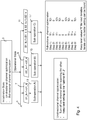
- FIG. 3 illustrates MetNet SON for densely packed DWDM channels.
- the left most column in the table seen in figure 3 represents six different examples A-F, the next column represents a cause, the middle column represents an effect, the next column to the right represents an action and the right most column comprises comments.
- D represents laser drift of either the first (1) channel 203 or the second (2) channel 205
- F represents filter drift
- B represents the BER.
- Tx2 is a longer wavelength than the Tx1 209 and that all events D1, D2, F are independent in figure 3 .
- An in-band communications channel is assumed in figure 3 so that effects are known at both sides.
- one side may function as the master controlling the tuning of the slave.
- the cause D1+ in figure 3 represents the Tx1 209 laser drift to a longer wavelength and the cause F+ represents filter drift to a longer wavelength.
- the effect B1+ in figure 3 represents the received BER increase (bad) at the Rx1 207 from the Tx1 209 assuming that each transceiver can estimate the received BER.
- the action T1+ represents the tuning of the Tx1 209 to a longer wavelength, e.g. fine tuning in 1 GHz steps, -15 to +15 GHz vs. nominal (corresponding for 1, 2, +, -).
- the cause may be a laser drift towards longer wavelengths (called positive, +) of the first channel (D1 + in the cause-column).
- the drift in Tx1 209 causes more Rayleigh backscatter from the signal transmitted from Tx1 209 onto the first receiver Rx1 207 which increases the BER B2 and B1.
- the center wavelength of the first channel 203 is tuned towards shorter wavelengths (in the negative direction, -) (T1- in the action-column).
- the cause may be a negative laser drift of the first channel 203 (D1- in the cause-column of figure 3 ).
- the drift of Tx1 209 drives the transmitted signal into the filter edge and attenuates the signal received by Rx1 207. This may also increase the B1 if the received signal quality is on the limit.
- B2 may be improved if the Rayleigh impairment is decreased.
- the center wavelength of the first channel should be tuned in a positive direction (T1+ in the action-column) to counter the laser drift.
- the cause may be a positive laser drift of the second channel 205 (D2+ in the cause-column).
- a positive laser drift of Tx2 drives the transmitted signal into the filter edge and degrades the signal received by Rx2 211.
- This may also increase the BER of the second channel 205 (B2) if the received power is on the limit. It should be appreciated that this may also improve the BER of the first channel 203 (B1) if the Rayleigh impairment is decreased.
- the center wavelength of the second channel 205 should be tuned in a negative direction (T2-in the action-column of figure 3 ).
- the cause may be a negative laser drift of the second channel 205 (D2- in the cause-column).
- a decreased drift of Tx2 213 causes more Rayleigh backscatter from the signal transmitted from Tx2 213 onto the signal received by Rx2 211. This will result in an increase of the BER B1 and vice versa B2.
- the center wavelength of the second channel should be tuned in the positive direction (T1+ in the action-column).
- the cause may be a negative filter drift (F- in the cause-column).
- a decrease in filter drift drives the filter edge into the Tx2 213 signal and attenuates the signal received by Rx2 211.
- the center wavelength of both the first and second channels 203, 205 should be tuned in the negative direction (T1-, T2- in the action-column of figure 3 ) to counter the effect of the filter drift.
- a cause D1+ may be that the Tx1 209 laser drifts to longer wavelength and a cause F+ may be that the filter drifts to a longer wavelength.
- the effect B1+ is that received BER increase (bad) at Rx1 207 from Tx1 209, assuming that each transceiver can estimate the received BER.
- the action T1+ is tuning of the Tx1 209 to longer wavelength, e.g. fine tuning in 1 GHz steps, -15 to +15 GHz vs. nominal (and corresponding for 1, 2, +, -).
- An increase in the BER of the first channel 203 may be the result of a positive filter or laser drift of the first channel 203 (F+, D1+).
- the center wavelength of the first channel may be tuned in a positive direction (T1+).
- a further evaluation may be made.
- an increase of B1 only may be detected.
- Increase in only B1 may be the result of the Tx1 209 laser drifting in a negative direction or the positive filter drift.
- the center wavelength of the first channel 203 is further tuned in the positive direction (T1+).
- the BER of both channels has increased (B1+ and B2+). This may be the result of a laser drift of Tx1 209. If the drift is towards the filter edge, only B1 has been affected in such case the center wavelength of the first channel 203 shall be tuned in the positive direction (T1+). If the drift is towards Tx2 213, both B1 and B2 are affected, in such a case the center wavelength of the first channel 203 is tuned in the negative direction (T1-). If it is determined that the cause is the laser drift of Tx2 213, both B1 and B2 are affected, in such a case the center wavelength of the second channel 205 shall be tuned in the positive direction (T2+).
- Figure 4 provides an overview of some of the example embodiments presented herein for a MetNet SON for densely packed DWDM channels.
- Figure 4 is a high level flow diagram comprising the predetermined profiles featuring the wavelength tuning adjustments which may be made taking into account the above assumptions.
- the wavelength tuning adjustments may be made dynamically during an iterative evaluation procedure.
- an initialization stage is performed (3).
- a BER for both the first and second channels 203, 205 is determined.
- This first BER is used during the first iteration of the iterative procedure (5).
- the first BER may be determined via one of two methods, i.e. unidirectional optimization and bidirectional optimization. According to some of the example embodiments, the first BER may be determined via the unidirectional channel optimization.
- an initial BER for each of the first and second channels 203, 205 is determined while the second and first channel, respectively, is in a non-transmission mode.
- a BER for the first and second channel 203, 205 is calculated when there are no transmissions occurring on the second and first channel 205, 203, respectively.
- One channel is turned off while scanning the other.
- the best settings are kept as the "optimal B1, 2".
- the initial BER may be determined via the bidirectional optimization.
- a BER for both the first and second channel 203, 205 is determined for respective combinations of different center wavelength.
- nine different center wavelength combinations of the first and second channels 203, 205 are utilized for BER calculations, illustrated as steps 1-9 in
- Step 1 comprises T1- and T2-
- step 2 comprises T1- and 0,
- step 3 comprises T1- and T2+
- step 4 comprises 0 and T2-
- step 5 comprises 0 and 0,
- step 6 comprises 0 and T2+
- step 7 comprises T1+ and T2-
- step 8 comprises T1+ and 0
- step 9 comprises T1+ and T2+.
- the best values "0" are kept for the next iteration, and the iteration is performed until no better setting can be found. It should be appreciated that the bidirectional optimization may comprise any number of combinations. Once the BER for both the first and second channel 203, 205 is calculated all the different combinations, the combination with the smallest BER value is utilized for the initial iteration.
- the iterative analysis commences (5).
- a BER later in time is calculated.
- a comparison of a current BER, for example, the BER of channel B1_k+1, with respect to an earlier calculated BER, for example, the earlier BER of channel B1_k is made.
- an identification is made as to whether the calculated or determined BERs fit into one of three categories or predetermined profiles.
- the first predetermined profile being an increase of a BER of only the first channel 203, for example, B1_k+1> B1_k (7).
- the second predetermined profile is an increase of a BER of only the second channel 205, for example, B2_k+1> B2_k(9).
- the third predetermined profile is an increase in both the BER of both the first and second channels 203, 205, for example, B1_k+1> B1_k and B2_k+1> B2_k (11).
- a respective set of sub-operations comprising various wavelength tuning, is performed (13, 15, 17), i.e. sub-operation A), B), C).
- Figure 5 illustrates a sequence of operations or wavelength tuning adjustments associated with the first predetermined profile, B1_k+1> B1_k (7), i.e. sub-operation A) in figure 4 .
- the circle 1 represent filter drift +
- the circle 2 represents T1 drift-
- the circle 3 represents filter narrowing
- the circle 4 represents channel degradation.
- a parallelogram represents an input event
- a rectangle represents an action
- a rectangle with rounded corners represents a test/condition.
- a center wavelength of the first channel 203 is tuned in a positive direction T1+ (21). Thereafter, another iteration is performed and further BER calculations are made. Thus, upon another iteration, the current BER of step 7 becomes the BER calculated earlier in time.
- the current BER of the first channel 203 (B1_k+2) is evaluated. If it is determined that the current BER of the first channel 203 is less than the previous BER calculated earlier in time (B1_k+2 ⁇ B1_k+1), it will be concluded that the wavelength tuning provided in operation 21 was successful (23). Thereafter, a new iteration will take place and an identification for one of the three predetermined profiles of figure 4 (7, 9, 11) will continue (5).
- the BER of the first channel 203 was not improved by the tuning provided in operation 21 (25).
- Channel degradation is assumed as the cause of the increased BER of the first channel, which is not something that is possible to be fixed via laser tuning. Therefore, the center wavelength of the first channel 203 is returned to its previous value via a tuning in the negative direction (27). Thereafter, a new iteration is performed and an identification for one of the three predetermined profiles of figure 4 (7, 9, 11) will continue (5).
- the BER of the first channel 203 is less than the previous BER calculated earlier in time (B1_k+3 ⁇ B1_k+2) and if the current BER of the second channel 205 is greater than or equal to the previous BER of the second channel 205 calculated earlier in time (B2_k+2 ⁇ B2_k+1), it is concluded the BER of the first channel 203 is improved but the BER of the second channel 205 has worsen (37). Filter narrowing is assumed as the cause for the increase of BER in the second channel 205. In such a case, the center wavelength of the second channel 205 is tuned in a negative direction T2- (39).
- Figure 6 illustrates a sequence of operations or wavelength tuning adjustments associated with the second predetermined profile, B2_k+1> B2_k (9), i.e. sub-operation B) in figure 4 .
- the circle 1 represent filter drift +
- the circle 2 represents T1 drift
- the circle 3 represents filter narrowing
- the circle 4 represents channel degradation.
- a parallelogram represents an input event
- a rectangle represents an action
- a rectangle with rounded corners represents a test/condition.
- a center wavelength of the second channel 205 is tuned in a negative direction T2- (43). Thereafter, another iteration is performed and further BER calculations are made. Thus, upon another iteration, the current BER of step 9 becomes the BER calculated earlier in time.
- the current BER of the second channel 205 (B2_k+2) is evaluated. If it is determined that the current BER of the second channel 205 is less than the previous BER calculated earlier in time (B2_k+2 ⁇ B2_k+1), it will be concluded that the wavelength tuning provided in operation 43 was successful (45). Thereafter, a new iteration will take place and an identification for one of the three predetermined profiles in figure 4 (7, 9, 11) will continue (5). In other words, the communications controller 215 undergoes a new iteration of the receiving (10, 12), comparing (14, 16), determining (18) and the sending (20) of the evaluating channel.
- the BER of the second channel 205 was not improved by the tuning provided in operation 43 (47).
- Channel degradation is assumed as the cause of the increased BER of the second channel 205, which is not something that is assumed possible to be fixed via laser tuning. Therefore, the center wavelength of the second channel 205 is returned to its previous value via tuning in the positive direction T2+ (49). Thereafter, a new iteration is performed and an identification for one of the three predetermined profiles in figure 4 (7, 9, 11) will continue (5).
- the BER of the second channel 205 is less than the previous BER calculated earlier in time (B2_k+3 ⁇ B2_k+2) and if the current BER of the first channel 203 is greater than or equal to the previous BER of the first channel 203 calculated earlier in time (B1_k+2 ⁇ B1_k+1), it is concluded the BER of the second channel 205 is improved but the BER of the first channel 203 has worsen (59). Filter narrowing is assumed as the cause for the increase of BER in the first channel 203. In such a case, the center wavelength of the first channel 203 is tuned in a positive direction T1+(61).
- Figure 7 illustrates a sequence of operations or wavelength tuning adjustments associated with the third predetermined profile, B1_k+1> B1_k and B2_k+1> B2_k (11), i.e. sub-operation C) in figure 4 .
- the circle 1 represent filter drift +
- the circle 2 represents T1 drift-
- the circle 3 represents channel degradation.
- a parallelogram represents an input event
- a rectangle represents an action
- a rectangle with rounded corners represents a test/condition.
- a center wavelength of the first channel 203 is tuned in a negative direction T1- (65).
- T1- (65) A possible cause for the BER of both channels to worsen is that the last associated with Tx1 209 has drifted toward the second channel 205. Therefore, the center wavelength of the first channel 203 is tuned in the negative direction. Thereafter, another iteration is performed and further BER calculations are made. Thus, upon another iteration, the current BER of step 11 becomes the BER calculated earlier in time.
- the center wavelengths of both the first and second channels 203, 205 are tuned in a positive direction, T1+ and T2+ (71).
- the center wavelength of the first channel 203 is tuned or tuned in the positive direction T1+ (75). Thereafter, a new iteration will take place and an identification for one of the three predetermined profiles of figure 4 (7, 9, 11) will continue (5).
- FIG 8 illustrates an example node configuration of a communications controller 215, according to some of the example embodiments described herein.
- the communications controller 215 may comprise control channel circuitry or a communication port 501 that may be configured to receive and/or transmit communication data, instructions, and/or messages or BER values.
- the control channel circuitry or communication port 501 may be comprised as any number of transceiving, receiving, and/or transmitting units or circuitry. It should further be appreciated that the control channel circuitry or communication port 501 may be in the form of any input/output communications port known in the art.
- the control channel circuitry or communication port 501 may comprise Radio Frequency (RF) circuitry and baseband processing circuitry (not shown).
- RF Radio Frequency
- the communications controller 215 may also comprise a processing unit or circuitry 503 which may be configured to provide wavelength control for a first and second channel 203, 205 as described herein.
- the processing circuitry 503 may be any suitable type of computation unit, e.g. a microprocessor, Digital Signal Processor (DSP), Field Programmable Gate Array (FPGA), or Application Specific Integrated Circuit (ASIC), or any other form of circuitry.
- the communications controller 215 may further comprise a memory unit or circuitry 505 which may be any suitable type of computer readable memory and may be of volatile and/or non-volatile type.
- the memory 505 may be configured to store received, transmitted, and/or measured data, device parameters, predetermined profile data, and/or executable program instructions.
- Figure 9 is a flow diagram depicting example operations which may be performed by the communications controller 215 as described herein to provide wavelength control for a first and second channel 203, 205, as described herein. It should be appreciated that Figure 9 comprises some operations which are illustrated with a solid border and some operations which are illustrated with a dashed border. The operations which are comprised in a solid border are operations which are comprised in the broadest example embodiment. The operations which are comprised in a dashed border are example embodiments which may be comprised in, or a part of, or are further operations which may be performed in addition to the operations of the broader example embodiments. It should be appreciated that these operations need not be performed in order. Furthermore, it should be appreciated that not all of the operations need to be performed. The example operations may be performed in any order and in any combination.
- wavelength control is provided for a first and second channel 203, 205, where the first and second channel 203, 205 are bidirectional and adjacent to one another in a single fiber in a DWDM based system, for example, as illustrated in Figure 2 .
- wavelength tuning instructions provide a tuning of a wavelength center of at least one of the first and second channel 203, 205 in one step, wherein a step is 0.5 GHz, 1 GHz, or 2 GHz.
- the communications controller 215 may be located within a receiver of at least one of the first and second channel, or the communications controller may be a central node.
- the communications controller 215 may be configured to receive 4, from respective transmitters of the first and second channels 203, 205, a plurality of initial bit error rate values of the first and second channels 203, 205 and choose the lowest one for an initial iteration (bidirectional initialization).
- the plurality of initial bit error rate values is obtained via different combinations of possible wavelength tuning values of the first and second channel 203, 205.
- a combination, of the different combinations possible, comprising a lowest bit error rate for the first and second channels 203, 205 is utilized in a first iteration of the wavelength control process described herein.
- the control channel circuitry 501 is configured to receive, from the respective transmitters of the first and second channels 203, 205, the plurality of initial bit error rate values of the first and second channels 203, 205.
- Example operation 4 is further described in at least Figure 4 .
- an initialization state 3 may be used to determine initial BER values for the iterative evaluation 5 in providing wavelength control for the first and second channels 203, 205.
- Example operation 4 is directed towards the bidirectional channel optimization where BER values are calculated for various combinations of wavelengths centers of the first and second channel 203, 205. A lowest combination of center wavelengths associated with a lowest BER is utilized for the initial iteration of the analysis 5.
- the communications controller 215 may be configured to receive 6, from the transmitter 209 of the first channel 203 an initial bit error rate of the first channel 203 obtained when the second channel 205 is in a non-transmission mode.
- the control channel circuitry 501 is configured to receive, from the transmitter 209 of the first channel 203, the initial bit error rate of the first channel 203 obtained when the second channel 205 is in a non-transmission mode (unidirectional initialization).
- Example operation 6 is described further in at least Figure 4 .
- an initialization state 3 may be used to determine initial BER values for the iterative evaluation 5 in providing wavelength control for the first and second channels 203, 205.
- Example operation 6 is directed towards unidirectional channel optimization where an initial BER for the first and second channel 203, 205 is obtained when the second and first channel 203, 205, respectively, is not transmitting.
- the communications controller 215 may be further configured to receive 8, from the transmitter 213 of the second channel 205, an initial bit error rate of the second channel 205 obtained when the first channel 203 is in a non-transmission mode.
- the initial bit error rates of the first and second channel 203, 205 are used in a first iteration of the iterative analysis 5.
- the control channel circuitry 501 is configured to receive, from the transmitter 213 of the second channel 205, the initial bit error rate of the second channel 205 obtained when the first channel 203 is in a non-transmission mode (unidirectional initialization).
- Example operation 8 is described further in at least Figure 4 .
- an initialization state 3 may be used to determine initial BER values for the iterative evaluation 5 in providing wavelength control for the first and second channels 203, 205.
- Example operation 8 is directed towards unidirectional channel optimization where an initial BER for the first and second channel 203, 205 is obtained when the second and first channel 203, 205, respectively, is not transmitting.
- the communications controller 215 is configured to receive 10, from a receiver 207 of the first channel 203 (Rx1), a current bit error rate of the first channel 203 (CH1).
- the control channel circuitry 501 is configured to receive, from the receiver 207 of the first channel 203, the current bit error rate of the first channel 203. It should be appreciated that the receiving described in operation 10 may occur during any time of the iterative process.
- the communications controller 215 is further configured to receive 12, from a receiver 211 of the second channel 205 (Rx2), a current bit error rate of the second channel 205 (CH2).
- the control circuitry 501 is configured to receive, from the receiver 211 of the second channel 205, the current bit error rate of the second channel 205. It should be appreciated that the receiving described in operation 12 may occur during any time of the iterative process.
- the communications controller 215 is further configured to compare 14 the current bit error rate of the first channel 203 (CH1) with a previous bit error rate of the first channel 203 (CH1).
- the previous bit error rate of the first channel 203 is determined at an earlier time as the current bit error rate of the first channel 203.
- the processing circuitry 503 is configured to compare the current bit error rate of the first channel 203 with a previous bit error rate of the first channel 203.
- the communications controller 215 is further configured to compare 16 the current bit error rate of the second channel 205 (CH2) with a previous bit error rate of the second channel 205 (CH2).
- the previous bit error rate of the second channel 205 is determined at an earlier time as the current bit error rate of the second channel 205.
- the processing circuitry 503 is configured to compare the current bit error rate of the second channel 205 with a previous bit error rate of the second channel 205.
- the communications controller 215 is also configured to identify 18 if the comparisons of operations 14 and 16 are equivalent to one of three predetermined profiles.
- the predetermined profiles are:
- the processing circuitry 503 is configured to identify if the comparisons of operations 14 and 16 are equivalent to one of three predetermined profiles.
- the communications controller 215 is further configured to send 20, to transmitter(s) 209, 213 of at least one of the first and second channel 203, 205 (Tx1, Tx2), wavelength tuning instructions to tune a center wavelength of at least one of the first and second channel 203, 205 based on the identified predetermined profile.
- Each of the three predetermined profiles comprises a respective set of wavelength tuning instructions.
- the control channel circuitry 501 is configured to send, to the transmitter(s) 209, 213 of at least one the first and second channel 203, 205, wavelength tuning instructions to tune a center wavelength of at least one of the first and second channel 203, 205 based on the identified predetermined profile.
- the wavelength tuning instructions provide tuning 22 a center wavelength of the evaluating channel by one step. If the evaluating channel is the first channel, the wavelength instructions provide a tuning of one step in a positive direction and if the evaluating channel is the second channel 205, the wavelength instructions provide a tuning of one step in a negative direction. A further iteration of operations 10, 12, 14, 16, 18 and 20 is thereafter commenced.
- Example operation 22 is further described in Figures 5 and 6 .
- Figure 5 describes the tuning instructions provided if the evaluating channel is the first channel 203. As shown in Figure 5 , upon an evaluation of B1_k+1> B1_k (7), the center wavelength of the first channel 203 is tuned in a positive direction T1+ and T2- (21).
- Figure 6 describes the tuning instructions provided if the evaluating channel is the second channel 205.
- the center wavelength of the second channel 205 is tuned in a negative direction (43).
- the wavelength tuning instructions provide tuning 24 a center wavelength of the evaluating channel by one step. If the evaluating channel is the first channel 203, the wavelength instructions provide a tuning of one step in a negative direction and if the evaluating channel is the second channel 205, the wavelength instructions provide a tuning of one step in a positive direction. A further iteration of operations 10, 12, 14, 16, 18 and 20 is thereafter commenced.
- Example operation 24 is further described in Figures 5 and 6 .
- Figure 5 describes the tuning instructions provided in the evaluating channel is the first channel 203. As shown in Figure 5 , upon an evaluation of B1_k+2 ⁇ B1_k+1 (25), the center wavelength of the first channel 203 is tuned in a negative direction T1- (27).
- Figure 6 describes the tuning instructions provided if the evaluating channel is the second channel 205. As shown in Figure 6 , upon an evaluation of B2_k+2 ⁇ B2_k+1 (47), the center wavelength of the second channel 205 is tuned in a positive direction T2+ (49).
- the wavelength tuning instructions provide a tuning 26 of a center wavelength of either the first or second channel 203, 205 by one step. If the evaluating channel is the first channel 203, the wavelength instructions provide a tuning of the center wavelength of the second channel 205 one step in a positive direction. If the evaluating channel is the second channel 205, the wavelength instructions provide a tuning of the center wavelength of the first channel 203 one step in a negative direction. A further iteration of operations 10, 12, 14, 16, 18 and 20 of the evaluating channel is thereafter commenced.
- Example operation 26 is further explained in Figures 5 and 6 .
- Figure 5 describes the tuning instructions provided in the evaluating channel is the first channel 203.
- the center wavelength of the second channel 205 is tuned in a positive direction T2+(31).
- Figure 6 describes the tuning instructions provided if the evaluating channel is the second channel 205.
- the center wavelength of the first channel is tuned in a negative direction, T1- (53).
- the wavelength tuning instructions provide tuning 28 a center wavelength of the evaluating channel by one step. If the evaluating channel is the first channel 203, the wavelength instructions provide a tuning of the first channel 203 in a negative direction. If the evaluating channel is the second channel 205, the wavelength instructions provide a tuning of the center wavelength of the second channel one step in a positive direction. A further iteration of operations 10, 12, 14, 16, 18 and 20 is thereafter commenced.
- Example operation 28 is further explained in Figures 5 and 6 .
- Figure 5 describes the tuning instructions provided that the evaluating channel is the first channel 203. As shown in Figure 5 , upon an evaluation of B1_k+3 ⁇ B1_k+2 (33), the center wavelength of the first channel 203 is tuned in a negative direction T1- (35).
- Figure 6 describes the tuning instructions provided if the evaluating channel is the second channel 205. As shown in Figure 6 , upon an evaluation of B2_k+3 ⁇ B2_k+2 (55), the center wavelength of the second channel 205 is tuned in a positive direction T2+ (57).
- the wavelength turning instructions provide tuning 30 a center wavelength of either the first or second channel 203, 205 by one step. If the evaluating channel is the first channel 203, the wavelength instructions provide a tuning of the center wavelength of the second channel 205 one step in a negative direction. If the evaluating channel is the second channel 205, the wavelength instructions provide a tuning of the center wavelength of the first channel 203 one step in a positive direction. A further iteration of operations 10, 12, 14, 16, 18 and 20 is thereafter commenced.
- Example operation 30 is further explained in Figures 5 and 6 .
- Figure 5 describes the tuning instructions provided if the evaluating channel is the first channel 203. As shown in Figure 5 , upon an evaluation of B1_k+3 ⁇ B1_k+2 and B2_k+2 ⁇ B1_k+1 (37), the center wavelength of the second channel 205 is tuned in a negative direction T2- (39).
- Figure 6 describes the tuning instructions provided if the evaluating channel is the second channel 205. As shown in Figure 6 , upon an evaluation of B2_k+3 ⁇ B2_k+2 and B1_k+2 ⁇ B1_k+1 (59), the center wavelength of the first channel 203 is tuned in a positive direction T1 + (61).
- the wavelength turning instructions provide tuning 32 a center wavelength of the first channel 203 one step in a negative direction. A further iteration of operations 10, 12, 14, 16, 18 and 20 is thereafter commenced.
- Example operation 32 is further explained in at least Figures 4 and 7 .
- the evaluation of B1_k+1> B1_k and B2_k+1> B2_k(11) is the third predetermined profile.
- sub-operations C as provided in Figure 7 are commenced.
- One possible cause for the BER of both channels to increase is because the laser associated with Tx1 209 has drifted towards the second channel, thus the center wavelength of the first channel 203 is tuned.
- the center wavelength of the first channel 203 is tuned in a negative direction T1- (65).
- the wavelength tuning instructions provide tuning 34 a center wavelength of both the first and second channel 203, 205 by one step in a positive direction. A further iteration of operations 10, 12, 14, 16, 18 and 20 is thereafter commenced.
- Example operation 34 is further described in at least Figure 7 .
- the center wavelengths of both the first and second channels 203, 205 are tuned in a positive direction T1+ and T2+ (71).
- the wavelength tuning instructions provide tuning 36 a center wavelength of the first channel 203 by one step in a positive direction. A further iteration of operations 10, 12, 14, 16, 18 and 20 is thereafter commenced.
- Example operation 36 is further described in at least Figure 7 .
- the current BER of the first channel 203 is greater than or equal to the previous BER of the first channel 203 calculated earlier in time from two previous iterations (B1_k+2 ⁇ B1_k)
- B1_k+2 ⁇ B1_k previous BER of the first channel 203
- channel degradation is assumed to be the cause for the increase of the BER of the first channel 203.
- the center wavelength of the first channel 203 is tuned or tuned in the positive direction T1+ (75).
- HSPA High Speed Packet Access
- WCDMA Wideband Code Division Multiple Access
- WiMax Worldwide Interoperability for Microwave Access
- UMB Ultra Mobile Broadband
- WiFi Global System for Mobile Communications
- a wireless terminal or User Equipment (UE) as the term is used herein, is to be broadly interpreted to comprise a radiotelephone having ability for Internet/intranet access, web browser, organizer, calendar, a camera, e.g., video and/or still image camera, a sound recorder, e.g., a microphone, and/or Global Positioning System (GPS) receiver; a Personal Communications System (PCS) user equipment that may combine a cellular radiotelephone with data processing; a Personal Digital Assistant (PDA) that can comprise a radiotelephone or wireless communication system; a laptop; a camera, e.g., video and/or still image camera, having communication ability; and any other computation or communication device capable of transceiving, such as a personal computer, a home entertainment system, a television, etc.
- PDA Personal Digital Assistant
- the term user equipment may also comprise any number of connected devices, wireless terminals or machine-to-machine devices.
- dual connectivity should not be limited to a user equipment or wireless terminal being connected to only two base stations.
- a wireless terminal may be connected to any number of base stations.
- a computer-readable medium may comprise removable and non-removable storage devices comprising, but not limited to, Read Only Memory (ROM), Random Access Memory (RAM), Compact Discs (CDs), Digital Versatile Discs (DVD), etc.
- program modules may comprise routines, programs, objects, components, data structures, etc. that perform particular tasks or implement particular abstract data types.
- Computer-executable instructions, associated data structures, and program modules represent examples of program code for executing steps of the methods disclosed herein. The particular sequence of such executable instructions or associated data structures represents examples of corresponding acts for implementing the functions described in such steps or processes.
- the computer-readable medium has computer-executable instructions for managing a communications controller 215 for wavelength control of a first 203 and second channel 205.
- Said first 203 and second channel 205 are bidirectional and adjacent to one another in a single fiber in a DWDM based system.
- the instructions comprising receiving, from a receiver 207 of the first channel 203, a current bit error rate of the first channel 20, and receiving, from a receiver 211 of the second channel 205 a current bit error rate of the second channel 205.
- the instructions further comprise comparing the current bit error rate of the first channel 203 with a previous bit error rate of the first channel 203. Said previous bit error rate of the first channel 203 is determined at an earlier time as said current bit error rate of the first channel 203.
- the instructions comprise comparing the current bit error rate of the second channel 205 with a previous bit error rate of the second channel 205. Said previous bit error rate of the second channel 205 is determined at an earlier time as said current bit error rate of the second channel 205.
- the instructions comprise identifying if said comparing is equivalent to one of three predetermined profiles.
- Said predetermined profiles being said current bit error rate for the first channel 203 is greater than said first previous bit error rate of the first channel 203.
- Said current bit error rate of the second channel 205 is greater than said previous bit error rate of the second channel 205, or said current bit error rate of the first 203 and second channel 205 is greater than said previous bit error rate of the first 203 and second channel 205, respectively.
- the instructions comprise sending, to transmitter(s) 209, 213 of at least one of the first 203 and second channel 203, a set of wavelength tuning instructions to tune a center wavelength of at least one of the first 203 and second channel 203 based on the identified predetermined profile.
- Wach of the three predetermined profiles comprises a respective set of wavelength tuning instructions.
Landscapes
- Engineering & Computer Science (AREA)
- Computer Networks & Wireless Communication (AREA)
- Signal Processing (AREA)
- Physics & Mathematics (AREA)
- Electromagnetism (AREA)
- Optical Communication System (AREA)
Claims (15)
- Procédé, dans un contrôleur de communications (215), pour le contrôle de longueurs d'ondes d'un premier et d'un second canal, lesdits premier (203) et second (205) canaux étant bidirectionnels et adjacents l'un de l'autre dans une fibre unique dans un système basé sur le multiplexage en longueurs d'onde denses, DWDM, le procédé comprenant :la réception (10), depuis un récepteur (207) du premier canal (203), d'un taux d'erreur binaire courant du premier canal (203) ;la réception (12), d'un récepteur (211) du second canal (205), d'un taux d'erreur binaire courant du second canal (205) ;caractérisé en ce que le procédé comprend en outre :la comparaison (14) du taux d'erreur binaire courant du premier canal (203) à un taux d'erreur binaire précédent du premier canal (203), ledit taux d'erreur binaire précédent du premier canal (203) étant déterminé plus tôt que ledit taux d'erreur binaire du premier canal (203) ;la comparaison (16) du taux d'erreur binaire courant du second canal (205) à un taux d'erreur binaire précédent du second canal (205), ledit taux d'erreur binaire précédent du second canal étant déterminé plus tôt que ledit taux d'erreur binaire courant du second canal (205) ;l'identification (18) visant à indiquer si ladite comparaison (14, 16) est équivalente à l'un de trois profils prédéterminés, lesdits profils prédéterminés étant ledit taux d'erreur binaire courant pour le premier canal (203) qui est supérieur audit premier taux d'erreur binaire précédent du premier canal (203), ledit taux d'erreur binaire courant du second canal (205) qui est supérieur audit taux d'erreur binaire précédent du second canal (205) ou ledit taux d'erreur binaire courant du premier (203) et du second canal (205) qui est supérieur audit taux d'erreur binaire précédent du premier (203) et du second (205) canal, respectivement ; etl'envoi (20), à un ou des émetteurs (209, 213) d'au moins l'un du premier (203) et du second (205) canal d'un ensemble d'instructions de réglage de longueurs d'ondes pour s'accorder sur une longueur d'ondes centrale d'au moins l'un du premier (203) et du second (205) canal sur la base du profil prédéterminé identifié, dans lequel chacun des trois profils prédéterminés comprend un ensemble respectif d'instructions de réglage de longueurs d'ondes.
- Procédé selon la revendication 1, dans lequel la réception (10, 12), la comparaison (14, 16), la détermination (18) et l'envoi (20) sont effectués en mode itératif.
- Procédé selon la revendication 2, comprenant en outre :la réception (6), de l'émetteur (209) du premier canal (203), d'un taux d'erreur binaire initial du premier canal obtenu lorsque ledit second canal (205) est en mode de non-transmission ; etla réception (8), de l'émetteur (213) du second canal (205), d'un taux d'erreur binaire initial du second canal (205) obtenu lorsque ledit premier canal (203) est dans un mode de non-transmission, dans lequel lesdits taux d'erreurs binaires initiaux du premier (203) et du second (205) canal sont utilisés dans une première itération de la réception (10, 12), de la comparaison (14, 16), de la détermination (18) et de l'envoi (20).
- Procédé selon la revendication 2, comprenant en outre :la réception (4), d'émetteurs respectifs (209, 213) du premier (205) et du second (205) canal, d'une pluralité de valeurs de taux d'erreurs binaires initiaux du premier (203) et du second (205) canal, dans lequel ladite pluralité de valeurs de taux d'erreurs binaires initiaux est obtenue via différentes combinaisons de valeurs de réglage de longueurs d'ondes possibles du premier (203) et du second (205) canal, et dans lequel une combinaison des différentes combinaisons possibles comprenant un taux d'erreur binaire le plus bas pour le premier (203) et le second (205) canal est utilisée dans une première itération de la réception (10, 12), de la comparaison (14, 16), de la détermination (18) et de l'envoi (20).
- Procédé selon l'une quelconque des revendications 2 à 4, dans lequel si un taux d'erreur binaire courant d'un canal d'évaluation, qui est le premier (203) ou le second (205) canal, est supérieur à un taux d'erreur binaire précédent du canal d'évaluation, les instructions de réglage de longueurs d'ondes fournissent un réglage (22) d'une longueur d'ondes centrale dudit canal d'évaluation d'un pas, dans lequel, si le canal d'évaluation est le premier canal (203), les instructions de réglage de longueurs d'ondes fournissent un réglage d'un pas dans un sens positif et si le canal d'évaluation est le second canal, les instructions de réglage de longueurs d'ondes fournissent un réglage d'un pas dans un sens négatif ; et
dans lequel le procédé comprend en outre :la soumission d'une nouvelle itération de la réception (10, 12), de la comparaison (14, 16), de la détermination (18) et de l'envoi (20). - Procédé selon l'une quelconque des revendications 2 à 4, dans lequel si un taux d'erreur binaire courant à la fois du premier et du second canal (205) est supérieur à un taux d'erreur binaire précédent du premier (203) et du second (205) canal, respectivement, les instructions de réglage de longueurs d'ondes fournissent un réglage (32) d'une longueur d'onde centrale du premier canal (203) d'un pas dans le sens négatif ; et
dans lequel le procédé comprend en outre :la soumission d'une nouvelle itération de la réception (10, 12), de la comparaison (14, 16), de la détermination (18) et de l'envoi (20). - Procédé selon l'une quelconque des revendications 1 à 6, dans lequel les instructions de réglage de longueurs d'ondes fournissent un réglage d'une longueur d'ondes centrale d'au moins l'un du premier (203) et du second (205) canal en un pas, dans lequel un pas est de 0,5 GHz, 1 GHz ou 2 GHz.
- Contrôleur de communications (215) pour le contrôle de longueurs d'ondes d'un premier (203) et d'un second (205) canal, lesdits premier (203) et second (205) canaux étant bidirectionnels et adjacents l'un à l'autre dans une fibre unique d'un système basé sur un multiplexage en longueurs d'ondes denses, DWDM, le contrôleur de communications (215) comprenant :une circuiterie de canaux de commande (501) configurée pour :recevoir, d'un récepteur (207) d'un premier canal (203), un taux d'erreur binaire courant du premier canal (203) ; et pourrecevoir d'un récepteur (211) du second canal (205), un taux d'erreur binaire courant du second canal (205) ;caractérisé en ce que le contrôleur de communications (215) comprend en outre :une circuiterie de traitement (503) configurée pour :comparer le taux d'erreur binaire courant du premier canal (203) à un taux d'erreur binaire précédent du premier canal (203), ledit taux d'erreur binaire précédent du premier canal (203) étant déterminé plus tôt que ledit taux d'erreur binaire courant du premier canal (203) ;comparer le taux d'erreur binaire courant du second canal (205) à un taux d'erreur binaire précédent du second canal (205), ledit taux d'erreur binaire précédent du second canal (205) étant déterminé plus tôt que ledit taux d'erreur binaire courant du second canal (205) ; et pouridentifier le fait que ladite comparaison est ou non équivalente à l'un de trois profils prédéterminés,lesdits profils prédéterminés étant ledit taux d'erreur binaire courant pour le premier canal (203) qui est supérieur audit premier taux d'erreur binaire précédent du premier canal (203), ledit taux d'erreur binaire courant du second canal (205) qui est supérieur audit taux d'erreur binaire précédent du second canal (205) ou ledit taux d'erreur binaire courant du premier (203) et du second (205) canal qui est supérieur audit taux d'erreur binaire précédent du premier (203) et du second (205) canal, respectivement ; etdans lequel ladite circuiterie de canaux de commande (501) est en outre configurée pour :envoyer, à un ou des émetteurs (209, 213) d'au moins l'un des premier (203) et second (205) canaux, un ensemble d'instructions de réglage de longueurs d'ondes pour s'accorder sur une longueur d'ondes centrale d'au moins l'un du premier (203) et du second (205) canal sur la base du profil prédéterminé identifié, dans lequel chacun des trois profils prédéterminés comprend un ensemble respectif d'instructions de réglage de longueurs d'ondes.
- Contrôleur de communications (215) selon la revendication 8, dans lequel la circuiterie de canaux de commande (501) est en outre configurée pour recevoir et envoyer de manière itérative ; et
dans lequel ladite circuiterie de traitement (503) est en outre configurée pour comparer et identifier en mode itératif. - Contrôleur de communications (215) selon la revendication 9, dans lequel la circuiterie de canaux de commande (501) est en outre configurée pour :recevoir, de l'émetteur (209) du premier canal (203), un taux d'erreur binaire initial du premier canal (203) obtenu lorsque ledit second canal (205) est en mode de non-transmission ; et pour recevoir, de l'émetteur (213) du second canal (205), un taux d'erreur binaire initial du second canal (205) obtenu lorsque ledit premier canal (203) est en mode de non-transmission, etdans lequel lesdits taux d'erreurs binaires initiaux du premier (203) et du second (205) canal sont utilisés dans une première itération de la réception et de l'envoi de la circuiterie de canaux de commande (501), et de la comparaison et de l'identification de la circuiterie de traitement (503).
- Contrôleur de communications (215) selon la revendication 9, dans lequel la circuiterie de canaux de commande (501) est en outre configurée pour :Recevoir, d'émetteurs respectifs (209, 213) du premier (203) et du second (205) canal, une pluralité de valeurs de taux d'erreur binaire initiales du premier (203) et du second (205) canal, dans lequel ladite pluralité de valeurs de taux d'erreurs binaires initiales est obtenue par différentes combinaisons de valeurs de réglage de longueurs d'ondes possibles du premier (203) et du second (205) canal, et dans lequel une combinaison, des différentes combinaisons possibles, comprenant un taux d'erreur binaire le plus bas pour le premier (203) et le second (205) canal est utilisée dans une première itération de la réception et de l'envoi de la circuiterie de canaux de commande (501), et de la comparaison et de l'identification de la circuiterie de traitement (503).
- Contrôleur de communications (215) selon l'une quelconque des revendications 9 à 11, dans lequel, si un taux d'erreur binaire courant d'un canal d'évaluation qui est le premier (203) ou le second (205) canal est supérieur à un taux d'erreur binaire précédent du canal d'évaluation, les instructions de réglage de longueurs d'ondes fournissent un réglage sur une longueur d'onde centrale dudit canal d'évaluation d'un pas ;
dans lequel, si le canal d'évaluation est le premier canal (203), les instructions de réglage de longueurs d'ondes fournissent un réglage d'un pas dans un sens positif et si le canal d'évaluation est le second canal (205), les instructions de réglage de longueurs d'ondes fournissent un réglage d'un pas dans le sens négatif ; et
dans lequel la circuiterie de canaux de commande (501) est en outre configurée pour subir une nouvelle itération de réception et d'envoi, et la circuiterie de traitement (503) est configurée pour subir une nouvelle itération de comparaison et d'identification. - Contrôleur de communications (215) selon l'une quelconque des revendications 9 à 11, dans lequel, si un taux d'erreur binaire courant à la fois du premier (203) et du second (205) canal est supérieur à un taux d'erreur binaire précédent du premier et du second canal, respectivement, les instructions de réglage de longueurs d'ondes fournissent un réglage sur une longueur d'ondes centrale du premier canal (203) d'un pas dans le sens négatif ; et
dans lequel la circuiterie de canaux de commande (501) est en outre configurée pour subir une nouvelle itération de réception et d'envoi, et la circuiterie de traitement (503) est configurée pour subir une nouvelle itération de comparaison et d'identification. - Contrôleur de communications (215) selon l'une quelconque des revendications 8 à 13, dans lequel les instructions de réglage de longueurs d'ondes fournissent un réglage sur une longueur d'ondes centrale d'au moins l'un du premier (203) et du second (205) canal en un pas, dans lequel un pas est de 0,5 GHz, 1 GHz ou 2 GHz.
- Support lisible sur ordinateur ayant des instructions exécutables sur ordinateur pour gérer un contrôleur de communications (215) pour le contrôle de longueurs d'ondes d'un premier (203) et d'un second (205) canal, lesdits premier (203) et second (205) canaux étant bidirectionnels et adjacents l'un à l'autre dans une fibre unique d'un système basé sur le multiplexage en longueurs d'ondes denses, DWDM, les instructions comprenant :la réception, d'un récepteur (207) du premier canal (203), d'un taux d'erreur binaire courant du premier canal (203) ;la réception, d'un récepteur (211) du second canal (205), d'un taux d'erreur binaire courant du second canal (205) ;caractérisé en ce que les instructions comprennent en outre :la comparaison du taux d'erreur binaire courant du premier canal (203) à un taux d'erreur binaire précédent du premier canal (203), ledit taux d'erreur binaire précédent du premier canal (203) étant déterminé plus tôt que ledit taux d'erreur binaire du premier canal(203);la comparaison du taux d'erreur binaire courant du second canal (205) à un taux d'erreur binaire précédent du second canal (205), ledit taux d'erreur binaire précédent du second canal (205) étant déterminé plus tôt que ledit taux d'erreur binaire courant du second canal (205);l'identification visant à indiquer si ladite comparaison est équivalente à l'un de trois profils prédéterminés, lesdits profils prédéterminés étant ledit taux d'erreur binaire courant pour le premier canal (203) qui est supérieur audit premier taux d'erreur binaire précédent du premier canal (203), ledit taux d'erreur binaire courant du second canal (205) qui est supérieur audit taux d'erreur binaire précédent du second canal (205), ou ledit taux d'erreur binaire courant du premier (203) et du second canal (205) qui est supérieur audit taux d'erreur binaire précédent du premier (203) et du second (205) canal, respectivement ; etl'envoi, à un ou des émetteurs (209, 213) d'au moins l'un du premier (203) et du second (205) canal, d'un ensemble d'instructions de réglage de longueurs d'ondes pour s'accorder sur une longueur d'ondes centrale d'au moins l'un du premier (203) et du second (205) canal sur la base du profil prédéterminé identifié, dans lequel chacun des trois profils prédéterminés comprend un ensemble respectif d'instructions de réglage de longueurs d'ondes.
Applications Claiming Priority (2)
| Application Number | Priority Date | Filing Date | Title |
|---|---|---|---|
| US201361887473P | 2013-10-07 | 2013-10-07 | |
| PCT/SE2013/051342 WO2015053675A1 (fr) | 2013-10-07 | 2013-11-15 | Contrôleur de communication et procédé de commande de longueur d'onde |
Publications (2)
| Publication Number | Publication Date |
|---|---|
| EP3055935A1 EP3055935A1 (fr) | 2016-08-17 |
| EP3055935B1 true EP3055935B1 (fr) | 2017-09-13 |
Family
ID=49713439
Family Applications (1)
| Application Number | Title | Priority Date | Filing Date |
|---|---|---|---|
| EP13799694.8A Active EP3055935B1 (fr) | 2013-10-07 | 2013-11-15 | Contrôleur de communication et procédé de commande de longueur d'onde |
Country Status (3)
| Country | Link |
|---|---|
| US (1) | US9654212B2 (fr) |
| EP (1) | EP3055935B1 (fr) |
| WO (1) | WO2015053675A1 (fr) |
Families Citing this family (4)
| Publication number | Priority date | Publication date | Assignee | Title |
|---|---|---|---|---|
| CN105960763B (zh) * | 2013-12-02 | 2020-03-03 | Oe解决方案美国有限公司 | 光收发器及光通信系统 |
| EP3288195B1 (fr) * | 2016-08-22 | 2019-04-24 | Mitsubishi Electric R&D Centre Europe B.V. | Procédé pour détecter un diviseur à une longueur d'ondes de désaccord dans un réseau de transmission à fibre optique |
| US20180109317A1 (en) * | 2016-10-13 | 2018-04-19 | Finisar Corporation | Bi-directional propagation in optical communication |
| US11239919B2 (en) * | 2018-12-20 | 2022-02-01 | Acacia Communications, Inc. | Side channel communication for an optical coherent transceiver |
Family Cites Families (16)
| Publication number | Priority date | Publication date | Assignee | Title |
|---|---|---|---|---|
| US6658210B1 (en) * | 1999-06-04 | 2003-12-02 | Worldcom, Inc. | Interleaved bidirectional WDM channel plan |
| WO2002103948A1 (fr) * | 2001-06-13 | 2002-12-27 | Fujitsu Limited | Systeme de communication optique |
| US6685210B2 (en) * | 2001-08-17 | 2004-02-03 | Cequent Towing Products, Inc. | Adjustable fifth wheel hitch with rollers |
| US20030058509A1 (en) * | 2001-09-24 | 2003-03-27 | Ditech Communications Corporation | Optical vestigial sideband (VSB) transmission |
| US7149424B2 (en) * | 2002-08-22 | 2006-12-12 | Siemens Communications, Inc. | Method and device for evaluating and improving the quality of transmission of a telecommunications signal through an optical fiber |
| US20050025486A1 (en) * | 2003-08-01 | 2005-02-03 | Johnny Zhong | Bi-directional wavelength division multiplexing module |
| JP2005341392A (ja) * | 2004-05-28 | 2005-12-08 | Fujitsu Ltd | 光伝送装置、光伝送システムおよび分散補償方法 |
| ITMI20041493A1 (it) * | 2004-07-23 | 2004-10-23 | Marconi Comm Spa | "pre-enfasi di canale basata sul ber in sistemi di communicazione wdm" |
| JP4571054B2 (ja) * | 2005-09-30 | 2010-10-27 | 富士通株式会社 | 光波長制御方法及びそのシステム |
| WO2008081545A1 (fr) * | 2006-12-28 | 2008-07-10 | Fujitsu Limited | Dispositif et procédé de transmission optique |
| US8045852B2 (en) * | 2008-04-23 | 2011-10-25 | Alcatel Lucent | Channel balancing algorithm |
| US8090258B2 (en) * | 2008-09-19 | 2012-01-03 | Tellabs Petaluma, Inc. | Method and apparatus for correcting faults in a passive optical network |
| JP2010226169A (ja) * | 2009-03-19 | 2010-10-07 | Fujitsu Ltd | 光送信装置、光通信方法および光通信システム |
| US8660428B2 (en) | 2010-12-31 | 2014-02-25 | Infinera Corporation | Variable channel spacing in a coherent transmission system |
| JP5863545B2 (ja) * | 2012-04-18 | 2016-02-16 | 株式会社日立製作所 | データ伝送システム、およびデータ伝送装置 |
| US8917988B2 (en) * | 2012-12-07 | 2014-12-23 | At&T Intellectual Property I, L.P. | End-to-end carrier frequency control to improve bandwidth utilization in an optical network |
-
2013
- 2013-11-15 EP EP13799694.8A patent/EP3055935B1/fr active Active
- 2013-11-15 WO PCT/SE2013/051342 patent/WO2015053675A1/fr not_active Ceased
- 2013-11-15 US US15/027,554 patent/US9654212B2/en not_active Expired - Fee Related
Non-Patent Citations (1)
| Title |
|---|
| None * |
Also Published As
| Publication number | Publication date |
|---|---|
| US20160269109A1 (en) | 2016-09-15 |
| US9654212B2 (en) | 2017-05-16 |
| EP3055935A1 (fr) | 2016-08-17 |
| WO2015053675A1 (fr) | 2015-04-16 |
Similar Documents
| Publication | Publication Date | Title |
|---|---|---|
| US20240396619A1 (en) | Beam failure recovery for single dci-based m-trp urllc transmissions | |
| US9667346B2 (en) | Optical transmission system, wavelength control method and node | |
| US11540149B2 (en) | Synchronization and fault management in a distributed antenna system | |
| JP5774726B2 (ja) | 同調不能な従来型onuを備えるwdmpon | |
| EP3055935B1 (fr) | Contrôleur de communication et procédé de commande de longueur d'onde | |
| US9136944B2 (en) | Measurement device, measurement method, transfer device, and optical network | |
| US20180205478A1 (en) | Method and Apparatus for Determining Propagation Delay in a Communications Network | |
| US10911127B2 (en) | Beam management of a radio transceiver device | |
| US20170006362A1 (en) | Optical burst transport network, node, transmission method and computer storage medium | |
| JP2016051988A (ja) | 光伝送システムおよび光伝送装置 | |
| JP2017510227A (ja) | 光伝送信号の等化方法 | |
| CN116235622A (zh) | 反射节点与网络节点之间链路故障的处理 | |
| HK1252535A1 (zh) | 针对授权辅助接入的接收信号强度指示符测量 | |
| JP5137906B2 (ja) | 光アクセス網、光加入者装置および光アクセス網の通信設定方法 | |
| US9306664B1 (en) | In-service optical signal to noise ratio monitoring in an optical network | |
| US20250167885A1 (en) | Optical communication system, master station device, slave station device, and optical communication method | |
| US12598005B2 (en) | Station side optical line terminal and registration method | |
| RU2746207C1 (ru) | Способ и устройство беспроводной связи | |
| US20150055947A1 (en) | Method for quick automatic remote wavelength discovery and configuration | |
| US10284324B2 (en) | Methods and apparatus for multiplexing and demultiplexing signals | |
| US9641277B2 (en) | Optical signal transmission method, apparatus and system | |
| WO2022053133A1 (fr) | Réflectométrie optique en domaine temporel désagrégée accordée en lambda | |
| US20160087746A1 (en) | Transmission system and transmission method | |
| US12609749B2 (en) | Polarization based beam selection process | |
| CN113922915A (zh) | Dml光模块波长自动纠偏方法、dml光模块及dwdm系统 |
Legal Events
| Date | Code | Title | Description |
|---|---|---|---|
| PUAI | Public reference made under article 153(3) epc to a published international application that has entered the european phase |
Free format text: ORIGINAL CODE: 0009012 |
|
| 17P | Request for examination filed |
Effective date: 20160408 |
|
| AK | Designated contracting states |
Kind code of ref document: A1 Designated state(s): AL AT BE BG CH CY CZ DE DK EE ES FI FR GB GR HR HU IE IS IT LI LT LU LV MC MK MT NL NO PL PT RO RS SE SI SK SM TR |
|
| AX | Request for extension of the european patent |
Extension state: BA ME |
|
| DAX | Request for extension of the european patent (deleted) | ||
| GRAP | Despatch of communication of intention to grant a patent |
Free format text: ORIGINAL CODE: EPIDOSNIGR1 |
|
| INTG | Intention to grant announced |
Effective date: 20170522 |
|
| GRAS | Grant fee paid |
Free format text: ORIGINAL CODE: EPIDOSNIGR3 |
|
| GRAJ | Information related to disapproval of communication of intention to grant by the applicant or resumption of examination proceedings by the epo deleted |
Free format text: ORIGINAL CODE: EPIDOSDIGR1 |
|
| GRAL | Information related to payment of fee for publishing/printing deleted |
Free format text: ORIGINAL CODE: EPIDOSDIGR3 |
|
| GRAR | Information related to intention to grant a patent recorded |
Free format text: ORIGINAL CODE: EPIDOSNIGR71 |
|
| INTC | Intention to grant announced (deleted) | ||
| GRAA | (expected) grant |
Free format text: ORIGINAL CODE: 0009210 |
|
| AK | Designated contracting states |
Kind code of ref document: B1 Designated state(s): AL AT BE BG CH CY CZ DE DK EE ES FI FR GB GR HR HU IE IS IT LI LT LU LV MC MK MT NL NO PL PT RO RS SE SI SK SM TR |
|
| INTG | Intention to grant announced |
Effective date: 20170808 |
|
| REG | Reference to a national code |
Ref country code: GB Ref legal event code: FG4D |
|
| REG | Reference to a national code |
Ref country code: CH Ref legal event code: EP |
|
| REG | Reference to a national code |
Ref country code: IE Ref legal event code: FG4D |
|
| REG | Reference to a national code |
Ref country code: AT Ref legal event code: REF Ref document number: 929113 Country of ref document: AT Kind code of ref document: T Effective date: 20171015 |
|
| REG | Reference to a national code |
Ref country code: DE Ref legal event code: R096 Ref document number: 602013026650 Country of ref document: DE |
|
| REG | Reference to a national code |
Ref country code: NL Ref legal event code: MP Effective date: 20170913 |
|
| REG | Reference to a national code |
Ref country code: LT Ref legal event code: MG4D |
|
| PG25 | Lapsed in a contracting state [announced via postgrant information from national office to epo] |
Ref country code: FI Free format text: LAPSE BECAUSE OF FAILURE TO SUBMIT A TRANSLATION OF THE DESCRIPTION OR TO PAY THE FEE WITHIN THE PRESCRIBED TIME-LIMIT Effective date: 20170913 Ref country code: HR Free format text: LAPSE BECAUSE OF FAILURE TO SUBMIT A TRANSLATION OF THE DESCRIPTION OR TO PAY THE FEE WITHIN THE PRESCRIBED TIME-LIMIT Effective date: 20170913 Ref country code: NO Free format text: LAPSE BECAUSE OF FAILURE TO SUBMIT A TRANSLATION OF THE DESCRIPTION OR TO PAY THE FEE WITHIN THE PRESCRIBED TIME-LIMIT Effective date: 20171213 Ref country code: LT Free format text: LAPSE BECAUSE OF FAILURE TO SUBMIT A TRANSLATION OF THE DESCRIPTION OR TO PAY THE FEE WITHIN THE PRESCRIBED TIME-LIMIT Effective date: 20170913 Ref country code: SE Free format text: LAPSE BECAUSE OF FAILURE TO SUBMIT A TRANSLATION OF THE DESCRIPTION OR TO PAY THE FEE WITHIN THE PRESCRIBED TIME-LIMIT Effective date: 20170913 |
|
| PGFP | Annual fee paid to national office [announced via postgrant information from national office to epo] |
Ref country code: NL Payment date: 20171126 Year of fee payment: 5 |
|
| REG | Reference to a national code |
Ref country code: AT Ref legal event code: MK05 Ref document number: 929113 Country of ref document: AT Kind code of ref document: T Effective date: 20170913 |
|
| PG25 | Lapsed in a contracting state [announced via postgrant information from national office to epo] |
Ref country code: LV Free format text: LAPSE BECAUSE OF FAILURE TO SUBMIT A TRANSLATION OF THE DESCRIPTION OR TO PAY THE FEE WITHIN THE PRESCRIBED TIME-LIMIT Effective date: 20170913 Ref country code: BG Free format text: LAPSE BECAUSE OF FAILURE TO SUBMIT A TRANSLATION OF THE DESCRIPTION OR TO PAY THE FEE WITHIN THE PRESCRIBED TIME-LIMIT Effective date: 20171213 Ref country code: ES Free format text: LAPSE BECAUSE OF FAILURE TO SUBMIT A TRANSLATION OF THE DESCRIPTION OR TO PAY THE FEE WITHIN THE PRESCRIBED TIME-LIMIT Effective date: 20170913 Ref country code: GR Free format text: LAPSE BECAUSE OF FAILURE TO SUBMIT A TRANSLATION OF THE DESCRIPTION OR TO PAY THE FEE WITHIN THE PRESCRIBED TIME-LIMIT Effective date: 20171214 Ref country code: RS Free format text: LAPSE BECAUSE OF FAILURE TO SUBMIT A TRANSLATION OF THE DESCRIPTION OR TO PAY THE FEE WITHIN THE PRESCRIBED TIME-LIMIT Effective date: 20170913 |
|
| PG25 | Lapsed in a contracting state [announced via postgrant information from national office to epo] |
Ref country code: NL Free format text: LAPSE BECAUSE OF FAILURE TO SUBMIT A TRANSLATION OF THE DESCRIPTION OR TO PAY THE FEE WITHIN THE PRESCRIBED TIME-LIMIT Effective date: 20170913 |
|
| PG25 | Lapsed in a contracting state [announced via postgrant information from national office to epo] |
Ref country code: RO Free format text: LAPSE BECAUSE OF FAILURE TO SUBMIT A TRANSLATION OF THE DESCRIPTION OR TO PAY THE FEE WITHIN THE PRESCRIBED TIME-LIMIT Effective date: 20170913 Ref country code: PL Free format text: LAPSE BECAUSE OF FAILURE TO SUBMIT A TRANSLATION OF THE DESCRIPTION OR TO PAY THE FEE WITHIN THE PRESCRIBED TIME-LIMIT Effective date: 20170913 Ref country code: CZ Free format text: LAPSE BECAUSE OF FAILURE TO SUBMIT A TRANSLATION OF THE DESCRIPTION OR TO PAY THE FEE WITHIN THE PRESCRIBED TIME-LIMIT Effective date: 20170913 |
|
| PG25 | Lapsed in a contracting state [announced via postgrant information from national office to epo] |
Ref country code: IT Free format text: LAPSE BECAUSE OF FAILURE TO SUBMIT A TRANSLATION OF THE DESCRIPTION OR TO PAY THE FEE WITHIN THE PRESCRIBED TIME-LIMIT Effective date: 20170913 Ref country code: SK Free format text: LAPSE BECAUSE OF FAILURE TO SUBMIT A TRANSLATION OF THE DESCRIPTION OR TO PAY THE FEE WITHIN THE PRESCRIBED TIME-LIMIT Effective date: 20170913 Ref country code: EE Free format text: LAPSE BECAUSE OF FAILURE TO SUBMIT A TRANSLATION OF THE DESCRIPTION OR TO PAY THE FEE WITHIN THE PRESCRIBED TIME-LIMIT Effective date: 20170913 Ref country code: SM Free format text: LAPSE BECAUSE OF FAILURE TO SUBMIT A TRANSLATION OF THE DESCRIPTION OR TO PAY THE FEE WITHIN THE PRESCRIBED TIME-LIMIT Effective date: 20170913 Ref country code: AT Free format text: LAPSE BECAUSE OF FAILURE TO SUBMIT A TRANSLATION OF THE DESCRIPTION OR TO PAY THE FEE WITHIN THE PRESCRIBED TIME-LIMIT Effective date: 20170913 Ref country code: IS Free format text: LAPSE BECAUSE OF FAILURE TO SUBMIT A TRANSLATION OF THE DESCRIPTION OR TO PAY THE FEE WITHIN THE PRESCRIBED TIME-LIMIT Effective date: 20180113 |
|
| REG | Reference to a national code |
Ref country code: DE Ref legal event code: R097 Ref document number: 602013026650 Country of ref document: DE |
|
| PG25 | Lapsed in a contracting state [announced via postgrant information from national office to epo] |
Ref country code: MC Free format text: LAPSE BECAUSE OF FAILURE TO SUBMIT A TRANSLATION OF THE DESCRIPTION OR TO PAY THE FEE WITHIN THE PRESCRIBED TIME-LIMIT Effective date: 20170913 |
|
| PLBE | No opposition filed within time limit |
Free format text: ORIGINAL CODE: 0009261 |
|
| STAA | Information on the status of an ep patent application or granted ep patent |
Free format text: STATUS: NO OPPOSITION FILED WITHIN TIME LIMIT |
|
| PG25 | Lapsed in a contracting state [announced via postgrant information from national office to epo] |
Ref country code: LI Free format text: LAPSE BECAUSE OF NON-PAYMENT OF DUE FEES Effective date: 20171130 Ref country code: DK Free format text: LAPSE BECAUSE OF FAILURE TO SUBMIT A TRANSLATION OF THE DESCRIPTION OR TO PAY THE FEE WITHIN THE PRESCRIBED TIME-LIMIT Effective date: 20170913 Ref country code: CH Free format text: LAPSE BECAUSE OF NON-PAYMENT OF DUE FEES Effective date: 20171130 |
|
| 26N | No opposition filed |
Effective date: 20180614 |
|
| PG25 | Lapsed in a contracting state [announced via postgrant information from national office to epo] |
Ref country code: LU Free format text: LAPSE BECAUSE OF NON-PAYMENT OF DUE FEES Effective date: 20171115 |
|
| REG | Reference to a national code |
Ref country code: FR Ref legal event code: ST Effective date: 20180731 Ref country code: BE Ref legal event code: MM Effective date: 20171130 |
|
| REG | Reference to a national code |
Ref country code: IE Ref legal event code: MM4A |
|
| PG25 | Lapsed in a contracting state [announced via postgrant information from national office to epo] |
Ref country code: MT Free format text: LAPSE BECAUSE OF NON-PAYMENT OF DUE FEES Effective date: 20171115 |
|
| PG25 | Lapsed in a contracting state [announced via postgrant information from national office to epo] |
Ref country code: IE Free format text: LAPSE BECAUSE OF NON-PAYMENT OF DUE FEES Effective date: 20171115 Ref country code: FR Free format text: LAPSE BECAUSE OF NON-PAYMENT OF DUE FEES Effective date: 20171130 |
|
| PG25 | Lapsed in a contracting state [announced via postgrant information from national office to epo] |
Ref country code: SI Free format text: LAPSE BECAUSE OF FAILURE TO SUBMIT A TRANSLATION OF THE DESCRIPTION OR TO PAY THE FEE WITHIN THE PRESCRIBED TIME-LIMIT Effective date: 20170913 Ref country code: BE Free format text: LAPSE BECAUSE OF NON-PAYMENT OF DUE FEES Effective date: 20171130 |
|
| PG25 | Lapsed in a contracting state [announced via postgrant information from national office to epo] |
Ref country code: HU Free format text: LAPSE BECAUSE OF FAILURE TO SUBMIT A TRANSLATION OF THE DESCRIPTION OR TO PAY THE FEE WITHIN THE PRESCRIBED TIME-LIMIT; INVALID AB INITIO Effective date: 20131115 |
|
| PG25 | Lapsed in a contracting state [announced via postgrant information from national office to epo] |
Ref country code: CY Free format text: LAPSE BECAUSE OF FAILURE TO SUBMIT A TRANSLATION OF THE DESCRIPTION OR TO PAY THE FEE WITHIN THE PRESCRIBED TIME-LIMIT Effective date: 20170913 |
|
| PG25 | Lapsed in a contracting state [announced via postgrant information from national office to epo] |
Ref country code: MK Free format text: LAPSE BECAUSE OF FAILURE TO SUBMIT A TRANSLATION OF THE DESCRIPTION OR TO PAY THE FEE WITHIN THE PRESCRIBED TIME-LIMIT Effective date: 20170913 |
|
| PG25 | Lapsed in a contracting state [announced via postgrant information from national office to epo] |
Ref country code: TR Free format text: LAPSE BECAUSE OF FAILURE TO SUBMIT A TRANSLATION OF THE DESCRIPTION OR TO PAY THE FEE WITHIN THE PRESCRIBED TIME-LIMIT Effective date: 20170913 |
|
| PG25 | Lapsed in a contracting state [announced via postgrant information from national office to epo] |
Ref country code: PT Free format text: LAPSE BECAUSE OF FAILURE TO SUBMIT A TRANSLATION OF THE DESCRIPTION OR TO PAY THE FEE WITHIN THE PRESCRIBED TIME-LIMIT Effective date: 20170913 |
|
| PG25 | Lapsed in a contracting state [announced via postgrant information from national office to epo] |
Ref country code: AL Free format text: LAPSE BECAUSE OF FAILURE TO SUBMIT A TRANSLATION OF THE DESCRIPTION OR TO PAY THE FEE WITHIN THE PRESCRIBED TIME-LIMIT Effective date: 20170913 |
|
| PGFP | Annual fee paid to national office [announced via postgrant information from national office to epo] |
Ref country code: DE Payment date: 20221125 Year of fee payment: 10 |
|
| REG | Reference to a national code |
Ref country code: DE Ref legal event code: R119 Ref document number: 602013026650 Country of ref document: DE |
|
| PG25 | Lapsed in a contracting state [announced via postgrant information from national office to epo] |
Ref country code: DE Free format text: LAPSE BECAUSE OF NON-PAYMENT OF DUE FEES Effective date: 20240601 |
|
| PG25 | Lapsed in a contracting state [announced via postgrant information from national office to epo] |
Ref country code: DE Free format text: LAPSE BECAUSE OF NON-PAYMENT OF DUE FEES Effective date: 20240601 |
|
| PGFP | Annual fee paid to national office [announced via postgrant information from national office to epo] |
Ref country code: GB Payment date: 20251127 Year of fee payment: 13 |