EP3056183A2 - Übungsvorrichtung und betriebsverfahren dafür - Google Patents
Übungsvorrichtung und betriebsverfahren dafür Download PDFInfo
- Publication number
- EP3056183A2 EP3056183A2 EP15193551.7A EP15193551A EP3056183A2 EP 3056183 A2 EP3056183 A2 EP 3056183A2 EP 15193551 A EP15193551 A EP 15193551A EP 3056183 A2 EP3056183 A2 EP 3056183A2
- Authority
- EP
- European Patent Office
- Prior art keywords
- swinging
- rail
- unit
- exercising device
- base
- Prior art date
- Legal status (The legal status is an assumption and is not a legal conclusion. Google has not performed a legal analysis and makes no representation as to the accuracy of the status listed.)
- Granted
Links
Images






Classifications
-
- A—HUMAN NECESSITIES
- A61—MEDICAL OR VETERINARY SCIENCE; HYGIENE
- A61H—PHYSICAL THERAPY APPARATUS, e.g. DEVICES FOR LOCATING OR STIMULATING REFLEX POINTS IN THE BODY; ARTIFICIAL RESPIRATION; MASSAGE; BATHING DEVICES FOR SPECIAL THERAPEUTIC OR HYGIENIC PURPOSES OR SPECIFIC PARTS OF THE BODY
- A61H23/00—Percussion or vibration massage, e.g. using supersonic vibration; Suction-vibration massage; Massage with moving diaphragms
- A61H23/004—With mechanical drive, e.g. spring mechanism or vibrating unit being hit for starting vibration and then applied to the body of a patient
-
- A—HUMAN NECESSITIES
- A63—SPORTS; GAMES; AMUSEMENTS
- A63B—APPARATUS FOR PHYSICAL TRAINING, GYMNASTICS, SWIMMING, CLIMBING, OR FENCING; BALL GAMES; TRAINING EQUIPMENT
- A63B21/00—Exercising apparatus for developing or strengthening the muscles or joints of the body by working against a counterforce, with or without measuring devices
- A63B21/40—Interfaces with the user related to strength training; Details thereof
- A63B21/4027—Specific exercise interfaces
-
- A—HUMAN NECESSITIES
- A61—MEDICAL OR VETERINARY SCIENCE; HYGIENE
- A61H—PHYSICAL THERAPY APPARATUS, e.g. DEVICES FOR LOCATING OR STIMULATING REFLEX POINTS IN THE BODY; ARTIFICIAL RESPIRATION; MASSAGE; BATHING DEVICES FOR SPECIAL THERAPEUTIC OR HYGIENIC PURPOSES OR SPECIFIC PARTS OF THE BODY
- A61H1/00—Apparatus for passive exercising; Vibrating apparatus; Chiropractic devices, e.g. body impacting devices, external devices for briefly extending or aligning unbroken bones
- A61H1/001—Apparatus for applying movements to the whole body
- A61H1/003—Rocking or oscillating around a horizontal axis transverse to the body
-
- A—HUMAN NECESSITIES
- A61—MEDICAL OR VETERINARY SCIENCE; HYGIENE
- A61H—PHYSICAL THERAPY APPARATUS, e.g. DEVICES FOR LOCATING OR STIMULATING REFLEX POINTS IN THE BODY; ARTIFICIAL RESPIRATION; MASSAGE; BATHING DEVICES FOR SPECIAL THERAPEUTIC OR HYGIENIC PURPOSES OR SPECIFIC PARTS OF THE BODY
- A61H1/00—Apparatus for passive exercising; Vibrating apparatus; Chiropractic devices, e.g. body impacting devices, external devices for briefly extending or aligning unbroken bones
- A61H1/005—Moveable platforms, e.g. vibrating or oscillating platforms for standing, sitting, laying or leaning
-
- A—HUMAN NECESSITIES
- A61—MEDICAL OR VETERINARY SCIENCE; HYGIENE
- A61H—PHYSICAL THERAPY APPARATUS, e.g. DEVICES FOR LOCATING OR STIMULATING REFLEX POINTS IN THE BODY; ARTIFICIAL RESPIRATION; MASSAGE; BATHING DEVICES FOR SPECIAL THERAPEUTIC OR HYGIENIC PURPOSES OR SPECIFIC PARTS OF THE BODY
- A61H2201/00—Characteristics of apparatus not provided for in the preceding codes
- A61H2201/01—Constructive details
- A61H2201/0119—Support for the device
- A61H2201/0138—Support for the device incorporated in furniture
- A61H2201/0142—Beds
-
- A—HUMAN NECESSITIES
- A61—MEDICAL OR VETERINARY SCIENCE; HYGIENE
- A61H—PHYSICAL THERAPY APPARATUS, e.g. DEVICES FOR LOCATING OR STIMULATING REFLEX POINTS IN THE BODY; ARTIFICIAL RESPIRATION; MASSAGE; BATHING DEVICES FOR SPECIAL THERAPEUTIC OR HYGIENIC PURPOSES OR SPECIFIC PARTS OF THE BODY
- A61H2201/00—Characteristics of apparatus not provided for in the preceding codes
- A61H2201/01—Constructive details
- A61H2201/0119—Support for the device
- A61H2201/0138—Support for the device incorporated in furniture
- A61H2201/0149—Seat or chair
-
- A—HUMAN NECESSITIES
- A61—MEDICAL OR VETERINARY SCIENCE; HYGIENE
- A61H—PHYSICAL THERAPY APPARATUS, e.g. DEVICES FOR LOCATING OR STIMULATING REFLEX POINTS IN THE BODY; ARTIFICIAL RESPIRATION; MASSAGE; BATHING DEVICES FOR SPECIAL THERAPEUTIC OR HYGIENIC PURPOSES OR SPECIFIC PARTS OF THE BODY
- A61H2201/00—Characteristics of apparatus not provided for in the preceding codes
- A61H2201/01—Constructive details
- A61H2201/0165—Damping, vibration related features
-
- A—HUMAN NECESSITIES
- A61—MEDICAL OR VETERINARY SCIENCE; HYGIENE
- A61H—PHYSICAL THERAPY APPARATUS, e.g. DEVICES FOR LOCATING OR STIMULATING REFLEX POINTS IN THE BODY; ARTIFICIAL RESPIRATION; MASSAGE; BATHING DEVICES FOR SPECIAL THERAPEUTIC OR HYGIENIC PURPOSES OR SPECIFIC PARTS OF THE BODY
- A61H2201/00—Characteristics of apparatus not provided for in the preceding codes
- A61H2201/12—Driving means
- A61H2201/1207—Driving means with electric or magnetic drive
- A61H2201/1215—Rotary drive
-
- A—HUMAN NECESSITIES
- A61—MEDICAL OR VETERINARY SCIENCE; HYGIENE
- A61H—PHYSICAL THERAPY APPARATUS, e.g. DEVICES FOR LOCATING OR STIMULATING REFLEX POINTS IN THE BODY; ARTIFICIAL RESPIRATION; MASSAGE; BATHING DEVICES FOR SPECIAL THERAPEUTIC OR HYGIENIC PURPOSES OR SPECIFIC PARTS OF THE BODY
- A61H2201/00—Characteristics of apparatus not provided for in the preceding codes
- A61H2201/14—Special force transmission means, i.e. between the driving means and the interface with the user
- A61H2201/1481—Special movement conversion means
- A61H2201/149—Special movement conversion means rotation-linear or vice versa
Definitions
- the present disclosure relates to an exercising device. More particularly, the present disclosure relates to an exercising device with swinging function and the operating method thereof.
- the conventional swinging device includes a platform and at least one swinging unit for swinging the platform.
- the human body can swing along with the platform and the muscle in the body will be vibrated because of the swinging motion. Thus the exercise effect is achieved. Because there is no complicated step to use the swinging device and the only thing has to do before using is standing on the platform, the swinging device is very popular for old men and children.
- an exercising device and the operating method thereof.
- the mode of the exercising device can be changed corresponding to a human body, and the swinging amplitude of the exercising device can be changed corresponding to the linear position of the exercising device.
- the advantages of exercise strength adjusting and easy usage are achieved.
- an operating method of an exercising device includes a linear moving step and a swinging step.
- the linear moving step includes providing a rail pivotally disposed at a base by at least one pivoting point and moving a swinging bed or a swinging chair movably disposed on the rail for a linear movement.
- the swinging step changes an angle between the rail and the base to make the rail moving along a swinging path reciprocatedly.
- the linear moving step can provide the linear movement via a horizontal driving unit, the swinging step then vibrates the rail, and the swinging bed or the swinging chair is linked with the rail.
- the operation method can further include an open-closed step.
- the open-close step is for changing a mode of the swinging bed or the swinging chair corresponding to a human body.
- the open-close step can be acted with the linear moving step simultaneously.
- an exercising device includes a base, a rail, a carrier, and a swinging unit.
- the rail is pivotally disposed at the base by at least one pivoting point.
- the carrier is movably disposed on the rail, and the carrier is a swinging chair or a swinging bed.
- the swinging unit is disposed between the rail and the base. The swinging unit is for changing an angle between the rail and the base.
- the carrier can be the swinging chair.
- the exercising device can further include a moving unit for connecting the swinging chair to the rail, and a horizontal driving unit for moving the moving unit in the rail.
- a moving unit for connecting the swinging chair to the rail
- a horizontal driving unit for moving the moving unit in the rail.
- the horizontal driving unit can include a motor and a screw arbor.
- the motor is for driving the screw arbor
- the moving unit includes a screw hole coordinated with the screw arbor. The motor drives the screw arbor, thus the moving unit is moved in the rail.
- the swinging unit can include a roller rotatably disposed at the base, an eccentric block which is sleeved on the roller and is pushing the rail, and a wheel sleeved on the roller.
- the exercising device can further include a swing driving unit disposed at the base and for driving the swinging unit to rotate.
- the swinging driving unit can include a motor, a pulley driven by the motor, and a belt connecting the pulley to the wheel.
- the motor drives the pulley, the belt, the wheel, the roller and the eccentric block to rotate simultaneously.
- the swinging chair can include a seat portion, a back portion pivotally connected to the seat portion, and a leg portion pivotally connected to the seat portion.
- a mode of the swinging chair is changed by the driving portion, the back portion and the leg portion.
- the swinging chair can further include an open-close driving unit for driving the back portion and the leg portion to change an angle between the back portion and the seat portion or an angle between the leg portion and the seat portion.
- the carrier can be the swinging bed.
- the exercising device can further include a moving unit for connecting the swinging bed to the rail, and a horizontal driving unit for moving the moving unit in the rail.
- a moving unit for connecting the swinging bed to the rail
- a horizontal driving unit for moving the moving unit in the rail.
- the horizontal driving unit can include a motor and a screw arbor.
- the motor is for driving the screw arbor
- the moving unit includes a screw hole coordinated with the screw arbor. The motor drives the screw arbor, thus the moving unit is moved in the rail.
- the exercising device can further include a supporting stick.
- One end of the supporting stick is connected to the swinging bed or the swinging chair, and the other end of the supporting stick is connected to the base.
- the exercising device can further include a moving unit for connecting the swinging bed or the swinging chair to the rail, and a horizontal driving unit for moving the moving unit in the rail.
- a moving unit for connecting the swinging bed or the swinging chair to the rail
- a horizontal driving unit for moving the moving unit in the rail.
- the horizontal driving unit can include a motor and a screw arbor.
- the motor is for driving the screw arbor
- the moving unit includes a screw hole coordinated with the screw arbor. The motor drives the screw arbor, thus the moving unit is moved in the rail.
- the swinging bed or the swinging chair can be pivotally connected to the moving unit.
- the rail can include two grooves and two pad portions, the moving unit is movably disposed in the grooves, and each pad portion is positioned in each groove.
- the exercising device can further include a plurality of base pads.
- the base pads are disposed under the base.
- the exercising device can further include an elastic unit.
- the elastic unit is disposed between the base and the rail, and is deformed by the reaction of the rail so as to reduce an impulse caused by the swinging unit.
- the carrier is the swinging chair.
- the elastic unit can be a cylinder structure.
- the exercising device can further include a moving unit for connecting the swinging chair to the rail, and a horizontal driving unit for moving the moving unit in the rail.
- a moving unit for connecting the swinging chair to the rail
- a horizontal driving unit for moving the moving unit in the rail.
- the swinging unit can include a roller rotatably disposed at the base, an eccentric block sleeved on the roller and pushing the rail, and a wheel sleeved on the roller.
- the swinging chair can include a seat portion, a back portion pivotally connected to the seat portion, and a leg portion pivotally connected to the seat portion.
- a mode of the swinging chair is changed by the driving portion, the back portion and the leg portion.
- the swinging chair can further include an open-close driving unit for driving the back portion and the leg portion to change an angle between the back portion and the seat portion or an angle between the leg portion and the seat portion.
- the exercising device can further include a plurality of base pads.
- the base pads are disposed under the base.
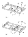
- Fig. 1 is a schematic view of an exercising device 100 according to one embodiment of the present disclosure.
- Fig. 2 is an exploded view of the exercising device 100 as illustrated in Fig. 1 .
- the exercising device 100 includes a base 200, a rail 300, a swinging chair 400, and a swinging unit 500.
- the rail 300 is pivotally disposed at the base 200 by at least one pivoting point 310, wherein a number of the pivoting point 310 is two in the embodiment of Fig. 1 .
- the swinging chair 400 is movably disposed on the rail 300, wherein the swinging chair 400 is moved along the rail 300 linearly.
- the swinging unit 500 is disposed between the rail 300 and the base 200.
- the swinging unit 500 is for changing an angle between the rail 300 and the base 200, precisely, the angle is determined between an extension line I1 of the rail 300 and an extension line I2 of the base 200 (see Figs. 4 and 5 ).
- the position of the swinging chair 400 relative to the position of the base 200 along a horizontal line can be changed.
- a force arm between the pivoting point 310 and a part of the swinging chair 400 is also changed. Therefore, a vibrating amplitude of the part of the swinging chair 400 is changed correspondingly and a swinging strength can be changed too.
- Fig. 3 is an exploded view of a swing driving unit 210 and the swinging unit 500 of the exercising device 100 as illustrated in Fig. 2 .
- the exercising device 100 further includes the swing driving unit 210 disposed at the base 200 for driving the swinging unit 500 to rotate, hence, the rail 300 is linked with the swinging unit 500, and the angle between the rail 300 and the base 200 is changed.
- the swinging unit 500 includes a roller 510, an eccentric block 520 and a wheel 530.
- the eccentric block 520 pushes the rail 300.
- the roller 510 is rotatably disposed on the base 200.
- the wheel 530 and the eccentric block 520 are sleeved on the roller 510 and have no relative rotating motion with respective to the roller 510. In other words, the wheel 530 and the eccentric block 520 are fixed on the roller 510 and rotate with the roller 510 simultaneously.
- the swing driving unit 210 includes a motor 211, a belt 213, a pulley 212, a motor wheel 215 and a motor belt 214.
- the motor wheel 215 is disposed at a shaft of the motor 211
- the motor belt 214 is for connecting the motor wheel 215 to the pulley 212
- the belt 213 is for connecting the pulley 212 to the wheel 530.
- the motor 211 drives the motor wheel 215 and the motor belt 214 to rotate, thus the pulley 212 will be rotated simultaneously, i.e., the pulley 212 is driven by the motor 211 indirectly.
- the pulley 212 When the pulley 212 is driven to rotate, the belt 213, the wheel 530, the roller 510, and the eccentric block 520 will rotate simultaneously, and the rail 300 will be pushed by the eccentric block 520.
- the pulley 212 can be directly disposed at the shaft of the motor 211, and the motor wheel 215 and the motor belt 214 can be omitted in other embodiment. The present disclosure will not be limited to the embodiment of Fig. 3 .
- Fig. 4 is a cross-sectional view of one using state of the rail 300 and the base 200 as illustrated in Fig. 1 .
- Fig. 5 is a cross-sectional view of another using state of the rail 300 and the base 200 as illustrated in Fig. 1 .
- the angle a is changed because of the eccentric rotating motion of the eccentric block 520. Because the eccentric block 520 has different radial distances, a vertical distance between the rail 300 and the roller 510 is changed.
- the swing driving unit 210 can only include a motor 211, and the swinging unit 500 can include a roller 510 and an eccentric block 520.
- the motor 211 directly drives the roller 510 to rotate the eccentric block 520.
- the swing driving unit 210 can include a motor 211 and a first gear (not shown) disposed on the shaft of the motor 211.
- the swinging unit 500 includes a roller 510, a second gear (not shown) engaged with the first gear, and an eccentric block 520.
- the first gear driven by the motor 211 is meshed with the second gear so as to rotate the roller 510 and the eccentric block 520.
- Fig. 6 is a schematic view of one using state of the rail 300 as illustrated in Fig. 1 .
- Fig. 7 is a schematic view of another using state of the rail 300 as illustrated in Fig. 1 .
- the exercising device 100 further includes a moving unit 320 and a horizontal driving unit 330, and the rail 300 further includes two grooves 340 which are parallel to each other.
- the moving unit 320 includes a body 321, two sliders 322, and a screw hole 323.
- the sliders 322 are connected to the body 321, and the screw hole 323 is disposed at the body 321.
- Each of the sliders 322 is disposed in each of the grooves 340.
- the horizontal driving unit 330 includes a motor 331 and a screw arbor 332.
- the motor 331 is disposed at the rail 300.
- One end of the screw arbor 332 is threadly disposed in the screw hole 323 and the other end of the screw arbor 332 is disposed at the rail 300.
- the screw arbor 332 is driven by the motor 331 to rotate, the position of the screw hole 323 relative to the position of the screw arbor 332 will be changed simultaneously so as to make the moving unit 320 moving horizontally in the rail 300.
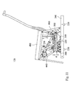
- Fig. 8 is a side view of one mode of the exercising device 100 as illustrated in Fig. 1 .
- Fig. 9 is a side view of another mode of the exercising device 100 as illustrated in Fig. 8 .
- the swinging chair 400 is connected to the moving unit 320, and includes a seat portion 420, a back portion 410, a leg portion 430, and an open-close driving unit 440.
- the back portion 410 is pivotally disposed at the seat portion 420 by two pivoting points 411
- the leg portion 430 is pivotally disposed at the seat portion 420 by two pivoting points 412.
- the open-close driving unit 440 includes a motor 441, an actuator 442, and a linking rod assembly 443.
- One end of the actuator is pivotally disposed at the seat portion 420 and the other end of the actuator 442 is pivotally disposed at the back portion 410. Therefore, when the motor 441 drives the actuator 442 to expand or shrink, the seat portion 420, the linking rod assembly 443, and the leg portion 430 will be acted simultaneously to change an angle b between the back portion 410 and the seat portion 420 or an angle c between the seat portion 420 and the leg portion 430 so as to change the mode of the swinging chair 400.
- a posture of a human can be changed from a lying posture to a sitting posture or from a sitting posture to a lying posture.
- the structure of the open-close driving unit 440 mentioned before is a sampling example and other driving structures can be adapted in other embodiments.
- Fig. 10 is a side view of an exercising device 110 according to another embodiment of the present disclosure.
- the exercising device 110 includes a base 200, a rail 300, a swinging bed 700, a swinging unit 500 and a swing driving unit 210 for swinging the rail 300.
- the rail 300 is pivotally disposed at the base 200.
- the exercising device 110 further includes a moving unit 320 and a horizontal driving unit 330.
- the moving unit 320 is connected to the swinging bed 700, and is driven by the horizontal driving unit 330 to move horizontally in the rail 300. Therefore, the horizontal distance between the moving unit 320 and the pivoting point 310 will be changed.
- the mode of the swinging bed 700 can be changed corresponding to a human body (not shown).
- the structures and relationships of the swinging unit 500, the swing driving unit 210, the rail 300, the horizontal driving unit 330, and the moving unit 320 are similar to aforementioned structures of Fig.1 to Fig. 9 .
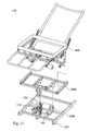
- Fig. 11 is a side view of an exercising device 120 according to yet another embodiment of the present disclosure.
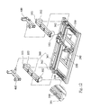
- Fig. 12 is an exploded view of the rail 300 as illustrated in Fig. 11 .
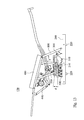
- Fig. 13 is a side view of one mode of the exercising device 120 as illustrated in Fig. 11 .
- the exercising device 120 includes a base 200, a swinging chair 400, two supporting sticks 800, a swinging unit 500, a swing driving unit 210 for swinging the rail 300, and a moving unit 360.
- the rail 300 is pivotally disposed at the base 200 by the pivoting point 310, and includes two grooves 350 and two pad portions 351. Each groove 350 has an opening facing toward the swinging chair 400.
- Each pad portion 351 formed a plank shape is disposed at each groove 350, and is abutted against each wall of each groove 350.
- the moving unit 360 includes a body 361 and two sliders 362.
- the sliders 362 are pivotally connected to the swinging chair 400.
- Each slider 362 is disposed in each groove 350 and can be moved linearly along each groove 350.
- the rail 300 further includes two fixing boards 353 and four fixing blocks 352 which are higher than a depth of the groove 350. Two of the fixing blocks 352 are disposed in two ends of one groove 350, and the other two of the fixing blocks 352 are disposed in two end of the other groove 350.
- the fixing board 353 is connected to the groove 350 via the fixing blocks 352 so that the slider 362 is limitedly positioned between the groove 350 and the fixing board 353.
- the slider 362 is driven by the horizontal driving unit 330 to move along the groove 350, and a moving distance of the slider 362 is limited by the two fixing blocks 352.
- the fixing board 353 is used to prevent the slider 362 separating from the groove 350 during the exercising process.
- the pad portion 351 is used to decrease the noise from the slider 362 during the sliding motion and thus an unwell feeling of a human can be prevented.
- the pad portions 351 are sound absorbing cottons.
- the exercising device 120 further includes a plurality of base pads 220.
- the base pads 220 are disposed under the base 200 for decreasing the vibration effect between the base 200 and a surface where the exercising device 120 is positioned.
- the swinging chair 400 is driven by the horizontal driving unit 330 to move horizontally in the rail 300 so as to change a horizontal distance between the moving unit 360 and the pivoting point 310.
- the mode of the swinging chair 400 can be changed corresponding to a human body via the open-close driving unit 440. Therefore, an angle d between the swinging chair 400 and the rail 300, an angle e between the swinging chair 400 and the supporting stick 800, and/or an angle f between the supporting stick 800 and the base 200 will be changed to make the mode of the swinging chair 400 changing more smoothly.
- the open-close driving unit 440 By controlling the open-close driving unit 440 to change each of the angles, the variation of the swinging amplitude for different human part at different position will increase.
- the structures of the swinging unit 500, the swing driving unit 210, the open-close driving unit 440, the swinging chair 400 and the horizontal driving unit 330 are similar to the aforementioned structures of Fig.1 to Fig. 9 , and there is no need to describe the details.
- Fig. 14 is an exploded view of an exercising device 150 according to yet another embodiment of the present disclosure.
- exercising device 150 includes a base 200b, a rail 300b, a swinging chair 400, a swinging unit 500, an elastic unit 930, a swing driving unit 210 and a plurality of base pads 220.
- the structures of the swinging chair 400, the swinging unit 500 and the swing driving unit 210 are similar to the structures of the embodiment shown in Figs 1 to 9
- the structure of the base pad 220 is similar to the embodiment shown in Figs 11 to 13 , and there is no need to describe in detail.
- the elastic unit 930 is disposed between the base 200b and the rail 300b, and can be deformed to reduce an impulse caused by the rail 300b.
- Fig. 15A is a cross-sectional view of one using state of the rail 300b, the base 200b and the elastic unit 930 as illustrated in Fig. 14
- Fig. 15B is a cross-sectional view of another using state of the rail 300b, the base 200b and the elastic unit 930 as illustrated in Fig. 14 .
- a swinging motion of rail 300b is caused by the swinging unit 500, and a distance between the rail 300b and the base 200b is changed accordingly.
- the elastic unit 930 is deformed by the swinging motion of the rail 300b.
- the rail 300b swings from the highest point toward the lowest point, the gravity and the inertia force of the eccentric block result in producing an impetuous impulse toward a ground where the exercising device 150 (see Fig. 15 ) is disposed.
- the rail 300b and the swinging chair 400 cannot swing smoothly because of the impulse, and a user will feel unwell.
- the elastic unit 930 Between disposing the elastic unit 930 between the rail 300b and the base 200b, the impulse can be absorbed by the elastic unit 930, and a user will feel more comfortable when using the exercising device 150.
- the elastic unit 930 is comprised by the rail 300b in Fig. 15A while extended by the rail 300b in Fig. 15B .
- the elastic unit 930 can only be comprised but not be extended, and keeps an original height while the rail 300b is at the highest position.
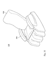
- Fig. 16 is a schematic view of an exercising device 130 according to yet another embodiment of the present disclosure.
- the exercising device 130 further includes two armrests 910 and a chair cover 920.
- the user will feel more comfortable when using the exercising device 130.
- each of the exercising devices 120, the exercising device 130, and the exercising device 150 includes the swinging chair 400, and the swinging chair 400 can be replaced by a swinging bed in other embodiments.
- the swinging speed of the swing driving unit will affect the swinging status of the exercising device.
- the swinging unit swings eccentrically to drive the exercising device swinging simultaneously.
- the exercising device will swing faster and the user will feel the body shaking up and down with small amplitude and higher speed.
- the exercising device will swing slower and the user will feel the body swinging forward and backward.
- the swinging motion is smooth and the body swings in a circle. Further with the function of linear motion, the exercising device can be at different position and can have different swing speed so as to bring a different feeling to users. Thus the user can choose a love way to swing.
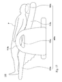
- Fig. 17 is a side view showing one using status of an exercising device 140 according to yet another embodiment of the present disclosure.
- the swinging chair 400a includes a back portion 410a, a seat portion 420a, a leg portion 430a, and a pillow 460a.
- the swinging chair 400a is in a mode for a human to lying.
- the pillow 460a disposed on the back portion 410a is for a user P to lean his or her head on.
- the pillow 460a is disposed to confirm the ergonomic effect and increases the comfortable feeling of user P.
- the pillow 460a can help to fix the position of the head of user p and prevent the head shaking too much during the swinging process.
- the pillow 460 has a shock absorbing function.
- the swinging chair 400a further includes two armrests 910a disposed at two sides of the seat portion 420a, respectively.
- the hands and the legs When the user P is lying, his or her hands will be put on the armrest 910a, and the hands and the legs will be at a higher position than his or her heart. Because the blood is concentrated on the hands and the legs for a sitting posture and a standing posture, the blood hardly returns to the heart. Therefore, the positions of the hands and the legs are designed to be higher than the position of the heart, and the blood returns to the heart from the hands and the legs to increase the blood circulating by the assistance of the swinging function of the exercising device 140.
- the back portion 410a can include a plurality of airbags (not shown) and a plurality of massagers (not shown). Through the inflation and deflation motion of the airbags, and the swinging and moving motion of the massagers, a massage effect on back can be achieved.
- the seat portion 420a can also include a plurality of airbags so as users can enjoy the massage effect for leg and hip. The inflation and deflation motion of the aforementioned airbags can be acted simultaneously or non-simultaneously and thus the massage effect becomes diversifying.
- Fig. 18 is a flow diagram of an operating method of the exercising device 100 as illustrated in Fig. 1 according to yet another embodiment of the present disclosure.
- the operating method 600 of the exercising device 100 includes a linear moving step 610 and a swinging step 630.
- the linear moving step 610 includes providing a rail 300 pivotally disposed at a base 200 by two pivoting points 310, moving the swinging bed 700 or the swinging chair 400 movably positioned on the rail 300, and providing a horizontal driving unit 330 to drive the swinging bed 700 or the swinging chair 400 moving in the rail 300 linearly.
- the swinging step 630 includes providing a swing driving unit 210 for driving a swinging unit 500 to change an angle a between the rail 300 and the base 200 so that the rail 300 moves along a swinging path reciprocatedly.
- the linear moving step 610 provides the linear movement of the swinging bed 700 or the swinging chair 400 first, and then the swinging step 630 vibrates the rail 300 to swing the swinging bed 700 or the swinging chair 400.
- the operating method can further include an open-close step 620.
- the open-close step 620 provides an open-close driving unit 440 to change a mode of the exercising device 100 corresponding to a human.
- the linear moving step 610 is the first step
- the open-close step 620 is the second step
- the swinging step 630 is the final step.
- the sequence of the linear moving step 610 and the open-close step 620 can be changed.
- the open-close step 620 becomes the first step
- the linear moving step 610 becomes the second step
- the swinging step 630 is remained to be the final step.
- the open-close step 620 and the linear moving step 610 can be acted simultaneously and the swing step can be acted soon after. Of cause, all the steps can be acted simultaneously.
- the present disclosure has the following advantages.
- the horizontal position of the swinging chair or the swinging bed can be changed according to the demand of the user.
- the mode of the exercising device can be changed corresponding to a human body so that the user can choose different exercising posture, like sitting posture or lying posture.
- the swinging level and swinging strength for different part of the human body can be changed according to the horizontal position of the exercising device.
- the horizontal position of the swinging bed or the swinging chair can be changed, and the force arm between the pivoting point and the part of the human body will be changed together.
- the horizontal distance between the vertical line of the head and the pivoting point becomes short and thus the force arm becomes short too. Therefore, the swinging amplitude of the head is small and an unwell feeling from head shaking can be reduced.
- the swinging amplitude of other part of the human body is proportional to the force arm, and an exercising effect of other part of the human body can also be achieved.
- the changing of the horizontal position of the swinging bed or the swinging chair will result in changing the corresponding vibrating part of the human body. Choices of a user will increase.
- the exercising device further includes a supporting stick for pivotally connecting to the rail and the swinging chair
- the angle between the rail and the swinging chair, the angle between the supporting stick and the swinging chair, and/or the angle between the supporting stick and the base can be driven to change.
- the swinging amplitude corresponding to the different part of the swinging chair becomes more diversified with the structure of multi-pivoting points, and the types of different swinging motion will be increased.
- the swinging motion can be an up-and-down motion or a circular swinging motion.
- the smoothness of the open-close operation or the linearly moving operation can be increased with the structure and thus the comfortable feelings of users will also be improved.
- the swinging bed or the swinging chair further includes the supporting stick
- the open-closed operation for changing the mode or the swinging bed or swinging chair becomes smoother.
- the structure is stronger during the swinging process with the supporting of the supporting stick.
- the angles of the seat portion can also be changed so that the swinging motion becomes more diversified.
- the sound making by the horizontal linear moving motion of the exercising device can be decreased via the pad portion which is disposed in the groove of the rail, and thus an operating noise can be prevented. Besides, a dimensional tolerance of the groove and the slider can be made larger if the pad portion is disposed in the groove. Therefore, a manufacturing cost as well as difficulties of manufacturing process can be reduced.
- the mode of the exercising chair can be changed via the open-close structure of the exercising device and the operating convenience can be improved.
- the different of the swinging speed of the swinging unit makes the user feeling different swinging motion.
- the swinging speed is high, the swinging amplitude of the human body is small, and the user will feel swing up and down with whole body shaking.
- the swinging speed is small, the swinging amplitude of the human body is large, and the user will feel swing backward and forward with the body swinging circularly. Therefore, the exercising device can provide different exercising effect.
Landscapes
- Health & Medical Sciences (AREA)
- General Health & Medical Sciences (AREA)
- Physical Education & Sports Medicine (AREA)
- Life Sciences & Earth Sciences (AREA)
- Public Health (AREA)
- Veterinary Medicine (AREA)
- Epidemiology (AREA)
- Pain & Pain Management (AREA)
- Rehabilitation Therapy (AREA)
- Animal Behavior & Ethology (AREA)
- Mechanical Engineering (AREA)
- Engineering & Computer Science (AREA)
- Biophysics (AREA)
- Orthopedic Medicine & Surgery (AREA)
- Percussion Or Vibration Massage (AREA)
- Cardiology (AREA)
- Vascular Medicine (AREA)
- Physics & Mathematics (AREA)
- Electromagnetism (AREA)
- Rehabilitation Tools (AREA)
- Massaging Devices (AREA)
- Chairs Characterized By Structure (AREA)
Applications Claiming Priority (2)
| Application Number | Priority Date | Filing Date | Title |
|---|---|---|---|
| TW104105372A TWI598133B (zh) | 2015-02-16 | 2015-02-16 | 晃擺運動器材及其調整方法 |
| TW104129031A TWI572396B (zh) | 2015-09-02 | 2015-09-02 | 晃擺運動器材 |
Publications (3)
| Publication Number | Publication Date |
|---|---|
| EP3056183A2 true EP3056183A2 (de) | 2016-08-17 |
| EP3056183A3 EP3056183A3 (de) | 2016-11-09 |
| EP3056183B1 EP3056183B1 (de) | 2021-05-19 |
Family
ID=54478628
Family Applications (1)
| Application Number | Title | Priority Date | Filing Date |
|---|---|---|---|
| EP15193551.7A Active EP3056183B1 (de) | 2015-02-16 | 2015-11-06 | Übungsvorrichtung und betriebsverfahren dafür |
Country Status (4)
| Country | Link |
|---|---|
| US (1) | US10500434B2 (de) |
| EP (1) | EP3056183B1 (de) |
| JP (1) | JP6250615B2 (de) |
| KR (1) | KR101758200B1 (de) |
Families Citing this family (4)
| Publication number | Priority date | Publication date | Assignee | Title |
|---|---|---|---|---|
| WO2019140454A1 (en) * | 2018-01-12 | 2019-07-18 | Dynasplint System, Inc. | Knee replacement therapy unit |
| CN113693878A (zh) * | 2021-08-17 | 2021-11-26 | 迈族智能科技(上海)有限公司 | 一种垂直震幅辅助平台 |
| KR102755262B1 (ko) * | 2021-09-17 | 2025-01-14 | 오상훈 | 전신진동운동 마사지장치 |
| CN115317306B (zh) * | 2022-08-10 | 2026-02-06 | 瑞多(上海)智能科技有限公司 | 按摩椅 |
Family Cites Families (67)
| Publication number | Priority date | Publication date | Assignee | Title |
|---|---|---|---|---|
| US2226861A (en) * | 1939-11-29 | 1940-12-31 | American Seating Co | Chair |
| US2696207A (en) * | 1951-10-29 | 1954-12-07 | Edward W Bushnell | Rocking hospital bed |
| US2714922A (en) * | 1952-10-17 | 1955-08-09 | Joseph L Mckibban | Adjustable reclining chair |
| US2808828A (en) * | 1955-01-10 | 1957-10-08 | Rubin Joseph Salem | Rocking bed |
| US2874689A (en) * | 1957-10-02 | 1959-02-24 | Jules W Gavelek | Body exercising device |
| US3381997A (en) * | 1966-09-06 | 1968-05-07 | Edward E. Fritz | Adjustable chair |
| US3873152A (en) * | 1974-01-09 | 1975-03-25 | John Garas | Adjustable orthopedic lounger |
| US4074371A (en) * | 1976-08-04 | 1978-02-21 | Christian Services, Inc. | Motorized hide-a-bed actuating mechanism |
| US4226468A (en) * | 1978-03-13 | 1980-10-07 | Pontiac Furniture Industries, Inc. | Wall-clearing recliner |
| US4386803A (en) * | 1981-11-05 | 1983-06-07 | Gilderbloom Clarence W | Motorized reclining chair |
| US4563784A (en) * | 1984-08-17 | 1986-01-14 | Fred Shrock | Power actuated seat-bed assembly |
| US4678231A (en) * | 1985-09-13 | 1987-07-07 | Contour Chair-Lounge Co., Inc. | Adjustable chair |
| JPS6278144U (de) | 1985-11-01 | 1987-05-19 | ||
| US4696512A (en) * | 1986-03-06 | 1987-09-29 | Berkline Corporation | Motorized recliner chair with release mechanism |
| DE3638359A1 (de) | 1986-11-10 | 1988-09-29 | Norbert Schipke | Vorrichtung zur vibrationstherapie |
| DK0517934T3 (da) * | 1991-06-10 | 1995-08-21 | Siemens Ag | Tandlæge-patientstol med svingbart ryglæn |
| US5992931A (en) * | 1991-10-11 | 1999-11-30 | La-Z-Boy Incorporated | Modular power reclining chair |
| US5372505A (en) * | 1992-01-24 | 1994-12-13 | Smith; David | Vehicle simulator |
| US5556163A (en) * | 1994-08-17 | 1996-09-17 | Eac Corporation | Automatically adjustable office and task chairs |
| US5790997A (en) * | 1995-08-04 | 1998-08-11 | Hill-Rom Inc. | Table/chair egress device |
| DE19801524B4 (de) | 1998-01-16 | 2005-12-15 | himolla Polstermöbel GmbH | Sitz- und/oder Liegemöbel |
| DE19901076A1 (de) * | 1999-01-14 | 2000-07-20 | Moll Sys & Funktions Moebel | Stuhl |
| US6158808A (en) * | 1999-03-05 | 2000-12-12 | Margolis; Meg | Fully adjustable lounge chair |
| EP1754462B1 (de) * | 1999-12-29 | 2016-07-13 | Hill-Rom Services, Inc. | Patientenliege mit Aktuatorbetätigungsglied |
| US20020121803A1 (en) * | 2001-03-02 | 2002-09-05 | Schooler Paul T. | Ten way power adjustable seat |
| US6481796B1 (en) * | 2001-05-03 | 2002-11-19 | Hsin Hao Health Materials Co., Ltd. | Chair having a reclining structure |
| US20030055365A1 (en) * | 2001-09-20 | 2003-03-20 | Hazard Rowland G. | System for providing lumbar motion and support |
| KR200331077Y1 (ko) | 2003-05-16 | 2003-10-23 | 박영고 | 삼차원 자동 진동침대 |
| DE20313891U1 (de) * | 2003-09-08 | 2004-02-26 | Fiedler, Hans | Verwandelbares Polstermöbel mit Sessel- und Liegefunktion |
| US20060238007A1 (en) * | 2005-04-26 | 2006-10-26 | Lin Chang C | Chair with aid in lying back and getting up |
| TWI278333B (en) | 2006-03-03 | 2007-04-11 | B Green Technology Co Ltd | Equilibrium training exercise apparatus concurrently possessing slide and vibration and exercise method thereof |
| TWI278332B (en) * | 2006-03-21 | 2007-04-11 | B Green Technology Co Ltd | Whole body vibration training apparatus capable of linearly changing vibration range |
| US20070259758A1 (en) * | 2006-05-02 | 2007-11-08 | Cian-Chang Zeng | Swaying fitness equipment structure |
| CN2925531Y (zh) | 2006-05-22 | 2007-07-25 | 安得士株式会社 | 健身器材 |
| US20070299373A1 (en) * | 2006-06-27 | 2007-12-27 | Michael Lin | Body vibrating mechanism |
| US7862489B2 (en) | 2006-07-17 | 2011-01-04 | Studio Moderna Sa | Multipurpose exercise system |
| CN201091670Y (zh) | 2007-08-24 | 2008-07-30 | 叶东龙 | 马达带动水平振动摇摆机构 |
| TWM337370U (en) * | 2008-03-07 | 2008-08-01 | Chiu-Hsiang Lo | Massage chair with a chair angle adjusting mechanism for the chair rack |
| US20090247914A1 (en) * | 2008-04-01 | 2009-10-01 | Kuei-Hsien Shen | Vibration machine for physical fitness |
| US7722114B2 (en) * | 2008-04-11 | 2010-05-25 | Jobri Llc | Zero gravity wall hugger recliner |
| DE202008015674U1 (de) | 2008-11-26 | 2009-03-26 | Schiessl, Hans | Vorrichtung zur Erzeugung einer Trainingskraft für einen Benutzer eines Trainingsgeräts |
| TWM361360U (en) | 2008-12-31 | 2009-07-21 | Chang Yow Technologies Internat Co Ltd | Swing exercise machine |
| TW201032861A (en) | 2009-03-11 | 2010-09-16 | B Green Technology Co Ltd | Oscillation exercise platform |
| CN201431738Y (zh) * | 2009-03-11 | 2010-03-31 | 明根股份有限公司 | 摆动运动平台 |
| KR100942968B1 (ko) | 2009-07-31 | 2010-02-26 | 주식회사 카이스트종합메디칼 | 재활치료용 운동기구 |
| AU2011229137B2 (en) * | 2010-03-15 | 2015-10-29 | Hypervibe Pty Ltd | Vibration apparatus |
| DE102010050302B4 (de) | 2010-11-03 | 2012-05-31 | Ralf Winter | Zwangsführung eines Kreuzgelenkes oder Kugelgelenkes für ein Spielgerät |
| SG2014005904A (en) | 2011-02-18 | 2014-03-28 | Daito Electric Machine Ind | Chair-type massage apparatus |
| JP5800523B2 (ja) | 2011-02-18 | 2015-10-28 | 大東電機工業株式会社 | 椅子型マッサージ機 |
| WO2012170863A2 (en) * | 2011-06-09 | 2012-12-13 | Haworth, Inc. | Forward sliding reclining chair |
| CN102599747A (zh) | 2012-03-19 | 2012-07-25 | 安徽久工科技实业有限责任公司 | 一种自动休闲摇椅 |
| DE102012105717A1 (de) * | 2012-06-28 | 2014-01-02 | Dewertokin Gmbh | Elektromotorischer Möbelantrieb |
| DE102012212121A1 (de) | 2012-07-11 | 2014-01-16 | Eb-Invent Gmbh | Sitzvorrichtung |
| DE202012102949U1 (de) * | 2012-08-06 | 2012-09-03 | Ciar S.P.A. | Antriebssystem mit einem Linearaktuator sowie Möbelstück mit einem solchen Antriebssystem |
| US9113712B2 (en) * | 2012-09-12 | 2015-08-25 | Klaussner Furniture Industries, Inc. | Method and system for converting a recliner from manual actuation to powered actuation |
| KR101411628B1 (ko) | 2012-10-19 | 2014-06-24 | 부산대학교 산학협력단 | 3축 인체 진동기 |
| CN203123445U (zh) | 2012-10-23 | 2013-08-14 | 朱振纲 | 一种摇摆器 |
| ITRM20120596A1 (it) | 2012-11-27 | 2014-05-28 | Bios Project Srl | Macchina per massaggi con letto inclinabile provvisto di seduta |
| RU2015135584A (ru) * | 2013-01-23 | 2017-03-02 | Зодиак Ситс Франс | Кинематическое устройство компактного сиденья |
| CA2902891C (en) * | 2013-04-08 | 2017-08-22 | B/E Aerospace, Inc. | Aircraft seat employing dual actuators for seat translation and seat recline |
| US9022473B2 (en) * | 2013-05-02 | 2015-05-05 | L&P Property Management Company | Rocker recliner mechanism with changeable features |
| CN203291182U (zh) | 2013-06-21 | 2013-11-20 | 孙景玉 | 多功能保健椅 |
| CN203370074U (zh) | 2013-07-08 | 2014-01-01 | 吴景华 | 可调节小腿架的按摩椅架 |
| CA2975418C (en) * | 2014-01-29 | 2018-10-23 | Billy Joe GRIGGS, Jr. | Motor assembly for reclining furniture |
| CN203988893U (zh) | 2014-07-15 | 2014-12-10 | 光昱金属有限公司 | 震动摇摆机 |
| CN204709707U (zh) | 2015-02-16 | 2015-10-21 | 光昱金属有限公司 | 晃摆运动器材 |
| US20170128320A1 (en) * | 2015-11-10 | 2017-05-11 | Hsin Hao Health Materials Co., Ltd. | Massage chair |
-
2015
- 2015-10-06 US US14/875,706 patent/US10500434B2/en active Active
- 2015-11-03 KR KR1020150154066A patent/KR101758200B1/ko active Active
- 2015-11-06 EP EP15193551.7A patent/EP3056183B1/de active Active
- 2015-11-20 JP JP2015227474A patent/JP6250615B2/ja active Active
Non-Patent Citations (1)
| Title |
|---|
| None |
Also Published As
| Publication number | Publication date |
|---|---|
| JP2016150247A (ja) | 2016-08-22 |
| KR101758200B1 (ko) | 2017-07-26 |
| JP6250615B2 (ja) | 2017-12-20 |
| EP3056183A3 (de) | 2016-11-09 |
| KR20160100804A (ko) | 2016-08-24 |
| US20160236030A1 (en) | 2016-08-18 |
| US10500434B2 (en) | 2019-12-10 |
| EP3056183B1 (de) | 2021-05-19 |
Similar Documents
| Publication | Publication Date | Title |
|---|---|---|
| JP3764471B1 (ja) | バランス健康機 | |
| US6964614B1 (en) | Riding device | |
| US7201707B1 (en) | Elliptical exercise machine with adjustable stride length | |
| US10500434B2 (en) | Exercising device and operating method thereof | |
| CN204840147U (zh) | 一种上下肢康复椅 | |
| TWI401103B (zh) | Sports device | |
| CN102048634A (zh) | 按摩装置 | |
| CN204709707U (zh) | 晃摆运动器材 | |
| CA2976733C (en) | Exercising device and operating method thereof | |
| KR100977046B1 (ko) | 승마형 운동기구 | |
| KR20090069793A (ko) | 균형감각 향상 운동기구 | |
| CN105983207B (zh) | 晃摆运动器材及其调整方法 | |
| CN101112649A (zh) | 可调整踏板轨迹斜度的椭圆运动机 | |
| TWI598133B (zh) | 晃擺運動器材及其調整方法 | |
| CN112168602A (zh) | 律动运动与起身辅助装置 | |
| CN211157081U (zh) | 一种多功能老年健身摇篮床 | |
| TW201336552A (zh) | 座式踏步機 | |
| CN206621746U (zh) | 平衡健身板 | |
| CN106474664A (zh) | 晃摆运动器材 | |
| CN1331454C (zh) | 一种保健椅 | |
| JP3110244U (ja) | ペダル漕ぎ健康器具 | |
| CN223233222U (zh) | 平衡触感训练器 | |
| CN200942267Y (zh) | 具弹性缓冲及摇摆动作路径的运动复健器具 | |
| TWI572396B (zh) | 晃擺運動器材 | |
| TWM517624U (zh) | 晃擺運動器材及其調整方法 |
Legal Events
| Date | Code | Title | Description |
|---|---|---|---|
| PUAI | Public reference made under article 153(3) epc to a published international application that has entered the european phase |
Free format text: ORIGINAL CODE: 0009012 |
|
| 17P | Request for examination filed |
Effective date: 20160120 |
|
| AK | Designated contracting states |
Kind code of ref document: A2 Designated state(s): AL AT BE BG CH CY CZ DE DK EE ES FI FR GB GR HR HU IE IS IT LI LT LU LV MC MK MT NL NO PL PT RO RS SE SI SK SM TR |
|
| AX | Request for extension of the european patent |
Extension state: BA ME |
|
| PUAL | Search report despatched |
Free format text: ORIGINAL CODE: 0009013 |
|
| AK | Designated contracting states |
Kind code of ref document: A3 Designated state(s): AL AT BE BG CH CY CZ DE DK EE ES FI FR GB GR HR HU IE IS IT LI LT LU LV MC MK MT NL NO PL PT RO RS SE SI SK SM TR |
|
| AX | Request for extension of the european patent |
Extension state: BA ME |
|
| RIC1 | Information provided on ipc code assigned before grant |
Ipc: A61H 1/00 20060101ALI20160930BHEP Ipc: A61H 23/00 20060101AFI20160930BHEP Ipc: A47C 3/025 20060101ALI20160930BHEP Ipc: A47C 3/02 20060101ALI20160930BHEP Ipc: A63B 21/00 20060101ALI20160930BHEP |
|
| STAA | Information on the status of an ep patent application or granted ep patent |
Free format text: STATUS: EXAMINATION IS IN PROGRESS |
|
| 17Q | First examination report despatched |
Effective date: 20190320 |
|
| GRAP | Despatch of communication of intention to grant a patent |
Free format text: ORIGINAL CODE: EPIDOSNIGR1 |
|
| STAA | Information on the status of an ep patent application or granted ep patent |
Free format text: STATUS: GRANT OF PATENT IS INTENDED |
|
| INTG | Intention to grant announced |
Effective date: 20201211 |
|
| GRAS | Grant fee paid |
Free format text: ORIGINAL CODE: EPIDOSNIGR3 |
|
| GRAA | (expected) grant |
Free format text: ORIGINAL CODE: 0009210 |
|
| STAA | Information on the status of an ep patent application or granted ep patent |
Free format text: STATUS: THE PATENT HAS BEEN GRANTED |
|
| AK | Designated contracting states |
Kind code of ref document: B1 Designated state(s): AL AT BE BG CH CY CZ DE DK EE ES FI FR GB GR HR HU IE IS IT LI LT LU LV MC MK MT NL NO PL PT RO RS SE SI SK SM TR |
|
| REG | Reference to a national code |
Ref country code: GB Ref legal event code: FG4D |
|
| REG | Reference to a national code |
Ref country code: CH Ref legal event code: EP |
|
| REG | Reference to a national code |
Ref country code: DE Ref legal event code: R096 Ref document number: 602015069376 Country of ref document: DE |
|
| REG | Reference to a national code |
Ref country code: AT Ref legal event code: REF Ref document number: 1393297 Country of ref document: AT Kind code of ref document: T Effective date: 20210615 |
|
| REG | Reference to a national code |
Ref country code: IE Ref legal event code: FG4D |
|
| REG | Reference to a national code |
Ref country code: LT Ref legal event code: MG9D |
|
| REG | Reference to a national code |
Ref country code: AT Ref legal event code: MK05 Ref document number: 1393297 Country of ref document: AT Kind code of ref document: T Effective date: 20210519 |
|
| REG | Reference to a national code |
Ref country code: NL Ref legal event code: MP Effective date: 20210519 |
|
| PG25 | Lapsed in a contracting state [announced via postgrant information from national office to epo] |
Ref country code: LT Free format text: LAPSE BECAUSE OF FAILURE TO SUBMIT A TRANSLATION OF THE DESCRIPTION OR TO PAY THE FEE WITHIN THE PRESCRIBED TIME-LIMIT Effective date: 20210519 Ref country code: FI Free format text: LAPSE BECAUSE OF FAILURE TO SUBMIT A TRANSLATION OF THE DESCRIPTION OR TO PAY THE FEE WITHIN THE PRESCRIBED TIME-LIMIT Effective date: 20210519 Ref country code: BG Free format text: LAPSE BECAUSE OF FAILURE TO SUBMIT A TRANSLATION OF THE DESCRIPTION OR TO PAY THE FEE WITHIN THE PRESCRIBED TIME-LIMIT Effective date: 20210819 Ref country code: AT Free format text: LAPSE BECAUSE OF FAILURE TO SUBMIT A TRANSLATION OF THE DESCRIPTION OR TO PAY THE FEE WITHIN THE PRESCRIBED TIME-LIMIT Effective date: 20210519 Ref country code: HR Free format text: LAPSE BECAUSE OF FAILURE TO SUBMIT A TRANSLATION OF THE DESCRIPTION OR TO PAY THE FEE WITHIN THE PRESCRIBED TIME-LIMIT Effective date: 20210519 |
|
| PG25 | Lapsed in a contracting state [announced via postgrant information from national office to epo] |
Ref country code: LV Free format text: LAPSE BECAUSE OF FAILURE TO SUBMIT A TRANSLATION OF THE DESCRIPTION OR TO PAY THE FEE WITHIN THE PRESCRIBED TIME-LIMIT Effective date: 20210519 Ref country code: IS Free format text: LAPSE BECAUSE OF FAILURE TO SUBMIT A TRANSLATION OF THE DESCRIPTION OR TO PAY THE FEE WITHIN THE PRESCRIBED TIME-LIMIT Effective date: 20210919 Ref country code: GR Free format text: LAPSE BECAUSE OF FAILURE TO SUBMIT A TRANSLATION OF THE DESCRIPTION OR TO PAY THE FEE WITHIN THE PRESCRIBED TIME-LIMIT Effective date: 20210820 Ref country code: SE Free format text: LAPSE BECAUSE OF FAILURE TO SUBMIT A TRANSLATION OF THE DESCRIPTION OR TO PAY THE FEE WITHIN THE PRESCRIBED TIME-LIMIT Effective date: 20210519 Ref country code: RS Free format text: LAPSE BECAUSE OF FAILURE TO SUBMIT A TRANSLATION OF THE DESCRIPTION OR TO PAY THE FEE WITHIN THE PRESCRIBED TIME-LIMIT Effective date: 20210519 Ref country code: NO Free format text: LAPSE BECAUSE OF FAILURE TO SUBMIT A TRANSLATION OF THE DESCRIPTION OR TO PAY THE FEE WITHIN THE PRESCRIBED TIME-LIMIT Effective date: 20210819 Ref country code: PL Free format text: LAPSE BECAUSE OF FAILURE TO SUBMIT A TRANSLATION OF THE DESCRIPTION OR TO PAY THE FEE WITHIN THE PRESCRIBED TIME-LIMIT Effective date: 20210519 Ref country code: PT Free format text: LAPSE BECAUSE OF FAILURE TO SUBMIT A TRANSLATION OF THE DESCRIPTION OR TO PAY THE FEE WITHIN THE PRESCRIBED TIME-LIMIT Effective date: 20210920 Ref country code: ES Free format text: LAPSE BECAUSE OF FAILURE TO SUBMIT A TRANSLATION OF THE DESCRIPTION OR TO PAY THE FEE WITHIN THE PRESCRIBED TIME-LIMIT Effective date: 20210519 |
|
| PG25 | Lapsed in a contracting state [announced via postgrant information from national office to epo] |
Ref country code: NL Free format text: LAPSE BECAUSE OF FAILURE TO SUBMIT A TRANSLATION OF THE DESCRIPTION OR TO PAY THE FEE WITHIN THE PRESCRIBED TIME-LIMIT Effective date: 20210519 |
|
| PG25 | Lapsed in a contracting state [announced via postgrant information from national office to epo] |
Ref country code: RO Free format text: LAPSE BECAUSE OF FAILURE TO SUBMIT A TRANSLATION OF THE DESCRIPTION OR TO PAY THE FEE WITHIN THE PRESCRIBED TIME-LIMIT Effective date: 20210519 Ref country code: SK Free format text: LAPSE BECAUSE OF FAILURE TO SUBMIT A TRANSLATION OF THE DESCRIPTION OR TO PAY THE FEE WITHIN THE PRESCRIBED TIME-LIMIT Effective date: 20210519 Ref country code: SM Free format text: LAPSE BECAUSE OF FAILURE TO SUBMIT A TRANSLATION OF THE DESCRIPTION OR TO PAY THE FEE WITHIN THE PRESCRIBED TIME-LIMIT Effective date: 20210519 Ref country code: CZ Free format text: LAPSE BECAUSE OF FAILURE TO SUBMIT A TRANSLATION OF THE DESCRIPTION OR TO PAY THE FEE WITHIN THE PRESCRIBED TIME-LIMIT Effective date: 20210519 Ref country code: EE Free format text: LAPSE BECAUSE OF FAILURE TO SUBMIT A TRANSLATION OF THE DESCRIPTION OR TO PAY THE FEE WITHIN THE PRESCRIBED TIME-LIMIT Effective date: 20210519 Ref country code: DK Free format text: LAPSE BECAUSE OF FAILURE TO SUBMIT A TRANSLATION OF THE DESCRIPTION OR TO PAY THE FEE WITHIN THE PRESCRIBED TIME-LIMIT Effective date: 20210519 |
|
| REG | Reference to a national code |
Ref country code: DE Ref legal event code: R097 Ref document number: 602015069376 Country of ref document: DE |
|
| PLBE | No opposition filed within time limit |
Free format text: ORIGINAL CODE: 0009261 |
|
| STAA | Information on the status of an ep patent application or granted ep patent |
Free format text: STATUS: NO OPPOSITION FILED WITHIN TIME LIMIT |
|
| 26N | No opposition filed |
Effective date: 20220222 |
|
| PG25 | Lapsed in a contracting state [announced via postgrant information from national office to epo] |
Ref country code: IS Free format text: LAPSE BECAUSE OF FAILURE TO SUBMIT A TRANSLATION OF THE DESCRIPTION OR TO PAY THE FEE WITHIN THE PRESCRIBED TIME-LIMIT Effective date: 20210919 Ref country code: AL Free format text: LAPSE BECAUSE OF FAILURE TO SUBMIT A TRANSLATION OF THE DESCRIPTION OR TO PAY THE FEE WITHIN THE PRESCRIBED TIME-LIMIT Effective date: 20210519 |
|
| PG25 | Lapsed in a contracting state [announced via postgrant information from national office to epo] |
Ref country code: MC Free format text: LAPSE BECAUSE OF FAILURE TO SUBMIT A TRANSLATION OF THE DESCRIPTION OR TO PAY THE FEE WITHIN THE PRESCRIBED TIME-LIMIT Effective date: 20210519 |
|
| REG | Reference to a national code |
Ref country code: CH Ref legal event code: PL |
|
| PG25 | Lapsed in a contracting state [announced via postgrant information from national office to epo] |
Ref country code: LU Free format text: LAPSE BECAUSE OF NON-PAYMENT OF DUE FEES Effective date: 20211106 Ref country code: IT Free format text: LAPSE BECAUSE OF FAILURE TO SUBMIT A TRANSLATION OF THE DESCRIPTION OR TO PAY THE FEE WITHIN THE PRESCRIBED TIME-LIMIT Effective date: 20210519 Ref country code: BE Free format text: LAPSE BECAUSE OF NON-PAYMENT OF DUE FEES Effective date: 20211130 |
|
| REG | Reference to a national code |
Ref country code: BE Ref legal event code: MM Effective date: 20211130 |
|
| PG25 | Lapsed in a contracting state [announced via postgrant information from national office to epo] |
Ref country code: LI Free format text: LAPSE BECAUSE OF NON-PAYMENT OF DUE FEES Effective date: 20211130 Ref country code: CH Free format text: LAPSE BECAUSE OF NON-PAYMENT OF DUE FEES Effective date: 20211130 |
|
| PG25 | Lapsed in a contracting state [announced via postgrant information from national office to epo] |
Ref country code: IE Free format text: LAPSE BECAUSE OF NON-PAYMENT OF DUE FEES Effective date: 20211106 |
|
| PG25 | Lapsed in a contracting state [announced via postgrant information from national office to epo] |
Ref country code: HU Free format text: LAPSE BECAUSE OF FAILURE TO SUBMIT A TRANSLATION OF THE DESCRIPTION OR TO PAY THE FEE WITHIN THE PRESCRIBED TIME-LIMIT; INVALID AB INITIO Effective date: 20151106 |
|
| PG25 | Lapsed in a contracting state [announced via postgrant information from national office to epo] |
Ref country code: CY Free format text: LAPSE BECAUSE OF FAILURE TO SUBMIT A TRANSLATION OF THE DESCRIPTION OR TO PAY THE FEE WITHIN THE PRESCRIBED TIME-LIMIT Effective date: 20210519 |
|
| PG25 | Lapsed in a contracting state [announced via postgrant information from national office to epo] |
Ref country code: MK Free format text: LAPSE BECAUSE OF FAILURE TO SUBMIT A TRANSLATION OF THE DESCRIPTION OR TO PAY THE FEE WITHIN THE PRESCRIBED TIME-LIMIT Effective date: 20210519 |
|
| PG25 | Lapsed in a contracting state [announced via postgrant information from national office to epo] |
Ref country code: MT Free format text: LAPSE BECAUSE OF FAILURE TO SUBMIT A TRANSLATION OF THE DESCRIPTION OR TO PAY THE FEE WITHIN THE PRESCRIBED TIME-LIMIT Effective date: 20210519 |
|
| PG25 | Lapsed in a contracting state [announced via postgrant information from national office to epo] |
Ref country code: TR Free format text: LAPSE BECAUSE OF FAILURE TO SUBMIT A TRANSLATION OF THE DESCRIPTION OR TO PAY THE FEE WITHIN THE PRESCRIBED TIME-LIMIT Effective date: 20210519 |
|
| PGFP | Annual fee paid to national office [announced via postgrant information from national office to epo] |
Ref country code: DE Payment date: 20251028 Year of fee payment: 11 |
|
| PGFP | Annual fee paid to national office [announced via postgrant information from national office to epo] |
Ref country code: GB Payment date: 20251030 Year of fee payment: 11 |
|
| PGFP | Annual fee paid to national office [announced via postgrant information from national office to epo] |
Ref country code: FR Payment date: 20251110 Year of fee payment: 11 |