EP3056301A1 - Objekt und angepasste kontaktlose stütze die mit einem generativen prozess hergestellt sind - Google Patents
Objekt und angepasste kontaktlose stütze die mit einem generativen prozess hergestellt sind Download PDFInfo
- Publication number
- EP3056301A1 EP3056301A1 EP16155047.0A EP16155047A EP3056301A1 EP 3056301 A1 EP3056301 A1 EP 3056301A1 EP 16155047 A EP16155047 A EP 16155047A EP 3056301 A1 EP3056301 A1 EP 3056301A1
- Authority
- EP
- European Patent Office
- Prior art keywords
- component
- additively manufactured
- contact support
- recited
- edge
- Prior art date
- Legal status (The legal status is an assumption and is not a legal conclusion. Google has not performed a legal analysis and makes no representation as to the accuracy of the status listed.)
- Granted
Links
Images

Classifications
-
- B—PERFORMING OPERATIONS; TRANSPORTING
- B29—WORKING OF PLASTICS; WORKING OF SUBSTANCES IN A PLASTIC STATE IN GENERAL
- B29C—SHAPING OR JOINING OF PLASTICS; SHAPING OF MATERIAL IN A PLASTIC STATE, NOT OTHERWISE PROVIDED FOR; AFTER-TREATMENT OF THE SHAPED PRODUCTS, e.g. REPAIRING
- B29C64/00—Additive manufacturing, i.e. manufacturing of three-dimensional [3D] objects by additive deposition, additive agglomeration or additive layering, e.g. by 3D printing, stereolithography or selective laser sintering
- B29C64/10—Processes of additive manufacturing
- B29C64/141—Processes of additive manufacturing using only solid materials
- B29C64/153—Processes of additive manufacturing using only solid materials using layers of powder being selectively joined, e.g. by selective laser sintering or melting
-
- B—PERFORMING OPERATIONS; TRANSPORTING
- B22—CASTING; POWDER METALLURGY
- B22F—WORKING METALLIC POWDER; MANUFACTURE OF ARTICLES FROM METALLIC POWDER; MAKING METALLIC POWDER; APPARATUS OR DEVICES SPECIALLY ADAPTED FOR METALLIC POWDER
- B22F10/00—Additive manufacturing of workpieces or articles from metallic powder
- B22F10/40—Structures for supporting workpieces or articles during manufacture and removed afterwards
-
- B—PERFORMING OPERATIONS; TRANSPORTING
- B22—CASTING; POWDER METALLURGY
- B22F—WORKING METALLIC POWDER; MANUFACTURE OF ARTICLES FROM METALLIC POWDER; MAKING METALLIC POWDER; APPARATUS OR DEVICES SPECIALLY ADAPTED FOR METALLIC POWDER
- B22F10/00—Additive manufacturing of workpieces or articles from metallic powder
- B22F10/40—Structures for supporting workpieces or articles during manufacture and removed afterwards
- B22F10/47—Structures for supporting workpieces or articles during manufacture and removed afterwards characterised by structural features
-
- B—PERFORMING OPERATIONS; TRANSPORTING
- B22—CASTING; POWDER METALLURGY
- B22F—WORKING METALLIC POWDER; MANUFACTURE OF ARTICLES FROM METALLIC POWDER; MAKING METALLIC POWDER; APPARATUS OR DEVICES SPECIALLY ADAPTED FOR METALLIC POWDER
- B22F12/00—Apparatus or devices specially adapted for additive manufacturing; Auxiliary means for additive manufacturing; Combinations of additive manufacturing apparatus or devices with other processing apparatus or devices
-
- B—PERFORMING OPERATIONS; TRANSPORTING
- B22—CASTING; POWDER METALLURGY
- B22F—WORKING METALLIC POWDER; MANUFACTURE OF ARTICLES FROM METALLIC POWDER; MAKING METALLIC POWDER; APPARATUS OR DEVICES SPECIALLY ADAPTED FOR METALLIC POWDER
- B22F12/00—Apparatus or devices specially adapted for additive manufacturing; Auxiliary means for additive manufacturing; Combinations of additive manufacturing apparatus or devices with other processing apparatus or devices
- B22F12/60—Planarisation devices; Compression devices
- B22F12/67—Blades
-
- B—PERFORMING OPERATIONS; TRANSPORTING
- B29—WORKING OF PLASTICS; WORKING OF SUBSTANCES IN A PLASTIC STATE IN GENERAL
- B29C—SHAPING OR JOINING OF PLASTICS; SHAPING OF MATERIAL IN A PLASTIC STATE, NOT OTHERWISE PROVIDED FOR; AFTER-TREATMENT OF THE SHAPED PRODUCTS, e.g. REPAIRING
- B29C64/00—Additive manufacturing, i.e. manufacturing of three-dimensional [3D] objects by additive deposition, additive agglomeration or additive layering, e.g. by 3D printing, stereolithography or selective laser sintering
- B29C64/10—Processes of additive manufacturing
- B29C64/171—Processes of additive manufacturing specially adapted for manufacturing multiple 3D objects
- B29C64/182—Processes of additive manufacturing specially adapted for manufacturing multiple 3D objects in parallel batches
-
- B—PERFORMING OPERATIONS; TRANSPORTING
- B29—WORKING OF PLASTICS; WORKING OF SUBSTANCES IN A PLASTIC STATE IN GENERAL
- B29C—SHAPING OR JOINING OF PLASTICS; SHAPING OF MATERIAL IN A PLASTIC STATE, NOT OTHERWISE PROVIDED FOR; AFTER-TREATMENT OF THE SHAPED PRODUCTS, e.g. REPAIRING
- B29C64/00—Additive manufacturing, i.e. manufacturing of three-dimensional [3D] objects by additive deposition, additive agglomeration or additive layering, e.g. by 3D printing, stereolithography or selective laser sintering
- B29C64/40—Structures for supporting 3D objects during manufacture and intended to be sacrificed after completion thereof
-
- B—PERFORMING OPERATIONS; TRANSPORTING
- B33—ADDITIVE MANUFACTURING TECHNOLOGY
- B33Y—ADDITIVE MANUFACTURING, i.e. MANUFACTURING OF THREE-DIMENSIONAL [3D] OBJECTS BY ADDITIVE DEPOSITION, ADDITIVE AGGLOMERATION OR ADDITIVE LAYERING, e.g. BY 3D PRINTING, STEREOLITHOGRAPHY OR SELECTIVE LASER SINTERING
- B33Y10/00—Processes of additive manufacturing
-
- B—PERFORMING OPERATIONS; TRANSPORTING
- B33—ADDITIVE MANUFACTURING TECHNOLOGY
- B33Y—ADDITIVE MANUFACTURING, i.e. MANUFACTURING OF THREE-DIMENSIONAL [3D] OBJECTS BY ADDITIVE DEPOSITION, ADDITIVE AGGLOMERATION OR ADDITIVE LAYERING, e.g. BY 3D PRINTING, STEREOLITHOGRAPHY OR SELECTIVE LASER SINTERING
- B33Y80/00—Products made by additive manufacturing
-
- B—PERFORMING OPERATIONS; TRANSPORTING
- B22—CASTING; POWDER METALLURGY
- B22F—WORKING METALLIC POWDER; MANUFACTURE OF ARTICLES FROM METALLIC POWDER; MAKING METALLIC POWDER; APPARATUS OR DEVICES SPECIALLY ADAPTED FOR METALLIC POWDER
- B22F10/00—Additive manufacturing of workpieces or articles from metallic powder
- B22F10/10—Formation of a green body
-
- B—PERFORMING OPERATIONS; TRANSPORTING
- B22—CASTING; POWDER METALLURGY
- B22F—WORKING METALLIC POWDER; MANUFACTURE OF ARTICLES FROM METALLIC POWDER; MAKING METALLIC POWDER; APPARATUS OR DEVICES SPECIALLY ADAPTED FOR METALLIC POWDER
- B22F10/00—Additive manufacturing of workpieces or articles from metallic powder
- B22F10/20—Direct sintering or melting
- B22F10/28—Powder bed fusion, e.g. selective laser melting [SLM] or electron beam melting [EBM]
-
- B—PERFORMING OPERATIONS; TRANSPORTING
- B22—CASTING; POWDER METALLURGY
- B22F—WORKING METALLIC POWDER; MANUFACTURE OF ARTICLES FROM METALLIC POWDER; MAKING METALLIC POWDER; APPARATUS OR DEVICES SPECIALLY ADAPTED FOR METALLIC POWDER
- B22F10/00—Additive manufacturing of workpieces or articles from metallic powder
- B22F10/30—Process control
- B22F10/32—Process control of the atmosphere, e.g. composition or pressure in a building chamber
-
- B—PERFORMING OPERATIONS; TRANSPORTING
- B22—CASTING; POWDER METALLURGY
- B22F—WORKING METALLIC POWDER; MANUFACTURE OF ARTICLES FROM METALLIC POWDER; MAKING METALLIC POWDER; APPARATUS OR DEVICES SPECIALLY ADAPTED FOR METALLIC POWDER
- B22F12/00—Apparatus or devices specially adapted for additive manufacturing; Auxiliary means for additive manufacturing; Combinations of additive manufacturing apparatus or devices with other processing apparatus or devices
- B22F12/70—Gas flow means
-
- B—PERFORMING OPERATIONS; TRANSPORTING
- B22—CASTING; POWDER METALLURGY
- B22F—WORKING METALLIC POWDER; MANUFACTURE OF ARTICLES FROM METALLIC POWDER; MAKING METALLIC POWDER; APPARATUS OR DEVICES SPECIALLY ADAPTED FOR METALLIC POWDER
- B22F2999/00—Aspects linked to processes or compositions used in powder metallurgy
-
- Y—GENERAL TAGGING OF NEW TECHNOLOGICAL DEVELOPMENTS; GENERAL TAGGING OF CROSS-SECTIONAL TECHNOLOGIES SPANNING OVER SEVERAL SECTIONS OF THE IPC; TECHNICAL SUBJECTS COVERED BY FORMER USPC CROSS-REFERENCE ART COLLECTIONS [XRACs] AND DIGESTS
- Y02—TECHNOLOGIES OR APPLICATIONS FOR MITIGATION OR ADAPTATION AGAINST CLIMATE CHANGE
- Y02P—CLIMATE CHANGE MITIGATION TECHNOLOGIES IN THE PRODUCTION OR PROCESSING OF GOODS
- Y02P10/00—Technologies related to metal processing
- Y02P10/25—Process efficiency
Definitions
- the present disclosure relates to additive manufacturing and, more particularly, to an additively manufactured non-contact support.
- Direct metal laser sintering is an additive manufacturing technique in which a laser is utilized to sinter powdered material.
- the laser may be guided by a 3D model to bind the powdered material and grow a solid structure component.
- a recoat direction When constructing the component via DMLS, a recoat direction must be considered, as attempts to construct an "unfriendly" angle, such as an acute angle that faces the recoater blade, may be difficult, if not impossible without damage thereto.
- an "unfriendly" angle such as an acute angle that faces the recoater blade
- An additively manufactured assembly includes an additively manufactured component with an edge oriented with respect to a recoater blade direction and an additively manufactured non-contact support that does not form a part of the additively manufactured component, the additively manufactured support located adjacent the edge.
- the additively manufactured non-contact support includes a non-contact support contoured surface adjacent to a contour of the additively manufactured component that forms the edge thereof.
- the contour of the additively manufactured component that forms the edge thereof is a windward side of the additively manufactured component with respect to the recoater blade direction.
- the non-contact support contoured surface is a leeward side of the additively manufactured non-contact support with respect to the recoater blade direction.
- the non-contact support contoured surface is a leeward side of the additively manufactured non-contact support with respect to the recoater blade direction.
- the additively manufactured non-contact support includes a windward side that forms a surface amenable to passage of a recoater blade along the recoater blade direction.
- the additively manufactured non-contact support includes a non-contact support contoured surface adjacent to a contour of the additively manufactured component that forms the edge thereof, a space distance between the non-contact support contoured surface and the contour of the additively manufactured component is between about 0.003 - 0.015 inches (0.076 - 0.381 mm).
- the additively manufactured non-contact support includes a non-contact support contoured surface adjacent to a contour of the additively manufactured component that forms the edge thereof, a space distance between the non-contact support contoured surface and the contour of the additively manufactured component is between about 0.005 - 0.01 inches (0.127 - 0.254 mm).
- the additively manufactured non-contact support includes a non-contact support contoured surface adjacent to a contour of the additively manufactured component that forms the edge thereof, the non-contact support contoured surface ends about commensurate with a vertical location at which the contour of the additively manufactured component is vertical.
- the contour of the additively manufactured component that forms the edge thereof form an acute angle with respect to the recoater blade direction.
- a method of additively manufacturing an assembly according to another disclosed non-limiting embodiment of the present disclosure includes simultaneous additively manufacturing a component with an edge oriented with respect to a recoater blade direction and a non-contact support that does not form a part of the component, the support located adjacent the edge.
- a further embodiment of any of the foregoing embodiments of the present disclosure includes simultaneously additively manufacturing the component and the non-contact support to a reception plate.
- a further embodiment of any of the foregoing embodiments of the present disclosure includes removing the component and the non-contact support from the reception plate such that the non-contact support separates from the component.
- the edge of the component is oriented with respect to a recoater blade direction at an acute angle.
- a further embodiment of any of the foregoing embodiments of the present disclosure includes spacing the non-contact support contoured surface and the contour of the component at a space distance between about 0.003 - 0.015 inches (0.076 - 0.381 mm).
- a further embodiment of any of the foregoing embodiments of the present disclosure includes spacing the non-contact support contoured surface and the contour of the component at a space distance between about 0.005 - 0.01 inches (0.127 - 0.254 mm).
- a further embodiment of any of the foregoing embodiments of the present disclosure includes ending the non-contact support contoured surface about commensurate with a vertical location at which the contour of the component is vertical.
- a further embodiment of any of the foregoing embodiments of the present disclosure includes ending the non-contact support contoured surface vertically beyond a vertical location at which the contour of the component is vertical.
- a further embodiment of any of the foregoing embodiments of the present disclosure includes orienting a windward side of the non-contact support to form a surface amenable to passage of a recoater blade along the recoater blade direction.
- a further embodiment of any of the foregoing embodiments of the present disclosure includes spacing the non-contact support contoured surface and the contour of the component at a space distance which prevents connection of the non-contact support contoured surface and the component via the additive manufacturing process.
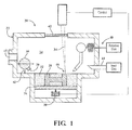
- FIG. 1 schematically illustrates a Direct Metal Laser Sintering (DMLS) system 20 that may have particular applicability to an additive manufacturing process.
- the system 20 generally incudes a process chamber 22 that forms a process space 24 in which a plate 26 for a component 28 (additively manufactured component 28) to be produced is located.
- This reception plate 26 can be lowered by an actuator 30, so that the component 28 can be produced in a stock of powder 32 of the material for the component, while, in each case after a ply of the component 28 has been produced by a laser beam 34, the reception plate 26 is lowered by the thickness of the ply.
- a movable stock container 36 with a dispenser 38 and a recoater blade 40 can be moved over and above the stock or powder 32, with the result that, after the lowering of the reception plate 26, a further ply of powder can be applied and leveled the recoater blade 40.
- the process chamber 22 includes a window 42 through which the laser beam 34 is directed. Furthermore, the process chamber has an inlet 44 and an outlet 45 through which a process gas is conducted through the process chamber 22. This inert process gas sweeps over the surface of the component 28, to minimize unwanted reactions of the melting bath 46 of component material with gaseous constituents so as to discharge possible evaporation products of the component material through the outlet 45.
- a feed gas 48 may also be provided through which a reactive gas can be communicated to causes the formation of a layer region with a composition different from that of the component material.
- DMLS Direct Metal Laser Sintering
- SLM selective laser melting
- the additive manufacturing process sequentially builds-up layers of atomized alloy and/or ceramic powder material that include but are not limited to, 625 Alloy, 718 Alloy, 230 Alloy, stainless steel, tool steel, cobalt chrome, titanium, nickel, aluminum and others in atomized powder material form. Alloys such as 625, 718 and 230 may have specific benefit for parts that operate in high temperature environments, such as, for example, environments typically encountered by aerospace and gas turbine engine components.
- the additive manufacturing process facilitates manufacture of relatively complex geometry components to minimize assembly details and multi-component construction.
- the additive manufacturing process fabricates or "grows" components using three-dimensional information, for example a three-dimensional computer model.
- the three-dimensional information is converted into a plurality of slices, each slice defining a cross section of the component for a predetermined height of the slice.
- the additive manufactured component is then "grown" slice by slice, or ply by ply, until finished.
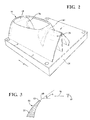
- the additively manufactured component 28 is grown on the reception plate 26 and the recoater blade 40 sweeps across the surface thereof in a linear recoat direction as indicated by arrow W.
- the manufactured component 28 includes an edge 60 that is arranged at an acute build angle A with respect to movement of the recoater blade 40 ( Figure 3 ).
- the edge 60 is formed by a lip 62 that that rolls inward such as is typical of an aerodynamic intake.
- one side 64 of the edge 60 is "friendly” to the linear recoat direction as it forms an obtuse angle
- the opposite side 66 of the edge 60 is “unfriendly” to the linear recoat direction as it forms an acute angle.
- an additively manufactured non-contact support 70 that does not form a part of the additively manufactured component 28 is simultaneously additively manufactured on the reception plate 26 to operate as a buffer between the acute build angles and the recoater blade 40.
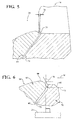
- the additively manufactured non-contact support 70 includes a non-contact support contoured surface 72 that is essentially the leeward side of the non-contact support contoured surface 72 with respect to the linear recoat direction W.
- the non-contact support contoured surface 72 is spaced from the additively manufactured component 28 by a space distance 74 about 0.003 - 0.015 inches (3-15 thou; 0.076 - 0.381 mm), and more particularly, by about 0.005 - 0.01 inches (0.127 - 0.254 mm) parallel to an X-Y plane defined by the reception plate 26 ( Figure 5 ).
- the space distance 74 is arranged to follow a contour 68 of the opposite side 66 of the edge 60 until the contour 68 become vertical, i.e., perpendicular to the X-Y plane ( Figure 6 ).
- the contoured surface 72 of the non-contoured support 70 may extend to a vertical 76 or even form an obtuse angle 78 ( Figure 6 ) to the linear recoat direction "W" of the recoater blade 40 to form a surface more amenable to the DMLS process that readily allows the recoater blade 40 to pass gently to the angled surface on the additively manufactured component 28.
- a windward side 80 of the non-contact support 70 is opposite the non-contact support contoured surface 72 with respect to the linear recoat direction W.
- the windward side 80 may be formed at various angles and directions, to provide a surface amenable to the DMLS process that readily allows the recoater blade 40 to pass as the additively manufactured non-contact support 70 does not form a part of the additively manufactured component 28.
- the additively manufactured non-contact support 70 and the additively manufactured component 28 are removed from the reception plate 26 such as via electron discharge machining or other conventional process such that the additively manufactured non-contact support 70 simply falls away or separates from the additively manufactured component 28.
- Utilization of the additively manufactured non-contact support 70 further opens the window as to what components can be constructed via additive manufacturing.
Landscapes
- Chemical & Material Sciences (AREA)
- Engineering & Computer Science (AREA)
- Materials Engineering (AREA)
- Manufacturing & Machinery (AREA)
- Physics & Mathematics (AREA)
- Optics & Photonics (AREA)
- Mechanical Engineering (AREA)
- Powder Metallurgy (AREA)
Applications Claiming Priority (1)
| Application Number | Priority Date | Filing Date | Title |
|---|---|---|---|
| US14/620,566 US10668532B2 (en) | 2015-02-12 | 2015-02-12 | Additively manufactured non-contact support |
Publications (2)
| Publication Number | Publication Date |
|---|---|
| EP3056301A1 true EP3056301A1 (de) | 2016-08-17 |
| EP3056301B1 EP3056301B1 (de) | 2019-12-18 |
Family
ID=55353063
Family Applications (1)
| Application Number | Title | Priority Date | Filing Date |
|---|---|---|---|
| EP16155047.0A Active EP3056301B1 (de) | 2015-02-12 | 2016-02-10 | Generativer herstellungsprozess eines objekts und angepasster kontaktloser stütze |
Country Status (2)
| Country | Link |
|---|---|
| US (2) | US10668532B2 (de) |
| EP (1) | EP3056301B1 (de) |
Cited By (5)
| Publication number | Priority date | Publication date | Assignee | Title |
|---|---|---|---|---|
| EP3205425A1 (de) * | 2016-02-11 | 2017-08-16 | General Electric Company | Verfahren und vorderkantenträger zur generativen fertigung |
| GB2560155A (en) * | 2017-02-16 | 2018-09-05 | Rolls Royce Plc | Additive layer support structure |
| EP3378584A1 (de) * | 2017-03-24 | 2018-09-26 | SLM Solutions Group AG | Vorrichtung und verfahren zur herstellung eines dreidimensionalen werkstücks |
| EP3760345A1 (de) * | 2019-07-04 | 2021-01-06 | Siemens Aktiengesellschaft | Computerimplementiertes verfahren zur berechnung und verfahren zur unterstützung der generativen fertigung |
| CN113199750A (zh) * | 2021-06-21 | 2021-08-03 | 安庆瑞迈特科技有限公司 | 一种准直器的高效3d打印方法 |
Families Citing this family (14)
| Publication number | Priority date | Publication date | Assignee | Title |
|---|---|---|---|---|
| US9643281B1 (en) * | 2016-01-08 | 2017-05-09 | Florida Turbine Technologies, Inc. | Process of forming a metal part from a metal powder using a laser to melt the metal powder over a support surface that can be easily removed after the metal part has been formed |
| US20230141106A1 (en) * | 2016-07-22 | 2023-05-11 | Postprocess Technologies, Inc. | Surface Equalization Apparatus |
| US9956612B1 (en) * | 2017-01-13 | 2018-05-01 | General Electric Company | Additive manufacturing using a mobile scan area |
| US10022794B1 (en) | 2017-01-13 | 2018-07-17 | General Electric Company | Additive manufacturing using a mobile build volume |
| US10022795B1 (en) | 2017-01-13 | 2018-07-17 | General Electric Company | Large scale additive machine |
| US20180200962A1 (en) | 2017-01-13 | 2018-07-19 | General Electric Company | Additive manufacturing using a dynamically grown build envelope |
| US11167454B2 (en) | 2017-01-13 | 2021-11-09 | General Electric Company | Method and apparatus for continuously refreshing a recoater blade for additive manufacturing |
| US10478893B1 (en) * | 2017-01-13 | 2019-11-19 | General Electric Company | Additive manufacturing using a selective recoater |
| US10359764B1 (en) * | 2017-12-29 | 2019-07-23 | Palo Alto Research Center Incorporated | System and method for planning support removal in hybrid manufacturing with the aid of a digital computer |
| US10493527B1 (en) | 2018-05-08 | 2019-12-03 | General Electric Company | System for additive manufacturing |
| US11117329B2 (en) | 2018-06-26 | 2021-09-14 | General Electric Company | Additively manufactured build assemblies having reduced distortion and residual stress |
| US11440097B2 (en) | 2019-02-12 | 2022-09-13 | General Electric Company | Methods for additively manufacturing components using lattice support structures |
| EP4223437B1 (de) * | 2022-02-07 | 2024-05-22 | Incus GmbH | Verfahren und vorrichtung zur additiven fertigung eines bauteils |
| GB202211722D0 (en) * | 2022-08-11 | 2022-09-28 | Rolls Royce Plc | A method of manufacturing a component |
Citations (4)
| Publication number | Priority date | Publication date | Assignee | Title |
|---|---|---|---|---|
| EP1486318A2 (de) * | 2003-06-02 | 2004-12-15 | Hewlett-Packard Development Company, L.P. | Verfahren und System zur Herstellung eines Formteils durch 'Solid Freeform Fabrication' |
| US20130112366A1 (en) * | 2010-07-01 | 2013-05-09 | Snecma | Process for manufacturing a metal part by selectively melting a powder |
| GB2515287A (en) * | 2013-06-17 | 2014-12-24 | Rolls Royce Plc | An Additive Layer Manufacturing Method |
| WO2014208743A1 (ja) * | 2013-06-28 | 2014-12-31 | シーメット株式会社 | 三次元造形体およびサポート形成方法 |
Family Cites Families (12)
| Publication number | Priority date | Publication date | Assignee | Title |
|---|---|---|---|---|
| US5352405A (en) * | 1992-12-18 | 1994-10-04 | Dtm Corporation | Thermal control of selective laser sintering via control of the laser scan |
| DE19853979A1 (de) | 1998-11-23 | 2000-05-31 | Fraunhofer Ges Forschung | Vorrichtung und Verfahren zum Abtasten einer Objektfläche mit einem Laserstrahl, insbesondere zum selektiven Laser-Schmelzen |
| EP1234625A1 (de) | 2001-02-21 | 2002-08-28 | Trumpf Werkzeugmaschinen GmbH + Co. KG | Verfahren und Vorrichtung zur Herstellung eines Formkörpers durch selektives Laserschmelzen |
| DE10219983B4 (de) * | 2002-05-03 | 2004-03-18 | Bego Medical Ag | Verfahren zum Herstellen von Produkten durch Freiform-Lasersintern |
| US6815636B2 (en) * | 2003-04-09 | 2004-11-09 | 3D Systems, Inc. | Sintering using thermal image feedback |
| US7521652B2 (en) * | 2004-12-07 | 2009-04-21 | 3D Systems, Inc. | Controlled cooling methods and apparatus for laser sintering part-cake |
| CN100586611C (zh) | 2008-02-27 | 2010-02-03 | 华南理工大学 | 定制化舌侧正畸托槽的选区激光熔化直接制造方法 |
| DE102008030186A1 (de) | 2008-06-26 | 2009-12-31 | Siemens Aktiengesellschaft | Verfahren zum Erzeugen eines Bauteils durch selektives Laserschmelzen sowie hierfür geeignete Prozesskammer |
| DE102008044759B4 (de) | 2008-08-28 | 2013-09-19 | Airbus Operations Gmbh | Stütze für ein im Selective Laser Melting-Verfahren herstellbares Flugzeugstrukturbauteil |
| DE102008060860A1 (de) | 2008-12-09 | 2010-06-10 | Josef Hintersehr | Verfahren zur genauen Fertigung von Dentalkomponenten mit einem Sinter oder SLM Verfahren |
| EP2319641B1 (de) | 2009-10-30 | 2017-07-19 | Ansaldo Energia IP UK Limited | Verfahren zur Anwendung mehrerer Materialien mit selektivem Laserschmelzen auf einem dreidimensionalen Artikel |
| EP2359964B1 (de) | 2010-01-26 | 2013-11-20 | Alstom Technology Ltd | Verfahren zum Herstellen eines 3-dimensionalen Bauteils mittels selektiven Laserschmelzens (SLM) |
-
2015
- 2015-02-12 US US14/620,566 patent/US10668532B2/en active Active
-
2016
- 2016-02-10 EP EP16155047.0A patent/EP3056301B1/de active Active
-
2020
- 2020-04-28 US US16/860,534 patent/US11565326B2/en active Active
Patent Citations (5)
| Publication number | Priority date | Publication date | Assignee | Title |
|---|---|---|---|---|
| EP1486318A2 (de) * | 2003-06-02 | 2004-12-15 | Hewlett-Packard Development Company, L.P. | Verfahren und System zur Herstellung eines Formteils durch 'Solid Freeform Fabrication' |
| US20130112366A1 (en) * | 2010-07-01 | 2013-05-09 | Snecma | Process for manufacturing a metal part by selectively melting a powder |
| GB2515287A (en) * | 2013-06-17 | 2014-12-24 | Rolls Royce Plc | An Additive Layer Manufacturing Method |
| WO2014208743A1 (ja) * | 2013-06-28 | 2014-12-31 | シーメット株式会社 | 三次元造形体およびサポート形成方法 |
| EP3015251A1 (de) * | 2013-06-28 | 2016-05-04 | Cmet Inc. | Dreidimensionaler formkörper und stützenherstellungsverfahren |
Cited By (10)
| Publication number | Priority date | Publication date | Assignee | Title |
|---|---|---|---|---|
| EP3205425A1 (de) * | 2016-02-11 | 2017-08-16 | General Electric Company | Verfahren und vorderkantenträger zur generativen fertigung |
| US10357828B2 (en) | 2016-02-11 | 2019-07-23 | General Electric Company | Methods and leading edge supports for additive manufacturing |
| GB2560155A (en) * | 2017-02-16 | 2018-09-05 | Rolls Royce Plc | Additive layer support structure |
| EP3378584A1 (de) * | 2017-03-24 | 2018-09-26 | SLM Solutions Group AG | Vorrichtung und verfahren zur herstellung eines dreidimensionalen werkstücks |
| WO2018172089A1 (en) * | 2017-03-24 | 2018-09-27 | SLM Solutions Group AG | Device and method for producing a three-dimensional workpiece |
| CN110573277A (zh) * | 2017-03-24 | 2019-12-13 | Slm方案集团股份公司 | 用于生产三维工件的装置和方法 |
| EP3760345A1 (de) * | 2019-07-04 | 2021-01-06 | Siemens Aktiengesellschaft | Computerimplementiertes verfahren zur berechnung und verfahren zur unterstützung der generativen fertigung |
| WO2021001076A1 (en) * | 2019-07-04 | 2021-01-07 | Siemens Energy Global GmbH & Co. KG | Computer-implemented method of calculation and method of supporting for additive manufacturing |
| CN113199750A (zh) * | 2021-06-21 | 2021-08-03 | 安庆瑞迈特科技有限公司 | 一种准直器的高效3d打印方法 |
| CN113199750B (zh) * | 2021-06-21 | 2022-01-07 | 安庆瑞迈特科技有限公司 | 一种准直器的高效3d打印方法 |
Also Published As
| Publication number | Publication date |
|---|---|
| US20200254525A1 (en) | 2020-08-13 |
| US10668532B2 (en) | 2020-06-02 |
| US20160236277A1 (en) | 2016-08-18 |
| US11565326B2 (en) | 2023-01-31 |
| EP3056301B1 (de) | 2019-12-18 |
Similar Documents
| Publication | Publication Date | Title |
|---|---|---|
| US11565326B2 (en) | Additively manufactured non-contact support | |
| EP2754515B1 (de) | Verfahren zur herstellung von gasturbinenmotorkomponenten mittels additiver herstellungsverfahren. | |
| Yakout et al. | On the characterization of stainless steel 316L parts produced by selective laser melting | |
| US9796048B2 (en) | Article and process for producing an article | |
| US8691329B2 (en) | Laser net shape manufacturing using an adaptive toolpath deposition method | |
| EP2692464B1 (de) | Verfahren zur Herstellung von Titanaluminidkomponenten aus durch Konsolidierungsverfahren geformten Artikeln | |
| US20100028158A1 (en) | High-pressure turbine blade and procedure for repair of high-pressure turbine blades | |
| Gebisa et al. | Additive manufacturing for the manufacture of gas turbine engine components: Literature review and future perspectives | |
| US8506836B2 (en) | Methods for manufacturing components from articles formed by additive-manufacturing processes | |
| US20160258298A1 (en) | Process for producing an article | |
| US11484943B2 (en) | Additive manufacturing of metal matrix composite feedstock | |
| EP2905097A2 (de) | Schichtweise hergestellter artikel | |
| US20210046713A1 (en) | Additive manufactured multi-portion article | |
| WO2019014445A1 (en) | METHOD FOR REPAIRING AN ARTICLE AND RELATED ARTICLE | |
| US20200246871A1 (en) | Additive manufacturing cover gas shield | |
| US20190143396A1 (en) | Core for high-temperature shaping of a metal part and manufacturing process | |
| AU2019382600B2 (en) | A method for the additive production of an article | |
| EP3492623B1 (de) | Verfahren zur reduzierung der oberflächenrauheit | |
| US11415001B1 (en) | Cooling hole filter configuration |
Legal Events
| Date | Code | Title | Description |
|---|---|---|---|
| PUAI | Public reference made under article 153(3) epc to a published international application that has entered the european phase |
Free format text: ORIGINAL CODE: 0009012 |
|
| AK | Designated contracting states |
Kind code of ref document: A1 Designated state(s): AL AT BE BG CH CY CZ DE DK EE ES FI FR GB GR HR HU IE IS IT LI LT LU LV MC MK MT NL NO PL PT RO RS SE SI SK SM TR |
|
| AX | Request for extension of the european patent |
Extension state: BA ME |
|
| RAP1 | Party data changed (applicant data changed or rights of an application transferred) |
Owner name: UNITED TECHNOLOGIES CORPORATION |
|
| STAA | Information on the status of an ep patent application or granted ep patent |
Free format text: STATUS: REQUEST FOR EXAMINATION WAS MADE |
|
| 17P | Request for examination filed |
Effective date: 20170217 |
|
| RBV | Designated contracting states (corrected) |
Designated state(s): AL AT BE BG CH CY CZ DE DK EE ES FI FR GB GR HR HU IE IS IT LI LT LU LV MC MK MT NL NO PL PT RO RS SE SI SK SM TR |
|
| REG | Reference to a national code |
Ref country code: DE Ref legal event code: R079 Ref document number: 602016026218 Country of ref document: DE Free format text: PREVIOUS MAIN CLASS: B22F0003105000 Ipc: B33Y0010000000 |
|
| GRAP | Despatch of communication of intention to grant a patent |
Free format text: ORIGINAL CODE: EPIDOSNIGR1 |
|
| STAA | Information on the status of an ep patent application or granted ep patent |
Free format text: STATUS: GRANT OF PATENT IS INTENDED |
|
| RIC1 | Information provided on ipc code assigned before grant |
Ipc: B22F 3/105 20060101ALI20190531BHEP Ipc: B29C 64/153 20170101ALI20190531BHEP Ipc: B33Y 10/00 20150101AFI20190531BHEP Ipc: B29C 64/40 20170101ALI20190531BHEP |
|
| INTG | Intention to grant announced |
Effective date: 20190705 |
|
| GRAS | Grant fee paid |
Free format text: ORIGINAL CODE: EPIDOSNIGR3 |
|
| GRAA | (expected) grant |
Free format text: ORIGINAL CODE: 0009210 |
|
| STAA | Information on the status of an ep patent application or granted ep patent |
Free format text: STATUS: THE PATENT HAS BEEN GRANTED |
|
| AK | Designated contracting states |
Kind code of ref document: B1 Designated state(s): AL AT BE BG CH CY CZ DE DK EE ES FI FR GB GR HR HU IE IS IT LI LT LU LV MC MK MT NL NO PL PT RO RS SE SI SK SM TR |
|
| REG | Reference to a national code |
Ref country code: CH Ref legal event code: EP |
|
| REG | Reference to a national code |
Ref country code: DE Ref legal event code: R096 Ref document number: 602016026218 Country of ref document: DE |
|
| REG | Reference to a national code |
Ref country code: IE Ref legal event code: FG4D |
|
| REG | Reference to a national code |
Ref country code: AT Ref legal event code: REF Ref document number: 1214138 Country of ref document: AT Kind code of ref document: T Effective date: 20200115 |
|
| REG | Reference to a national code |
Ref country code: NL Ref legal event code: MP Effective date: 20191218 |
|
| PG25 | Lapsed in a contracting state [announced via postgrant information from national office to epo] |
Ref country code: NO Free format text: LAPSE BECAUSE OF FAILURE TO SUBMIT A TRANSLATION OF THE DESCRIPTION OR TO PAY THE FEE WITHIN THE PRESCRIBED TIME-LIMIT Effective date: 20200318 Ref country code: GR Free format text: LAPSE BECAUSE OF FAILURE TO SUBMIT A TRANSLATION OF THE DESCRIPTION OR TO PAY THE FEE WITHIN THE PRESCRIBED TIME-LIMIT Effective date: 20200319 Ref country code: BG Free format text: LAPSE BECAUSE OF FAILURE TO SUBMIT A TRANSLATION OF THE DESCRIPTION OR TO PAY THE FEE WITHIN THE PRESCRIBED TIME-LIMIT Effective date: 20200318 Ref country code: LT Free format text: LAPSE BECAUSE OF FAILURE TO SUBMIT A TRANSLATION OF THE DESCRIPTION OR TO PAY THE FEE WITHIN THE PRESCRIBED TIME-LIMIT Effective date: 20191218 Ref country code: SE Free format text: LAPSE BECAUSE OF FAILURE TO SUBMIT A TRANSLATION OF THE DESCRIPTION OR TO PAY THE FEE WITHIN THE PRESCRIBED TIME-LIMIT Effective date: 20191218 Ref country code: LV Free format text: LAPSE BECAUSE OF FAILURE TO SUBMIT A TRANSLATION OF THE DESCRIPTION OR TO PAY THE FEE WITHIN THE PRESCRIBED TIME-LIMIT Effective date: 20191218 Ref country code: FI Free format text: LAPSE BECAUSE OF FAILURE TO SUBMIT A TRANSLATION OF THE DESCRIPTION OR TO PAY THE FEE WITHIN THE PRESCRIBED TIME-LIMIT Effective date: 20191218 |
|
| REG | Reference to a national code |
Ref country code: LT Ref legal event code: MG4D |
|
| PG25 | Lapsed in a contracting state [announced via postgrant information from national office to epo] |
Ref country code: RS Free format text: LAPSE BECAUSE OF FAILURE TO SUBMIT A TRANSLATION OF THE DESCRIPTION OR TO PAY THE FEE WITHIN THE PRESCRIBED TIME-LIMIT Effective date: 20191218 Ref country code: HR Free format text: LAPSE BECAUSE OF FAILURE TO SUBMIT A TRANSLATION OF THE DESCRIPTION OR TO PAY THE FEE WITHIN THE PRESCRIBED TIME-LIMIT Effective date: 20191218 |
|
| PG25 | Lapsed in a contracting state [announced via postgrant information from national office to epo] |
Ref country code: AL Free format text: LAPSE BECAUSE OF FAILURE TO SUBMIT A TRANSLATION OF THE DESCRIPTION OR TO PAY THE FEE WITHIN THE PRESCRIBED TIME-LIMIT Effective date: 20191218 |
|
| PG25 | Lapsed in a contracting state [announced via postgrant information from national office to epo] |
Ref country code: EE Free format text: LAPSE BECAUSE OF FAILURE TO SUBMIT A TRANSLATION OF THE DESCRIPTION OR TO PAY THE FEE WITHIN THE PRESCRIBED TIME-LIMIT Effective date: 20191218 Ref country code: CZ Free format text: LAPSE BECAUSE OF FAILURE TO SUBMIT A TRANSLATION OF THE DESCRIPTION OR TO PAY THE FEE WITHIN THE PRESCRIBED TIME-LIMIT Effective date: 20191218 Ref country code: PT Free format text: LAPSE BECAUSE OF FAILURE TO SUBMIT A TRANSLATION OF THE DESCRIPTION OR TO PAY THE FEE WITHIN THE PRESCRIBED TIME-LIMIT Effective date: 20200513 Ref country code: RO Free format text: LAPSE BECAUSE OF FAILURE TO SUBMIT A TRANSLATION OF THE DESCRIPTION OR TO PAY THE FEE WITHIN THE PRESCRIBED TIME-LIMIT Effective date: 20191218 Ref country code: NL Free format text: LAPSE BECAUSE OF FAILURE TO SUBMIT A TRANSLATION OF THE DESCRIPTION OR TO PAY THE FEE WITHIN THE PRESCRIBED TIME-LIMIT Effective date: 20191218 |
|
| PG25 | Lapsed in a contracting state [announced via postgrant information from national office to epo] |
Ref country code: IS Free format text: LAPSE BECAUSE OF FAILURE TO SUBMIT A TRANSLATION OF THE DESCRIPTION OR TO PAY THE FEE WITHIN THE PRESCRIBED TIME-LIMIT Effective date: 20200418 Ref country code: SK Free format text: LAPSE BECAUSE OF FAILURE TO SUBMIT A TRANSLATION OF THE DESCRIPTION OR TO PAY THE FEE WITHIN THE PRESCRIBED TIME-LIMIT Effective date: 20191218 Ref country code: SM Free format text: LAPSE BECAUSE OF FAILURE TO SUBMIT A TRANSLATION OF THE DESCRIPTION OR TO PAY THE FEE WITHIN THE PRESCRIBED TIME-LIMIT Effective date: 20191218 |
|
| REG | Reference to a national code |
Ref country code: DE Ref legal event code: R097 Ref document number: 602016026218 Country of ref document: DE |
|
| REG | Reference to a national code |
Ref country code: CH Ref legal event code: PL |
|
| REG | Reference to a national code |
Ref country code: AT Ref legal event code: MK05 Ref document number: 1214138 Country of ref document: AT Kind code of ref document: T Effective date: 20191218 |
|
| PLBE | No opposition filed within time limit |
Free format text: ORIGINAL CODE: 0009261 |
|
| STAA | Information on the status of an ep patent application or granted ep patent |
Free format text: STATUS: NO OPPOSITION FILED WITHIN TIME LIMIT |
|
| REG | Reference to a national code |
Ref country code: BE Ref legal event code: MM Effective date: 20200229 |
|
| PG25 | Lapsed in a contracting state [announced via postgrant information from national office to epo] |
Ref country code: DK Free format text: LAPSE BECAUSE OF FAILURE TO SUBMIT A TRANSLATION OF THE DESCRIPTION OR TO PAY THE FEE WITHIN THE PRESCRIBED TIME-LIMIT Effective date: 20191218 Ref country code: MC Free format text: LAPSE BECAUSE OF FAILURE TO SUBMIT A TRANSLATION OF THE DESCRIPTION OR TO PAY THE FEE WITHIN THE PRESCRIBED TIME-LIMIT Effective date: 20191218 Ref country code: LU Free format text: LAPSE BECAUSE OF NON-PAYMENT OF DUE FEES Effective date: 20200210 Ref country code: ES Free format text: LAPSE BECAUSE OF FAILURE TO SUBMIT A TRANSLATION OF THE DESCRIPTION OR TO PAY THE FEE WITHIN THE PRESCRIBED TIME-LIMIT Effective date: 20191218 |
|
| 26N | No opposition filed |
Effective date: 20200921 |
|
| PG25 | Lapsed in a contracting state [announced via postgrant information from national office to epo] |
Ref country code: LI Free format text: LAPSE BECAUSE OF NON-PAYMENT OF DUE FEES Effective date: 20200229 Ref country code: SI Free format text: LAPSE BECAUSE OF FAILURE TO SUBMIT A TRANSLATION OF THE DESCRIPTION OR TO PAY THE FEE WITHIN THE PRESCRIBED TIME-LIMIT Effective date: 20191218 Ref country code: CH Free format text: LAPSE BECAUSE OF NON-PAYMENT OF DUE FEES Effective date: 20200229 Ref country code: AT Free format text: LAPSE BECAUSE OF FAILURE TO SUBMIT A TRANSLATION OF THE DESCRIPTION OR TO PAY THE FEE WITHIN THE PRESCRIBED TIME-LIMIT Effective date: 20191218 |
|
| PG25 | Lapsed in a contracting state [announced via postgrant information from national office to epo] |
Ref country code: IT Free format text: LAPSE BECAUSE OF FAILURE TO SUBMIT A TRANSLATION OF THE DESCRIPTION OR TO PAY THE FEE WITHIN THE PRESCRIBED TIME-LIMIT Effective date: 20191218 Ref country code: IE Free format text: LAPSE BECAUSE OF NON-PAYMENT OF DUE FEES Effective date: 20200210 |
|
| PG25 | Lapsed in a contracting state [announced via postgrant information from national office to epo] |
Ref country code: BE Free format text: LAPSE BECAUSE OF NON-PAYMENT OF DUE FEES Effective date: 20200229 Ref country code: PL Free format text: LAPSE BECAUSE OF FAILURE TO SUBMIT A TRANSLATION OF THE DESCRIPTION OR TO PAY THE FEE WITHIN THE PRESCRIBED TIME-LIMIT Effective date: 20191218 |
|
| PG25 | Lapsed in a contracting state [announced via postgrant information from national office to epo] |
Ref country code: TR Free format text: LAPSE BECAUSE OF FAILURE TO SUBMIT A TRANSLATION OF THE DESCRIPTION OR TO PAY THE FEE WITHIN THE PRESCRIBED TIME-LIMIT Effective date: 20191218 Ref country code: MT Free format text: LAPSE BECAUSE OF FAILURE TO SUBMIT A TRANSLATION OF THE DESCRIPTION OR TO PAY THE FEE WITHIN THE PRESCRIBED TIME-LIMIT Effective date: 20191218 Ref country code: CY Free format text: LAPSE BECAUSE OF FAILURE TO SUBMIT A TRANSLATION OF THE DESCRIPTION OR TO PAY THE FEE WITHIN THE PRESCRIBED TIME-LIMIT Effective date: 20191218 |
|
| PG25 | Lapsed in a contracting state [announced via postgrant information from national office to epo] |
Ref country code: MK Free format text: LAPSE BECAUSE OF FAILURE TO SUBMIT A TRANSLATION OF THE DESCRIPTION OR TO PAY THE FEE WITHIN THE PRESCRIBED TIME-LIMIT Effective date: 20191218 |
|
| REG | Reference to a national code |
Ref country code: DE Ref legal event code: R081 Ref document number: 602016026218 Country of ref document: DE Owner name: RAYTHEON TECHNOLOGIES CORPORATION (N.D.GES.D.S, US Free format text: FORMER OWNER: UNITED TECHNOLOGIES CORPORATION, FARMINGTON, CONN., US Ref country code: DE Ref legal event code: R081 Ref document number: 602016026218 Country of ref document: DE Owner name: RTX CORPORATION (N.D.GES.D. STAATES DELAWARE),, US Free format text: FORMER OWNER: UNITED TECHNOLOGIES CORPORATION, FARMINGTON, CONN., US |
|
| P01 | Opt-out of the competence of the unified patent court (upc) registered |
Effective date: 20230520 |
|
| REG | Reference to a national code |
Ref country code: DE Ref legal event code: R081 Ref document number: 602016026218 Country of ref document: DE Owner name: RTX CORPORATION (N.D.GES.D. STAATES DELAWARE),, US Free format text: FORMER OWNER: RAYTHEON TECHNOLOGIES CORPORATION (N.D.GES.D.STAATES DELAWARE), ARLINGTON, VA, US |
|
| PGFP | Annual fee paid to national office [announced via postgrant information from national office to epo] |
Ref country code: GB Payment date: 20260121 Year of fee payment: 11 |
|
| PGFP | Annual fee paid to national office [announced via postgrant information from national office to epo] |
Ref country code: DE Payment date: 20260121 Year of fee payment: 11 |
|
| PGFP | Annual fee paid to national office [announced via postgrant information from national office to epo] |
Ref country code: FR Payment date: 20260121 Year of fee payment: 11 |