EP3056667A2 - Turbinenschaufel zur steuerung von radraumspülluft - Google Patents
Turbinenschaufel zur steuerung von radraumspülluft Download PDFInfo
- Publication number
- EP3056667A2 EP3056667A2 EP16152213.1A EP16152213A EP3056667A2 EP 3056667 A2 EP3056667 A2 EP 3056667A2 EP 16152213 A EP16152213 A EP 16152213A EP 3056667 A2 EP3056667 A2 EP 3056667A2
- Authority
- EP
- European Patent Office
- Prior art keywords
- angel wing
- turbine bucket
- voids
- extending radially
- rim
- Prior art date
- Legal status (The legal status is an assumption and is not a legal conclusion. Google has not performed a legal analysis and makes no representation as to the accuracy of the status listed.)
- Withdrawn
Links
- 238000010926 purge Methods 0.000 title claims abstract description 42
- 241000879887 Cyrtopleura costata Species 0.000 claims abstract description 88
- 241000725175 Caladium bicolor Species 0.000 description 4
- 235000015966 Pleurocybella porrigens Nutrition 0.000 description 4
- 230000000694 effects Effects 0.000 description 4
- 238000002485 combustion reaction Methods 0.000 description 3
- 230000006870 function Effects 0.000 description 3
- 239000000463 material Substances 0.000 description 3
- 230000009467 reduction Effects 0.000 description 3
- 239000011800 void material Substances 0.000 description 3
- 238000001816 cooling Methods 0.000 description 2
- 230000003628 erosive effect Effects 0.000 description 2
- 230000002349 favourable effect Effects 0.000 description 2
- 241000264877 Hippospongia communis Species 0.000 description 1
- 230000003247 decreasing effect Effects 0.000 description 1
- 238000000034 method Methods 0.000 description 1
- 238000000926 separation method Methods 0.000 description 1
Images


Classifications
-
- F—MECHANICAL ENGINEERING; LIGHTING; HEATING; WEAPONS; BLASTING
- F01—MACHINES OR ENGINES IN GENERAL; ENGINE PLANTS IN GENERAL; STEAM ENGINES
- F01D—NON-POSITIVE DISPLACEMENT MACHINES OR ENGINES, e.g. STEAM TURBINES
- F01D5/00—Blades; Blade-carrying members; Heating, heat-insulating, cooling or antivibration means on the blades or the members
- F01D5/12—Blades
- F01D5/14—Form or construction
- F01D5/147—Construction, i.e. structural features, e.g. of weight-saving hollow blades
-
- F—MECHANICAL ENGINEERING; LIGHTING; HEATING; WEAPONS; BLASTING
- F01—MACHINES OR ENGINES IN GENERAL; ENGINE PLANTS IN GENERAL; STEAM ENGINES
- F01D—NON-POSITIVE DISPLACEMENT MACHINES OR ENGINES, e.g. STEAM TURBINES
- F01D11/00—Preventing or minimising internal leakage of working-fluid, e.g. between stages
- F01D11/001—Preventing or minimising internal leakage of working-fluid, e.g. between stages for sealing space between stator blade and rotor
-
- F—MECHANICAL ENGINEERING; LIGHTING; HEATING; WEAPONS; BLASTING
- F01—MACHINES OR ENGINES IN GENERAL; ENGINE PLANTS IN GENERAL; STEAM ENGINES
- F01D—NON-POSITIVE DISPLACEMENT MACHINES OR ENGINES, e.g. STEAM TURBINES
- F01D11/00—Preventing or minimising internal leakage of working-fluid, e.g. between stages
- F01D11/005—Sealing means between non relatively rotating elements
- F01D11/006—Sealing the gap between rotor blades or blades and rotor
-
- F—MECHANICAL ENGINEERING; LIGHTING; HEATING; WEAPONS; BLASTING
- F01—MACHINES OR ENGINES IN GENERAL; ENGINE PLANTS IN GENERAL; STEAM ENGINES
- F01D—NON-POSITIVE DISPLACEMENT MACHINES OR ENGINES, e.g. STEAM TURBINES
- F01D11/00—Preventing or minimising internal leakage of working-fluid, e.g. between stages
- F01D11/02—Preventing or minimising internal leakage of working-fluid, e.g. between stages by non-contact sealings, e.g. of labyrinth type
-
- F—MECHANICAL ENGINEERING; LIGHTING; HEATING; WEAPONS; BLASTING
- F01—MACHINES OR ENGINES IN GENERAL; ENGINE PLANTS IN GENERAL; STEAM ENGINES
- F01D—NON-POSITIVE DISPLACEMENT MACHINES OR ENGINES, e.g. STEAM TURBINES
- F01D5/00—Blades; Blade-carrying members; Heating, heat-insulating, cooling or antivibration means on the blades or the members
- F01D5/02—Blade-carrying members, e.g. rotors
- F01D5/08—Heating, heat-insulating or cooling means
- F01D5/081—Cooling fluid being directed on the side of the rotor disc or at the roots of the blades
- F01D5/082—Cooling fluid being directed on the side of the rotor disc or at the roots of the blades on the side of the rotor disc
-
- F—MECHANICAL ENGINEERING; LIGHTING; HEATING; WEAPONS; BLASTING
- F01—MACHINES OR ENGINES IN GENERAL; ENGINE PLANTS IN GENERAL; STEAM ENGINES
- F01D—NON-POSITIVE DISPLACEMENT MACHINES OR ENGINES, e.g. STEAM TURBINES
- F01D5/00—Blades; Blade-carrying members; Heating, heat-insulating, cooling or antivibration means on the blades or the members
- F01D5/02—Blade-carrying members, e.g. rotors
- F01D5/08—Heating, heat-insulating or cooling means
- F01D5/085—Heating, heat-insulating or cooling means cooling fluid circulating inside the rotor
- F01D5/087—Heating, heat-insulating or cooling means cooling fluid circulating inside the rotor in the radial passages of the rotor disc
-
- F—MECHANICAL ENGINEERING; LIGHTING; HEATING; WEAPONS; BLASTING
- F01—MACHINES OR ENGINES IN GENERAL; ENGINE PLANTS IN GENERAL; STEAM ENGINES
- F01D—NON-POSITIVE DISPLACEMENT MACHINES OR ENGINES, e.g. STEAM TURBINES
- F01D5/00—Blades; Blade-carrying members; Heating, heat-insulating, cooling or antivibration means on the blades or the members
- F01D5/12—Blades
- F01D5/14—Form or construction
-
- F—MECHANICAL ENGINEERING; LIGHTING; HEATING; WEAPONS; BLASTING
- F01—MACHINES OR ENGINES IN GENERAL; ENGINE PLANTS IN GENERAL; STEAM ENGINES
- F01D—NON-POSITIVE DISPLACEMENT MACHINES OR ENGINES, e.g. STEAM TURBINES
- F01D9/00—Stators
- F01D9/02—Nozzles; Nozzle boxes; Stator blades; Guide conduits, e.g. individual nozzles
-
- F—MECHANICAL ENGINEERING; LIGHTING; HEATING; WEAPONS; BLASTING
- F05—INDEXING SCHEMES RELATING TO ENGINES OR PUMPS IN VARIOUS SUBCLASSES OF CLASSES F01-F04
- F05D—INDEXING SCHEME FOR ASPECTS RELATING TO NON-POSITIVE-DISPLACEMENT MACHINES OR ENGINES, GAS-TURBINES OR JET-PROPULSION PLANTS
- F05D2220/00—Application
- F05D2220/30—Application in turbines
- F05D2220/32—Application in turbines in gas turbines
-
- F—MECHANICAL ENGINEERING; LIGHTING; HEATING; WEAPONS; BLASTING
- F05—INDEXING SCHEMES RELATING TO ENGINES OR PUMPS IN VARIOUS SUBCLASSES OF CLASSES F01-F04
- F05D—INDEXING SCHEME FOR ASPECTS RELATING TO NON-POSITIVE-DISPLACEMENT MACHINES OR ENGINES, GAS-TURBINES OR JET-PROPULSION PLANTS
- F05D2240/00—Components
- F05D2240/10—Stators
- F05D2240/12—Fluid guiding means, e.g. vanes
-
- F—MECHANICAL ENGINEERING; LIGHTING; HEATING; WEAPONS; BLASTING
- F05—INDEXING SCHEMES RELATING TO ENGINES OR PUMPS IN VARIOUS SUBCLASSES OF CLASSES F01-F04
- F05D—INDEXING SCHEME FOR ASPECTS RELATING TO NON-POSITIVE-DISPLACEMENT MACHINES OR ENGINES, GAS-TURBINES OR JET-PROPULSION PLANTS
- F05D2240/00—Components
- F05D2240/20—Rotors
- F05D2240/30—Characteristics of rotor blades, i.e. of any element transforming dynamic fluid energy to or from rotational energy and being attached to a rotor
-
- F—MECHANICAL ENGINEERING; LIGHTING; HEATING; WEAPONS; BLASTING
- F05—INDEXING SCHEMES RELATING TO ENGINES OR PUMPS IN VARIOUS SUBCLASSES OF CLASSES F01-F04
- F05D—INDEXING SCHEME FOR ASPECTS RELATING TO NON-POSITIVE-DISPLACEMENT MACHINES OR ENGINES, GAS-TURBINES OR JET-PROPULSION PLANTS
- F05D2240/00—Components
- F05D2240/55—Seals
-
- F—MECHANICAL ENGINEERING; LIGHTING; HEATING; WEAPONS; BLASTING
- F05—INDEXING SCHEMES RELATING TO ENGINES OR PUMPS IN VARIOUS SUBCLASSES OF CLASSES F01-F04
- F05D—INDEXING SCHEME FOR ASPECTS RELATING TO NON-POSITIVE-DISPLACEMENT MACHINES OR ENGINES, GAS-TURBINES OR JET-PROPULSION PLANTS
- F05D2240/00—Components
- F05D2240/80—Platforms for stationary or moving blades
Definitions
- Embodiments of the invention relate generally to rotary machines and, more particularly, to the control of wheel space purge air in gas turbines.
- gas turbines employ rows of buckets on the wheels / disks of a rotor assembly, which alternate with rows of stationary vanes on a stator or nozzle assembly. These alternating rows extend axially along the rotor and stator and allow combustion gasses to turn the rotor as the combustion gasses flow therethrough.
- Axial / radial openings at the interface between rotating buckets and stationary nozzles can allow hot combustion gasses to exit the hot gas path and radially enter the intervening wheelspace between bucket rows.
- the bucket structures typically employ axially-projecting angel wings, which cooperate with discourager members extending axially from an adjacent stator or nozzle. These angel wings and discourager members overlap but do not touch, and serve to restrict incursion of hot gasses into the wheelspace.
- cooling air or "purge air” is often introduced into the wheelspace between bucket rows.
- This purge air serves to cool components and spaces within the wheelspaces and other regions radially inward from the buckets as well as providing a counter flow of cooling air to further restrict incursion of hot gasses into the wheelspace.
- Angel wing seals therefore are further designed to restrict escape of purge air into the hot gas flowpath.
- the invention provides a turbine bucket comprising: a platform portion; an airfoil extending radially outward from the platform portion; a shank portion extending radially inward from the platform portion; at least one angel wing extending axially from a face of the shank portion, the at least one angel wing including an angel wing rim extending radially upward toward the airfoil; and a plurality of voids disposed along the angel wing rim.
- the invention provides a turbine bucket comprising: a platform portion; an airfoil extending radially outward from the platform portion; a shank portion extending radially inward from the platform portion; at least one angel wing extending axially from a face of the shank portion, the at least one angel wing including an angel wing rim extending radially upward toward the airfoil; a plurality of voids disposed along the angel wing rim; and a plurality of dam members extending axially inward from the angel wing rim toward the face of the shank portion.
- the invention provides a gas turbine comprising: at least one turbine bucket extending radially outward from a rotating shaft, the at least one turbine bucket including: an airfoil extending radially outward from a platform; a shank portion extending radially inward from the platform portion; and at least one angel wing seal extending axially from a face of the shank portion, the at least one angel wing seal having an angel wing rim extending radially upward toward the airfoil; and a nozzle surface disposed radially outward from the at least one angel wing seal, the nozzle surface having a radially inwardly facing erodible portion adjacent the angel wing rim, wherein, in operation, the angel wing rim erodes a groove into the erodible portion of the nozzle surface.
- the invention provides a gas turbine comprising: a diffuser; and a last stage turbine bucket adjacent the diffuser, the last stage turbine bucket comprising: an airfoil extending radially outward from a platform portion; a shank portion extending radially inward from the platform portion; at least one angel wing extending axially from a face of the shank portion, the at least one angel wing including an angel wing rim extending radially upward toward the airfoil; and a plurality of voids disposed along the angel wing rim.
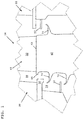
- FIG. 1 shows a schematic cross-sectional view of a portion of a gas turbine 10 including a bucket 40 disposed between a first stage nozzle 20 and a second stage nozzle 22.
- Bucket 40 extends radially outward from an axially extending rotor (not shown), as will be recognized by one skilled in the art.
- Bucket 40 comprises a substantially planar platform 42, an airfoil extending radially outward from platform 42, and a shank portion 60 extending radially inward from platform 42.
- Shank portion 60 includes a pair of angel wing seals 70, 72 extending axially outward toward first stage nozzle 20 and an angel wing seal 74 extending axially outward toward second stage nozzle 22. It should be understood that differing numbers and arrangements of angel wing seals are possible and within the scope of the invention. The number and arrangement of angel wing seals described herein are provided merely for purposes of illustration.
- nozzle surface 30 and discourager member 32 extend axially from first stage nozzle 20 and are disposed radially outward from angel wing seals 70 and 72, respectively. As such, nozzle surface 30 overlaps but does not contact angel wing seal 70 and discourager member 32 overlaps but does not contact angel wing seal 72.
- a similar arrangement is shown with respect to discourager member 32 of second stage nozzle 22 and angel wing seal 74.
- a quantity of purge air may be disposed between, for example, nozzle surface 30, angel wing seal 70, and platform lip 44, thereby restricting both escape of purge air into hot gas flowpath 28 and incursion of hot gasses from hot gas flowpath 28 into wheelspace 26.
- nozzle surface 30 and discourager member 32 each serves to restrict the escape of purge air and the incursion of hot gasses.
- a separate discourager member similar to discourager member 32, may be provided between angel wing seal 70 and nozzle surface 30 to provide such function.
- FIG. 1 shows bucket 40 disposed between first stage nozzle 20 and second stage nozzle 22, such that bucket 40 represents a first stage bucket, this is merely for purposes of illustration and explanation.
- the principles and embodiments of the invention described herein may be applied to a bucket of any stage in the turbine with the expectation of achieving similar results.
- FIG. 2 shows a perspective view of a portion of bucket 40.
- airfoil 50 includes a leading edge 52 and a trailing edge 54.
- Shank portion 60 includes a face 62 nearer leading edge 52 than trailing edge 54, disposed between angel wing 70 and platform lip 44.
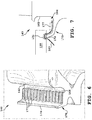
- FIG. 3 shows a perspective view of a portion of a turbine bucket 40 according to an embodiment of the invention.
- a plurality of voids 110 are disposed along an angel wing rim 74 at a distal end 78 of angel wing 70.
- Voids 110 are spaced along angel wing rim 74 such that the remaining portions of angel wing rim 74 form a plurality of column members 75.
- voids 110 are radially angled, i.e., angled with respect to a radial axis (Ar) of turbine bucket 40, although this is neither necessary nor essential. In other embodiments of the invention, voids may be substantially parallel to a radial axis of the turbine bucket.
- column members 75 include arcuate faces.
- column members 75 include a concave face 75A (a convex face of void 110) and a convex face 75B (a concave face of void 110).
- void 110 includes a first opening 110A along an axially inner surface 74A of angel wing rim 74 disposed laterally to a second opening 110B along an axially outer surface 74B of angel wing rim 74.
- column members and voids may have other shapes.
- column members and voids may include rectangular, trapezoidal, or any other cross-sectional shape.
- FIG. 5 shows a perspective view of a portion of a turbine bucket 40 according to another embodiment of the invention.
- a plurality of dam members 77 extend axially from shank portion 60 to each of the plurality of column members 75.
- dam members 77 may be angled with respect to a radial axis of turbine bucket 40, i.e., angled positively or negatively with respect to the direction of rotation of turbine bucket 40.
- dam members 77 may include one or more arcuate faces, as do column members 75, or may include rectangular, trapezoidal, or any other cross-sectional shape, such as described above.
- FIG. 6 shows a perspective view of a portion of a turbine bucket 140 according to another embodiment of the invention.
- a continuous angel wing rim 174 extends upward from angel wing seal 170 and a plurality of dam members 177 extend axially from rim 174 toward but not contacting face 162, leaving a gap 164 adjacent face 162
- FIG. 7 shows a cross-sectional side view of turbine bucket 140 of FIG. 6 with respect to a nozzle surface 130 according to an embodiment of the invention.
- nozzle surface 130 comprises or includes a porous or erodible portion along at least a radially inward surface, such that angel wing rim 174 cuts or wears a groove 131 into nozzle surface 130.
- the porous or erodible portion of nozzle surface 130 may comprise the material of nozzle surface 130 in a "honey comb" or similar pattern, such that the porous or erodible portion is subject to wear or erosion by angel wing rim 174.
- the porous or erodible portion of nozzle surface 130 may comprise or include a material that is softer than the other material(s) of nozzle surface 130, such that the porous or erodible portion is similarly subject to wear or erosion by angel wing rim 174.
- purge air 180 passes into groove 131 of nozzle surface 130 and then downward between dam members 177, toward face 162. Purge air 180 then flows circumferentially within gap 164, adjacent face 162, as turbine bucket 140 rotates, providing increased swirl to purge air 180.
- FIG. 8 shows a schematic view of purge air flow in a known turbine bucket.
- Purge air 80 is shown concentrated and having a higher swirl velocity in area 82, closer to face 62.
- FIG. 9 is a schematic view showing the effect of voids 110 on purge air 80 according to various embodiments of the invention.
- area 83 in which purge air 80 is concentrated and exhibits a higher swirl velocity is distanced further from face 62, as compared to FIG. 8 .
- This, in effect produces a curtaining effect at area 87, restricting incursion of hot gas 95 from hot gas flowpath 28 while at the same time reducing the quantity of purge air 80 escaping from wheelspace 26 into hot gas flowpath 28.
- the overall quantity of purge air needed is reduced for at least two reasons.
- Each of these reductions to the total purge air required reduces the demand on the other system components, such as the compressor from which the purge air is provided.
- angel wing rim voids may be employed on turbine buckets of any stage with similar changes to purge air swirl velocity and angle.
- Applicants have noted a very favorable result when angel wing rim voids are employed in the last stage bucket (LSB).
- Spikes in total pressure (P T ) and swirl profiles at the inner radius region of the diffuser inlet are a consequence of a mismatch between the hot gas flow and the swirl of purge air exiting the wheelspace adjacent the LSB.
- Applicants have found that angel wing rim voids according to various embodiments of the invention are capable of both increasing P T spikes at a diffuser inlet close to the inner radius while at the same time decreasing swirl spikes at or near the same location. Each of these improves diffuser performance.
- Angel wing rim voids for example, have been found to change the swirl angle of purge air exiting the LSB wheelspace by 1-3 degrees while also increasing P T spikes by 15-30%.
- FIG. 10 shows a schematic view of a LSB 140 adjacent diffuser 300.
- Hot gas 195 enters diffuser 300 at diffuser inlet plane 310 and passes toward struts 320.
- Voids according to embodiments of the invention reduce the swirl mismatch of purge air as it combines with hot gas 195, preventing separation of hot gas 195 as it enters struts 320.
- voids increase the P T spike.
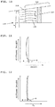
- FIG. 11 shows a graph of swirl spike as a function of diffuser inlet plane height.
- Profile A represents a swirl spike profile for a turbine having angel wing rim voids according to embodiments of the invention.
- Profile B represents a swirl spike profile for a turbine having angel wings known in the art.
- Profile A exhibits a marked decrease in swirl spike at a radially inward position of the diffuser inlet plane.
- FIG. 12 shows a graph of P T spike as a function of diffuser inlet plane height.
- Profile A represents a P T spike profile for a turbine having angel wing rim voids according to embodiments of the invention.
- Profile B represents a P T spike profile for a turbine having angel wings known in the art.
- Profile A exhibits an increase in P T spike at a radially inward position of the diffuser inlet plane.
- FIG. 13 shows a schematic cross-sectional view of a steam turbine bucket 240 having an airfoil 250 and a shank 260 affixed to a disk 290.
- a magnified view is provided of disk 290, along which voids 210 (shown in phantom) may be deployed similarly to the voids shown in the figures above.
Landscapes
- Engineering & Computer Science (AREA)
- Mechanical Engineering (AREA)
- General Engineering & Computer Science (AREA)
- Architecture (AREA)
- Turbine Rotor Nozzle Sealing (AREA)
Applications Claiming Priority (1)
| Application Number | Priority Date | Filing Date | Title |
|---|---|---|---|
| US14/603,318 US20160215625A1 (en) | 2015-01-22 | 2015-01-22 | Turbine bucket for control of wheelspace purge air |
Publications (2)
| Publication Number | Publication Date |
|---|---|
| EP3056667A2 true EP3056667A2 (de) | 2016-08-17 |
| EP3056667A3 EP3056667A3 (de) | 2017-01-18 |
Family
ID=55177891
Family Applications (1)
| Application Number | Title | Priority Date | Filing Date |
|---|---|---|---|
| EP16152213.1A Withdrawn EP3056667A3 (de) | 2015-01-22 | 2016-01-21 | Turbinenschaufel zur steuerung von radraumspülluft |
Country Status (4)
| Country | Link |
|---|---|
| US (1) | US20160215625A1 (de) |
| EP (1) | EP3056667A3 (de) |
| JP (1) | JP2016138553A (de) |
| CN (1) | CN105822353A (de) |
Families Citing this family (6)
| Publication number | Priority date | Publication date | Assignee | Title |
|---|---|---|---|---|
| US10738638B2 (en) | 2015-01-22 | 2020-08-11 | General Electric Company | Rotor blade with wheel space swirlers and method for forming a rotor blade with wheel space swirlers |
| US9631509B1 (en) * | 2015-11-20 | 2017-04-25 | Siemens Energy, Inc. | Rim seal arrangement having pumping feature |
| US20180058696A1 (en) * | 2016-08-23 | 2018-03-01 | General Electric Company | Fuel-air mixer assembly for use in a combustor of a turbine engine |
| US10683765B2 (en) * | 2017-02-14 | 2020-06-16 | General Electric Company | Turbine blades having shank features and methods of fabricating the same |
| CN108798794A (zh) * | 2018-04-24 | 2018-11-13 | 哈尔滨工程大学 | 一种具有波浪状凹陷的轮缘密封结构及使用该结构的涡轮 |
| KR102916316B1 (ko) * | 2023-09-25 | 2026-01-22 | 국방과학연구소 | 곡선형 성곽구조 형상의 가스터빈 림 씰 |
Family Cites Families (17)
| Publication number | Priority date | Publication date | Assignee | Title |
|---|---|---|---|---|
| JP4381262B2 (ja) * | 2004-09-09 | 2009-12-09 | 三菱重工業株式会社 | 動翼プラットフォーム |
| US7244104B2 (en) * | 2005-05-31 | 2007-07-17 | Pratt & Whitney Canada Corp. | Deflectors for controlling entry of fluid leakage into the working fluid flowpath of a gas turbine engine |
| US7189055B2 (en) * | 2005-05-31 | 2007-03-13 | Pratt & Whitney Canada Corp. | Coverplate deflectors for redirecting a fluid flow |
| US7465152B2 (en) * | 2005-09-16 | 2008-12-16 | General Electric Company | Angel wing seals for turbine blades and methods for selecting stator, rotor and wing seal profiles |
| US7500824B2 (en) * | 2006-08-22 | 2009-03-10 | General Electric Company | Angel wing abradable seal and sealing method |
| GB0808206D0 (en) * | 2008-05-07 | 2008-06-11 | Rolls Royce Plc | A blade arrangement |
| US8075256B2 (en) * | 2008-09-25 | 2011-12-13 | Siemens Energy, Inc. | Ingestion resistant seal assembly |
| US8419356B2 (en) * | 2008-09-25 | 2013-04-16 | Siemens Energy, Inc. | Turbine seal assembly |
| DE102009040758A1 (de) * | 2009-09-10 | 2011-03-17 | Mtu Aero Engines Gmbh | Umlenkvorrichtung für einen Leckagestrom in einer Gasturbine und Gasturbine |
| US20120163955A1 (en) * | 2010-12-23 | 2012-06-28 | General Electric Company | System and method to eliminate a hard rub and optimize a purge flow in a gas turbine |
| US8834122B2 (en) * | 2011-10-26 | 2014-09-16 | General Electric Company | Turbine bucket angel wing features for forward cavity flow control and related method |
| US20130139386A1 (en) * | 2011-12-06 | 2013-06-06 | General Electric Company | Honeycomb construction for abradable angel wing |
| US9145788B2 (en) * | 2012-01-24 | 2015-09-29 | General Electric Company | Retrofittable interstage angled seal |
| US8926283B2 (en) * | 2012-11-29 | 2015-01-06 | Siemens Aktiengesellschaft | Turbine blade angel wing with pumping features |
| US9068513B2 (en) * | 2013-01-23 | 2015-06-30 | Siemens Aktiengesellschaft | Seal assembly including grooves in an inner shroud in a gas turbine engine |
| US9181816B2 (en) * | 2013-01-23 | 2015-11-10 | Siemens Aktiengesellschaft | Seal assembly including grooves in an aft facing side of a platform in a gas turbine engine |
| US9039357B2 (en) * | 2013-01-23 | 2015-05-26 | Siemens Aktiengesellschaft | Seal assembly including grooves in a radially outwardly facing side of a platform in a gas turbine engine |
-
2015
- 2015-01-22 US US14/603,318 patent/US20160215625A1/en not_active Abandoned
-
2016
- 2016-01-15 JP JP2016005741A patent/JP2016138553A/ja active Pending
- 2016-01-21 EP EP16152213.1A patent/EP3056667A3/de not_active Withdrawn
- 2016-01-22 CN CN201610042596.0A patent/CN105822353A/zh active Pending
Non-Patent Citations (1)
| Title |
|---|
| None |
Also Published As
| Publication number | Publication date |
|---|---|
| US20160215625A1 (en) | 2016-07-28 |
| CN105822353A (zh) | 2016-08-03 |
| EP3056667A3 (de) | 2017-01-18 |
| JP2016138553A (ja) | 2016-08-04 |
Similar Documents
| Publication | Publication Date | Title |
|---|---|---|
| EP3048251B1 (de) | Turbinenschaufel zur steuerung von radraumspülluft | |
| EP3056667A2 (de) | Turbinenschaufel zur steuerung von radraumspülluft | |
| EP2948641B1 (de) | Dichtungsanordnung in einem gasturbinenmotor mit nuten in einer radial nach aussen gewandten seite einer plattform und einer nach innen gewandten seite eines innendeckbands | |
| US9260979B2 (en) | Outer rim seal assembly in a turbine engine | |
| JP6739934B2 (ja) | ガスタービンのシール | |
| US9145788B2 (en) | Retrofittable interstage angled seal | |
| JP6888907B2 (ja) | ガスタービン | |
| US8561997B2 (en) | Adverse pressure gradient seal mechanism | |
| US10619484B2 (en) | Turbine bucket cooling | |
| JP6742753B2 (ja) | 侵入損失を制御するためのタービンバケットプラットフォーム | |
| EP3048249B1 (de) | Turbinenschaufel zur steuerung von radraumspülluft | |
| US10544695B2 (en) | Turbine bucket for control of wheelspace purge air | |
| US10815808B2 (en) | Turbine bucket cooling | |
| EP3273004B1 (de) | Turbinenschaufelkühlung | |
| JP6986426B2 (ja) | タービン |
Legal Events
| Date | Code | Title | Description |
|---|---|---|---|
| PUAI | Public reference made under article 153(3) epc to a published international application that has entered the european phase |
Free format text: ORIGINAL CODE: 0009012 |
|
| AK | Designated contracting states |
Kind code of ref document: A2 Designated state(s): AL AT BE BG CH CY CZ DE DK EE ES FI FR GB GR HR HU IE IS IT LI LT LU LV MC MK MT NL NO PL PT RO RS SE SI SK SM TR |
|
| AX | Request for extension of the european patent |
Extension state: BA ME |
|
| PUAL | Search report despatched |
Free format text: ORIGINAL CODE: 0009013 |
|
| AK | Designated contracting states |
Kind code of ref document: A3 Designated state(s): AL AT BE BG CH CY CZ DE DK EE ES FI FR GB GR HR HU IE IS IT LI LT LU LV MC MK MT NL NO PL PT RO RS SE SI SK SM TR |
|
| AX | Request for extension of the european patent |
Extension state: BA ME |
|
| RIC1 | Information provided on ipc code assigned before grant |
Ipc: F01D 5/08 20060101AFI20161215BHEP Ipc: F01D 5/14 20060101ALI20161215BHEP Ipc: F01D 11/00 20060101ALI20161215BHEP Ipc: F01D 11/02 20060101ALI20161215BHEP |
|
| 17P | Request for examination filed |
Effective date: 20170718 |
|
| RBV | Designated contracting states (corrected) |
Designated state(s): AL AT BE BG CH CY CZ DE DK EE ES FI FR GB GR HR HU IE IS IT LI LT LU LV MC MK MT NL NO PL PT RO RS SE SI SK SM TR |
|
| 17Q | First examination report despatched |
Effective date: 20180626 |
|
| STAA | Information on the status of an ep patent application or granted ep patent |
Free format text: STATUS: THE APPLICATION IS DEEMED TO BE WITHDRAWN |
|
| 18D | Application deemed to be withdrawn |
Effective date: 20190801 |