EP3056739B1 - Soupape de purge de type à chemise, actionnée par deux pressions de contrôle agissant sur un piston - Google Patents
Soupape de purge de type à chemise, actionnée par deux pressions de contrôle agissant sur un piston Download PDFInfo
- Publication number
- EP3056739B1 EP3056739B1 EP16155234.4A EP16155234A EP3056739B1 EP 3056739 B1 EP3056739 B1 EP 3056739B1 EP 16155234 A EP16155234 A EP 16155234A EP 3056739 B1 EP3056739 B1 EP 3056739B1
- Authority
- EP
- European Patent Office
- Prior art keywords
- pressure
- piston
- pressure chamber
- valve
- bleed valve
- Prior art date
- Legal status (The legal status is an assumption and is not a legal conclusion. Google has not performed a legal analysis and makes no representation as to the accuracy of the status listed.)
- Active
Links
Images

Classifications
-
- F—MECHANICAL ENGINEERING; LIGHTING; HEATING; WEAPONS; BLASTING
- F02—COMBUSTION ENGINES; HOT-GAS OR COMBUSTION-PRODUCT ENGINE PLANTS
- F02C—GAS-TURBINE PLANTS; AIR INTAKES FOR JET-PROPULSION PLANTS; CONTROLLING FUEL SUPPLY IN AIR-BREATHING JET-PROPULSION PLANTS
- F02C9/00—Controlling gas-turbine plants; Controlling fuel supply in air- breathing jet-propulsion plants
- F02C9/16—Control of working fluid flow
- F02C9/18—Control of working fluid flow by bleeding, bypassing or acting on variable working fluid interconnections between turbines or compressors or their stages
-
- F—MECHANICAL ENGINEERING; LIGHTING; HEATING; WEAPONS; BLASTING
- F04—POSITIVE - DISPLACEMENT MACHINES FOR LIQUIDS; PUMPS FOR LIQUIDS OR ELASTIC FLUIDS
- F04D—NON-POSITIVE-DISPLACEMENT PUMPS
- F04D27/00—Control, e.g. regulation, of pumps, pumping installations or pumping systems specially adapted for elastic fluids
- F04D27/02—Surge control
- F04D27/0207—Surge control by bleeding, bypassing or recycling fluids
- F04D27/0215—Arrangements therefor, e.g. bleed or by-pass valves
-
- F—MECHANICAL ENGINEERING; LIGHTING; HEATING; WEAPONS; BLASTING
- F01—MACHINES OR ENGINES IN GENERAL; ENGINE PLANTS IN GENERAL; STEAM ENGINES
- F01D—NON-POSITIVE DISPLACEMENT MACHINES OR ENGINES, e.g. STEAM TURBINES
- F01D17/00—Regulating or controlling by varying flow
- F01D17/10—Final actuators
- F01D17/105—Final actuators by passing part of the fluid
-
- F—MECHANICAL ENGINEERING; LIGHTING; HEATING; WEAPONS; BLASTING
- F01—MACHINES OR ENGINES IN GENERAL; ENGINE PLANTS IN GENERAL; STEAM ENGINES
- F01D—NON-POSITIVE DISPLACEMENT MACHINES OR ENGINES, e.g. STEAM TURBINES
- F01D17/00—Regulating or controlling by varying flow
- F01D17/20—Devices dealing with sensing elements or final actuators or transmitting means between them, e.g. power-assisted
- F01D17/22—Devices dealing with sensing elements or final actuators or transmitting means between them, e.g. power-assisted the operation or power assistance being predominantly non-mechanical
- F01D17/26—Devices dealing with sensing elements or final actuators or transmitting means between them, e.g. power-assisted the operation or power assistance being predominantly non-mechanical fluid, e.g. hydraulic
-
- F—MECHANICAL ENGINEERING; LIGHTING; HEATING; WEAPONS; BLASTING
- F04—POSITIVE - DISPLACEMENT MACHINES FOR LIQUIDS; PUMPS FOR LIQUIDS OR ELASTIC FLUIDS
- F04D—NON-POSITIVE-DISPLACEMENT PUMPS
- F04D27/00—Control, e.g. regulation, of pumps, pumping installations or pumping systems specially adapted for elastic fluids
- F04D27/02—Surge control
- F04D27/0207—Surge control by bleeding, bypassing or recycling fluids
- F04D27/023—Details or means for fluid extraction
-
- F—MECHANICAL ENGINEERING; LIGHTING; HEATING; WEAPONS; BLASTING
- F16—ENGINEERING ELEMENTS AND UNITS; GENERAL MEASURES FOR PRODUCING AND MAINTAINING EFFECTIVE FUNCTIONING OF MACHINES OR INSTALLATIONS; THERMAL INSULATION IN GENERAL
- F16K—VALVES; TAPS; COCKS; ACTUATING-FLOATS; DEVICES FOR VENTING OR AERATING
- F16K1/00—Lift valves or globe valves, i.e. cut-off apparatus with closure members having at least a component of their opening and closing motion perpendicular to the closing faces
- F16K1/12—Lift valves or globe valves, i.e. cut-off apparatus with closure members having at least a component of their opening and closing motion perpendicular to the closing faces with streamlined valve member around which the fluid flows when the valve is opened
- F16K1/126—Lift valves or globe valves, i.e. cut-off apparatus with closure members having at least a component of their opening and closing motion perpendicular to the closing faces with streamlined valve member around which the fluid flows when the valve is opened actuated by fluid
-
- F—MECHANICAL ENGINEERING; LIGHTING; HEATING; WEAPONS; BLASTING
- F16—ENGINEERING ELEMENTS AND UNITS; GENERAL MEASURES FOR PRODUCING AND MAINTAINING EFFECTIVE FUNCTIONING OF MACHINES OR INSTALLATIONS; THERMAL INSULATION IN GENERAL
- F16K—VALVES; TAPS; COCKS; ACTUATING-FLOATS; DEVICES FOR VENTING OR AERATING
- F16K3/00—Gate valves or sliding valves, i.e. cut-off apparatus with closing members having a sliding movement along the seat for opening and closing
- F16K3/02—Gate valves or sliding valves, i.e. cut-off apparatus with closing members having a sliding movement along the seat for opening and closing with flat sealing faces; Packings therefor
- F16K3/0218—Gate valves or sliding valves, i.e. cut-off apparatus with closing members having a sliding movement along the seat for opening and closing with flat sealing faces; Packings therefor with only one sealing face
-
- F—MECHANICAL ENGINEERING; LIGHTING; HEATING; WEAPONS; BLASTING
- F16—ENGINEERING ELEMENTS AND UNITS; GENERAL MEASURES FOR PRODUCING AND MAINTAINING EFFECTIVE FUNCTIONING OF MACHINES OR INSTALLATIONS; THERMAL INSULATION IN GENERAL
- F16K—VALVES; TAPS; COCKS; ACTUATING-FLOATS; DEVICES FOR VENTING OR AERATING
- F16K3/00—Gate valves or sliding valves, i.e. cut-off apparatus with closing members having a sliding movement along the seat for opening and closing
- F16K3/02—Gate valves or sliding valves, i.e. cut-off apparatus with closing members having a sliding movement along the seat for opening and closing with flat sealing faces; Packings therefor
- F16K3/0254—Gate valves or sliding valves, i.e. cut-off apparatus with closing members having a sliding movement along the seat for opening and closing with flat sealing faces; Packings therefor being operated by particular means
-
- F—MECHANICAL ENGINEERING; LIGHTING; HEATING; WEAPONS; BLASTING
- F16—ENGINEERING ELEMENTS AND UNITS; GENERAL MEASURES FOR PRODUCING AND MAINTAINING EFFECTIVE FUNCTIONING OF MACHINES OR INSTALLATIONS; THERMAL INSULATION IN GENERAL
- F16K—VALVES; TAPS; COCKS; ACTUATING-FLOATS; DEVICES FOR VENTING OR AERATING
- F16K31/00—Actuating devices; Operating means; Releasing devices
- F16K31/02—Actuating devices; Operating means; Releasing devices electric; magnetic
- F16K31/06—Actuating devices; Operating means; Releasing devices electric; magnetic using a magnet, e.g. diaphragm valves, cutting off by means of a liquid
- F16K31/0644—One-way valve
- F16K31/0668—Sliding valves
-
- F—MECHANICAL ENGINEERING; LIGHTING; HEATING; WEAPONS; BLASTING
- F16—ENGINEERING ELEMENTS AND UNITS; GENERAL MEASURES FOR PRODUCING AND MAINTAINING EFFECTIVE FUNCTIONING OF MACHINES OR INSTALLATIONS; THERMAL INSULATION IN GENERAL
- F16K—VALVES; TAPS; COCKS; ACTUATING-FLOATS; DEVICES FOR VENTING OR AERATING
- F16K31/00—Actuating devices; Operating means; Releasing devices
- F16K31/12—Actuating devices; Operating means; Releasing devices actuated by fluid
- F16K31/122—Actuating devices; Operating means; Releasing devices actuated by fluid the fluid acting on a piston
-
- F—MECHANICAL ENGINEERING; LIGHTING; HEATING; WEAPONS; BLASTING
- F16—ENGINEERING ELEMENTS AND UNITS; GENERAL MEASURES FOR PRODUCING AND MAINTAINING EFFECTIVE FUNCTIONING OF MACHINES OR INSTALLATIONS; THERMAL INSULATION IN GENERAL
- F16K—VALVES; TAPS; COCKS; ACTUATING-FLOATS; DEVICES FOR VENTING OR AERATING
- F16K31/00—Actuating devices; Operating means; Releasing devices
- F16K31/12—Actuating devices; Operating means; Releasing devices actuated by fluid
- F16K31/122—Actuating devices; Operating means; Releasing devices actuated by fluid the fluid acting on a piston
- F16K31/124—Actuating devices; Operating means; Releasing devices actuated by fluid the fluid acting on a piston servo actuated
-
- Y—GENERAL TAGGING OF NEW TECHNOLOGICAL DEVELOPMENTS; GENERAL TAGGING OF CROSS-SECTIONAL TECHNOLOGIES SPANNING OVER SEVERAL SECTIONS OF THE IPC; TECHNICAL SUBJECTS COVERED BY FORMER USPC CROSS-REFERENCE ART COLLECTIONS [XRACs] AND DIGESTS
- Y10—TECHNICAL SUBJECTS COVERED BY FORMER USPC
- Y10T—TECHNICAL SUBJECTS COVERED BY FORMER US CLASSIFICATION
- Y10T137/00—Fluid handling
- Y10T137/3367—Larner-Johnson type valves; i.e., telescoping internal valve in expanded flow line section
Definitions
- the present disclosure relates to valves, and more particularly to valves used in bleed systems such as those used in gas turbine engines.
- the present invention provides a bleed valve for a turbomachine that includes a housing body, wherein the housing body comprises an inner diameter portion and an outer diameter portion, wherein, in use, high-pressure fluid flows therebetween, and wherein the housing body comprises an inlet housing and an outlet housing, wherein the outlet housing is downstream of the inlet housing, and a hollow shaft defining a valve axis.
- the hollow shaft includes a first end mounted to an inner diameter portion of the inlet housing and a second end mounted to an end cap of an inner diameter portion of the outlet housing, wherein the hollow shaft comprises a shaft passage.
- the bleed valve also includes a full-area piston slidably mounted to the shaft between the inlet housing and the end cap for movement between an open and a closed position.
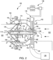
- a partial view of an exemplary embodiment of a bleed valve constructed in accordance with the disclosure is shown in Fig. 1 and is designated generally by reference character 100.
- full-area piston configuration described above provides a more light weight, compact and controllable bleed valve, as compared with a half-area piston configuration, that reliably operates at elevated temperature and pressure. Additionally, the symmetric configuration found in full-area piston 116 provides an optimum configuration for high vibration environment over traditional half-area bleed valves that tend to include asymmetries and have a cantilevered configuration.
- Seal ring 146 minimizes leakage of high-pressure air to first pressure chamber 118, e.g. the intermediate pressure chamber. Additionally, bleed valve 100 does not include any external leakage of high-pressure fluid from high-pressure seal ring 146 to first pressure chamber 118. This lack of external leakage creates an overall more efficient bleed valve 100, as compared to half-area designs, where leakage of high-pressure fluid into an ambient chamber is wasted.
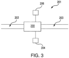
- a high-pressure bleed valve system 201 for a gas turbine engine includes a valve 200, similar to valve 100, mounted within a high-pressure bleed duct 203 of a gas turbine engine.
- System 201 includes a solenoid pressure valve 206 and an intermediate-pressure source 204.
- Solenoid pressure valve 206 is in fluid communication with the solenoid pressure chamber, e.g. second pressure chamber 124, for controlling the pressure in solenoid pressure chamber 124.
- Intermediate-pressure source 204 is in fluid communication with the intermediate-pressure chamber, e.g. first pressure chamber 118. It is contemplated that intermediate-pressure source 204 can be from an intermediate stage of the compressor, for example, a stage from the low-pressure compressor.
- a method for controlling pressure within a gas turbine compressor stage includes moving a piston, e.g. piston 116, into an open position such that high-pressure fluid is free to flow through a housing body, e.g. inlet and outlet housings 102 and 104, respectively, and supplying intermediate-pressure fluid to a first fluid chamber, e.g. first chamber 118.
- the first fluid chamber is in fluid communication with an upstream surface, e.g. upstream surface 132, of the piston, thereby moving the piston into a closed position.
- the method also includes supplying fluid pressure from a solenoid pressure valve, e.g. solenoid pressure valve 206, when the solenoid pressure valve is energized, into a second fluid chamber, e.g. second fluid chamber 124, in fluid communication with a downstream surface, e.g. downstream surface 134, of piston, thereby moving said piston into an open position.
- the method includes passing high-pressure fluid through the housing body while piston 116 is in the open position for a desired time and removing fluid pressure from the second fluid chamber, e.g. when the solenoid valve is de-energized, thereby causing a force imbalance between the upstream and downstream surfaces allowing the piston to return to the closed position.
Landscapes
- Engineering & Computer Science (AREA)
- General Engineering & Computer Science (AREA)
- Mechanical Engineering (AREA)
- Life Sciences & Earth Sciences (AREA)
- Sustainable Development (AREA)
- Physics & Mathematics (AREA)
- Fluid Mechanics (AREA)
- Chemical & Material Sciences (AREA)
- Combustion & Propulsion (AREA)
- Fluid-Driven Valves (AREA)
Claims (10)
- Soupape de purge (100) pour turbomachine comprenant :un corps de boîtier, dans laquelle le corps de boîtier comprend une partie de diamètre interne et une partie de diamètre externe, dans laquelle, en utilisation, un fluide à haute pression s'écoule entre elles, et dans laquelle le corps de boîtier comprend un boîtier d'entrée (102) et un boîtier de sortie (104), dans laquelle le boîtier de sortie est en aval du boîtier d'entrée (102) ;un arbre creux (106) définissant un axe de soupape (A) ayant une première extrémité (108) montée sur une partie de diamètre interne (112) du boîtier d'entrée (102) et une seconde extrémité (110) montée sur un capuchon d'extrémité (114) d'une partie de diamètre interne du boîtier de sortie (104), dans laquelle l'arbre creux comprend un passage d'arbre (117) ;un piston sur toute la surface (116) monté de manière à coulisser sur l'arbre creux (106) entre le boîtier d'entrée (102) et le capuchon d'extrémité (114) pour un mouvement entre une position ouverte et une position fermée ;une première chambre de pression (118) définie entre un côté amont (120) du piston (116) et la partie de diamètre interne (112) du boîtier d'entrée (102) en communication fluidique avec un orifice de pression intermédiaire (122) ; etune seconde chambre de pression (124) définie entre un côté aval (126) du piston (116) et le capuchon d'extrémité (114) en communication fluidique avec un orifice de pression de solénoïde (130) à travers le passage d'arbre (117), dans laquelle une zone d'une surface amont (132) du piston (116) faisant un angle par rapport à l'axe de soupape (A) et en communication fluidique avec la première chambre de pression (118) est sensiblement égale à une zone d'une surface aval (134) du piston (116) faisant un angle par rapport à l'axe de la soupape (A) et en communication fluidique avec la seconde chambre de pression (124) ;dans lequel l'orifice de pression de solénoïde (130) est configuré pour se connecter à une électrovanne de pression (138) qui contrôle la pression dans la seconde chambre de pression (124),caractérisée en ce quel'orifice de pression de solénoïde (130) fait partie du boîtier d'entrée (102) ;et en ce que, dans une position ouverte, une partie d'extrémité conique (162) d'une chemise externe (142) du piston (116) forme une surface sensiblement conique (164) en liaison avec le capuchon d'extrémité (114).
- Soupape de purge selon la revendication 1, dans laquelle l'orifice de pression intermédiaire (122) est configuré pour se connecter à une source de pression intermédiaire (136).
- Soupape de purge selon la revendication 1 ou la revendication 2, dans laquelle une pression intermédiaire de la première chambre de pression (118) est destinée à entraîner le piston (116) dans la position fermée et une pression de solénoïde de la seconde chambre de pression (124) est destinée à entraîner le piston (116) dans la position ouverte.
- Soupape de purge selon une quelconque revendication précédente, dans laquelle le piston (116) comprend des chemises interne et externe (140, 142) et une partie conique (144) les reliant, dans laquelle la partie conique (144) converge dans une direction aval.
- Soupape de purge selon la revendication 4, dans laquelle la chemise externe (142) du piston (116) comprend une bague d'étanchéité haute pression (146) au niveau d'une interface entre une surface de diamètre externe (148) de la chemise externe (142) du piston (116) et une surface de diamètre interne (150) du boîtier d'entrée (102).
- Soupape de purge selon la revendication 4 ou la revendication 5, dans laquelle le capuchon d'extrémité (114) comprend une bague d'étanchéité (152) au niveau d'une interface entre une surface de diamètre externe (154) du capuchon d'extrémité (114) et une surface de diamètre interne (156) de la chemise externe (142) du piston (116).
- Soupape de purge selon une quelconque revendication précédente, comprenant en outre un ressort (158) positionné à l'intérieur de la première chambre de pression (118).
- Soupape de purge selon une quelconque revendication précédente, dans laquelle un côté aval (166) de la partie de diamètre interne (112) du boîtier d'entrée (102) est à proximité d'un côté amont (170) du capuchon d'extrémité (114).
- Système de soupape de purge (201) pour un moteur à turbine à gaz, comprenant :la soupape de purge selon une quelconque revendication précédente ;une électrovanne de pression (206) en communication fluidique avec la chambre de pression de solénoïde (124) pour contrôler la pression dans la chambre de pression de solénoïde (124) ; etune source de pression intermédiaire (204) en communication fluidique avec la chambre à pression intermédiaire (118), dans lequel une pression intermédiaire de la chambre à pression intermédiaire (118) est destinée à entraîner un piston de la soupape (200) dans une position fermée et une pression de solénoïde de la chambre de pression de solénoïde (124) est destinée à entraîner le piston dans une position ouverte.
- Compresseur pour un moteur à turbine à gaz doté d'un système de soupape de purge selon la revendication 9, dans lequel la source de pression intermédiaire (204) est un étage intermédiaire du compresseur.
Applications Claiming Priority (1)
| Application Number | Priority Date | Filing Date | Title |
|---|---|---|---|
| US14/622,521 US9689315B2 (en) | 2015-02-13 | 2015-02-13 | Full-area bleed valves |
Publications (2)
| Publication Number | Publication Date |
|---|---|
| EP3056739A1 EP3056739A1 (fr) | 2016-08-17 |
| EP3056739B1 true EP3056739B1 (fr) | 2024-06-12 |
Family
ID=55353075
Family Applications (1)
| Application Number | Title | Priority Date | Filing Date |
|---|---|---|---|
| EP16155234.4A Active EP3056739B1 (fr) | 2015-02-13 | 2016-02-11 | Soupape de purge de type à chemise, actionnée par deux pressions de contrôle agissant sur un piston |
Country Status (2)
| Country | Link |
|---|---|
| US (1) | US9689315B2 (fr) |
| EP (1) | EP3056739B1 (fr) |
Families Citing this family (32)
| Publication number | Priority date | Publication date | Assignee | Title |
|---|---|---|---|---|
| CA2975264C (fr) * | 2015-02-16 | 2023-08-22 | Dukes Aerospace, Inc. | Systeme de soupape redondant |
| US9784184B2 (en) * | 2015-03-16 | 2017-10-10 | Hamilton Sundstrand Corporation | Self-actuated, in-line bleed valve |
| CA3018212C (fr) * | 2016-03-23 | 2021-10-12 | Dukes Aerospace, Inc. | Compensation de pression d'entree pour systeme de soupape |
| PT3449331T (pt) | 2016-04-26 | 2020-02-03 | Oxford Flow Ltd | Dispositivo para controlar o escoamento de um fluido |
| US10180106B2 (en) * | 2016-05-17 | 2019-01-15 | Hamilton Sundstrand Corporation | Solenoids for gas turbine engine bleed valves |
| CN106286954A (zh) * | 2016-09-29 | 2017-01-04 | 黄建斌 | 管道自流体调节阀及执行装置 |
| US10458337B2 (en) | 2017-01-20 | 2019-10-29 | Hamilton Sundstrand Corporation | Dual inline valve with manual override |
| US10519864B2 (en) | 2017-01-20 | 2019-12-31 | Hamilton Sundstrand Corporation | Dual inline starter air valve |
| US9957899B1 (en) * | 2017-01-20 | 2018-05-01 | Hamilton Sundstrand Corporation | Dual inline starter air valve |
| WO2019104051A1 (fr) * | 2017-11-21 | 2019-05-31 | Dukes Aerospace, Inc. | Système de soupape à clapet et procédé |
| US10428971B1 (en) | 2018-03-06 | 2019-10-01 | Hamilton Sundstrand Corporation | Inline air valve nose cap for reduced contamination |
| US10513977B2 (en) | 2018-03-06 | 2019-12-24 | Hamilton Sundstrand Corporation | Adjustable snap action passive inline air valve |
| US10473225B2 (en) | 2018-03-29 | 2019-11-12 | Hamilton Sundstrand Corporation | Passive valve |
| FR3079875B1 (fr) * | 2018-04-05 | 2021-04-30 | Safran Aircraft Engines | Dispositif de decharge de turbomachine comportant une vanne |
| FR3080430B1 (fr) * | 2018-04-18 | 2021-01-22 | Safran Aircraft Engines | Vanne de decharge coudee a ouverture regulee |
| US11053949B2 (en) * | 2018-08-03 | 2021-07-06 | Hamilton Sundstrand Corporation | Passively controlled inline bleed valves |
| US10975875B2 (en) | 2018-08-03 | 2021-04-13 | Hamilton Sundstrand Corporation | Passive bleed valves with adjustable pressure threshold |
| US10578215B2 (en) * | 2018-08-06 | 2020-03-03 | Hans D. Baumann | Inline high-recovery flow control valve |
| US10626802B2 (en) * | 2018-09-21 | 2020-04-21 | United Technologies Corporation | Ducted gas turbine engine stability bleed valve with passive and active shutoff |
| US10865715B2 (en) * | 2018-12-07 | 2020-12-15 | Raytheon Technologies Corporation | Passive stability bleed valve with adjustable reference pressure regulator and remote override capability |
| EP3726032B1 (fr) | 2019-04-17 | 2023-09-13 | Microtecnica S.r.l. | Soupape de purge |
| US10823087B1 (en) | 2019-06-20 | 2020-11-03 | Hamilton Sunstrand Corporation | Inline valves, gas turbine engines with inline bleed valves, and methods controlling flow through inline valves |
| US10830372B1 (en) * | 2019-06-20 | 2020-11-10 | Hamilton Sunstrand Corporation | Pneumatic controllers, pneumatically controlled inline valves, and methods of cooling pneumatic controllers |
| US10823308B1 (en) * | 2019-06-20 | 2020-11-03 | Hamilton Sunstrand Corporation | Controllers for inline valves, inline valves, and methods of controlling flow through inline valves |
| US10824172B1 (en) | 2019-06-20 | 2020-11-03 | Hamilton Sunstrand Corporation | Pneumatic controllers, pneumatically controlled inline valves, and methods of actuating inline valves |
| CN110645364A (zh) * | 2019-10-11 | 2020-01-03 | 上海胜风流体机械有限公司 | 一种电磁气动放空阀 |
| CN114458455B (zh) * | 2021-12-27 | 2023-10-24 | 中国航发长春控制科技有限公司 | 一种高可靠性耐高温高压的动密封结构 |
| US11906063B2 (en) | 2022-01-21 | 2024-02-20 | Hamilton Sundstrand Corporation | Pressure actuated switching valve |
| US11939874B2 (en) * | 2022-06-02 | 2024-03-26 | Pratt & Whitney Canada Corp. | Switching valve |
| US11906071B1 (en) | 2022-08-26 | 2024-02-20 | Hamilton Sundstrand Corporation | Remote passively and actively actuated valve systems |
| CN115711162B (zh) * | 2022-11-01 | 2025-04-08 | 山东齐鲁电机制造有限公司 | 一种汽轮机紧凑型主汽阀 |
| CN117006259B (zh) * | 2023-09-13 | 2025-10-28 | 上海齐宇机电设备有限公司 | 管道截止阀 |
Citations (3)
| Publication number | Priority date | Publication date | Assignee | Title |
|---|---|---|---|---|
| DE456023C (de) * | 1928-02-14 | Pelton Water Wheel Company | In der Rohrachse angeordneter, hydraulisch gesteuerter, becherfoermig gestalteter Rohrschieber | |
| US1752439A (en) * | 1926-10-14 | 1930-04-01 | I P Morris And De La Vergne In | Sleeve valve |
| US3092132A (en) * | 1961-05-15 | 1963-06-04 | Rotax Ltd | Compressed air or other gas control valves |
Family Cites Families (62)
| Publication number | Priority date | Publication date | Assignee | Title |
|---|---|---|---|---|
| US3124115A (en) * | 1964-03-10 | Voorhies | ||
| US1524400A (en) * | 1919-11-25 | 1925-01-27 | William Cramp & Sons Ship & En | Valve structure |
| US1750417A (en) * | 1928-01-31 | 1930-03-11 | Leslie N Mcclellan | Pressure-actuated control valve |
| US2297082A (en) * | 1940-12-13 | 1942-09-29 | Grover J Hornsby | Valve |
| US2919714A (en) * | 1958-01-03 | 1960-01-05 | United Aircraft Corp | Pressure balanced regulating and shut-off valve |
| US2950732A (en) * | 1958-09-11 | 1960-08-30 | Rotax Ltd | Compressed air or other gas control valves |
| US3076471A (en) * | 1959-05-25 | 1963-02-05 | Vapor Heating Corp | Modulating in-line valve |
| GB1007138A (en) * | 1961-01-10 | 1965-10-13 | Plessey Co Ltd | Improvements in or relating to fluid flow control valves |
| US3172420A (en) * | 1961-05-18 | 1965-03-09 | Schulz Tool & Mfg Co | Liquid flow control system and by-pass valve |
| US3156253A (en) * | 1961-11-24 | 1964-11-10 | Gen Electric | Pressure regulating valve and combination on-off valve |
| US3198204A (en) * | 1963-05-08 | 1965-08-03 | Vapor Corp | Inline valve |
| US3338259A (en) * | 1964-01-24 | 1967-08-29 | Plessey Uk Ltd | Automatic regulating valves |
| US3297047A (en) * | 1964-03-17 | 1967-01-10 | Vapor Corp | Valve assembly |
| GB1113236A (en) * | 1964-11-04 | 1968-05-08 | Plessey Uk Ltd | Improvements in or relating to pneumatically operated servo-control devices for valves |
| US3380469A (en) * | 1965-07-16 | 1968-04-30 | Vapor Corp | Valve assembly |
| US3307786A (en) * | 1965-09-17 | 1967-03-07 | Vapor Corp | Modulating inline valve |
| US3415269A (en) * | 1967-01-24 | 1968-12-10 | Vapor Corp | Multiple positioned pilot controlled poppet valve |
| US3521661A (en) * | 1967-07-28 | 1970-07-28 | Stewart Warner Corp | Hot gas valve |
| GB1243054A (en) * | 1968-01-22 | 1971-08-18 | Rotax Ltd | Fluid flow controlling valves |
| US3540464A (en) * | 1968-03-04 | 1970-11-17 | Avco Corp | Flow control valves |
| US3515165A (en) * | 1968-10-16 | 1970-06-02 | Vapor Corp | Pressure regulator |
| US3566907A (en) * | 1969-04-25 | 1971-03-02 | Vapor Corp | Inline valve position indicator |
| US3586033A (en) * | 1969-07-07 | 1971-06-22 | Schulz Tool & Mfg Co | Combined aerial refueling coupling and pressure regulator |
| US3586458A (en) * | 1969-09-16 | 1971-06-22 | Avco Corp | Bleed control actuator for gas turbine engine |
| US3632223A (en) * | 1969-09-30 | 1972-01-04 | Gen Electric | Turbine engine having multistage compressor with interstage bleed air system |
| GB1371898A (en) * | 1970-11-20 | 1974-10-30 | Normalair Garrett Ltd | Control means for fluid flow valves |
| US3655134A (en) * | 1970-11-23 | 1972-04-11 | Hobson Ltd H M | Jet engines for aircraft |
| US3777489A (en) * | 1972-06-01 | 1973-12-11 | Gen Electric | Combustor casing and concentric air bleed structure |
| US3865128A (en) * | 1972-09-08 | 1975-02-11 | Vijay K Zadoo | Pressure regulating and shut-off valve |
| US3818921A (en) * | 1972-09-15 | 1974-06-25 | Bendix Corp | Fluid flow throttling valve |
| US3792713A (en) * | 1973-05-21 | 1974-02-19 | Vapor Corp | Pressure regulator with flow limiter |
| US3825026A (en) * | 1973-06-01 | 1974-07-23 | Vapor Corp | Inline valve |
| US3792716A (en) * | 1973-06-13 | 1974-02-19 | Vapor Corp | Inline valve with reverse pressure closing means |
| US3849020A (en) * | 1973-09-13 | 1974-11-19 | Bendix Corp | Fluidic compressor air bleed valve control apparatus |
| US3915587A (en) * | 1973-09-27 | 1975-10-28 | United Technologies Corp | Variable size bleed port for jet engines |
| US3945759A (en) * | 1974-10-29 | 1976-03-23 | General Electric Company | Bleed air manifold |
| DE2519376C2 (de) * | 1975-04-30 | 1983-09-22 | Kraftwerk Union AG, 4330 Mülheim | Steuerbares Ventil für eine Frischdampfleitung einer Kernreaktoranlage |
| US4280678A (en) * | 1978-11-29 | 1981-07-28 | Pratt & Whitney Aircraft Of Canada, Limited | Bleed valve |
| US4373544A (en) * | 1980-09-25 | 1983-02-15 | United Technologies Corporation | Check valve |
| US4640091A (en) * | 1984-01-27 | 1987-02-03 | Pratt & Whitney Canada Inc. | Apparatus for improving acceleration in a multi-shaft gas turbine engine |
| US4610265A (en) | 1984-12-12 | 1986-09-09 | Sundstrand Corporation | Turbine compressor stall recovery valve |
| US5174545A (en) * | 1991-09-26 | 1992-12-29 | Pratt & Whitney Canada, Inc. | Contamination resistant bleed valve |
| FR2692332B1 (fr) * | 1992-06-12 | 1994-08-05 | Legris Sa | Vanne pilotee. |
| US5487527A (en) * | 1994-06-02 | 1996-01-30 | Fisher Controls International, Inc. | Valve actuator |
| US5540252A (en) * | 1994-07-21 | 1996-07-30 | United Technologies Corporation | Pneumatically stabilized inline valve |
| ES2198499T3 (es) * | 1995-10-19 | 2004-02-01 | C Valves Ltd. | Valvulas de control en linea. |
| US6752168B1 (en) * | 1999-11-10 | 2004-06-22 | Aker Maritime Asa | System for controlling the working conditions for mechanical pumps, and a regulation valve for such a system |
| US6742539B2 (en) * | 2000-05-24 | 2004-06-01 | Innovative Controls | Co-axial control valve |
| US6446657B1 (en) | 2000-12-15 | 2002-09-10 | Fairchild Controls Corporation | Aircraft air control valve apparatus |
| JP3995543B2 (ja) * | 2002-07-03 | 2007-10-24 | 旭有機材工業株式会社 | 流体制御弁 |
| US6981842B2 (en) | 2003-07-22 | 2006-01-03 | Honeywell International, Inc. | Bleed valve system |
| US7434405B2 (en) * | 2005-05-31 | 2008-10-14 | United Technologies Corporation | Bleed diffuser for gas turbine engine |
| JP2007058352A (ja) * | 2005-08-22 | 2007-03-08 | Asahi Organic Chem Ind Co Ltd | 流体制御装置 |
| US7387489B2 (en) * | 2005-10-17 | 2008-06-17 | Honeywell International Inc. | Bleed valve outlet flow deflector |
| US20090078828A1 (en) * | 2007-09-25 | 2009-03-26 | Honeywell International, Inc. | Anti-ice valve components and methods of coupling a valve assembly to a servo controller of anti-ice valve components |
| US20100107594A1 (en) * | 2008-10-31 | 2010-05-06 | General Electric Company | Turbine integrated bleed system and method for a gas turbine engine |
| HRP20130875T1 (hr) * | 2009-05-20 | 2013-10-25 | HYDROMAT-INŽENJERING d.o.o. | Regulacijski ventil s hidrauliäśnim aksijalnim klipom i njegova primjena |
| US8567758B2 (en) * | 2010-08-18 | 2013-10-29 | Agco Corporation | Double solenoid valve |
| US20120045317A1 (en) * | 2010-08-23 | 2012-02-23 | Honeywell International Inc. | Fuel actuated bleed air system |
| US8661833B2 (en) * | 2011-01-14 | 2014-03-04 | Hamilton Sundstrand Corporation | Bleed valve module |
| US20130104516A1 (en) * | 2011-10-31 | 2013-05-02 | General Electric Company | Method of monitoring an operation of a compressor bleed valve |
| US8967528B2 (en) * | 2012-01-24 | 2015-03-03 | The Boeing Company | Bleed air systems for use with aircrafts and related methods |
-
2015
- 2015-02-13 US US14/622,521 patent/US9689315B2/en active Active
-
2016
- 2016-02-11 EP EP16155234.4A patent/EP3056739B1/fr active Active
Patent Citations (3)
| Publication number | Priority date | Publication date | Assignee | Title |
|---|---|---|---|---|
| DE456023C (de) * | 1928-02-14 | Pelton Water Wheel Company | In der Rohrachse angeordneter, hydraulisch gesteuerter, becherfoermig gestalteter Rohrschieber | |
| US1752439A (en) * | 1926-10-14 | 1930-04-01 | I P Morris And De La Vergne In | Sleeve valve |
| US3092132A (en) * | 1961-05-15 | 1963-06-04 | Rotax Ltd | Compressed air or other gas control valves |
Also Published As
| Publication number | Publication date |
|---|---|
| EP3056739A1 (fr) | 2016-08-17 |
| US9689315B2 (en) | 2017-06-27 |
| US20160237913A1 (en) | 2016-08-18 |
Similar Documents
| Publication | Publication Date | Title |
|---|---|---|
| EP3056739B1 (fr) | Soupape de purge de type à chemise, actionnée par deux pressions de contrôle agissant sur un piston | |
| US3865128A (en) | Pressure regulating and shut-off valve | |
| EP2373910B1 (fr) | Vanne de régulation de fluide | |
| US7066710B2 (en) | Pneumatic valve control having improved opening characteristics and an air turbine starter incorporating the same | |
| US10865800B2 (en) | Bleed valve with regulated opening | |
| US10662801B2 (en) | Actuator control | |
| EP3246607B1 (fr) | Vannes d'arrêt en ligne | |
| US10046859B2 (en) | Anti-icing systems | |
| EP3643951B1 (fr) | Procédé de modification d'un boîtier de soupapes | |
| US9404513B2 (en) | Servo valve | |
| EP3112690A1 (fr) | Soupape de prélèvement de chp actionnée pneumatiquement, contrôlée par une électrovanne, laquelle est assistée dans sa position de fermeture par une soupape de limitation de flux | |
| US20100006165A1 (en) | Hydraulically actuated pneumatic regulator | |
| EP2941538B1 (fr) | Procédé permettant d'équilibrer une poussée, turbine et moteur de turbine | |
| EP3433519B1 (fr) | Compensation de pression d'entrée pour système de soupape | |
| US20090078828A1 (en) | Anti-ice valve components and methods of coupling a valve assembly to a servo controller of anti-ice valve components | |
| US11346356B2 (en) | Passive bleed valves with adjustable pressure threshold | |
| EP3754230B1 (fr) | Soupapes en ligne, moteurs à turbine à gaz avec des soupapes de purge en ligne et procédés de commande d'écoulement à travers des soupapes en ligne | |
| CN104847934A (zh) | 超压工况下由压杆失稳触发动作的自动阀门 | |
| US10830372B1 (en) | Pneumatic controllers, pneumatically controlled inline valves, and methods of cooling pneumatic controllers | |
| EP3293371A3 (fr) | Système de régulation de température d'une turbomachine | |
| US11421594B2 (en) | Pressure relief valve | |
| CA3077559A1 (fr) | Pompe rotodynamique et procede | |
| KR101657174B1 (ko) | 안전밸브를 구비하는 체크밸브 | |
| RU2584044C1 (ru) | Клапан |
Legal Events
| Date | Code | Title | Description |
|---|---|---|---|
| PUAI | Public reference made under article 153(3) epc to a published international application that has entered the european phase |
Free format text: ORIGINAL CODE: 0009012 |
|
| AK | Designated contracting states |
Kind code of ref document: A1 Designated state(s): AL AT BE BG CH CY CZ DE DK EE ES FI FR GB GR HR HU IE IS IT LI LT LU LV MC MK MT NL NO PL PT RO RS SE SI SK SM TR |
|
| AX | Request for extension of the european patent |
Extension state: BA ME |
|
| STAA | Information on the status of an ep patent application or granted ep patent |
Free format text: STATUS: REQUEST FOR EXAMINATION WAS MADE |
|
| 17P | Request for examination filed |
Effective date: 20170216 |
|
| RBV | Designated contracting states (corrected) |
Designated state(s): AL AT BE BG CH CY CZ DE DK EE ES FI FR GB GR HR HU IE IS IT LI LT LU LV MC MK MT NL NO PL PT RO RS SE SI SK SM TR |
|
| STAA | Information on the status of an ep patent application or granted ep patent |
Free format text: STATUS: EXAMINATION IS IN PROGRESS |
|
| 17Q | First examination report despatched |
Effective date: 20191106 |
|
| GRAP | Despatch of communication of intention to grant a patent |
Free format text: ORIGINAL CODE: EPIDOSNIGR1 |
|
| STAA | Information on the status of an ep patent application or granted ep patent |
Free format text: STATUS: GRANT OF PATENT IS INTENDED |
|
| INTG | Intention to grant announced |
Effective date: 20240103 |
|
| RIN1 | Information on inventor provided before grant (corrected) |
Inventor name: GOODMAN, ROBERT Inventor name: GRADISCHER, GLENN Inventor name: RICKIS, AARON F. Inventor name: MAROCCHINI, FRANCIS P. |
|
| GRAS | Grant fee paid |
Free format text: ORIGINAL CODE: EPIDOSNIGR3 |
|
| GRAA | (expected) grant |
Free format text: ORIGINAL CODE: 0009210 |
|
| STAA | Information on the status of an ep patent application or granted ep patent |
Free format text: STATUS: THE PATENT HAS BEEN GRANTED |
|
| AK | Designated contracting states |
Kind code of ref document: B1 Designated state(s): AL AT BE BG CH CY CZ DE DK EE ES FI FR GB GR HR HU IE IS IT LI LT LU LV MC MK MT NL NO PL PT RO RS SE SI SK SM TR |
|
| REG | Reference to a national code |
Ref country code: GB Ref legal event code: FG4D |
|
| REG | Reference to a national code |
Ref country code: CH Ref legal event code: EP |
|
| REG | Reference to a national code |
Ref country code: DE Ref legal event code: R096 Ref document number: 602016087922 Country of ref document: DE |
|
| REG | Reference to a national code |
Ref country code: IE Ref legal event code: FG4D |
|
| PG25 | Lapsed in a contracting state [announced via postgrant information from national office to epo] |
Ref country code: BG Free format text: LAPSE BECAUSE OF FAILURE TO SUBMIT A TRANSLATION OF THE DESCRIPTION OR TO PAY THE FEE WITHIN THE PRESCRIBED TIME-LIMIT Effective date: 20240612 |
|
| PG25 | Lapsed in a contracting state [announced via postgrant information from national office to epo] |
Ref country code: FI Free format text: LAPSE BECAUSE OF FAILURE TO SUBMIT A TRANSLATION OF THE DESCRIPTION OR TO PAY THE FEE WITHIN THE PRESCRIBED TIME-LIMIT Effective date: 20240612 Ref country code: HR Free format text: LAPSE BECAUSE OF FAILURE TO SUBMIT A TRANSLATION OF THE DESCRIPTION OR TO PAY THE FEE WITHIN THE PRESCRIBED TIME-LIMIT Effective date: 20240612 |
|
| REG | Reference to a national code |
Ref country code: LT Ref legal event code: MG9D |
|
| PG25 | Lapsed in a contracting state [announced via postgrant information from national office to epo] |
Ref country code: GR Free format text: LAPSE BECAUSE OF FAILURE TO SUBMIT A TRANSLATION OF THE DESCRIPTION OR TO PAY THE FEE WITHIN THE PRESCRIBED TIME-LIMIT Effective date: 20240913 |
|
| REG | Reference to a national code |
Ref country code: NL Ref legal event code: MP Effective date: 20240612 |
|
| PG25 | Lapsed in a contracting state [announced via postgrant information from national office to epo] |
Ref country code: ES Free format text: LAPSE BECAUSE OF FAILURE TO SUBMIT A TRANSLATION OF THE DESCRIPTION OR TO PAY THE FEE WITHIN THE PRESCRIBED TIME-LIMIT Effective date: 20240612 |
|
| PG25 | Lapsed in a contracting state [announced via postgrant information from national office to epo] |
Ref country code: LV Free format text: LAPSE BECAUSE OF FAILURE TO SUBMIT A TRANSLATION OF THE DESCRIPTION OR TO PAY THE FEE WITHIN THE PRESCRIBED TIME-LIMIT Effective date: 20240612 |
|
| PG25 | Lapsed in a contracting state [announced via postgrant information from national office to epo] |
Ref country code: NO Free format text: LAPSE BECAUSE OF FAILURE TO SUBMIT A TRANSLATION OF THE DESCRIPTION OR TO PAY THE FEE WITHIN THE PRESCRIBED TIME-LIMIT Effective date: 20240912 Ref country code: LV Free format text: LAPSE BECAUSE OF FAILURE TO SUBMIT A TRANSLATION OF THE DESCRIPTION OR TO PAY THE FEE WITHIN THE PRESCRIBED TIME-LIMIT Effective date: 20240612 Ref country code: HR Free format text: LAPSE BECAUSE OF FAILURE TO SUBMIT A TRANSLATION OF THE DESCRIPTION OR TO PAY THE FEE WITHIN THE PRESCRIBED TIME-LIMIT Effective date: 20240612 Ref country code: GR Free format text: LAPSE BECAUSE OF FAILURE TO SUBMIT A TRANSLATION OF THE DESCRIPTION OR TO PAY THE FEE WITHIN THE PRESCRIBED TIME-LIMIT Effective date: 20240913 Ref country code: FI Free format text: LAPSE BECAUSE OF FAILURE TO SUBMIT A TRANSLATION OF THE DESCRIPTION OR TO PAY THE FEE WITHIN THE PRESCRIBED TIME-LIMIT Effective date: 20240612 Ref country code: ES Free format text: LAPSE BECAUSE OF FAILURE TO SUBMIT A TRANSLATION OF THE DESCRIPTION OR TO PAY THE FEE WITHIN THE PRESCRIBED TIME-LIMIT Effective date: 20240612 Ref country code: BG Free format text: LAPSE BECAUSE OF FAILURE TO SUBMIT A TRANSLATION OF THE DESCRIPTION OR TO PAY THE FEE WITHIN THE PRESCRIBED TIME-LIMIT Effective date: 20240612 Ref country code: RS Free format text: LAPSE BECAUSE OF FAILURE TO SUBMIT A TRANSLATION OF THE DESCRIPTION OR TO PAY THE FEE WITHIN THE PRESCRIBED TIME-LIMIT Effective date: 20240912 |
|
| PG25 | Lapsed in a contracting state [announced via postgrant information from national office to epo] |
Ref country code: NL Free format text: LAPSE BECAUSE OF FAILURE TO SUBMIT A TRANSLATION OF THE DESCRIPTION OR TO PAY THE FEE WITHIN THE PRESCRIBED TIME-LIMIT Effective date: 20240612 |
|
| REG | Reference to a national code |
Ref country code: AT Ref legal event code: MK05 Ref document number: 1694484 Country of ref document: AT Kind code of ref document: T Effective date: 20240612 |
|
| PG25 | Lapsed in a contracting state [announced via postgrant information from national office to epo] |
Ref country code: NL Free format text: LAPSE BECAUSE OF FAILURE TO SUBMIT A TRANSLATION OF THE DESCRIPTION OR TO PAY THE FEE WITHIN THE PRESCRIBED TIME-LIMIT Effective date: 20240612 |
|
| PG25 | Lapsed in a contracting state [announced via postgrant information from national office to epo] |
Ref country code: PT Free format text: LAPSE BECAUSE OF FAILURE TO SUBMIT A TRANSLATION OF THE DESCRIPTION OR TO PAY THE FEE WITHIN THE PRESCRIBED TIME-LIMIT Effective date: 20241014 |
|
| PG25 | Lapsed in a contracting state [announced via postgrant information from national office to epo] |
Ref country code: PT Free format text: LAPSE BECAUSE OF FAILURE TO SUBMIT A TRANSLATION OF THE DESCRIPTION OR TO PAY THE FEE WITHIN THE PRESCRIBED TIME-LIMIT Effective date: 20241014 |
|
| PG25 | Lapsed in a contracting state [announced via postgrant information from national office to epo] |
Ref country code: PL Free format text: LAPSE BECAUSE OF FAILURE TO SUBMIT A TRANSLATION OF THE DESCRIPTION OR TO PAY THE FEE WITHIN THE PRESCRIBED TIME-LIMIT Effective date: 20240612 |
|
| PG25 | Lapsed in a contracting state [announced via postgrant information from national office to epo] |
Ref country code: EE Free format text: LAPSE BECAUSE OF FAILURE TO SUBMIT A TRANSLATION OF THE DESCRIPTION OR TO PAY THE FEE WITHIN THE PRESCRIBED TIME-LIMIT Effective date: 20240612 |
|
| PG25 | Lapsed in a contracting state [announced via postgrant information from national office to epo] |
Ref country code: AT Free format text: LAPSE BECAUSE OF FAILURE TO SUBMIT A TRANSLATION OF THE DESCRIPTION OR TO PAY THE FEE WITHIN THE PRESCRIBED TIME-LIMIT Effective date: 20240612 Ref country code: IS Free format text: LAPSE BECAUSE OF FAILURE TO SUBMIT A TRANSLATION OF THE DESCRIPTION OR TO PAY THE FEE WITHIN THE PRESCRIBED TIME-LIMIT Effective date: 20241012 |
|
| PG25 | Lapsed in a contracting state [announced via postgrant information from national office to epo] |
Ref country code: CZ Free format text: LAPSE BECAUSE OF FAILURE TO SUBMIT A TRANSLATION OF THE DESCRIPTION OR TO PAY THE FEE WITHIN THE PRESCRIBED TIME-LIMIT Effective date: 20240612 |
|
| PG25 | Lapsed in a contracting state [announced via postgrant information from national office to epo] |
Ref country code: RO Free format text: LAPSE BECAUSE OF FAILURE TO SUBMIT A TRANSLATION OF THE DESCRIPTION OR TO PAY THE FEE WITHIN THE PRESCRIBED TIME-LIMIT Effective date: 20240612 Ref country code: SK Free format text: LAPSE BECAUSE OF FAILURE TO SUBMIT A TRANSLATION OF THE DESCRIPTION OR TO PAY THE FEE WITHIN THE PRESCRIBED TIME-LIMIT Effective date: 20240612 |
|
| PG25 | Lapsed in a contracting state [announced via postgrant information from national office to epo] |
Ref country code: SM Free format text: LAPSE BECAUSE OF FAILURE TO SUBMIT A TRANSLATION OF THE DESCRIPTION OR TO PAY THE FEE WITHIN THE PRESCRIBED TIME-LIMIT Effective date: 20240612 |
|
| PG25 | Lapsed in a contracting state [announced via postgrant information from national office to epo] |
Ref country code: SM Free format text: LAPSE BECAUSE OF FAILURE TO SUBMIT A TRANSLATION OF THE DESCRIPTION OR TO PAY THE FEE WITHIN THE PRESCRIBED TIME-LIMIT Effective date: 20240612 Ref country code: SK Free format text: LAPSE BECAUSE OF FAILURE TO SUBMIT A TRANSLATION OF THE DESCRIPTION OR TO PAY THE FEE WITHIN THE PRESCRIBED TIME-LIMIT Effective date: 20240612 Ref country code: RO Free format text: LAPSE BECAUSE OF FAILURE TO SUBMIT A TRANSLATION OF THE DESCRIPTION OR TO PAY THE FEE WITHIN THE PRESCRIBED TIME-LIMIT Effective date: 20240612 Ref country code: PL Free format text: LAPSE BECAUSE OF FAILURE TO SUBMIT A TRANSLATION OF THE DESCRIPTION OR TO PAY THE FEE WITHIN THE PRESCRIBED TIME-LIMIT Effective date: 20240612 Ref country code: IS Free format text: LAPSE BECAUSE OF FAILURE TO SUBMIT A TRANSLATION OF THE DESCRIPTION OR TO PAY THE FEE WITHIN THE PRESCRIBED TIME-LIMIT Effective date: 20241012 Ref country code: EE Free format text: LAPSE BECAUSE OF FAILURE TO SUBMIT A TRANSLATION OF THE DESCRIPTION OR TO PAY THE FEE WITHIN THE PRESCRIBED TIME-LIMIT Effective date: 20240612 Ref country code: CZ Free format text: LAPSE BECAUSE OF FAILURE TO SUBMIT A TRANSLATION OF THE DESCRIPTION OR TO PAY THE FEE WITHIN THE PRESCRIBED TIME-LIMIT Effective date: 20240612 Ref country code: AT Free format text: LAPSE BECAUSE OF FAILURE TO SUBMIT A TRANSLATION OF THE DESCRIPTION OR TO PAY THE FEE WITHIN THE PRESCRIBED TIME-LIMIT Effective date: 20240612 |
|
| PG25 | Lapsed in a contracting state [announced via postgrant information from national office to epo] |
Ref country code: IT Free format text: LAPSE BECAUSE OF FAILURE TO SUBMIT A TRANSLATION OF THE DESCRIPTION OR TO PAY THE FEE WITHIN THE PRESCRIBED TIME-LIMIT Effective date: 20240612 |
|
| REG | Reference to a national code |
Ref country code: DE Ref legal event code: R097 Ref document number: 602016087922 Country of ref document: DE |
|
| PG25 | Lapsed in a contracting state [announced via postgrant information from national office to epo] |
Ref country code: DK Free format text: LAPSE BECAUSE OF FAILURE TO SUBMIT A TRANSLATION OF THE DESCRIPTION OR TO PAY THE FEE WITHIN THE PRESCRIBED TIME-LIMIT Effective date: 20240612 |
|
| PLBE | No opposition filed within time limit |
Free format text: ORIGINAL CODE: 0009261 |
|
| STAA | Information on the status of an ep patent application or granted ep patent |
Free format text: STATUS: NO OPPOSITION FILED WITHIN TIME LIMIT |
|
| 26N | No opposition filed |
Effective date: 20250313 |
|
| PG25 | Lapsed in a contracting state [announced via postgrant information from national office to epo] |
Ref country code: SE Free format text: LAPSE BECAUSE OF FAILURE TO SUBMIT A TRANSLATION OF THE DESCRIPTION OR TO PAY THE FEE WITHIN THE PRESCRIBED TIME-LIMIT Effective date: 20240612 |
|
| PG25 | Lapsed in a contracting state [announced via postgrant information from national office to epo] |
Ref country code: MC Free format text: LAPSE BECAUSE OF FAILURE TO SUBMIT A TRANSLATION OF THE DESCRIPTION OR TO PAY THE FEE WITHIN THE PRESCRIBED TIME-LIMIT Effective date: 20240612 |
|
| REG | Reference to a national code |
Ref country code: CH Ref legal event code: PL |
|
| PG25 | Lapsed in a contracting state [announced via postgrant information from national office to epo] |
Ref country code: LU Free format text: LAPSE BECAUSE OF NON-PAYMENT OF DUE FEES Effective date: 20250211 |
|
| PG25 | Lapsed in a contracting state [announced via postgrant information from national office to epo] |
Ref country code: CH Free format text: LAPSE BECAUSE OF NON-PAYMENT OF DUE FEES Effective date: 20250228 |
|
| REG | Reference to a national code |
Ref country code: BE Ref legal event code: MM Effective date: 20250228 |
|
| PG25 | Lapsed in a contracting state [announced via postgrant information from national office to epo] |
Ref country code: BE Free format text: LAPSE BECAUSE OF NON-PAYMENT OF DUE FEES Effective date: 20250228 |
|
| PG25 | Lapsed in a contracting state [announced via postgrant information from national office to epo] |
Ref country code: IE Free format text: LAPSE BECAUSE OF NON-PAYMENT OF DUE FEES Effective date: 20250211 |
|
| PGFP | Annual fee paid to national office [announced via postgrant information from national office to epo] |
Ref country code: GB Payment date: 20260121 Year of fee payment: 11 |
|
| PGFP | Annual fee paid to national office [announced via postgrant information from national office to epo] |
Ref country code: DE Payment date: 20260121 Year of fee payment: 11 |
|
| PGFP | Annual fee paid to national office [announced via postgrant information from national office to epo] |
Ref country code: FR Payment date: 20260121 Year of fee payment: 11 |