EP3056808A1 - Led-lampe mit führungsschiene - Google Patents
Led-lampe mit führungsschiene Download PDFInfo
- Publication number
- EP3056808A1 EP3056808A1 EP15169573.1A EP15169573A EP3056808A1 EP 3056808 A1 EP3056808 A1 EP 3056808A1 EP 15169573 A EP15169573 A EP 15169573A EP 3056808 A1 EP3056808 A1 EP 3056808A1
- Authority
- EP
- European Patent Office
- Prior art keywords
- power supply
- supply unit
- plate
- conductive sheet
- guide rail
- Prior art date
- Legal status (The legal status is an assumption and is not a legal conclusion. Google has not performed a legal analysis and makes no representation as to the accuracy of the status listed.)
- Withdrawn
Links
- 239000011796 hollow space material Substances 0.000 claims description 5
- 238000009434 installation Methods 0.000 abstract description 15
- 230000009286 beneficial effect Effects 0.000 abstract description 12
- 238000010586 diagram Methods 0.000 description 19
- 230000000694 effects Effects 0.000 description 11
- 229910052751 metal Inorganic materials 0.000 description 6
- 239000002184 metal Substances 0.000 description 6
- 229910052782 aluminium Inorganic materials 0.000 description 4
- XAGFODPZIPBFFR-UHFFFAOYSA-N aluminium Chemical compound [Al] XAGFODPZIPBFFR-UHFFFAOYSA-N 0.000 description 4
- 239000000463 material Substances 0.000 description 4
- 238000005265 energy consumption Methods 0.000 description 3
- 238000006073 displacement reaction Methods 0.000 description 2
- 239000011521 glass Substances 0.000 description 2
- 230000017525 heat dissipation Effects 0.000 description 2
- 239000011810 insulating material Substances 0.000 description 2
- 230000007935 neutral effect Effects 0.000 description 2
- 239000000428 dust Substances 0.000 description 1
- 238000005516 engineering process Methods 0.000 description 1
- 230000007613 environmental effect Effects 0.000 description 1
- 238000012423 maintenance Methods 0.000 description 1
- QSHDDOUJBYECFT-UHFFFAOYSA-N mercury Chemical compound [Hg] QSHDDOUJBYECFT-UHFFFAOYSA-N 0.000 description 1
- 229910052753 mercury Inorganic materials 0.000 description 1
- 238000012986 modification Methods 0.000 description 1
- 230000004048 modification Effects 0.000 description 1
Images




Classifications
-
- F—MECHANICAL ENGINEERING; LIGHTING; HEATING; WEAPONS; BLASTING
- F21—LIGHTING
- F21V—FUNCTIONAL FEATURES OR DETAILS OF LIGHTING DEVICES OR SYSTEMS THEREOF; STRUCTURAL COMBINATIONS OF LIGHTING DEVICES WITH OTHER ARTICLES, NOT OTHERWISE PROVIDED FOR
- F21V21/00—Supporting, suspending, or attaching arrangements for lighting devices; Hand grips
- F21V21/34—Supporting elements displaceable along a guiding element
- F21V21/35—Supporting elements displaceable along a guiding element with direct electrical contact between the supporting element and electric conductors running along the guiding element
-
- F—MECHANICAL ENGINEERING; LIGHTING; HEATING; WEAPONS; BLASTING
- F21—LIGHTING
- F21S—NON-PORTABLE LIGHTING DEVICES; SYSTEMS THEREOF; VEHICLE LIGHTING DEVICES SPECIALLY ADAPTED FOR VEHICLE EXTERIORS
- F21S4/00—Lighting devices or systems using a string or strip of light sources
- F21S4/20—Lighting devices or systems using a string or strip of light sources with light sources held by or within elongate supports
- F21S4/28—Lighting devices or systems using a string or strip of light sources with light sources held by or within elongate supports rigid, e.g. LED bars
-
- F—MECHANICAL ENGINEERING; LIGHTING; HEATING; WEAPONS; BLASTING
- F21—LIGHTING
- F21V—FUNCTIONAL FEATURES OR DETAILS OF LIGHTING DEVICES OR SYSTEMS THEREOF; STRUCTURAL COMBINATIONS OF LIGHTING DEVICES WITH OTHER ARTICLES, NOT OTHERWISE PROVIDED FOR
- F21V17/00—Fastening of component parts of lighting devices, e.g. shades, globes, refractors, reflectors, filters, screens, grids or protective cages
- F21V17/10—Fastening of component parts of lighting devices, e.g. shades, globes, refractors, reflectors, filters, screens, grids or protective cages characterised by specific fastening means or way of fastening
- F21V17/12—Fastening of component parts of lighting devices, e.g. shades, globes, refractors, reflectors, filters, screens, grids or protective cages characterised by specific fastening means or way of fastening by screwing
-
- F—MECHANICAL ENGINEERING; LIGHTING; HEATING; WEAPONS; BLASTING
- F21—LIGHTING
- F21V—FUNCTIONAL FEATURES OR DETAILS OF LIGHTING DEVICES OR SYSTEMS THEREOF; STRUCTURAL COMBINATIONS OF LIGHTING DEVICES WITH OTHER ARTICLES, NOT OTHERWISE PROVIDED FOR
- F21V23/00—Arrangement of electric circuit elements in or on lighting devices
- F21V23/02—Arrangement of electric circuit elements in or on lighting devices the elements being transformers, impedances or power supply units, e.g. a transformer with a rectifier
-
- F—MECHANICAL ENGINEERING; LIGHTING; HEATING; WEAPONS; BLASTING
- F21—LIGHTING
- F21V—FUNCTIONAL FEATURES OR DETAILS OF LIGHTING DEVICES OR SYSTEMS THEREOF; STRUCTURAL COMBINATIONS OF LIGHTING DEVICES WITH OTHER ARTICLES, NOT OTHERWISE PROVIDED FOR
- F21V7/00—Reflectors for light sources
- F21V7/005—Reflectors for light sources with an elongated shape to cooperate with linear light sources
-
- F—MECHANICAL ENGINEERING; LIGHTING; HEATING; WEAPONS; BLASTING
- F21—LIGHTING
- F21Y—INDEXING SCHEME ASSOCIATED WITH SUBCLASSES F21K, F21L, F21S and F21V, RELATING TO THE FORM OR THE KIND OF THE LIGHT SOURCES OR OF THE COLOUR OF THE LIGHT EMITTED
- F21Y2103/00—Elongate light sources, e.g. fluorescent tubes
- F21Y2103/10—Elongate light sources, e.g. fluorescent tubes comprising a linear array of point-like light-generating elements
-
- F—MECHANICAL ENGINEERING; LIGHTING; HEATING; WEAPONS; BLASTING
- F21—LIGHTING
- F21Y—INDEXING SCHEME ASSOCIATED WITH SUBCLASSES F21K, F21L, F21S and F21V, RELATING TO THE FORM OR THE KIND OF THE LIGHT SOURCES OR OF THE COLOUR OF THE LIGHT EMITTED
- F21Y2115/00—Light-generating elements of semiconductor light sources
- F21Y2115/10—Light-emitting diodes [LED]
Definitions
- the present invention relates to lighting equipment, in particular to a LED lamp with guide rail.
- the conventional LED lamp with guide rail can only be installed with one shaped LED lamp body after the rail is determined because the lamp body is required to match with the guide rail.
- the lamp form is single and cannot meet the diverse needs of users.
- the present invention intends to solve one or more of the above problems and thus provides a LED lamp with guide rail which can be installed easily and can allow change of the shape of the lamp body.
- a LED lamp with guide rail comprises a power supply rail, a power supply unit and a lamp body.
- the lamp body comprises a reflective bracket, a LED light bar and a lampshade;
- the overall structure of the power supply rail is a groove-shaped structure and the interior of the power supply rail is a groove.
- the power supply unit can be movably arranged on the power supply rail.
- the overall structure of a section of the power supply unit is a I-shaped structure.
- the power supply unit is divided into an upper part and a lower part with the upper part of the power supply unit being located in the groove and the lower part of the power supply unit being located outside the groove of the power supply rail.
- a wrapping part is arranged on edge of the backside of the reflective bracket. This wrapping part is fixed on the lower part of the power supply unit through a bolt.
- the LED light bar is connected onto the reflective bracket.
- the lampshade is connected to the front surface of the reflective bracket and covers the LED light bar.
- the power supply unit transmits power to the LED light bar after taking power from the power supply rail.
- the lamp body of the present invention is fixed on the power supply unit by the wrapping part on the backside of the reflective bracket and the power supply unit is mounted inside the power supply rail. Because the wrapping part is fixed on the power supply unit through the bolt, the bolt can be easily tightened and unscrewed. Therefore, it's easy to perform installation operations on the lamp body which thus improves the installer's work efficiency.
- the power supply rail and power supply unit of the invention can be manufactured in accordance with a normal standard.
- the lamp body with different sizes can be fitted through the power supply rail by only producing different specifications of the corresponding reflector brackets and lampshades, which thus can meet the different needs of different people.
- the lamp body according to the present invention is supplied from the power supply rail. Because the power supply rail is usually made of metal profile and metal profile is stretch-formed through a mold at the time of production, the straight effect can be achieved in a certain scope of length. Thus, at the time of installation, the technical effect of the linear straight can be achieved after the installation of the lamp.
- the lamp body can easily be moved along the power supply rail since it can obtain power from the entire power supply rail without needs to change the position of the rail, which is more convenient. Furthermore, the light emitted by the LED light bar, which is fully radiated and concentrated by the reflective bracket and then comes out through the lampshade, makes the lighting of the entire lamp even and soft. Meanwhile, the reflective bracket can be made of full aluminum. The reflective bracket made of full aluminum material can provide a greater heat dissipation area for LED light bar, which makes the power of LED lamp higher.
- the power supply rail comprises a top plate, two outer plates and two inner plates.
- the top of the outer plate and the inner plate are fixed onto the top plate.
- the bottom of inner plate and the outer plate are provided with a semi-closed groove which is formed by surround of a support plate, the top plate, the outer plate, the inner plate and the support plate. This groove is used to accommodate the upper part of the power supply unit.
- the beneficial effect of such a structure is that, because the upper part of the power supply unit is located within the groove, the power supply unit can be supported by the support plate and will not fall from the groove. Meanwhile, the power supply unit is allowed to easily move along the power supply rail in the longitudinal direction thereof.
- the inner plate is provided with a first slot thereon.
- This first slot is provided with an insulating slot strip.
- the opening of the insulating slot strip faces toward the groove and the insulating slot strip is provided with a conductive wire therein.
- the conductive wire is disposed in the insulating slot strip, the body of the power supply rail, i.e., the top plate, outer plate, inner plate and the support plate are electrically neutral and there will be no risk of leakage and electric shock.
- the insulating slot strip is a rubber slot strip usually with certain flexibility, therefore the rubber slot strip can be stuck in the first slot more convenient and more stable. Meanwhile, because the rubber slot has a large coefficient of friction, it can grip the conductive wire very tightly and prevent the conductive wire from falling out of the rubber slot.
- the section of the insulating slot strip is a " ⁇ " shaped structure.
- the insulating slot strip comprises a base, two first connecting portions and two second connecting portions. One end of two first connecting portions are connected to two ends of the base and the other end of the first connecting portion is connected to the second connecting portion.
- a bayonet is formed after connecting the first connecting portion and the second connecting portion. This bayonet is clamped on the inner plate of both sides of the first slot.
- the first connecting portion covers a side of the inner plate and the second connecting portion covers the other side of the inner plate.
- the beneficial effect of this arrangement is that, the conductive wire may be located inside of the ⁇ -shaped structure so that the conductive wire can be fixed to the insulating rubber strip tightly. Meanwhile, a larger insulating region can be created through covering the both sides of the inner plate by the first connecting portion and the second connecting portion and thus the conductive wire certainly cannot access to the inner plate, which prevent the possibility of leakage and electric shock.
- the power supply unit comprises a top cap, a housing and a bottom cap.
- the interior of the housing is provided with a space for accommodating a driving power supply.
- the top cap is covered on the housing and the bottom cap is arranged at the bottom of the housing.
- An outside wall of the housing is provided with a fixed groove and this fixed groove cooperates with the support plate to enable the power supply unit to be fixed onto the power supply rail.
- the housing comprises a first portion and a second portion.
- the fixed groove is located in the junction between the first portion and the second portion.
- the width of the second portion is greater than a width of the first portion.
- a side of the second portion is provided with a fixed hole matched to the bolt.
- the first portion is provided with a first notch on its two sides corresponding to a side wall of the power supply rail.
- the first notch is provided with a first conductive sheet with one end of the first conductive sheet being connected to the conductive wire and the other end of the first conductive sheet being connected to the driving power supply.
- the first conductive sheet is of "Z" shaped structure.
- This first conductive sheet comprises a mounting portion, an elastic portion and a contact portion.
- the mounting portion is used to mount the conductive sheet on the housing.
- the elastic portion is connected onto the mounting portion and the contact portion is in contact with the conductive wire.
- the contact portion is connected onto the elastic portion.
- the housing is provided with a retaining wall cooperated with the elastic portion.
- One side of the retaining wall which is facing to the elastic portion is a slope. The distance between one end of the elastic portion which is near the mounting end portion and the retaining wall is less than a distance between one end of the elastic portion which is near the contact portion and the retaining wall.
- One end of the contact portion which is in contact with conductive wire is provided with an arcuate edge.
- the beneficial effects of the above are such that: the first conductive sheet on both sides are pressed in the direction towards the retaining wall when installing due to the first conductive sheet has an elastic portion. Therefore, the elastic portion is deformed and then the contact portion can be inwardly recessed at the first notched. The width of the entire power supply unit becomes slightly narrower so that the first conductive sheet may be just located between the two conductive wires. Meanwhile, because the elastic portion has elastic force, the contact portion can be in contact with the conductive wire closer which ensure the conductivity effect.
- the bottom of the driving power supply is connected with a second conductive sheet.
- the bottom cap is provided with a second notch thereon.
- One end of the second conductive sheet which is away from the driving power supply cooperates with the second notch.
- a position of the second conductive sheet which is near the second notch is arcuate folded.
- One end portion of the second conductive sheet which is near the second notch is provided with a conductive contact.
- the reflective bracket further comprises a radiating back plate, two side plates and an arcuate reflective plate.
- the two side plates, the radiating back plate and arcuate reflective plate surround together to form a hollow space.
- the radiating back plate and the wrapping part is of an integrated structure.
- An inside surface of the arcuate reflective plate is provided with a second slot with the LED light bar being stuck in the second slot.
- Two sides of the arcuate reflective plate are provided with a third slot and two sides of the lampshade are provided with an edge and this edge is stuck in the third slot.
- a hollow space is used to save material which can make the reflective bracket lighter and can facilitate the installation.
- the wrapping part on the entire reflective bracket further increase the area of the entire reflective bracket which thereby increases the radiating area and improve the radiating effect.
- Each lamp body can be equipped with two power supply units and the two power supply units are located at both ends of the lamp body respectively so that the lamp body can be interposed between the two power supply units.
- the LED lamp with guide rail further comprises an end cap.
- the end cap comprises a body and a support plate.
- the support plate is fixed to one side of the body and provided with a stopper.
- the stopper is corresponding to the second conductive sheet.
- the support plate is further provided with a through hole thereon.
- the lamp body can have a more confined space by using of the end cap, which can prevent the dust falling into the lampshade and ensure a good lighting effect.
- the power supply unit can be well supported through the support plate to maintain the stability of the power supply unit.
- cooperation of the stopper with the second conductive sheet can ensure that the second conductive sheet does not have displacement.
- the through hole on the supporting plate can be used to have the conductive wire pass through in order to facilitate the connection of the second conductive sheet and LED light bar.
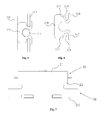
- the LED lamp with guide rail comprises a power supply rail 1, a power supply unit 2 and a lamp body3.
- the lamp body 3 comprises a reflective bracket 31, a LED light bar 32 and a lampshade 33.
- An overall structure of the power supply rail 1 is a groove-shaped structure.
- the interior of the power supply rail 1 forms a groove 34.
- the power supply unit 2 is movably arranged in the power supply rail 1.
- An overall structure of a section of the power supply unit 2 is a I-shaped structure.
- the power supply unit 2 comprises an upper part 35 and a lower part 36.
- the upper part 35 of the power supply unit 2 is located within the groove 34 and the lower part 36 of the power supply unit 2 is located outside the groove 34 of the power supply rail 1.
- a wrapping part 37 is arranged at edge of the backside of the reflective bracket 31.
- the wrapping part 37 is fixed on the lower part 36 of the power supply unit 2 through a bolt 38.
- the LED light bar 32 is connected onto the reflective bracket 31.
- the lampshade 33 is connected to the front side of the reflective bracket 31 and covers the LED light bar 32.
- the power supply unit 2 transmits power to the LED light bar 32 after taking power from the power supply rail 1.
- the lamp body 3 of the present invention is fixed on the power supply unit 2 by the wrapping part 37 of the backside of the reflective bracket 31 while the power supply unit 2 is mounted in the power supply rail 1. Because the wrapping part 37 is fixed on the power supply unit 2 through the bolt 38 and the bolt 38 can be easily tightened and unscrewed, it's easier to perform installation operations on the lamp body 3 and thus improve the installer's working efficiency.
- the power supply rail 1 and power supply unit 2 of the invention can be manufactured in accordance with a standard specification.
- the lamp body 3 with different sizes can be fitted through the power supply rail 1 by only producing different specifications of the corresponding reflector brackets 31 and lampshades 33, which thus can meet the different needs of different people.
- the lamp body 3 of the present invention is power-supplied from the power supply rail 1. Because the power supply rail 1 is usually made of metal profile and such metal profile is normally stretch-formed through a mold at the time of production, the straight effect can be achieved in a certain scope of length. Thus, at the time of installation, the technical effect of the linear straight can be achieved after the installation of the lamp.
- the lamp body 3 can easily be moved along the power supply rail 1 because it can obtain power from the entire power supply rail 1 without needs for change of the position of the rail 1, which is more convenient for the installer. Furthermore, the light emitted by the LED light bar 32, which is fully radiated and concentrated by the reflective bracket 31 and then comes out through the lampshade 33, makes the lighting of the entire lamp even and soft. Moreover, the reflective bracket 31 can be made of full aluminum and the reflective bracket 31 made of full aluminum material can provide a better heat dissipation area for LED light bar, which makes the power of LED lamp higher.
- the power supply rail 1 of the present invention comprises a top plate 39, two outer plates 310 and two inner plates 311.
- the top of the outer plate 310 and the inner plate 311 are fixed onto the top plate 39.
- the bottom of inner plate 311 and the outer plate 310 are provided with a support plate 312.
- the top plate 39, the outer plate 310, the inner plate 311 and the support plate 312 surround together to form a semi-closed groove 34.
- the groove 34 is used to hold the upper part 35 of the power supply unit 2. Because the upper part 35 of the power supply unit 2 is located within the groove 34, the power supply unit 2 can be supported by the support plate 312 without falling from the groove 34. Meanwhile, the power supply unit 2 is allowed to easily move along the power supply rail 1 in the longitudinal direction thereof.
- the inner plate 311 is provided with a first slot 313.
- This first slot 313 is provided with an insulating slot strip 314 thereon.
- the opening of the insulating slot strip 314 faces toward the groove 34.
- the insulating slot strip 314 is provided with a conductive wire 315 therein. It's very dangerous and unsafe for supplying power directly through the body of the power supply rail 1 due to the body of the entire power supply rail 1 is usually made of metal profiles.
- the conductive wire 315 is disposed in the insulating slot strip 314, the body of the power supply rail 1, i.e., the top plate 39, outer plate 310, inner plate 311 and the support plate 312 are electrically neutral and there will be no risk of leakage and electric shock.
- the insulating slot strip 314 is a rubber slot strip usually with certain flexibility and therefore the rubber slot strip can be stuck in the first slot 313 more convenient and more stable. Meanwhile, because the rubber slot has a large coefficient of friction, it can grip the conductive wire 315 very tightly and prevent the conductive wire 315 from falling out of the rubber slot.
- the cross-section of the insulating slot strip 314 is a " ⁇ " shaped structure.
- the insulating slot strip 314 comprises a base 316, two first connecting portions 317 and two second connecting portions 318. One end of two first connecting portions 317 are connected to two ends of the base 316. The other end of the first connecting portion 317 is connected to the second connecting portion 318.
- a bayonet 319 is formed after connection of the first connecting portion 317 and the second connecting portion 318. This bayonet 319 is clamped on the inner plate 311 of both sides of the first slot 313.
- the first connecting portion 317 covers a side of the inner plate 311 and the second connecting portion 318 covers the other side of the inner plate 311.
- the conductive wire 315 may be located inside the ⁇ -shaped structure so that the conductive wire 315 can be fixed to the insulating rubber strip tightly. Meanwhile, a larger insulating region can be created through covering the both sides of the inner plate 311 by the first connecting portion 317 and the second connecting portion 318 and the conductive wire 315 certainly cannot contact the inner plate 311. This can effectively prevent the possibility of leakage and electric shock.
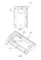
- the power supply unit 2 of the present invention comprises a top cap 21, a housing 22 and a bottom cap 23.
- the interior of the housing 22 is provided with a space for accommodating a driving power supply (not shown).
- the top cap 21 is covered on the housing 22 and the bottom cap 23 is arranged at the bottom of the housing 22.
- An outside wall of the housing 22 is provided with a fixed groove 24 and the fixed groove 24 cooperates with the support plate 312 to enable the power supply unit 2 to be fixed onto the power supply rail 1.
- the top cap 21, housing 22 and bottom cap 23 can all be made of insulating materials which can ensure the housing 22 of the power supply unit 2 is isolated from the conductive wire 315.
- the entire power supply unit 2 is mounted onto the power supply rail 1 with the cooperation of the fixed groove 24 and the support plate 312 and thus cannot fall down.
- the housing 22 of the present invention comprises a first portion 25 and a second portion 26.
- the fixed groove 24 is formed in the junction between the first portion 25 and the second portion 26.
- the width of the second portion 26 is greater than that of the first portion 25.
- a side of the second portion 26 is provided with a fixed hole 27 to be matched with the bolt 38. It is very easy to make installation by fixing the wrapping part 37 with the fixed hole 27 via the bolt 38 and thus these parts can be installed and removed easily because the second portion 26 of the housing 22 is located outside of the groove 34.
- the first portion 25 is provided with a first notch 28 on its two sides corresponding to a side wall of the power supply rail 1.
- the first notch 28 is provided with a first conductive sheet 29 with one end of the first conductive sheet 29 being connected to the conductive wire 315 and the other end of the first conductive sheet 29 being connected to the driving power supply.
- the first conductive sheet 29 is sticking out from the first notch 28 and thus it ensures that only the first conductive sheet 29 can be in contact with the conductive wire 315 and no leakage problems will be caused. Power from the conductive wire 315 can be supplied to the driving power supply by the connection of the first conductive sheet 29.
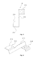
- the first conductive sheet 29 is of a "Z" shaped structure.
- This first conductive sheet comprises a mounting portion 210, an elastic portion 211 and a contact portion 212.
- the mounting portion 210 is used to mount the conductive sheet on the housing 22.
- the elastic portion 211 is connected onto the mounting portion 210.
- the contact portion 212 is in contact with the conductive wire 315.
- the contact portion 212 is connected onto the elastic portion 211.
- the housing 22 is provided with a retaining wall 213 cooperated with the elastic portion 211.
- One side of the retaining wall 213 which is facing to the elastic portion 211 is a slope.
- the distance between one end of the elastic portion 211 nearing the mounting portion 210 and the retaining wall 213 is less than the distance between one end of the elastic portion 210 nearing the contact portion 212 and the retaining wall 213.
- One end of the contact portion 212 which is in contact with conductive wire 315 is provided with an arcuate edge 214.
- the first conductive sheet 29 has an elastic portion 211
- the first conductive sheets 29 on both sides can be pressed in the direction towards the retaining wall 213 so that the elastic portion 211 is deformed.
- the contact portion 212 can be inwardly recessed at the first notched 28.
- the width of the entire power supply unit 2 becomes slightly narrower so that the first conductive sheet 29 could be just located between the two conductive wires 315.
- the elastic portion 211 has elastic force, the contact portion 212 can be in contact with the conductive wire 315 closer, which ensures the conductivity effect.
- one end by which the contact portion 212 is in contact with conductive wire 315 is provided with an arcuate edge 214, which can facilitate the power supply unit 2 moving on the power supply rail 1 without suffering from blocks and therefore facilitates adjustment of the installation location of the lamp body 3 on the entire LED lamp with guide rail.
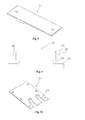
- the bottom of the driving power supply is connected with a second conductive sheet 215.
- the bottom cap 23 is provided with a second notch 216.
- One end on which the second conductive sheet 215 is away from the drive power supply cooperates with the second notch 216.
- a position of the second conductive sheet 215 nearing the second notch 216 is arcuate fold 217.
- One end portion of the second conductive sheet 215 nearing the second notch 216 is provided with a conductive contact 21.
- the elasticity of the second conductive sheet 215 can be increased after arranging this arcuate fold 217 so that the conductive contact 218 has a greater downward pressure.
- the second conductive sheet 215 can transmit the current converted through the driving power supply to the LED light bar 32.
- the reflective bracket 31 further comprises a radiating back plate 320, two side plates 321 and an arcuate reflective plate 322.
- the two side plates 321, the radiating back plate 320 and the arcuate reflective plate 322 surround together to form a hollow space.
- the radiating back plate 320 and the wrapping part 37 is an integrated structure.
- An inside face of the arcuate reflective plate 322 is provided with a second slot 323.
- the LED light bar 32 is stuck in the second slot 322.
- Two sides of the arcuate reflective plate 322 is provided with a third slot 324, as shown in Fig. 19 , two sides of the lampshade 33 is provided with a card edge 325 and the card edge 325 is stuck in the third slot 324.
- the hollow space formed with the reflective bracket 31 is used to save material, which makes the reflective bracket 31 lighter and easier to install.
- the wrapping part 37 with the entire reflective bracket 31 can further increase the area of the entire reflective bracket, thereby increases the radiating area and improve the radiating effect.
- Each lamp body 3 can be equipped with two power supply units 2 and the two power supply units 2 are located at both ends of the lamp body 3 respectively so that the lamp body 3 can be interposed between the two power supply units 2.
- the LED lamp with guide rail further comprises an end cap 326.
- This end cap 326 comprises a body 327 and a support plate 328.
- the support plate 328 is fixed to one side of the body 327.
- the support plate 328 is provided with a stopper 329 thereon.
- the stopper 329 is corresponding to the second conductive sheet 215.
- the support plate 328 is further provided with a through hole 330 thereon.
- the lamp body 3 can have a more confined space through use of the end cap 326, which can prevent dusts from falling into the lampshade 33 and ensure a good lighting effect.
- the power supply unit 2 can be well supported through the support plate 328 to maintain the stability of the power supply unit 2.
- cooperation of the stopper 329 with the second conductive sheet 215 can ensure the second conductive sheet 215 does not have displacement.
- the through hole 330 on the support plate 328 can be used for passing through the conductive wire in order to facilitate the connection of the second conductive sheet 215 and LED light bar 32.
Landscapes
- Engineering & Computer Science (AREA)
- General Engineering & Computer Science (AREA)
- Power Engineering (AREA)
- Non-Portable Lighting Devices Or Systems Thereof (AREA)
- Arrangement Of Elements, Cooling, Sealing, Or The Like Of Lighting Devices (AREA)
Applications Claiming Priority (1)
| Application Number | Priority Date | Filing Date | Title |
|---|---|---|---|
| PCT/CN2015/072526 WO2016127288A1 (zh) | 2015-02-09 | 2015-02-09 | 导轨式led灯具 |
Publications (1)
| Publication Number | Publication Date |
|---|---|
| EP3056808A1 true EP3056808A1 (de) | 2016-08-17 |
Family
ID=53365781
Family Applications (1)
| Application Number | Title | Priority Date | Filing Date |
|---|---|---|---|
| EP15169573.1A Withdrawn EP3056808A1 (de) | 2015-02-09 | 2015-05-28 | Led-lampe mit führungsschiene |
Country Status (3)
| Country | Link |
|---|---|
| EP (1) | EP3056808A1 (de) |
| CN (1) | CN105491704B (de) |
| WO (2) | WO2016127288A1 (de) |
Cited By (8)
| Publication number | Priority date | Publication date | Assignee | Title |
|---|---|---|---|---|
| CN107877145A (zh) * | 2017-05-25 | 2018-04-06 | 广州迅速光电科技有限公司 | 一种新型led灯板组装设备 |
| IT201700078025A1 (it) * | 2017-07-11 | 2019-01-11 | C&G S A S Di Ruggero Grandi & C | Sistema per la partizione di un ambiente |
| EP3428360A1 (de) * | 2017-07-11 | 2019-01-16 | C&G S.a.s. | Multifunktionales, abhängbares deckensystem zur teilung und beleuchtung eines raumes |
| CN112923280A (zh) * | 2021-02-23 | 2021-06-08 | 上海光联照明有限公司 | 一种紧固直接扣入式的灯具固定装置和灯具安装方法 |
| EP3798504A4 (de) * | 2018-07-25 | 2021-06-30 | Suzhou Opple Lighting Co., Ltd. | Schienenleuchte |
| CN114173445A (zh) * | 2021-11-29 | 2022-03-11 | 四维生态科技(杭州)有限公司 | 一种基于电压调制的光谱调节系统及方法 |
| AT17489U1 (de) * | 2019-02-06 | 2022-06-15 | Zumtobel Lighting Gmbh At | Lichtbandsystem mit länglicher Trägeranordnung und mehreren Leuchteneinheiten |
| USD957025S1 (en) * | 2019-11-08 | 2022-07-05 | Lin Qiu | LED light |
Families Citing this family (4)
| Publication number | Priority date | Publication date | Assignee | Title |
|---|---|---|---|---|
| CN107270165B (zh) * | 2017-06-26 | 2019-08-30 | 江苏鸿佳电子科技有限公司 | 一种抗震加强的散热节能led灯条 |
| CN108626632B (zh) * | 2018-03-28 | 2025-02-21 | 深圳市倍盛鸿照明有限公司 | 一种橱柜灯具 |
| CN108826117A (zh) * | 2018-07-30 | 2018-11-16 | 深圳市深川科技有限公司 | 一种安装于智能家具中的发光源控制系统 |
| CN110185975B (zh) * | 2019-06-28 | 2024-03-19 | 商洛市虎之翼科技有限公司 | 导轨照明灯具及具有该导轨照明灯具的照明系统 |
Citations (3)
| Publication number | Priority date | Publication date | Assignee | Title |
|---|---|---|---|---|
| EP2436974A1 (de) * | 2008-11-05 | 2012-04-04 | Zumtobel Lighting GmbH | LED-Leuchte |
| EP2672177A1 (de) * | 2012-06-07 | 2013-12-11 | Koninklijke Philips N.V. | LED-Beleuchtungsvorrichtung und LED-Beleuchtungsanordnung |
| CN104235686A (zh) * | 2014-08-19 | 2014-12-24 | 苏州市琳珂照明科技有限公司 | Led灯具 |
Family Cites Families (10)
| Publication number | Priority date | Publication date | Assignee | Title |
|---|---|---|---|---|
| SE0950298A1 (sv) * | 2009-05-04 | 2010-11-05 | Vadsbo Innovation Ab | Arrangemang av elektrisk krets |
| CN201439885U (zh) * | 2009-06-23 | 2010-04-21 | 深圳市桑达实业股份有限公司 | 一种大功率led照明系统 |
| CN101701698A (zh) * | 2009-10-24 | 2010-05-05 | 王永发 | 一种可弯曲的led灯导轨 |
| CN201715311U (zh) * | 2010-06-13 | 2011-01-19 | 钱江涛 | 内置高功率因数的led日光灯 |
| US8330362B2 (en) * | 2010-07-22 | 2012-12-11 | Chiu-Min Lin | Lamp having mounting slot |
| CN202938121U (zh) * | 2012-12-06 | 2013-05-15 | 鲁周波 | Led灯具 |
| CN203202806U (zh) * | 2013-03-22 | 2013-09-18 | 鲁周波 | 一种led直管灯具 |
| CN104125674A (zh) * | 2013-04-26 | 2014-10-29 | 国钰电子(北海)有限公司 | 发光二极管驱动系统 |
| CN103398351B (zh) * | 2013-08-05 | 2015-08-05 | 广州市莱帝亚照明科技有限公司 | 一种led悬吊灯 |
| CN204114713U (zh) * | 2014-08-19 | 2015-01-21 | 苏州市琳珂照明科技有限公司 | Led灯具 |
-
2015
- 2015-02-09 WO PCT/CN2015/072526 patent/WO2016127288A1/zh not_active Ceased
- 2015-05-28 EP EP15169573.1A patent/EP3056808A1/de not_active Withdrawn
- 2015-11-12 CN CN201510770475.3A patent/CN105491704B/zh not_active Expired - Fee Related
- 2015-11-13 WO PCT/CN2015/094501 patent/WO2016127679A1/zh not_active Ceased
Patent Citations (3)
| Publication number | Priority date | Publication date | Assignee | Title |
|---|---|---|---|---|
| EP2436974A1 (de) * | 2008-11-05 | 2012-04-04 | Zumtobel Lighting GmbH | LED-Leuchte |
| EP2672177A1 (de) * | 2012-06-07 | 2013-12-11 | Koninklijke Philips N.V. | LED-Beleuchtungsvorrichtung und LED-Beleuchtungsanordnung |
| CN104235686A (zh) * | 2014-08-19 | 2014-12-24 | 苏州市琳珂照明科技有限公司 | Led灯具 |
Cited By (10)
| Publication number | Priority date | Publication date | Assignee | Title |
|---|---|---|---|---|
| CN107877145A (zh) * | 2017-05-25 | 2018-04-06 | 广州迅速光电科技有限公司 | 一种新型led灯板组装设备 |
| IT201700078025A1 (it) * | 2017-07-11 | 2019-01-11 | C&G S A S Di Ruggero Grandi & C | Sistema per la partizione di un ambiente |
| EP3428360A1 (de) * | 2017-07-11 | 2019-01-16 | C&G S.a.s. | Multifunktionales, abhängbares deckensystem zur teilung und beleuchtung eines raumes |
| EP3798504A4 (de) * | 2018-07-25 | 2021-06-30 | Suzhou Opple Lighting Co., Ltd. | Schienenleuchte |
| AT17489U1 (de) * | 2019-02-06 | 2022-06-15 | Zumtobel Lighting Gmbh At | Lichtbandsystem mit länglicher Trägeranordnung und mehreren Leuchteneinheiten |
| USD957025S1 (en) * | 2019-11-08 | 2022-07-05 | Lin Qiu | LED light |
| CN112923280A (zh) * | 2021-02-23 | 2021-06-08 | 上海光联照明有限公司 | 一种紧固直接扣入式的灯具固定装置和灯具安装方法 |
| CN112923280B (zh) * | 2021-02-23 | 2022-07-08 | 上海光联照明有限公司 | 一种紧固直接扣入式的灯具固定装置和灯具安装方法 |
| CN114173445A (zh) * | 2021-11-29 | 2022-03-11 | 四维生态科技(杭州)有限公司 | 一种基于电压调制的光谱调节系统及方法 |
| CN114173445B (zh) * | 2021-11-29 | 2023-12-22 | 四维生态科技(杭州)有限公司 | 一种基于电压调制的光谱调节系统及方法 |
Also Published As
| Publication number | Publication date |
|---|---|
| WO2016127288A1 (zh) | 2016-08-18 |
| CN105491704B (zh) | 2017-11-17 |
| WO2016127679A1 (zh) | 2016-08-18 |
| CN105491704A (zh) | 2016-04-13 |
Similar Documents
| Publication | Publication Date | Title |
|---|---|---|
| EP3056808A1 (de) | Led-lampe mit führungsschiene | |
| CN104235686B (zh) | Led灯具 | |
| CN104633574B (zh) | 导轨式led灯具 | |
| CN103759196A (zh) | 嵌入式立体凹槽龙骨灯 | |
| CN105371148A (zh) | 一种i形led灯 | |
| CN204114713U (zh) | Led灯具 | |
| CN202484938U (zh) | 铝合金线槽led灯具结构 | |
| CN204328522U (zh) | 一种led灯 | |
| CN103775859A (zh) | Led三防灯及其导热散热方法 | |
| CN206530897U (zh) | 一种节能led灯管 | |
| US11441744B2 (en) | Elongated frame lamp | |
| CN215061873U (zh) | 一种接触式轨道照明灯 | |
| CN202972609U (zh) | 可拼接led平板灯具 | |
| CN210107115U (zh) | 一种多元化出光的照明灯具 | |
| CN203797424U (zh) | 一种整体式散热的超薄led筒灯 | |
| CN204164720U (zh) | 一种led日光灯 | |
| CN202501324U (zh) | Led直列型工矿灯 | |
| US20210140591A1 (en) | Elongated frame lamp | |
| CN209101057U (zh) | 一种接线组件内置的筒灯 | |
| CN206377536U (zh) | 一种具有多种发光面的模组化led台阶灯 | |
| CN207298494U (zh) | 一种磁铁安装led线条灯 | |
| CN212157048U (zh) | 一种用于灯具的铝型材结构 | |
| CN219453761U (zh) | 一种可双边安装光源的灯具型材 | |
| CN219493893U (zh) | 一种回形针式led落地灯 | |
| CN206522666U (zh) | 多面发光井道灯 |
Legal Events
| Date | Code | Title | Description |
|---|---|---|---|
| PUAI | Public reference made under article 153(3) epc to a published international application that has entered the european phase |
Free format text: ORIGINAL CODE: 0009012 |
|
| 17P | Request for examination filed |
Effective date: 20150623 |
|
| AK | Designated contracting states |
Kind code of ref document: A1 Designated state(s): AL AT BE BG CH CY CZ DE DK EE ES FI FR GB GR HR HU IE IS IT LI LT LU LV MC MK MT NL NO PL PT RO RS SE SI SK SM TR |
|
| AX | Request for extension of the european patent |
Extension state: BA ME |
|
| RBV | Designated contracting states (corrected) |
Designated state(s): AL AT BE BG CH CY CZ DE DK EE ES FI FR GB GR HR HU IE IS IT LI LT LU LV MC MK MT NL NO PL PT RO RS SE SI SK SM TR |
|
| GRAP | Despatch of communication of intention to grant a patent |
Free format text: ORIGINAL CODE: EPIDOSNIGR1 |
|
| RIC1 | Information provided on ipc code assigned before grant |
Ipc: F21V 7/00 20060101ALN20161219BHEP Ipc: F21S 4/28 20160101ALI20161219BHEP Ipc: F21V 17/12 20060101ALN20161219BHEP Ipc: F21V 23/02 20060101ALI20161219BHEP Ipc: F21Y 103/10 20160101ALN20161219BHEP Ipc: F21V 21/35 20060101AFI20161219BHEP Ipc: F21Y 115/10 20160101ALN20161219BHEP |
|
| INTG | Intention to grant announced |
Effective date: 20170120 |
|
| STAA | Information on the status of an ep patent application or granted ep patent |
Free format text: STATUS: THE APPLICATION IS DEEMED TO BE WITHDRAWN |
|
| 18D | Application deemed to be withdrawn |
Effective date: 20170531 |