EP3056818A2 - Neuartiges verfahren für einen lufteinlass in einer hülle zur reduzierung der anforderungen von wasser zur kontrolle von nox - Google Patents
Neuartiges verfahren für einen lufteinlass in einer hülle zur reduzierung der anforderungen von wasser zur kontrolle von nox Download PDFInfo
- Publication number
- EP3056818A2 EP3056818A2 EP16153116.5A EP16153116A EP3056818A2 EP 3056818 A2 EP3056818 A2 EP 3056818A2 EP 16153116 A EP16153116 A EP 16153116A EP 3056818 A2 EP3056818 A2 EP 3056818A2
- Authority
- EP
- European Patent Office
- Prior art keywords
- combustor
- air
- holes
- mixing
- wall
- Prior art date
- Legal status (The legal status is an assumption and is not a legal conclusion. Google has not performed a legal analysis and makes no representation as to the accuracy of the status listed.)
- Withdrawn
Links
- XLYOFNOQVPJJNP-UHFFFAOYSA-N water Substances O XLYOFNOQVPJJNP-UHFFFAOYSA-N 0.000 title description 11
- 238000000034 method Methods 0.000 title description 4
- 238000002156 mixing Methods 0.000 claims abstract description 95
- 238000010790 dilution Methods 0.000 claims abstract description 90
- 239000012895 dilution Substances 0.000 claims abstract description 90
- 238000002485 combustion reaction Methods 0.000 claims abstract description 83
- 239000000567 combustion gas Substances 0.000 claims abstract description 42
- 238000001816 cooling Methods 0.000 claims abstract description 39
- 238000010791 quenching Methods 0.000 claims abstract description 11
- 230000000171 quenching effect Effects 0.000 claims abstract description 10
- 239000000446 fuel Substances 0.000 claims description 58
- UGFAIRIUMAVXCW-UHFFFAOYSA-N Carbon monoxide Chemical compound [O+]#[C-] UGFAIRIUMAVXCW-UHFFFAOYSA-N 0.000 claims description 35
- 229910002091 carbon monoxide Inorganic materials 0.000 claims description 35
- 238000011144 upstream manufacturing Methods 0.000 claims description 26
- 239000007789 gas Substances 0.000 claims description 18
- 238000004519 manufacturing process Methods 0.000 claims description 16
- 239000000498 cooling water Substances 0.000 abstract description 3
- 229910002089 NOx Inorganic materials 0.000 description 29
- 238000009792 diffusion process Methods 0.000 description 15
- VNWKTOKETHGBQD-UHFFFAOYSA-N methane Chemical compound C VNWKTOKETHGBQD-UHFFFAOYSA-N 0.000 description 10
- 238000006243 chemical reaction Methods 0.000 description 7
- MWUXSHHQAYIFBG-UHFFFAOYSA-N Nitric oxide Chemical class O=[N] MWUXSHHQAYIFBG-UHFFFAOYSA-N 0.000 description 5
- 239000003345 natural gas Substances 0.000 description 5
- 230000035515 penetration Effects 0.000 description 5
- 230000015572 biosynthetic process Effects 0.000 description 4
- JCXJVPUVTGWSNB-UHFFFAOYSA-N Nitrogen dioxide Chemical compound O=[N]=O JCXJVPUVTGWSNB-UHFFFAOYSA-N 0.000 description 3
- 238000010793 Steam injection (oil industry) Methods 0.000 description 2
- 238000004891 communication Methods 0.000 description 2
- 239000003344 environmental pollutant Substances 0.000 description 2
- 231100000719 pollutant Toxicity 0.000 description 2
- 230000007704 transition Effects 0.000 description 2
- MGWGWNFMUOTEHG-UHFFFAOYSA-N 4-(3,5-dimethylphenyl)-1,3-thiazol-2-amine Chemical compound CC1=CC(C)=CC(C=2N=C(N)SC=2)=C1 MGWGWNFMUOTEHG-UHFFFAOYSA-N 0.000 description 1
- 230000003247 decreasing effect Effects 0.000 description 1
- 230000000694 effects Effects 0.000 description 1
- 230000005611 electricity Effects 0.000 description 1
- 239000000284 extract Substances 0.000 description 1
- 239000007788 liquid Substances 0.000 description 1
- 238000012986 modification Methods 0.000 description 1
- 230000004048 modification Effects 0.000 description 1
- 238000003786 synthesis reaction Methods 0.000 description 1
Images


Classifications
-
- F—MECHANICAL ENGINEERING; LIGHTING; HEATING; WEAPONS; BLASTING
- F23—COMBUSTION APPARATUS; COMBUSTION PROCESSES
- F23R—GENERATING COMBUSTION PRODUCTS OF HIGH PRESSURE OR HIGH VELOCITY, e.g. GAS-TURBINE COMBUSTION CHAMBERS
- F23R3/00—Continuous combustion chambers using liquid or gaseous fuel
- F23R3/02—Continuous combustion chambers using liquid or gaseous fuel characterised by the air-flow or gas-flow configuration
- F23R3/04—Air inlet arrangements
- F23R3/06—Arrangement of apertures along the flame tube
-
- F—MECHANICAL ENGINEERING; LIGHTING; HEATING; WEAPONS; BLASTING
- F23—COMBUSTION APPARATUS; COMBUSTION PROCESSES
- F23R—GENERATING COMBUSTION PRODUCTS OF HIGH PRESSURE OR HIGH VELOCITY, e.g. GAS-TURBINE COMBUSTION CHAMBERS
- F23R3/00—Continuous combustion chambers using liquid or gaseous fuel
- F23R3/02—Continuous combustion chambers using liquid or gaseous fuel characterised by the air-flow or gas-flow configuration
- F23R3/04—Air inlet arrangements
- F23R3/045—Air inlet arrangements using pipes
Definitions
- the present invention relates turbines, and more particularly to a method of introducing air into a gas turbine combustor to reduce combustor NOx emissions and water requirements in reducing such emissions.
- Gas turbine engines include a compressor for compressing air that is mixed with fuel and ignited in a combustor for generating combustion gases.
- the combustion gases from the combustor flow to a turbine that extracts energy for driving a shaft to power the compressor and produces output power, often for powering an electrical generator.
- NOx mono-nitrogen oxides NO (nitric oxide) and NO2 (nitrogen dioxide)
- CO carbon monoxide
- Conventional turbine combustors use non-premixed diffusion flames, where fuel and air freely enter the combustion chamber separately and mixing of the fuel and air occurs simultaneously with combustion, and where resulting flame temperatures typically exceed 4000° F with NG, LF or syngas fuels, so as to produce relatively high levels of NOx emissions.
- temperatures in combustion chamber primary zones can get very high if water is not injected, although temperatures do drop along the length of the combustion chamber.
- Water is generally used because a diffusion flame is used in these combustors and primary zone temperatures are very high and produce NOx as much as approximately 250 ppm with syngas/LF fuels and approximately 120 ppm with NG fuel if water is not used.
- the present invention seeks to reduce water requirements in conventional combustors to reduce temperatures and NOx emissions when operating on NG/LF or syngas fuels.
- combustion in a conventional combustor is changed from “rich to lean” to "rich to quench to lean” by changing the air entry arrangement in the liner of the conventional combustor.
- dilution holes are removed, liner cooling is reduced and dilution air is admitted into the combustor liner in place of mixing air admitted into the combustor liner through a third row of mixing holes.
- dilution air is admitted into the combustor liner with the help of a plurality of pipes arranged in such a manner so that such air comes into the liner as a swirling flow in a direction opposite to nozzle swirl, so as to thereby produce a large mixing of air with the combustion gases and a resulting quenching effect, i.e., a rapid cooling of the combustion gases by quenching air.
- a rapid cooling of the combustion gases by quenching air i.e., a rapid cooling of the combustion gases by quenching air.
- the present invention reduces temperatures in the primary reaction zone of a combustor by moving dilution air upstream and providing swirl to incoming air to enhance mixing. Reduction in temperature leads to reduction in NOx generation which is very high in conventional liners before combustion gases reach the dilution holes in the combustor.
- the present invention also reduces the cooling water requirement in conventional liners, which is typically very high.
- a combustor operating with a compressor to drive a gas turbine is comprised of an outer combustor wall having an upstream fuel entry end and a downstream turbine entry end; a plurality of mixing holes located proximal to the upstream fuel entry end of the outer combustor wall; and a plurality of dilution holes located proximal to the plurality of mixing holes to admit air into a combustion zone in the combustor for mixing of the admitted air with combustion gases in the combustion zone to thereby reduce NOx and carbon monoxide (CO) production in the combustion zone.
- CO carbon monoxide
- a combustor operating with a compressor to drive a gas turbine is comprised of an outer combustor wall having an upstream fuel entry end and a downstream turbine entry end; a plurality of mixing holes located proximal to the upstream fuel entry end of the outer combustor wall, the plurality of mixing holes being arranged in a plurality of rows which extend around a circumference of the outer combustor wall; and a plurality of dilution holes arranged in one or more rows which extend around the circumference of the outer combustor wall, the plurality of dilution holes being located proximal to the plurality of mixing holes; an outer shell; a nozzle from which compressed air and fuel are discharged into combustor; a flow sleeve located between the outer shell and the combustor wall so as to form a cavity between the outer shell and the combustor wall so that air from the compressor entering the combustor is divided between a first path by which a first part of the
- a combustor operating with a compressor to drive a gas turbine is comprised of an outer combustor wall having an upstream fuel entry end and a downstream turbine entry end, the outer combustor wall having a length between 35 inches and 50 inches; a plurality of rows of liner louver cooling holes positioned longitudinally along the combustor wall; a plurality of mixing holes located proximal to the upstream fuel entry end of the outer combustor wall; the plurality of dilution holes being located proximal to the plurality of mixing holes; the plurality of mixing holes being arranged in first and second rows which extend around a circumference of the outer combustor wall rather than first, second and third rows which extend around the circumference of the outer combustor wall so that the plurality of dilution holes are arranged in the third row from the upstream fuel entry end extending around the circumference of the outer combustor wall so as to be located within a distance of five inches to forty inches from the fuel
- FIG. 1 of U.S. Patent No. 6,192,689 is a schematic representation of a portion of an exemplary industrial gas turbine engine 10 having a low NOx combustor 18 joined in flow communication with a compressor 12 and turbine 20.
- the industrial gas turbine engine 10 includes a compressor 12 for compressing air 14 that is mixed with fuel 16 and ignited in at least one combustor 18, as shown in FIG. 1 .
- a turbine 20 is coupled to compressor 12 by a drive shaft 22, a portion of which drive shaft 22 extends for powering, for example, an electrical generator (not shown) for generating electrical power.
- compressor 12 discharges compressed air 14 that is mixed with fuel 16 and ignited for generating combustion gases 24 from which energy is extracted by turbine 20 for rotating shaft 22 to power compressor 12, as well as for producing output power for driving the generator or other external load.
- Combustor 18 comprises a cylindrical combustor wall 26, which defines a combustion chamber 28 cylindrical combustor wall 26.
- FIGS. 2A and 2B are side elevational and perspective schematic representations, respectively, of a conventional combustor liner 30 used in an industrial gas turbine engine 10.
- the combustor 30 includes a cylindrical combustor wall 32 having a fuel entry end 34 and a turbine entry end 36.
- the combustor liner 30 includes a plurality of rows of liner louvers cooling holes 38 positioned longitudinally along the liner 30 and having different diameters at different positions along the liner 30.
- the combustor liner 30 is also comprised of several sets of air holes disposed about its periphery.
- a first set of air holes 40 referred to as mixing holes, supply a quantity of air to the reaction zone within combustion chamber 28.
- the mixing holes 40 are disposed proximate to the fuel entry end 34 of combustor 30 to provide an entry for mixing air.
- the number of mixing holes 40 is variable, typically depending on the overall size of combustor 30.
- a second set of air holes 42 are positioned at the downstream end of the combustion chamber to quench combustion gases 24 prior to entering a transition piece (not shown) or a turbine inlet (not shown).
- a second set of air holes 42 are disposed in a central region of the combustor 30, closer to the downstream end of the combustion chamber 28 within combustor 30.
- the dilution holes 42 provide an entry area for dilution air into to combustor 30.
- the dilution air is provided to lower the temperature of combustion gases 24 prior to entering a turbine inlet (not shown) or a transition piece (not shown).
- the temperature field within combustor 30 during operation is such that temperatures are very high in the primary zone of combustor 30, if water is not injected into combustor 30, although it should be noted that temperatures drop along the length of combustor 30.
- NOx formation rates are highest in a narrow zone, with not much of the NOx being formed after the dilution holes 42 in combustor 30. Thus, the dilution holes' air does not participate in temperature and NOx reduction in conventional combustor 30.
- combustion in a conventional combustor is changed from “rich” to “lean” to “rich” to “quench” to “lean” by changing the air entry arrangement of the conventional combustor.
- the air entry arrangement according to the present invention dilution holes are removed from the region of the combustor closer to the downstream end of the combustion chamber within combustor, liner cooling is reduced and air is admitted into the combustor at the third row of the mixing holes with the help of a plurality pipes arranged in a manner that causes air coming from the pipes to enter the combustor 30 as swirling flow in a direction opposite to nozzle swirl, so as to therefore produce a large mixing and quenching effect.
- the plurality of pipes comprises six pipes.
- FIG. 3 is a perspective schematic representation of a combustor liner 50 according to the present invention.
- the combustor 50 includes a cylindrical combustor wall 52 having a fuel entry end 54 and a turbine entry end 56. In the combustor 50, the air entry arrangement has been changed so that dilution air is admitted into the combustor 50 closer to a fuel entry end 54.
- the combustor wall 52 also has a plurality of rows of liner louver cooling holes 58 positioned longitudinally along the combustor 50 and having different diameters at different positions along the combustor 50.
- the combustor 50 includes several sets of air holes disposed about its periphery.
- the combustor 50 includes a set of mixing holes 60 which are disposed proximate to the fuel entry end 54 of combustor 50 to provide an entry for a quantity of mixing air to be supplied to the reaction zone within the combustion chamber 28.
- the combustor 50 also includes a set of dilution holes 62. Again, the number of mixing holes 60 and the number of dilution holes 62 vary according to the overall size of combustor 50.
- a preferred embodiment of the combustor wall 52 has a preferred nominal diameter (d) in the range between about 9 inches to about 15 inches and a preferred nominal length (L) in the range between about 35 inches to about 50 inches.
- the mixing holes 60 have a preferred diameter in the range between about 0.5 inches to about 1 inch
- the dilution holes 62 have a preferred diameter in the range between about 1.25 inches to about 4.0 inches.
- FIGS. 4A to 4C show a first embodiment of a Dry Low NOx (“DLN") combustion system incorporating the combustor liner 50 shown in FIG. 3 .
- the DLN combustion system includes combustor liner 50, a nozzle 51 from which compressed air 14 and fuel 16 that is mixed with the compressed air 14 is discharged into combustor 50 and a diverging cone 53 positioned between nozzle 51 and combustor 50.
- An endplate 55 holds the body of the combustor 50 together.
- the mixing holes 60 are preferably arranged in two rows, which extend around the circumference of the cylindrical combustor wall 52, and which are proximate to the fuel entry end 54 of the cylindrical combustor wall 52.
- the dilution holes 52 are arranged in a single row, which replaces a third row of mixing holes that would typically be present in a conventional combustor.
- the row of dilution holes 52 preferably extends around the circumference of the cylindrical combustor wall 52, and is proximate to the two rows of mixing holes 60 in cylindrical combustor wall 52 so that dilution air is admitted into the combustor 50 proximate to the fuel entry end 54 of combustor 50.
- the dilution holes 62 are located within a range of 5 inches to 40 inches from the fuel entry end 54 of the combustor wall 52.
- part of the mixing holes 60 i.e., those typically located in the third row of mixing holes are removed, and the number of dilution holes 62 is increased.
- eight of the 24 mixing holes 60 in a conventional combustor i.e., those holes in the third row of mixing holes, are removed, and the number of dilution holes 62 is increased from four typically in a conventional combustor to six to maintain jet penetration for mixing air to be supplied to the reaction zone within the combustion chamber 28.
- Mid- frame air 64 from the compressor 12 continues to be admitted into the combustor 50 by entering through flow sleeve 66 within a shell 74 containing combustor 50.
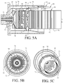
- FIG. 5A to 5C show a second embodiment of a DLN combustion system incorporating the combustor 50 shown in FIG. 3 .
- the modified liner shown in the embodiment of FIGs. 4A to 4C is maintained.
- the embodiment shown in FIG. 5A to 5C also includes a modified cavity arrangement for much larger mixing of air with the combustion gases within the combustion chamber 28.
- the dilution holes 52 are again moved to the third row of mixing holes 50 in combustor wall 62 so that dilution air is admitted into the combustor 50 at the third row of mixing holes 50, and, as such, the mixing holes 50 in the third row are removed.
- the mid- frame air 64 is divided into two paths, i.e., one path for a part of the mid-frame air 64 to continue to be admitted into the combustor 50 by entering through flow sleeve 66, and another path for another part 68 of the mid-frame air 64 to flow through a cavity 70 between the flow sleeve 66 and the outer shell 74, whereupon air flowing through the cavity 70 will tangentially enter the combustor 50 through a plurality of pipes 72 extending at an angle between the cavity 70 and the third row dilution holes 62 into the combustor 50.
- the air 68 entering the combustor 50 tangentially through pipes 72 results in an increase in air mixing with combustion gases 24 in the combustor primary zone.
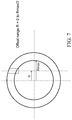
- the angle at which the pipes 72 enter the combustor 50 in a preferred embodiment is achieved using a range of offsets of zero to seven inches of the pipes from the center of the combustor 50, as shown in FIG. 7 .
- the mixing is improved because air flowing from the pipes 72 flows counterclockwise to the air flowing from the nozzle 51.
- FIG. 6A to 6C show a third embodiment of a DLN combustion system incorporating the combustor 50 shown in FIG. 5 .
- the modified liner with relocated dilution holes as shown in the embodiment of FIGs. 4A to 4C , is again used.
- the modified cavity arrangement for much larger mixing of air and combustion gases in the embodiment shown in FIG. 5A to 5C is again used.
- increased air flow of 10 - 15% is added to increase the penetration of air into the hot temperature zones in the combustion chamber 28. This is achieved by increasing the size/diameter of the dilution holes 62 though which air from pipes 72 is passed into combustor 50.
- louver cooling air passing through the plurality of rows of louver cooling holes 58 in the combustor liner 50 is reduced by half from 25-35% of the mid-frame air flow 64 to 10-15% of the mid-frame air flow 64 by decreasing the size/diameter of the cooling holes 58. It is noted that 25-35% louver cooling is an old design, in which the liner temperature can reach to 800°F to 1000°F in temperature.
- FIG. 8 is a partial breakaway perspective view of part of a diffusion type combustor 80.
- the combustor includes an inlet nozzle 81, a combustor liner 82 with a cylindrical combustor wall, and a flow sleeve 84 through which mid-frame air enters the combustor 80.
- Fig.9A is a picture of a temperature field within the diffusion type combustor 80 of Fig. 8 during operation with the liner 82 being a conventional type liner like that shown in FIGs. 2A and 2B .
- Fig. 9B is a picture of a temperature field within the diffusion type combustor 80 of Fig. 8 during operation with the liner 82 being of a type like that shown in FIG. 3 .
- FIG. 9B where a type of liner like that shown in FIG. 3 is used, the temperatures in the combustor 80 are less than those shown in FIG. 9A where a conventional type liner like that shown in FIGs. 2A and 2B is used. It can be seen from FIGS.
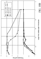
- Fig. 10A is a graph of the emissions inside and that exit a diffusion type combustor 80 like that of Fig. 8 during operation with a conventional type liner like that shown in FIGs. 2A and 2B and with a type liner according to the present invention like that shown in FIG. 3 .
- Fig. 10B is a graph of the temperature inside and that exit a diffusion type combustor like that of Fig. 8 during operation with a conventional type liner like that shown in FIGs. 2A and 2B and with a type liner according to the present invention like that shown in FIG. 3 .
- FIGS. 9A and 9B and the graph of FIG. 10B that the high temperature reaction zone within the combustion chamber 28 is reduced significantly after the dilution holes 62 have been moved closer to the fuel entry end 54 of the cylindrical combustor wall 52, so that the diffusion type combustor 80 of Fig. 8 was operated a liner 82 of a type like that shown in FIG. 3 , even though the exit profile of the combustor did not change much. It can also be seen from the graph of FIG. 10A that the combustor 80 of Fig. 8 , when operated with a liner 82 of a type like that shown in FIG. 3 , reduces NOx emissions by approximately 65% and CO emissions by approximately 50% at the exit of combustor 80.
Landscapes
- Engineering & Computer Science (AREA)
- Chemical & Material Sciences (AREA)
- Combustion & Propulsion (AREA)
- Mechanical Engineering (AREA)
- General Engineering & Computer Science (AREA)
Applications Claiming Priority (1)
| Application Number | Priority Date | Filing Date | Title |
|---|---|---|---|
| US14/608,342 US9453646B2 (en) | 2015-01-29 | 2015-01-29 | Method for air entry in liner to reduce water requirement to control NOx |
Publications (2)
| Publication Number | Publication Date |
|---|---|
| EP3056818A2 true EP3056818A2 (de) | 2016-08-17 |
| EP3056818A3 EP3056818A3 (de) | 2017-03-01 |
Family
ID=55701672
Family Applications (1)
| Application Number | Title | Priority Date | Filing Date |
|---|---|---|---|
| EP16153116.5A Withdrawn EP3056818A3 (de) | 2015-01-29 | 2016-01-28 | Neuartiges verfahren für einen lufteinlass in einer hülle zur reduzierung der anforderungen von wasser zur kontrolle von nox |
Country Status (4)
| Country | Link |
|---|---|
| US (1) | US9453646B2 (de) |
| EP (1) | EP3056818A3 (de) |
| JP (1) | JP2016169936A (de) |
| CN (1) | CN105889980A (de) |
Cited By (1)
| Publication number | Priority date | Publication date | Assignee | Title |
|---|---|---|---|---|
| FR3084448A1 (fr) * | 2018-07-30 | 2020-01-31 | IFP Energies Nouvelles | Chambre de combustion pour une turbine a gaz destinee a la production d'energie notamment d'energie electrique, comprenant des trous de dilution orientes dans un tube a flamme. |
Families Citing this family (5)
| Publication number | Priority date | Publication date | Assignee | Title |
|---|---|---|---|---|
| US20220316703A1 (en) * | 2019-06-12 | 2022-10-06 | Jerry Don Thompson | Burner flare tip |
| EP4202301B1 (de) * | 2021-12-21 | 2026-03-11 | General Electric Company | Brennkammer mit verdünnungsöffnungen |
| US11774100B2 (en) * | 2022-01-14 | 2023-10-03 | General Electric Company | Combustor fuel nozzle assembly |
| EP4390226A1 (de) * | 2022-12-20 | 2024-06-26 | General Electric Company | Gasturbinenbrennkammer mit einem satz von verdünnungspassagen |
| CN116464990B (zh) * | 2023-04-12 | 2025-05-09 | 西安热工研究院有限公司 | 燃烧室及燃气轮机 |
Citations (1)
| Publication number | Priority date | Publication date | Assignee | Title |
|---|---|---|---|---|
| US6192689B1 (en) | 1998-03-18 | 2001-02-27 | General Electric Company | Reduced emissions gas turbine combustor |
Family Cites Families (14)
| Publication number | Priority date | Publication date | Assignee | Title |
|---|---|---|---|---|
| BE501690A (de) * | 1950-03-07 | |||
| US2930193A (en) * | 1955-08-29 | 1960-03-29 | Gen Electric | Cowled dome liner for combustors |
| US5261223A (en) * | 1992-10-07 | 1993-11-16 | General Electric Company | Multi-hole film cooled combustor liner with rectangular film restarting holes |
| US5687572A (en) * | 1992-11-02 | 1997-11-18 | Alliedsignal Inc. | Thin wall combustor with backside impingement cooling |
| AU5662296A (en) | 1995-03-24 | 1996-10-16 | Ultimate Power Engineering Group, Inc. | High vanadium content fuel combustor and system |
| US5996351A (en) | 1997-07-07 | 1999-12-07 | General Electric Company | Rapid-quench axially staged combustor |
| US6286298B1 (en) | 1998-12-18 | 2001-09-11 | General Electric Company | Apparatus and method for rich-quench-lean (RQL) concept in a gas turbine engine combustor having trapped vortex cavity |
| DE10020598A1 (de) * | 2000-04-27 | 2002-03-07 | Rolls Royce Deutschland | Gasturbinenbrennkammer mit Zuleitungsöffnungen |
| US6675587B2 (en) * | 2002-03-21 | 2004-01-13 | United Technologies Corporation | Counter swirl annular combustor |
| US7950233B2 (en) * | 2006-03-31 | 2011-05-31 | Pratt & Whitney Canada Corp. | Combustor |
| US8171634B2 (en) * | 2007-07-09 | 2012-05-08 | Pratt & Whitney Canada Corp. | Method of producing effusion holes |
| US8616004B2 (en) | 2007-11-29 | 2013-12-31 | Honeywell International Inc. | Quench jet arrangement for annular rich-quench-lean gas turbine combustors |
| US8171740B2 (en) | 2009-02-27 | 2012-05-08 | Honeywell International Inc. | Annular rich-quench-lean gas turbine combustors with plunged holes |
| EP2960436B1 (de) * | 2014-06-27 | 2017-08-09 | Ansaldo Energia Switzerland AG | Kühlstruktur für ein Gasturbinenübergangsstück |
-
2015
- 2015-01-29 US US14/608,342 patent/US9453646B2/en not_active Expired - Fee Related
-
2016
- 2016-01-21 JP JP2016009327A patent/JP2016169936A/ja active Pending
- 2016-01-28 EP EP16153116.5A patent/EP3056818A3/de not_active Withdrawn
- 2016-01-29 CN CN201610062207.0A patent/CN105889980A/zh active Pending
Patent Citations (1)
| Publication number | Priority date | Publication date | Assignee | Title |
|---|---|---|---|---|
| US6192689B1 (en) | 1998-03-18 | 2001-02-27 | General Electric Company | Reduced emissions gas turbine combustor |
Cited By (1)
| Publication number | Priority date | Publication date | Assignee | Title |
|---|---|---|---|---|
| FR3084448A1 (fr) * | 2018-07-30 | 2020-01-31 | IFP Energies Nouvelles | Chambre de combustion pour une turbine a gaz destinee a la production d'energie notamment d'energie electrique, comprenant des trous de dilution orientes dans un tube a flamme. |
Also Published As
| Publication number | Publication date |
|---|---|
| JP2016169936A (ja) | 2016-09-23 |
| EP3056818A3 (de) | 2017-03-01 |
| US20160223200A1 (en) | 2016-08-04 |
| CN105889980A (zh) | 2016-08-24 |
| US9453646B2 (en) | 2016-09-27 |
Similar Documents
| Publication | Publication Date | Title |
|---|---|---|
| US6735949B1 (en) | Gas turbine engine combustor can with trapped vortex cavity | |
| CN103307635B (zh) | 用于将工作流体供应到燃烧器的系统 | |
| EP1431543B1 (de) | Injektor | |
| EP2657483B1 (de) | System zur Versorgung einer Brennkammer mit Brennstoff | |
| EP3056818A2 (de) | Neuartiges verfahren für einen lufteinlass in einer hülle zur reduzierung der anforderungen von wasser zur kontrolle von nox | |
| US5996351A (en) | Rapid-quench axially staged combustor | |
| EP2520857A1 (de) | Brennkammerdüse und Verfahren zur Versorgung einer Brennkammer mit Brennstoff | |
| CN102679399B (zh) | 具有固定火苗用燃料喷嘴的燃气涡轮机燃烧室 | |
| JP2017150806A (ja) | ガスタービン燃焼器におけるパイロットノズル | |
| JP2008039385A (ja) | ガスタービンエンジンの軸方向複段型形燃焼装置 | |
| KR20200142077A (ko) | 가스 터빈의 연소 안정성 개선 시스템 및 방법 | |
| EP2515042A2 (de) | Aerodynamische Kraftstoffdüse | |
| EP2664854B1 (de) | Sekundäres Verbrennungssystem | |
| US8596074B2 (en) | Gas turbine combustor | |
| EP2679907A2 (de) | Verbrennungsdüse und zugehöriges Verfahren dafür | |
| KR102437978B1 (ko) | 노즐 어셈블리, 연소기 및 이를 포함하는 가스터빈 | |
| US20250341308A1 (en) | Fuel injector for a turbine engine | |
| US20130196270A1 (en) | Jet micro-induced flow reversals combustor |
Legal Events
| Date | Code | Title | Description |
|---|---|---|---|
| PUAI | Public reference made under article 153(3) epc to a published international application that has entered the european phase |
Free format text: ORIGINAL CODE: 0009012 |
|
| AK | Designated contracting states |
Kind code of ref document: A2 Designated state(s): AL AT BE BG CH CY CZ DE DK EE ES FI FR GB GR HR HU IE IS IT LI LT LU LV MC MK MT NL NO PL PT RO RS SE SI SK SM TR |
|
| AX | Request for extension of the european patent |
Extension state: BA ME |
|
| RIC1 | Information provided on ipc code assigned before grant |
Ipc: F23R 3/06 20060101AFI20160812BHEP Ipc: F23R 3/04 20060101ALI20160812BHEP |
|
| PUAL | Search report despatched |
Free format text: ORIGINAL CODE: 0009013 |
|
| AK | Designated contracting states |
Kind code of ref document: A3 Designated state(s): AL AT BE BG CH CY CZ DE DK EE ES FI FR GB GR HR HU IE IS IT LI LT LU LV MC MK MT NL NO PL PT RO RS SE SI SK SM TR |
|
| AX | Request for extension of the european patent |
Extension state: BA ME |
|
| RIC1 | Information provided on ipc code assigned before grant |
Ipc: F23R 3/06 20060101AFI20170125BHEP Ipc: F23R 3/04 20060101ALI20170125BHEP |
|
| STAA | Information on the status of an ep patent application or granted ep patent |
Free format text: STATUS: THE APPLICATION IS DEEMED TO BE WITHDRAWN |
|
| 18D | Application deemed to be withdrawn |
Effective date: 20170902 |