EP3056848A1 - Latentwärmespeicher mit einer Vorrichtung zur Auslösung der Kristallisation - Google Patents
Latentwärmespeicher mit einer Vorrichtung zur Auslösung der Kristallisation Download PDFInfo
- Publication number
- EP3056848A1 EP3056848A1 EP15154761.9A EP15154761A EP3056848A1 EP 3056848 A1 EP3056848 A1 EP 3056848A1 EP 15154761 A EP15154761 A EP 15154761A EP 3056848 A1 EP3056848 A1 EP 3056848A1
- Authority
- EP
- European Patent Office
- Prior art keywords
- latent heat
- peltier element
- store according
- gap
- phase change
- Prior art date
- Legal status (The legal status is an assumption and is not a legal conclusion. Google has not performed a legal analysis and makes no representation as to the accuracy of the status listed.)
- Granted
Links
- 238000002425 crystallisation Methods 0.000 title claims abstract description 39
- 239000012782 phase change material Substances 0.000 claims abstract description 41
- 230000008025 crystallization Effects 0.000 claims abstract description 38
- 229910052751 metal Inorganic materials 0.000 claims abstract description 29
- 239000002184 metal Substances 0.000 claims abstract description 29
- 238000005338 heat storage Methods 0.000 claims abstract description 23
- 238000003860 storage Methods 0.000 claims abstract description 16
- 229910001220 stainless steel Inorganic materials 0.000 claims abstract description 8
- 239000010935 stainless steel Substances 0.000 claims abstract description 8
- 230000000977 initiatory effect Effects 0.000 claims description 9
- 239000000463 material Substances 0.000 abstract description 2
- 230000001960 triggered effect Effects 0.000 abstract description 2
- 238000001816 cooling Methods 0.000 description 6
- BDKLKNJTMLIAFE-UHFFFAOYSA-N 2-(3-fluorophenyl)-1,3-oxazole-4-carbaldehyde Chemical compound FC1=CC=CC(C=2OC=C(C=O)N=2)=C1 BDKLKNJTMLIAFE-UHFFFAOYSA-N 0.000 description 3
- 230000004913 activation Effects 0.000 description 3
- 238000002474 experimental method Methods 0.000 description 3
- 239000007788 liquid Substances 0.000 description 3
- 238000004519 manufacturing process Methods 0.000 description 3
- 230000007246 mechanism Effects 0.000 description 3
- 235000017281 sodium acetate Nutrition 0.000 description 3
- 229940087562 sodium acetate trihydrate Drugs 0.000 description 3
- 230000002269 spontaneous effect Effects 0.000 description 3
- 230000002776 aggregation Effects 0.000 description 2
- 238000004220 aggregation Methods 0.000 description 2
- 238000007599 discharging Methods 0.000 description 2
- 239000007769 metal material Substances 0.000 description 2
- 238000000034 method Methods 0.000 description 2
- 230000008569 process Effects 0.000 description 2
- 150000003839 salts Chemical class 0.000 description 2
- 239000000853 adhesive Substances 0.000 description 1
- 230000001070 adhesive effect Effects 0.000 description 1
- 230000015572 biosynthetic process Effects 0.000 description 1
- 239000000919 ceramic Substances 0.000 description 1
- 230000001419 dependent effect Effects 0.000 description 1
- 230000004927 fusion Effects 0.000 description 1
- 230000001939 inductive effect Effects 0.000 description 1
- 238000002844 melting Methods 0.000 description 1
- 230000008018 melting Effects 0.000 description 1
- 150000002739 metals Chemical class 0.000 description 1
- 230000002441 reversible effect Effects 0.000 description 1
- 239000007787 solid Substances 0.000 description 1
- 239000000126 substance Substances 0.000 description 1
Images


Classifications
-
- F—MECHANICAL ENGINEERING; LIGHTING; HEATING; WEAPONS; BLASTING
- F28—HEAT EXCHANGE IN GENERAL
- F28D—HEAT-EXCHANGE APPARATUS, NOT PROVIDED FOR IN ANOTHER SUBCLASS, IN WHICH THE HEAT-EXCHANGE MEDIA DO NOT COME INTO DIRECT CONTACT
- F28D20/00—Heat storage plants or apparatus in general; Regenerative heat-exchange apparatus not covered by groups F28D17/00 or F28D19/00
- F28D20/02—Heat storage plants or apparatus in general; Regenerative heat-exchange apparatus not covered by groups F28D17/00 or F28D19/00 using latent heat
- F28D20/028—Control arrangements therefor
-
- B—PERFORMING OPERATIONS; TRANSPORTING
- B01—PHYSICAL OR CHEMICAL PROCESSES OR APPARATUS IN GENERAL
- B01D—SEPARATION
- B01D9/00—Crystallisation
- B01D9/0004—Crystallisation cooling by heat exchange
-
- B—PERFORMING OPERATIONS; TRANSPORTING
- B01—PHYSICAL OR CHEMICAL PROCESSES OR APPARATUS IN GENERAL
- B01D—SEPARATION
- B01D9/00—Crystallisation
- B01D9/005—Selection of auxiliary, e.g. for control of crystallisation nuclei, of crystal growth, of adherence to walls; Arrangements for introduction thereof
-
- F—MECHANICAL ENGINEERING; LIGHTING; HEATING; WEAPONS; BLASTING
- F28—HEAT EXCHANGE IN GENERAL
- F28D—HEAT-EXCHANGE APPARATUS, NOT PROVIDED FOR IN ANOTHER SUBCLASS, IN WHICH THE HEAT-EXCHANGE MEDIA DO NOT COME INTO DIRECT CONTACT
- F28D20/00—Heat storage plants or apparatus in general; Regenerative heat-exchange apparatus not covered by groups F28D17/00 or F28D19/00
- F28D20/02—Heat storage plants or apparatus in general; Regenerative heat-exchange apparatus not covered by groups F28D17/00 or F28D19/00 using latent heat
- F28D20/021—Heat storage plants or apparatus in general; Regenerative heat-exchange apparatus not covered by groups F28D17/00 or F28D19/00 using latent heat the latent heat storage material and the heat-exchanging means being enclosed in one container
-
- F—MECHANICAL ENGINEERING; LIGHTING; HEATING; WEAPONS; BLASTING
- F28—HEAT EXCHANGE IN GENERAL
- F28F—DETAILS OF HEAT-EXCHANGE AND HEAT-TRANSFER APPARATUS, OF GENERAL APPLICATION
- F28F1/00—Tubular elements; Assemblies of tubular elements
- F28F1/10—Tubular elements and assemblies thereof with means for increasing heat-transfer area, e.g. with fins, with projections, with recesses
- F28F1/12—Tubular elements and assemblies thereof with means for increasing heat-transfer area, e.g. with fins, with projections, with recesses the means being only outside the tubular element
- F28F1/24—Tubular elements and assemblies thereof with means for increasing heat-transfer area, e.g. with fins, with projections, with recesses the means being only outside the tubular element and extending transversely
- F28F1/32—Tubular elements and assemblies thereof with means for increasing heat-transfer area, e.g. with fins, with projections, with recesses the means being only outside the tubular element and extending transversely the means having portions engaging further tubular elements
-
- Y—GENERAL TAGGING OF NEW TECHNOLOGICAL DEVELOPMENTS; GENERAL TAGGING OF CROSS-SECTIONAL TECHNOLOGIES SPANNING OVER SEVERAL SECTIONS OF THE IPC; TECHNICAL SUBJECTS COVERED BY FORMER USPC CROSS-REFERENCE ART COLLECTIONS [XRACs] AND DIGESTS
- Y02—TECHNOLOGIES OR APPLICATIONS FOR MITIGATION OR ADAPTATION AGAINST CLIMATE CHANGE
- Y02E—REDUCTION OF GREENHOUSE GAS [GHG] EMISSIONS, RELATED TO ENERGY GENERATION, TRANSMISSION OR DISTRIBUTION
- Y02E60/00—Enabling technologies; Technologies with a potential or indirect contribution to GHG emissions mitigation
- Y02E60/14—Thermal energy storage
Definitions
- the invention relates to a latent heat storage with a storage container for receiving a phase change material and a device for triggering a crystallization in the phase change material.
- solar thermal systems are used for storing solar energy latent heat storage, which have a storage container for receiving a heat storage medium.
- a heat exchanger is arranged, which is connected to a flow for supplying a heat transfer medium and a return for discharging the heat transfer medium.
- the known latent heat storage can be charged by the supply of heat and discharged by dissipating the stored heat.
- the known heat storage systems have to store the heat energy over several latent heat storage.
- phase change material As a heat storage medium, a phase change material (PCM) can be used, which exploits the enthalpy of reversible thermodynamic state changes to store the solar heat.
- a known phase change material for example, sodium acetate trihydrate, which has a high enthalpy of fusion and a relatively low price.
- the phase change material changes from a solid state of aggregation to a liquid state of aggregation.
- Sodium acetate trihydrate for example, is liquefied at a melting temperature of 58 ° C.
- the salt hydrate Upon cooling, the salt hydrate remains liquid as a supercooled melt in a metastable state.
- the salt hydrate heats up to a temperature of 58 ° C, releasing the latent heat.
- a heat storage system for a solar power plant is from the EP 2 273 226 A1 known.
- the heat storage system comprises a plurality of heat storage containers, which can be charged or discharged in succession.
- the individual heat storage containers are connected to one another via a line system.
- To control the inflow and outflow of the heat transfer medium valves are arranged in the supply and discharge lines, which are controlled by a control unit. The control allows loading or unloading of individual containers.
- the DE 10 2010 046 243 A1 describes a device for triggering the crystallization for a latent heat store, which has a mechanically deformable trigger element and an activation mechanism.
- the triggering element is formed as a small plate, which transits abruptly from one mold to another mold after actuation of the activation mechanism.
- the activation mechanism comprises an electric, electromagnetic, pneumatic or piezoelectric drive unit.
- the invention has for its object to provide a latent heat storage for a solar thermal system, which has a device for triggering the crystallization in the phase change material, which sets the crystallization process safely in motion and can be produced in large quantities at relatively low production costs.
- the device for triggering the crystallization of the latent heat storage device comprises a first Peltier element and a second Peltier element which are spaced apart to form a gap for receiving the phase change material.
- a cooling of the phase change material to a temperature which is so low that crystallization is triggered.
- the gap between the Peltier elements forms a compartment into which the phase change material can flow. In this compartment, the phase change material can be cooled in a relatively short time to the required temperature.
- the two-sided arrangement of the Peltier elements creates a particularly good heat transfer.
- the temperature to which the phase change material is cooled should be between -10 ° C and -30 ° C, preferably -20 ° C to -30 ° C.
- the cooling of the phase change material in the gap between the first and second Peltier elements for reliable initiation of the crystallization alone is not sufficient. It has been shown in experiments that a reliable initiation of the crystallization is ensured if in the gap between the first and second Peltier element to form channels in the gap through which the phase change material can flow into the gap, at least one metallic Body is arranged, which is in thermal contact with the first and second Peltier element. It has been shown that the spontaneous crystallization during the cooling of the phase change material, the formation of gaps with the channels in connection with the presence of the metal material is crucial.
- the thickness of the at least one metallic body preferably corresponds to the height of the compartment, so that the at least one metallic body contacts the contact surfaces of the two Peltier elements.
- the shape of the metallic bodies is not critical to forming channels in the compartment.
- the metallic bodies can be, for example, bodies with a round or angular cross-section, for example have a circular or rectangular cross-section.
- metal balls which are arranged at a distance from one another can also be used as metallic bodies.
- the metallic bodies can extend over the entire length or width or only part of the length or width of the compartment.
- a preferred embodiment provides that in the gap between the Peltier elements a plurality of spaced-apart metal wires or metal threads are arranged.
- the metal wires or filaments are preferably chemically resistant stainless steel wires or filaments.
- wires or threads are understood to mean not only elongated bodies with a circular but also non-circular cross-section, for example rod-shaped metallic bodies with, for example, a rectangular cross-section.
- a particularly preferred embodiment provides for a parallel arrangement of the metal wires or filaments in the gap so that longitudinal channels are formed between the wires or filaments through which phase change material can easily flow into the gap.
- the gap width should be such that no air bubbles can accumulate in the gap.
- a distance between the first and second Peltier element has proven to be between 0.2 to 0.6 mm, preferably between 0.3 and 0.5 mm, in particular 0.4 mm.
- the at least one metallic body is preferably glued to at least one of the Peltier elements.
- an adhesive having a high heat-conductive capacity. But it is also possible that the at least one metallic body is clamped between the two Peltier elements.
- the metallic body may have holes and / or grooves forming the channels between the first and second Peltier elements.
- the metallic body can also be shaped such that channels are formed between the first and second Peltier elements.
- a preferred embodiment provides a meandering or undulating metal body between the Peltier elements.
- a particularly preferred embodiment provides that the mutually remote sides of the first and second Peltier element are each in thermal contact with a heat sink. This allows a sufficiently high amount of heat to be dissipated so that a temperature difference can be achieved with the Peltier elements, which is sufficient for the initiation of crystallization.
- the heat sink of the first Peltier element and the heat sink of the second Peltier element is designed as a first and a second half of the housing housing the device for initiating the crystallization.
- the heat sinks are preferably screwed together, wherein in the first and / or second heat sink at least one leading to the gap between the Peltier elements breakthrough is provided, through which the phase change material can flow into the channels of the gap.
- the crystallization-inducing apparatus forms a unit which can be easily installed in the storage tank.
- the housing preferably has a fastening element with which the device is attached to the storage container.
- the fastening element is preferably designed as a cable guide, in which the connection lines for the first and second Peltier element are guided.
- the device for triggering the crystallization is preferably arranged in the lower half of the storage container in the use position, particularly preferably in the lower third of the storage container, in which the phase change material generally has a lower temperature.
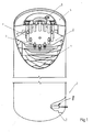
- Fig. 1 shows an embodiment of a latent heat storage in a partially sectioned view.
- the latent heat storage device has a storage container 1, which with a not shown phase change material (PCM) is filled, which encloses a heat exchanger 2.
- the heat exchanger 2 has a plurality of tubes 3, which are arranged distributed circumferentially around a central axis.
- the tubes 3 of the heat exchanger 2 extend through a stack 4 of plates.
- the plate stack 4 serves to increase the effective heat transfer surface.
- On the cover part 5 of the container is a return port 6 for discharging a liquid heat carrier and the bottom part 7, not shown, flow connection for supplying the heat carrier. In the operating position, the return port 6 is at the top and the supply port at the bottom.
- a device 8 is provided, which is arranged in the lower half in use, preferably in the lower third of the storage container 1, more preferably at the bottom of the storage container 1.
- the device 8 for triggering the crystallization is shown only hinted.
- Fig. 2 shows the device 8 for triggering the crystallization in a sectional view.
- the device 8 for triggering the crystallization has a first heat sink 9 and a second heat sink 10, each forming one half of the housing 11 of the device 8.
- Both heat sinks 9, 10 are substantially cylindrical metal body, whose end faces face each other.
- Fig. 3 shows one half of the device 8 for triggering the crystallization.
- the cylindrical cooling bodies 9, 10 At the mutually facing end faces, the cylindrical cooling bodies 9, 10 each have two mutually opposite lugs 12.
- the heat sinks 9, 10 are screwed together, their end faces being spaced apart. The screws, not shown, are located in bores 13 in the heat sinks 9, 10.
- a second Peltier element 15 is arranged on the end face of the first heat sink 9, a first Peltier element 14 and on the opposite end face of the second of the heat sink 10, a second Peltier element 15 is arranged.
- the plate-shaped, in particular square Peltier elements 14, 15 each have a ceramic plate with a first and a second contact surface 14A, 14B and 15A, 15B on the top and bottom, respectively, the first Contact surface 14A with the respective heat sink 9, 10 is in thermal contact, so that the heat energy can be dissipated via the heat sink in the phase change material.
- the second contact surfaces 14B, 15B of the Peltier elements 14, 15 are arranged at a distance from one another.
- the gap 16 between the Peltier elements 14, 15 has a gap width, which in the present embodiment is between 0.3 and 0.5 mm, in particular 0.4 mm.
- a plurality of metallic bodies 17 are arranged, which are in thermal contact with the second contact surfaces 14B, 15B of the Peltier elements 14, 15.
- the metallic bodies 18 are parallel metal wires or metal threads 18, preferably made of stainless steel.
- the metal wires 18 or - threads are preferably glued to at least the contact surface of a Peltier element.
- Between the metal wires or filaments 18 are channels 19 into which the phase change material can pass.
- the channels 19 are in turn via the openings 20 with the interior of the storage container 1 in connection, which are formed between the two heat sinks 9, 10.
- a tubular fastening element 21 is attached, with which the device 8 is attached to trigger the crystallization on the housing wall of the storage container 1.
- the tubular fastening element 21 serves as a cable guide for the connecting cable, not shown, of the two Peltier elements 14, 15.
- the mutually facing contact surfaces 14 B, 15 B of the Peltier elements 14, 15 cool down. Thereby, the phase change material located in the channels 19 between the metallic bodies 17 is cooled down to a temperature sufficiently low that spontaneous crystallization begins in the phase change material in contact with the metallic bodies.
- the embodiment described above is characterized by a safe initiation of crystallization and a simple production.
- the production is simple in that the stainless steel wires 18 or threads can be arranged between the Peltier elements 14, 15 as a distancing elements without much effort.
- Fig. 5 shows an embodiment in which in the gap 16 between the first and second Peltier element 14, 15, a plate-shaped metal body 22 is arranged, which is provided with grooves or grooves 23.
- the grooves or grooves 23 may be provided on the top and / or bottom of the metal body 22 to form the channels 19 into which the phase change material is to pass.
- the plate-shaped metal body 22 is preferably a stainless steel plate.
- Fig. 6 shows a further embodiment in which the metallic body 17 is a meandering metal body 23.
- the metallic body 17 is a wave-shaped metal body 24.
- longitudinal channels 19 are again formed for the phase change material.
Landscapes
- Chemical & Material Sciences (AREA)
- Physics & Mathematics (AREA)
- Thermal Sciences (AREA)
- Crystallography & Structural Chemistry (AREA)
- Chemical Kinetics & Catalysis (AREA)
- Engineering & Computer Science (AREA)
- Mechanical Engineering (AREA)
- General Engineering & Computer Science (AREA)
- Physical Or Chemical Processes And Apparatus (AREA)
Abstract
Description
- Die Erfindung betrifft einen Latentwärmespeicher mit einem Speicherbehälter zur Aufnahme eines Phasenwechselmaterials und einer Vorrichtung zur Auslösung einer Kristallisation in dem Phasenwechselmaterial.
- In solarthermischen Anlagen finden zum Speichern von Solarenergie Latentwärmespeicher Verwendung, die über einen Speicherbehälter zur Aufnahme eines Wärmespeichermediums verfügen. In dem Speicherbehälter ist ein Wärmetauscher angeordnet, der mit einem Vorlauf zum Zuführen eines Wärmeträgermediums und einem Rücklauf zum Abführen des Wärmeträgermediums verbunden ist.
- Die bekannten Latentwärmespeicher können durch Zufuhr von Wärme aufgeladen und durch Abfuhr der gespeicherten Wärme entladen werden. Die bekannten Wärmespeichersysteme verfügen zum Speichern der Wärmeenergie über mehrere Latentwärmespeicher.
- Als Wärmespeichermedium kann ein Phasenwechselmaterial (PCM) Verwendung finden, das zum Speichern der solaren Wärme die Enthalpie reversibler thermodynamischer Zustandsänderungen ausnutzt. Ein bekanntes Phasenwechselmaterial ist beispielsweise Natriumacetat-Trihydrat, das eine hohe Schmelzenthalpie und einen relativ geringen Preis hat. Beim Laden des Latentwärmespeichers geht das Phasenwechselmaterial von einem festen Aggregatzustand in einen flüssigen Aggregatzustand über. Natriumacetat-Trihydrat beispielsweise wird bei einer Schmelztemperatur von 58 °C verflüssigt. Beim Abkühlen bleibt das Salzhydrat als unterkühlte Schmelze in einem metastabilen Zustand flüssig. Wenn eine Kristallisation in der unterkühlten Schmelze ausgelöst wird, erwärmt sich das Salzhydrat auf eine Temperatur von 58 °C, wobei die latente Wärme wieder freigegeben wird.
- Ein Wärmespeichersystem für eine solartechnische Anlage ist aus der
EP 2 273 226 A1 bekannt. Das Wärmespeichersystem umfasst eine Mehrzahl von Wärmespeicher-Behältern, die nacheinander aufgeladen oder entladen werden können. Die einzelnen Wärmespeicher-Behälter sind über ein Leitungssystem miteinander verbunden. Zur Steuerung des Zu- bzw. Abflusses des Wärmeträgermediums sind in den Zuführ- und Abführleitungen Ventile angeordnet, die von einer Steuereinheit angesteuert werden. Die Steuerung erlaubt eine Auf- bzw. Entladung der einzelnen Behälter. - Bei den bekannten Wärmespeichersystemen besteht die Gefahr einer unbeabsichtigten Auslösung der Kristallisation in dem Phasenwechselmaterial, so dass der Latentwärmespeicher zu einem Zeitpunkt entladen wird, zu dem die Wärme nicht gebraucht wird. Für einen störungsfreien Betrieb eines Wärmespeichersystems ist daher die sichere Auslösung der Kristallisation zu einem bestimmten Zeitpunkt von entscheidender Bedeutung.
- Die
DE 10 2010 046 243 A1 beschreibt eine Vorrichtung zur Auslösung der Kristallisation für einen Latentwärmespeicher, die über ein mechanisch verformbares Auslöseelement und einen Aktivierungsmechanismus verfügt. Das Auslösungselement ist als ein Plättchen ausgebildet, das nach Betätigung des Aktivierungsmechanismus schlagartig von einer Form in eine andere Form übergeht. Der Aktivierungsmechanismus weist eine elektrische, elektromagnetische, pneumatische oder piezoelektrische Antriebseinheit auf. - Der Erfindung liegt die Aufgabe zugrunde, einen Latentwärmespeicher für eine solarthermische Anlage zu schaffen, der über eine Vorrichtung zur Auslösung der Kristallisation in dem Phasenwechselmaterial verfügt, die den Kristallisationsprozess sicher in Gang setzt und sich in großen Stückzahlen bei verhältnismäßig geringen Produktionskosten herstellen lässt.
- Die Lösung dieser Aufgabe erfolgt erfindungsgemäß mit den Merkmalen des Patentanspruchs 1. Die Gegenstände der Unteransprüche betreffen vorteilhafte Ausführungsformen der Erfindung.
- Die Vorrichtung zur Auslösung der Kristallisation des erfindungsgemäßen Latentwärmespeichers weist ein erstes Peltier-Element und ein zweites Peltier-Element auf, die unter Bildung eines Spaltes zur Aufnahme des Phasenwechselmaterials im Abstand zueinander angeordnet sind. Mit den beiden Peltier-Elementen kann bei einer kompakten Bauform der Vorrichtung zur Auslösung der Kristallisation eine Abkühlung des Phasenwechselmaterials auf eine Temperatur erreicht werden, die so niedrig ist, dass eine Kristallisation ausgelöst wird. Der Spalt zwischen den Peltier-Elementen bildet ein Kompartiment, in den das Phasenwechselmaterial fließen kann. In diesem Kompartiment kann das Phasenwechselmaterial in verhältnismäßig kurzer Zeit auf die erforderliche Temperatur abgekühlt werden. Die beidseitige Anordnung der Peltier-Elemente schafft einen besonders guten Wärmeübergang.
- Wenn als Phasenwechselmaterial Natriumacetat-Trihydrat verwendet wird, sollte die Temperatur, auf die das Phasenwechselmaterial abgekühlt wird, zwischen -10°C und-30°C, vorzugsweise -20°C bis -30°C liegen.
- In der Praxis ist die Abkühlung des Phasenwechselmaterials in dem Spalt zwischen dem ersten und zweiten Peltier-Element für eine sichere Auslösung der Kristallisation allein nicht ausreichend. Es hat sich in Versuchen gezeigt, dass eine sichere Auslösung der Kristallisation dann gewährleistet ist, wenn in dem Spalt zwischen dem ersten und zweiten Peltier-Element unter Bildung von Kanälen in dem Spalt, durch die das Phasenwechselmaterial in den Spalt fließen kann, mindestens ein metallischer Körper angeordnet ist, der im thermischen Kontakt mit dem ersten und zweiten Peltier-Element ist. Es hat sich gezeigt, dass für die spontane Kristallisation bei der Abkühlung des Phasenwechselmaterials die Spaltbildung mit den Kanälen in Verbindung mit der Anwesenheit des Werkstoffs Metall entscheidend ist.
- Die Versuche haben gezeigt, dass grundsätzlich sämtliche metallischen Körper verwendet werden können. Allerdings sind nur solche Metalle geeignet, die von dem Phasenwechselmaterial nicht chemisch angegriffen werden. Als Werkstoff für den mindestens einen Metallkörper hat sich insbesondere Edelstahl als besonders vorteilhaft erwiesen, der bei ausreichender chemischer Resistenz kostengünstig ist.
- Die Dicke des mindestens einen metallischen Körpers entspricht vorzugsweise der Höhe des Kompartiments, so dass der mindestens eine metallische Körper die Anlageflächen der beiden Peltier-Elemente kontaktiert.
- Bei der Ausführungsform, bei der in dem Spalt mehrere metallische Körper angeordnet sind, ist die Form der metallischen Körper nicht entscheidend, um in dem Kompartiment Kanäle auszubilden. Die metallischen Körper können beispielsweise Körper mit einem runden oder eckigen Querschnitt sein, beispielsweise einen kreisrunden oder rechteckförmigen Querschnitt haben. Als metallische Körper können beispielsweise auch Metallkugeln verwendet werden, die im Abstand zueinander angeordnet sind. Die metallischen Körper können sich über die gesamte Länge bzw. Breite oder nur einen Teil der Länge bzw. Breite des Kompartiments erstrecken.
- Eine bevorzugte Ausführungsform sieht vor, dass in dem Spalt zwischen den Peltier-Elementen mehrere im Abstand zueinander angeordnet Metalldrähte oder Metallfäden angeordnet sind. In Versuchen hat sich gezeigt, dass die Anordnung der Metalldrähte in dem Spalt bei einer Abkühlung des Phasenwechselmaterials zu einer spontane Auslösung der Kristallisation führt. Die Metalldrähte- oder -fäden sind vorzugsweise chemisch resistente Edelstahldrähte oder -fäden. In diesem Zusammenhang werden unter Drähten oder Fäden nicht nur langestrecke Körper mit einem kreisförmigen, sondern auch nichtkreisförmigen Querschnitt verstanden, beispielsweise stabförmige metallische Körper mit einem beispielsweise rechteckförmigen Querschnitt.
- Eine besonders bevorzugte Ausführungsform sieht eine parallele Anordnung der Metalldrähte- oder -fäden in dem Spalt vor, so dass zwischen den Drähten oder Fäden längslaufende Kanäle ausgebildet werden, durch die Phasenwechselmaterial leicht in den Spalt fließen kann.
- Die Spaltbreite sollte so bemessen sein, dass sich in dem Spalt keine Luftblasen ansammeln können. Als geeignete Spaltbreite hat sich ein Abstand zwischen dem ersten und zweiten Peltier-Element erwiesen, der zwischen 0,2 bis 0,6 mm, vorzugsweise zwischen 0,3 und 0,5 mm, insbesondere 0,4 mm, liegt.
- Der mindestens eine metallische Körper ist mit mindestens einem der Peltier-Elemente vorzugsweise verklebt. Zum Verkleben wird vorzugsweise ein Kleber verwendet, der eine hohe Wärmeleitkapazität hat. Es ist aber auch möglich, dass der mindestens eine metallische Körper zwischen den beiden Peltier-Elementen klemmend fixiert ist.
- Bei der alternativen Ausführungsform, bei der in dem Spalt ein metallischer Körper angeordnet ist, kann der metallische Körper Bohrungen und/oder Rillen aufweisen, die die Kanäle zwischen dem ersten und zweiten Peltier-Element ausbilden. Der metallische Körper kann aber auch derart geformt sein, dass zwischen dem ersten und zweiten Peltier-Element Kanäle ausgebildet werden. Eine bevorzugte Ausführungsform sieht einen mäanderförmigen oder wellenförmigen Metallkörper zwischen den Peltier-Elementen vor.
- Eine besonders bevorzugte Ausführungsform sieht vor, dass die einander abgewandten Seiten des ersten und zweiten Peltier-Elements jeweils mit einem Kühlkörper im thermischen Kontakt sind. Dadurch kann eine ausreichend hohe Wärmemenge abgeführt werden, so dass sich mit den Peltier-Elementen eine Temperaturdifferenz erreichen lässt, die für die Auslösung der Kristallisation ausreichend ist.
- Bei einer weiteren besonders bevorzugten Ausführungsform ist der Kühlkörper des ersten Peltier-Elements und der Kühlkörper des zweiten Peltier-Elements als eine erste und eine zweite Gehäusehälfte des Gehäuses der Vorrichtung zur Auslösung der Kristallisation ausgebildet. Die Kühlkörper sind vorzugsweise miteinander verschraubt, wobei in dem ersten und/oder zweiten Kühlkörper mindestens ein zu dem Spalt zwischen den Peltier-Elementen führender Durchbruch vorgesehen ist, durch den das Phasenwechselmaterial in die Kanäle des Spaltes strömen kann. Damit bildet die Vorrichtung zur Auslösung der Kristallisation eine Einheit, die leicht in den Speicherbehälter eingebaut werden kann. Das Gehäuse weist vorzugsweise ein Befestigungselement auf, mit dem die Vorrichtung an dem Speicherbehälter befestigt ist. Das Befestigungselement ist vorzugsweise als eine Leitungsführung ausgebildet, in der die Anschlussleitungen für das erste und zweite Peltier-Element geführt sind.
- Die Vorrichtung zur Auslösung der Kristallisation ist vorzugsweise in der in der Gebrauchslage unteren Hälfte des Speicherbehälters, besonders bevorzugt im unteren Drittel des Speicherbehälters, angeordnet, in dem das Phasenwechselmaterial im Allgemeinen eine niedrigere Temperatur hat.
- Nachfolgend werden verschiedene Ausführungsbeispiele der Erfindung unter Bezugnahme auf die Zeichnungen näher erläutert.
- Es zeigen:
- Fig. 1
- einen erfindungsgemäßen Latentwärmespeicher eines Wärmespeichersystems in teilweiser geschnittener Darstellung,
- Fig. 2
- die Vorrichtung zur Auslösung der Kristallisation des erfindungsgemäßen Latentwärmespeichers in geschnittener Darstellung,
- Fig. 3
- den Ausschnitt A von
Fig. 2 in vergrößerter Darstellung, - Fig. 4
- eine Hälfte der Vorrichtung zur Auslösung der Kristallisation in geschnittener Darstellung,
- Fig. 5
- einen Ausschnitt eines zweiten Ausführungsbeispiels der Vorrichtung zur Auslösung der Kristallisation,
- Fig.6
- einen Ausschnitt eines dritten Ausführungsbeispiels der Vorrichtung zur Auslösung der Kristallisation und
- Fig. 7
- einen Ausschnitt eines vierten Ausführungsbeispiels der Vorrichtung zur Auslösung der Kristallisation.
-
Fig. 1 zeigt ein Ausführungsbeispiel eines Latentwärmespeichers in teilweise geschnittener Darstellung. Der Latentwärmespeicher weist einen Speicherbehälter 1 auf, der mit einem nicht dargestellten Phasenwechselmaterial (PCM) befüllt ist, das einen Wärmetauscher 2 umschließt. Der Wärmetauscher 2 weist eine Mehrzahl von Rohren 3 auf, die um eine zentrale Achse umfangsmäßig verteilt angeordnet sind. Die Rohre 3 des Wärmetauschers 2 erstrecken sich durch einen Stapel 4 von Platten. Der Plattenstapel 4 dient der Vergrößerung der wirksamen Wärmeübergangsfläche. Am Deckelteil 5 des Behälters befindet sich ein Rücklauf-Anschluss 6 zum Abführen eines flüssigen Wärmeträgers und am Bodenteil 7 ein nicht dargestellter Vorlauf-Anschluss zum Zuführen des Wärmeträgers. In der Gebrauchslage liegt der Rücklauf-Anschluss 6 oben und der Vorlauf-Anschluss unten. - Zur Auslösung des Kristallisationsprozesses in dem Phasenwechselmaterial ist eine Vorrichtung 8 vorgesehen, die in der in der Gebrauchslage unteren Hälfte, vorzugsweise im unteren Drittel des Speicherbehälters 1, besonders bevorzugt am Boden des Speicherbehälters 1 angeordnet ist. In
Fig. 1 ist die Vorrichtung 8 zur Auslösung der Kristallisation nur andeutungsweise dargestellt.Fig. 2 zeigt die Vorrichtung 8 zur Auslösung der Kristallisation in geschnittener Darstellung. - Die Vorrichtung 8 zur Auslösung der Kristallisation weist einen ersten Kühlkörper 9 und einen zweiten Kühlkörper 10 auf, die jeweils eine Hälfte des Gehäuses 11 der Vorrichtung 8 bilden. Beide Kühlkörper 9, 10 sind im Wesentlichen zylindrische Metallkörper, deren Stirnflächen einander zugewandt sind.
Fig. 3 zeigt eine Hälfte der Vorrichtung 8 zur Auslösung der Kristallisation. An den einander zugewandten Stirnflächen weisen die zylindrischen Kühlkörper 9, 10 jeweils zwei einander gegenüberliegende Ansätze 12 auf. Die Kühlkörper 9, 10 sind miteinander verschraubt, wobei deren Stirnflächen im Abstand zueinander angeordnet sind. Die nicht dargestellten Schrauben sitzen in Bohrungen 13 in den Kühlkörpern 9, 10. - An der Stirnfläche des ersten Kühlkörpers 9 ist ein erstes Peltier-Element 14 und an der gegenüberliegenden Stirnfläche des zweiten der Kühlkörper 10 ist ein zweites Peltier-Element 15 angeordnet. Die plattenförmigen, insbesondere quadratischen Peltier-Elemente 14, 15 weisen an der Ober- bzw. Unterseite jeweils eine Platte aus Keramik mit einer ersten und zweiten Anlagefläche 14A, 14B bzw. 15A, 15B auf, wobei die erste Anlagefläche 14A mit dem jeweiligen Kühlkörper 9, 10 im thermischen Kontakt ist, so dass die Wärmeenergie über die Kühlkörper in das Phasenwechselmaterial abgeführt werden kann. Die zweiten Anlageflächen 14B, 15B der Peltier-Elemente 14, 15 sind im Abstand zueinander angeordnet. Der Spalt 16 zwischen den Peltier-Elementen 14, 15 hat eine Spaltbreite, die bei dem vorliegenden Ausführungsbeispiel zwischen 0,3 und 0,5 mm, insbesondere 0,4 mm, liegt.
- In dem Spalt 16 zwischen den Peltier-Elementen 14, 15 sind mehrere metallische Körper 17 angeordnet, die mit den zweiten Anlageflächen 14B, 15B der Peltier-Elemente 14, 15 in thermischen Kontakt sind. Die metallischen Körper 18 sind parallel verlaufende Metalldrähte oder Metallfäden 18, vorzugsweise aus Edelstahl. Die Metalldrähte 18 oder - fäden sind vorzugsweise mit zumindest der Anlagefläche eines Peltier-Elementes verklebt. Zwischen den Metalldrähten oder -fäden 18 befinden sich Kanäle 19, in die das Phasenwechselmaterial gelangen kann. Die Kanäle 19 stehen wiederum über die Durchbrüche 20 mit dem Inneren des Speicherbehälters 1 in Verbindung, die zwischen den beiden Kühlkörpern 9, 10 ausgebildet sind.
- An der außenliegenden Stirnfläche des ersten Kühlkörpers 9 ist ein rohrförmiges Befestigungselement 21 angebracht, mit dem die Vorrichtung 8 zur Auslösung der Kristallisation an der Gehäusewand des Speicherbehälters 1 befestigt ist. Das rohrförmige Befestigungselement 21 dient gleichsam als Kabelführung für das nicht dargestellte Anschlusskabel der beiden Peltier-Elemente 14, 15.
- Wenn die beiden Peltier-Elemente 14, 15 mit Strom versorgt werden, kühlen sich die einander zugewandten Anlageflächen 14B, 15B der Peltier-Elemente 14, 15 ab. Dadurch wird das in den Kanälen 19 zwischen den metallischen Körpern 17 befindliche Phasenwechselmaterial auf eine Temperatur abgekühlt, die ausreichend niedrig ist, dass eine spontane Kristallisation in dem Phasenwechselmaterial, das mit den metallischen Körpern in Kontakt ist, einsetzt.
- Die oben beschriebene Ausführungsform zeichnet sich durch eine sichere Auslösung der Kristallisation und eine einfache Herstellung aus. Die Herstellung ist insofern einfach, als sich die Edelstahldrähte 18 oder -fäden ohne großen Aufwand zwischen den Peltier-Elementen 14, 15 als distanzgebende Elemente anordnen lassen.
- Nachfolgend werden alternative Ausführungsformen beschrieben, bei denen nicht mehrere metallische Körper sind, sondern nur ein metallischer Körper 17 zwischen den Peltier-Elementen 14, 15 angeordnet ist, um die Kanäle 19 auszubilden, in denen das Phasenwechselmaterial mit dem metallischen Werkstoff in Kontakt ist. Die einander entsprechenden Teile sind mit den gleichen Bezugszeichen versehen.
-
Fig. 5 zeigt ein Ausführungsbeispiel, bei dem in dem Spalt 16 zwischen dem ersten und zweiten Peltier-Element 14, 15 ein plattenförmiger Metallkörper 22 angeordnet ist, der mit Rillen oder Rinnen 23 versehen ist. Die Rillen oder Rinnen 23 können an der an der Ober und/oder Unterseite des Metallkörpers 22 vorgesehen sein, um die Kanäle 19 auszubilden, in die das Phasenwechselmaterial gelangen soll. Der plattenförmige Metallkörper 22 ist vorzugsweise eine Edelstahlplatte. -
Fig. 6 zeigt ein weiteres Ausführungsbeispiel, bei dem der metallische Körper 17 ein mäanderförmiger Metallkörper 23 ist. Bei dem Ausführungseispiel vonFig. 7 ist der metallische Körper 17 ein wellenförmiger Metallkörper 24. Bei beiden Ausführungsformen werden wieder längslaufende Kanäle 19 für das Phasenwechselmaterial ausgebildet.
Claims (14)
- Latentwärmespeicher mit einem Speicherbehälter (1) zur Aufnahme eines Phasenwechselmaterials und einer Vorrichtung (8) zur Auslösung einer Kristallisation in dem Phasenwechselmaterial,
dadurch gekennzeichnet, dass
die Vorrichtung (8) zur Auslösung einer Kristallisation ein erstes Peltier-Element (14) und ein zweites Peltier-Element (15) aufweist, die unter Bildung eines Spaltes (16) zur Aufnahme des Phasenwechselmaterials im Abstand zueinander angeordnet sind,
wobei in dem Spalt (16) zwischen dem ersten und zweiten Peltier-Element (14, 15) unter Bildung von Kanälen (19) in dem Spalt (16) mindestens ein metallischer Körper (17) angeordnet ist, der im thermischen Kontakt mit dem ersten und zweiten Peltier-Element (14, 15) ist. - Latentwärmespeicher nach Anspruch 1, dadurch gekennzeichnet, dass als metallische Körper (17) in dem Spalt mehrere im Abstand zueinander angeordnet Metalldrähte oder Metallfäden (18) angeordnet sind.
- Latentwärmespeicher nach Anspruch 2, dadurch gekennzeichnet, dass die Metalldrähte oder Metallfäden (18) Edelstahldrähte oder Edelstahlfäden sind.
- Latentwärmespeicher nach Anspruch 2 oder 3, dadurch gekennzeichnet, dass die Metalldrähte oder Metallfäden (18) in dem Spalt zwischen dem ersten und zweiten Peltier-Element (14, 15) parallel zueinander angeordnet sind.
- Latentwärmespeicher nach Anspruch 1, dadurch gekennzeichnet, dass der metallische Körper (17) Bohrungen und/oder Rillen (23) aufweist, die die Kanäle (19) zwischen dem ersten und zweiten Peltier-Element (14, 15) ausbilden.
- Latentwärmespeicher nach Anspruch 1, dadurch gekennzeichnet, dass der metallische Körper (17) derart geformt ist, dass die Kanäle (19) zwischen dem ersten und zweiten Peltier-Element (14, 15) ausgebildet werden.
- Latentwärmespeicher nach Anspruch 6, dadurch gekennzeichnet, dass der metallische Körper (17) ein mäanderförmiger Metallkörper (23) oder wellenförmiger Metallkörper (24) ist.
- Latentwärmespeicher nach einem der Ansprüche 1 bis 7, dadurch gekennzeichnet, dass die Breite des Spaltes (16) zwischen dem ersten und zweiten Peltier-Element (14, 15) zwischen 0,2 bis 0,6 mm, vorzugsweise zwischen 0,3 und 0,5 mm, insbesondere 0,4 mm, ist.
- Latentwärmespeicher nach einem der Ansprüche 1 bis 8, dadurch gekennzeichnet, dass der mindestens eine metallische Körper (17) mit dem ersten und zweiten Peltier-Element (14, 15) verklebt ist.
- Latentwärmespeicher nach einem der Ansprüche 1 bis 9, dadurch gekennzeichnet, dass die einander abgewandten Seiten des ersten und zweiten Peltier-Elements (14, 15) jeweils mit einem Kühlkörper (9, 10) im thermischen Kontakt sind.
- Latentwärmespeicher nach einem der Ansprüche 1 bis 10, dadurch gekennzeichnet, dass der Kühlkörper (9) des ersten Peltier-Elements (14) und der Kühlkörper (10) des zweiten Peltier-Elements (15) als eine erste und eine zweite Gehäusehälfte ausgebildet sind, die miteinander verschraubt sind, wobei in dem ersten und/oder zweiten Kühlkörper (9, 10) mindestens ein zu dem Spalt (16) zwischen den Peltier-Elementen (14, 15) führender Durchbruch (20) vorgesehen ist.
- Latentwärmespeicher nach einem der Ansprüche 1 bis 11, dadurch gekennzeichnet, dass das Gehäuse (11) ein Befestigungselement (21) aufweist, mit dem die Vorrichtung (8) zur Einleitung der Kristallisation an dem Speicherbehälter (1) befestigt ist.
- Latentwärmespeicher nach Anspruch 12, dadurch gekennzeichnet, dass das Befestigungselement (21) als eine Leitungsführung ausgebildet ist, in der die Anschlussleitungen für das erste und zweite Peltier-Element (14, 15) geführt sind.
- Latentwärmespeicher nach einem der Ansprüche 1 bis 13, dadurch gekennzeichnet, dass die Vorrichtung (8) zur Auslösung der Kristallisation in der in der Gebrauchslage unteren Hälfte des Speicherbehälters (1) angeordnet ist.
Priority Applications (3)
| Application Number | Priority Date | Filing Date | Title |
|---|---|---|---|
| PL15154761T PL3056848T3 (pl) | 2015-02-11 | 2015-02-11 | Zasobnik ciepła utajonego z urządzeniem do inicjacji krystalizacji |
| EP15154761.9A EP3056848B1 (de) | 2015-02-11 | 2015-02-11 | Latentwärmespeicher mit einer Vorrichtung zur Auslösung der Kristallisation |
| DK15154761.9T DK3056848T3 (en) | 2015-02-11 | 2015-02-11 | Latent heat bearing with a device for triggering crystallization. |
Applications Claiming Priority (1)
| Application Number | Priority Date | Filing Date | Title |
|---|---|---|---|
| EP15154761.9A EP3056848B1 (de) | 2015-02-11 | 2015-02-11 | Latentwärmespeicher mit einer Vorrichtung zur Auslösung der Kristallisation |
Publications (2)
| Publication Number | Publication Date |
|---|---|
| EP3056848A1 true EP3056848A1 (de) | 2016-08-17 |
| EP3056848B1 EP3056848B1 (de) | 2018-01-31 |
Family
ID=52465276
Family Applications (1)
| Application Number | Title | Priority Date | Filing Date |
|---|---|---|---|
| EP15154761.9A Not-in-force EP3056848B1 (de) | 2015-02-11 | 2015-02-11 | Latentwärmespeicher mit einer Vorrichtung zur Auslösung der Kristallisation |
Country Status (3)
| Country | Link |
|---|---|
| EP (1) | EP3056848B1 (de) |
| DK (1) | DK3056848T3 (de) |
| PL (1) | PL3056848T3 (de) |
Cited By (2)
| Publication number | Priority date | Publication date | Assignee | Title |
|---|---|---|---|---|
| DE102017125669A1 (de) | 2017-11-03 | 2019-05-09 | H.M. Heizkörper GmbH & Co. KG | Wärmespeicher |
| US10352311B2 (en) * | 2016-06-02 | 2019-07-16 | The United States Of America, As Represented By The Secretary Of Agriculture | Cryogenic trap system |
Citations (6)
| Publication number | Priority date | Publication date | Assignee | Title |
|---|---|---|---|---|
| DE3044202A1 (de) * | 1980-11-24 | 1982-05-27 | Alfred Schneider KG, 7630 Lahr | Verfahren und vorrichtung zum einbringen von kristallisationskeimen in ein fluessiges latentwaermespeichermedium |
| DE10303498A1 (de) * | 2003-01-30 | 2004-08-12 | Robert Bosch Gmbh | Vorrichtung und Verfahren zur Kühlung des Wärmematerials eines Latentwärmespeichers |
| JP2007285549A (ja) * | 2006-04-13 | 2007-11-01 | Toyota Motor Corp | 蓄熱装置 |
| EP2273226A1 (de) | 2009-03-09 | 2011-01-12 | Rawema Countertrade Handelsgesellschaft mbH | Wärmespeichersystem |
| DE102010046243A1 (de) | 2010-09-22 | 2012-03-22 | Rawema Countertrade Handelsgesellschaft Mbh | Auslöseeinheit |
| DE102013220281A1 (de) * | 2013-10-08 | 2015-04-09 | Robert Bosch Gmbh | Vorrichtung und Verfahren zum Vorheizen von Motoröl für die Startphase eines Verbrennungsmotors |
-
2015
- 2015-02-11 DK DK15154761.9T patent/DK3056848T3/en active
- 2015-02-11 EP EP15154761.9A patent/EP3056848B1/de not_active Not-in-force
- 2015-02-11 PL PL15154761T patent/PL3056848T3/pl unknown
Patent Citations (6)
| Publication number | Priority date | Publication date | Assignee | Title |
|---|---|---|---|---|
| DE3044202A1 (de) * | 1980-11-24 | 1982-05-27 | Alfred Schneider KG, 7630 Lahr | Verfahren und vorrichtung zum einbringen von kristallisationskeimen in ein fluessiges latentwaermespeichermedium |
| DE10303498A1 (de) * | 2003-01-30 | 2004-08-12 | Robert Bosch Gmbh | Vorrichtung und Verfahren zur Kühlung des Wärmematerials eines Latentwärmespeichers |
| JP2007285549A (ja) * | 2006-04-13 | 2007-11-01 | Toyota Motor Corp | 蓄熱装置 |
| EP2273226A1 (de) | 2009-03-09 | 2011-01-12 | Rawema Countertrade Handelsgesellschaft mbH | Wärmespeichersystem |
| DE102010046243A1 (de) | 2010-09-22 | 2012-03-22 | Rawema Countertrade Handelsgesellschaft Mbh | Auslöseeinheit |
| DE102013220281A1 (de) * | 2013-10-08 | 2015-04-09 | Robert Bosch Gmbh | Vorrichtung und Verfahren zum Vorheizen von Motoröl für die Startphase eines Verbrennungsmotors |
Cited By (2)
| Publication number | Priority date | Publication date | Assignee | Title |
|---|---|---|---|---|
| US10352311B2 (en) * | 2016-06-02 | 2019-07-16 | The United States Of America, As Represented By The Secretary Of Agriculture | Cryogenic trap system |
| DE102017125669A1 (de) | 2017-11-03 | 2019-05-09 | H.M. Heizkörper GmbH & Co. KG | Wärmespeicher |
Also Published As
| Publication number | Publication date |
|---|---|
| EP3056848B1 (de) | 2018-01-31 |
| PL3056848T3 (pl) | 2018-08-31 |
| DK3056848T3 (en) | 2018-03-19 |
Similar Documents
| Publication | Publication Date | Title |
|---|---|---|
| DE2242581C3 (de) | Hohlplatte für Gebäudewandungen mit variabler Wärmeleitfähigkeit | |
| EP0662209B1 (de) | Thermoelektrische heiz- oder kühlvorrichtung | |
| EP3655631B1 (de) | Energiespeicher zum speichern von elektrischer energie als wärme und verfahren hierzu | |
| DE69424761T2 (de) | Kühlungsapparat vom Wärmerohrtyp | |
| EP0454017B1 (de) | Hochtemperaturspeicherbatterie | |
| DE102011119174A1 (de) | Vapor Chamber | |
| EP4046231B1 (de) | Gehäusevorrichtung für traktionsbatterie mit fluidbasierter kühlung mit verdampfungsvorrichtung mit mikrokanälen | |
| AT12048U1 (de) | Vorrichtung zur übertragung von wärme | |
| EP0293361A1 (de) | Transport- und Aufbewahrungseinrichtung für thermosensible Produkte | |
| WO2010003755A1 (de) | Vorrichtung und verfahren zur kühlung von bauteilen mittels magnetisierbarem phasenwechselmaterial | |
| DE202010002352U1 (de) | Elektrochemischer Energiespeicher | |
| DE102018124663A1 (de) | Dosiersystem mit Dosierstoff-Kühleinrichtung | |
| EP0312737B1 (de) | Elektrisch gesteuerte Armatur | |
| EP2696159B1 (de) | Wärmeaustauscher und Verfahren zur Benetzung von Wärmeaustauschern | |
| EP3056848B1 (de) | Latentwärmespeicher mit einer Vorrichtung zur Auslösung der Kristallisation | |
| EP1098157B1 (de) | Latentwärmespeicher | |
| DE102010060717A1 (de) | Wärmeverteiler und dessen Verwendung | |
| DE102013206868A1 (de) | Verfahren zur Kühlung eines Halbleiterbauteils und Vorrichtung | |
| AT516385B1 (de) | Temperiereinheit für ein gasförmiges oder flüssiges Medium | |
| EP2562485A2 (de) | Medienheizer | |
| AT521295A1 (de) | Akkumulator | |
| EP3758130A1 (de) | Aufnahmevorrichtung zur aufnahme und kühlung von einschubmodulen | |
| DE202005013835U1 (de) | Vorrichtung zum schnellen Aufheizen, Abkühlen, Verdampfen oder Kondensieren von Fluiden | |
| DE102018105037B4 (de) | Kühlvorrichtung für die Kühlung eines Batteriemoduls einer Batterievorrichtung eines Fahrzeugs | |
| WO2016207153A1 (de) | Temperiereinheit für ein gasförmiges oder flüssiges medium |
Legal Events
| Date | Code | Title | Description |
|---|---|---|---|
| PUAI | Public reference made under article 153(3) epc to a published international application that has entered the european phase |
Free format text: ORIGINAL CODE: 0009012 |
|
| AK | Designated contracting states |
Kind code of ref document: A1 Designated state(s): AL AT BE BG CH CY CZ DE DK EE ES FI FR GB GR HR HU IE IS IT LI LT LU LV MC MK MT NL NO PL PT RO RS SE SI SK SM TR |
|
| AX | Request for extension of the european patent |
Extension state: BA ME |
|
| STAA | Information on the status of an ep patent application or granted ep patent |
Free format text: STATUS: REQUEST FOR EXAMINATION WAS MADE |
|
| 17P | Request for examination filed |
Effective date: 20170201 |
|
| RBV | Designated contracting states (corrected) |
Designated state(s): AL AT BE BG CH CY CZ DE DK EE ES FI FR GB GR HR HU IE IS IT LI LT LU LV MC MK MT NL NO PL PT RO RS SE SI SK SM TR |
|
| RIC1 | Information provided on ipc code assigned before grant |
Ipc: A61F 7/02 20060101ALN20170711BHEP Ipc: B01D 9/00 20060101ALI20170711BHEP Ipc: F28D 20/02 20060101AFI20170711BHEP Ipc: F28F 1/32 20060101ALN20170711BHEP |
|
| GRAP | Despatch of communication of intention to grant a patent |
Free format text: ORIGINAL CODE: EPIDOSNIGR1 |
|
| STAA | Information on the status of an ep patent application or granted ep patent |
Free format text: STATUS: GRANT OF PATENT IS INTENDED |
|
| INTG | Intention to grant announced |
Effective date: 20170829 |
|
| GRAS | Grant fee paid |
Free format text: ORIGINAL CODE: EPIDOSNIGR3 |
|
| GRAA | (expected) grant |
Free format text: ORIGINAL CODE: 0009210 |
|
| STAA | Information on the status of an ep patent application or granted ep patent |
Free format text: STATUS: THE PATENT HAS BEEN GRANTED |
|
| AK | Designated contracting states |
Kind code of ref document: B1 Designated state(s): AL AT BE BG CH CY CZ DE DK EE ES FI FR GB GR HR HU IE IS IT LI LT LU LV MC MK MT NL NO PL PT RO RS SE SI SK SM TR |
|
| REG | Reference to a national code |
Ref country code: GB Ref legal event code: FG4D Free format text: NOT ENGLISH Ref country code: CH Ref legal event code: EP |
|
| REG | Reference to a national code |
Ref country code: AT Ref legal event code: REF Ref document number: 967772 Country of ref document: AT Kind code of ref document: T Effective date: 20180215 |
|
| REG | Reference to a national code |
Ref country code: IE Ref legal event code: FG4D Free format text: LANGUAGE OF EP DOCUMENT: GERMAN |
|
| REG | Reference to a national code |
Ref country code: DE Ref legal event code: R096 Ref document number: 502015002926 Country of ref document: DE |
|
| REG | Reference to a national code |
Ref country code: DK Ref legal event code: T3 Effective date: 20180315 |
|
| REG | Reference to a national code |
Ref country code: FR Ref legal event code: PLFP Year of fee payment: 4 |
|
| REG | Reference to a national code |
Ref country code: CH Ref legal event code: NV Representative=s name: AMMANN PATENTANWAELTE AG BERN, CH |
|
| REG | Reference to a national code |
Ref country code: NL Ref legal event code: MP Effective date: 20180131 |
|
| REG | Reference to a national code |
Ref country code: LT Ref legal event code: MG4D |
|
| PG25 | Lapsed in a contracting state [announced via postgrant information from national office to epo] |
Ref country code: ES Free format text: LAPSE BECAUSE OF FAILURE TO SUBMIT A TRANSLATION OF THE DESCRIPTION OR TO PAY THE FEE WITHIN THE PRESCRIBED TIME-LIMIT Effective date: 20180131 Ref country code: NL Free format text: LAPSE BECAUSE OF FAILURE TO SUBMIT A TRANSLATION OF THE DESCRIPTION OR TO PAY THE FEE WITHIN THE PRESCRIBED TIME-LIMIT Effective date: 20180131 Ref country code: LT Free format text: LAPSE BECAUSE OF FAILURE TO SUBMIT A TRANSLATION OF THE DESCRIPTION OR TO PAY THE FEE WITHIN THE PRESCRIBED TIME-LIMIT Effective date: 20180131 Ref country code: HR Free format text: LAPSE BECAUSE OF FAILURE TO SUBMIT A TRANSLATION OF THE DESCRIPTION OR TO PAY THE FEE WITHIN THE PRESCRIBED TIME-LIMIT Effective date: 20180131 Ref country code: FI Free format text: LAPSE BECAUSE OF FAILURE TO SUBMIT A TRANSLATION OF THE DESCRIPTION OR TO PAY THE FEE WITHIN THE PRESCRIBED TIME-LIMIT Effective date: 20180131 Ref country code: NO Free format text: LAPSE BECAUSE OF FAILURE TO SUBMIT A TRANSLATION OF THE DESCRIPTION OR TO PAY THE FEE WITHIN THE PRESCRIBED TIME-LIMIT Effective date: 20180430 |
|
| PG25 | Lapsed in a contracting state [announced via postgrant information from national office to epo] |
Ref country code: SE Free format text: LAPSE BECAUSE OF FAILURE TO SUBMIT A TRANSLATION OF THE DESCRIPTION OR TO PAY THE FEE WITHIN THE PRESCRIBED TIME-LIMIT Effective date: 20180131 Ref country code: LV Free format text: LAPSE BECAUSE OF FAILURE TO SUBMIT A TRANSLATION OF THE DESCRIPTION OR TO PAY THE FEE WITHIN THE PRESCRIBED TIME-LIMIT Effective date: 20180131 Ref country code: RS Free format text: LAPSE BECAUSE OF FAILURE TO SUBMIT A TRANSLATION OF THE DESCRIPTION OR TO PAY THE FEE WITHIN THE PRESCRIBED TIME-LIMIT Effective date: 20180131 Ref country code: IS Free format text: LAPSE BECAUSE OF FAILURE TO SUBMIT A TRANSLATION OF THE DESCRIPTION OR TO PAY THE FEE WITHIN THE PRESCRIBED TIME-LIMIT Effective date: 20180531 Ref country code: BG Free format text: LAPSE BECAUSE OF FAILURE TO SUBMIT A TRANSLATION OF THE DESCRIPTION OR TO PAY THE FEE WITHIN THE PRESCRIBED TIME-LIMIT Effective date: 20180430 |
|
| PG25 | Lapsed in a contracting state [announced via postgrant information from national office to epo] |
Ref country code: MT Free format text: LAPSE BECAUSE OF FAILURE TO SUBMIT A TRANSLATION OF THE DESCRIPTION OR TO PAY THE FEE WITHIN THE PRESCRIBED TIME-LIMIT Effective date: 20180131 |
|
| PG25 | Lapsed in a contracting state [announced via postgrant information from national office to epo] |
Ref country code: AL Free format text: LAPSE BECAUSE OF FAILURE TO SUBMIT A TRANSLATION OF THE DESCRIPTION OR TO PAY THE FEE WITHIN THE PRESCRIBED TIME-LIMIT Effective date: 20180131 Ref country code: RO Free format text: LAPSE BECAUSE OF FAILURE TO SUBMIT A TRANSLATION OF THE DESCRIPTION OR TO PAY THE FEE WITHIN THE PRESCRIBED TIME-LIMIT Effective date: 20180131 Ref country code: IT Free format text: LAPSE BECAUSE OF FAILURE TO SUBMIT A TRANSLATION OF THE DESCRIPTION OR TO PAY THE FEE WITHIN THE PRESCRIBED TIME-LIMIT Effective date: 20180131 Ref country code: EE Free format text: LAPSE BECAUSE OF FAILURE TO SUBMIT A TRANSLATION OF THE DESCRIPTION OR TO PAY THE FEE WITHIN THE PRESCRIBED TIME-LIMIT Effective date: 20180131 |
|
| REG | Reference to a national code |
Ref country code: DE Ref legal event code: R097 Ref document number: 502015002926 Country of ref document: DE |
|
| REG | Reference to a national code |
Ref country code: IE Ref legal event code: MM4A |
|
| REG | Reference to a national code |
Ref country code: BE Ref legal event code: MM Effective date: 20180228 |
|
| PG25 | Lapsed in a contracting state [announced via postgrant information from national office to epo] |
Ref country code: CZ Free format text: LAPSE BECAUSE OF FAILURE TO SUBMIT A TRANSLATION OF THE DESCRIPTION OR TO PAY THE FEE WITHIN THE PRESCRIBED TIME-LIMIT Effective date: 20180131 Ref country code: LU Free format text: LAPSE BECAUSE OF NON-PAYMENT OF DUE FEES Effective date: 20180211 Ref country code: SM Free format text: LAPSE BECAUSE OF FAILURE TO SUBMIT A TRANSLATION OF THE DESCRIPTION OR TO PAY THE FEE WITHIN THE PRESCRIBED TIME-LIMIT Effective date: 20180131 Ref country code: SK Free format text: LAPSE BECAUSE OF FAILURE TO SUBMIT A TRANSLATION OF THE DESCRIPTION OR TO PAY THE FEE WITHIN THE PRESCRIBED TIME-LIMIT Effective date: 20180131 Ref country code: MC Free format text: LAPSE BECAUSE OF FAILURE TO SUBMIT A TRANSLATION OF THE DESCRIPTION OR TO PAY THE FEE WITHIN THE PRESCRIBED TIME-LIMIT Effective date: 20180131 |
|
| PLBE | No opposition filed within time limit |
Free format text: ORIGINAL CODE: 0009261 |
|
| STAA | Information on the status of an ep patent application or granted ep patent |
Free format text: STATUS: NO OPPOSITION FILED WITHIN TIME LIMIT |
|
| 26N | No opposition filed |
Effective date: 20181102 |
|
| PG25 | Lapsed in a contracting state [announced via postgrant information from national office to epo] |
Ref country code: IE Free format text: LAPSE BECAUSE OF NON-PAYMENT OF DUE FEES Effective date: 20180211 |
|
| PG25 | Lapsed in a contracting state [announced via postgrant information from national office to epo] |
Ref country code: BE Free format text: LAPSE BECAUSE OF NON-PAYMENT OF DUE FEES Effective date: 20180228 Ref country code: SI Free format text: LAPSE BECAUSE OF FAILURE TO SUBMIT A TRANSLATION OF THE DESCRIPTION OR TO PAY THE FEE WITHIN THE PRESCRIBED TIME-LIMIT Effective date: 20180131 |
|
| GBPC | Gb: european patent ceased through non-payment of renewal fee |
Effective date: 20190211 |
|
| PG25 | Lapsed in a contracting state [announced via postgrant information from national office to epo] |
Ref country code: GB Free format text: LAPSE BECAUSE OF NON-PAYMENT OF DUE FEES Effective date: 20190211 |
|
| PGFP | Annual fee paid to national office [announced via postgrant information from national office to epo] |
Ref country code: DE Payment date: 20200324 Year of fee payment: 6 Ref country code: AT Payment date: 20200319 Year of fee payment: 6 Ref country code: PL Payment date: 20200304 Year of fee payment: 6 Ref country code: DK Payment date: 20200323 Year of fee payment: 6 |
|
| PG25 | Lapsed in a contracting state [announced via postgrant information from national office to epo] |
Ref country code: PT Free format text: LAPSE BECAUSE OF FAILURE TO SUBMIT A TRANSLATION OF THE DESCRIPTION OR TO PAY THE FEE WITHIN THE PRESCRIBED TIME-LIMIT Effective date: 20180131 |
|
| PGFP | Annual fee paid to national office [announced via postgrant information from national office to epo] |
Ref country code: CH Payment date: 20200325 Year of fee payment: 6 |
|
| PG25 | Lapsed in a contracting state [announced via postgrant information from national office to epo] |
Ref country code: MK Free format text: LAPSE BECAUSE OF NON-PAYMENT OF DUE FEES Effective date: 20180131 Ref country code: CY Free format text: LAPSE BECAUSE OF FAILURE TO SUBMIT A TRANSLATION OF THE DESCRIPTION OR TO PAY THE FEE WITHIN THE PRESCRIBED TIME-LIMIT Effective date: 20180131 Ref country code: HU Free format text: LAPSE BECAUSE OF FAILURE TO SUBMIT A TRANSLATION OF THE DESCRIPTION OR TO PAY THE FEE WITHIN THE PRESCRIBED TIME-LIMIT; INVALID AB INITIO Effective date: 20150211 Ref country code: GR Free format text: LAPSE BECAUSE OF FAILURE TO SUBMIT A TRANSLATION OF THE DESCRIPTION OR TO PAY THE FEE WITHIN THE PRESCRIBED TIME-LIMIT Effective date: 20180131 |
|
| PGFP | Annual fee paid to national office [announced via postgrant information from national office to epo] |
Ref country code: FR Payment date: 20200323 Year of fee payment: 6 Ref country code: TR Payment date: 20200309 Year of fee payment: 6 |
|
| REG | Reference to a national code |
Ref country code: DE Ref legal event code: R119 Ref document number: 502015002926 Country of ref document: DE |
|
| REG | Reference to a national code |
Ref country code: DK Ref legal event code: EBP Effective date: 20210228 |
|
| REG | Reference to a national code |
Ref country code: AT Ref legal event code: MM01 Ref document number: 967772 Country of ref document: AT Kind code of ref document: T Effective date: 20210211 |
|
| PG25 | Lapsed in a contracting state [announced via postgrant information from national office to epo] |
Ref country code: LI Free format text: LAPSE BECAUSE OF NON-PAYMENT OF DUE FEES Effective date: 20210228 Ref country code: CH Free format text: LAPSE BECAUSE OF NON-PAYMENT OF DUE FEES Effective date: 20210228 Ref country code: AT Free format text: LAPSE BECAUSE OF NON-PAYMENT OF DUE FEES Effective date: 20210211 |
|
| PG25 | Lapsed in a contracting state [announced via postgrant information from national office to epo] |
Ref country code: FR Free format text: LAPSE BECAUSE OF NON-PAYMENT OF DUE FEES Effective date: 20210228 Ref country code: DK Free format text: LAPSE BECAUSE OF NON-PAYMENT OF DUE FEES Effective date: 20210228 Ref country code: DE Free format text: LAPSE BECAUSE OF NON-PAYMENT OF DUE FEES Effective date: 20210901 |
|
| PG25 | Lapsed in a contracting state [announced via postgrant information from national office to epo] |
Ref country code: PL Free format text: LAPSE BECAUSE OF NON-PAYMENT OF DUE FEES Effective date: 20210211 |
|
| PG25 | Lapsed in a contracting state [announced via postgrant information from national office to epo] |
Ref country code: TR Free format text: LAPSE BECAUSE OF NON-PAYMENT OF DUE FEES Effective date: 20210211 |