EP3056916B2 - Verwendung einer windenergieanlagen-prüfvorrichtung und verfahren zum prüfen einer windenergieanlage - Google Patents
Verwendung einer windenergieanlagen-prüfvorrichtung und verfahren zum prüfen einer windenergieanlage Download PDFInfo
- Publication number
- EP3056916B2 EP3056916B2 EP16153567.9A EP16153567A EP3056916B2 EP 3056916 B2 EP3056916 B2 EP 3056916B2 EP 16153567 A EP16153567 A EP 16153567A EP 3056916 B2 EP3056916 B2 EP 3056916B2
- Authority
- EP
- European Patent Office
- Prior art keywords
- test
- connection
- wind turbine
- switching unit
- transformer
- Prior art date
- Legal status (The legal status is an assumption and is not a legal conclusion. Google has not performed a legal analysis and makes no representation as to the accuracy of the status listed.)
- Active
Links
Images


Classifications
-
- G—PHYSICS
- G01—MEASURING; TESTING
- G01R—MEASURING ELECTRIC VARIABLES; MEASURING MAGNETIC VARIABLES
- G01R31/00—Arrangements for testing electric properties; Arrangements for locating electric faults; Arrangements for electrical testing characterised by what is being tested not provided for elsewhere
- G01R31/34—Testing dynamo-electric machines
- G01R31/343—Testing dynamo-electric machines in operation
-
- G—PHYSICS
- G01—MEASURING; TESTING
- G01R—MEASURING ELECTRIC VARIABLES; MEASURING MAGNETIC VARIABLES
- G01R31/00—Arrangements for testing electric properties; Arrangements for locating electric faults; Arrangements for electrical testing characterised by what is being tested not provided for elsewhere
- G01R31/40—Testing power supplies
- G01R31/42—AC power supplies
-
- G—PHYSICS
- G01—MEASURING; TESTING
- G01R—MEASURING ELECTRIC VARIABLES; MEASURING MAGNETIC VARIABLES
- G01R31/00—Arrangements for testing electric properties; Arrangements for locating electric faults; Arrangements for electrical testing characterised by what is being tested not provided for elsewhere
- G01R31/50—Testing of electric apparatus, lines, cables or components for short-circuits, continuity, leakage current or incorrect line connections
- G01R31/55—Testing for incorrect line connections
Definitions
- the present invention relates to the use of a wind power plant testing device and a testing method for testing a wind power plant.
- DE 10 2008 049 629 A1 describes a wind turbine test device for generating or simulating faults in a power supply network.
- the testing device is designed to generate grid errors in a defined manner.
- the testing device has a switching device for switching on an electrical interference component in relation to a network parameter.
- the test facility has an autotransformer for the electrical interference component.
- the undisturbed network of the energy supply company is applied to a primary winding connection and the secondary winding connection is output to a network parameter that is disturbed with respect to the network parameter.
- WO 2012/113951 A1 describes a use of a test device for generating current and voltage values corresponding to a fault in a power supply system.
- the test device has a transformer unit with a transformer and a switching unit, a first connection for connection to a wind turbine to be tested, and a second connection for connection to the power supply network and a coil unit.
- the test device has a transformer unit with an autotransformer and a transformer switching unit, a first connection for connection to a wind turbine to be tested, a second connection for connection to a power supply network, a coil unit in series with the first connection and a test switching unit between the first and second connection up.
- the coil unit is connected in series to the autotransformer.
- a first operating mode namely the normal operating mode
- the transformer switching unit is opened and the test switching unit is closed.
- the transformer switching unit is first closed so that a circulating current can flow and the test switching unit is then opened so that no circulating current flows and there is a voltage increase at the first connection.
- the invention also relates to a test method for testing a wind turbine by generating current and/or voltage values that correspond to a fault in a power supply network, using a test device which has a transformer unit with an autotransformer and a transformer switching unit, a first connection for connecting to a wind turbine to be tested, a second connection for connection to a power supply network, a coil unit in series with the first connection and a test switching unit between the first and second connection.
- the coil unit is connected in series to the autotransformer.
- a first operating mode namely the normal operating mode
- the transformer switching unit is opened and the test switching unit is closed.
- a second operating mode namely the test operating mode
- the transformer switching unit is closed so that a circulating current can flow.
- the test switching unit can then be opened, so that no circulating current flows any longer and there is an increase in voltage at the first connection.
- a wind turbine test device for generating current and/or voltage values corresponding to a fault in a power grid.
- the testing device has a transformer and two transformer switching units, which are arranged in front of and behind the transformer.
- the testing device has a first connection for connecting to a wind turbine to be tested and a second connection for connecting to an energy supply network.
- the test unit further comprises a coil unit in series with the transformer and a test switch unit between the first and second connection up.
- the test switching unit is arranged in parallel with the series circuit made up of the transformer and the coil unit.
- a first operating mode namely the normal operating mode
- the two transformer switching units are closed and the test switching unit is also closed.
- the two transformer switching units are first closed, so that a circulating current flows and the test switching unit is then opened, so that no circulating current flows and a voltage increase or voltage decrease is present at the first connection.
- a wind turbine test device for generating current and/or voltage values corresponding to a fault in a power grid.
- the testing device has a transformer and a transformer switching unit in series with the transformer, a first connection for connecting to a wind turbine to be tested, a second connection for connecting to a power supply network, a coil unit parallel to the series connection of transformer and transformer switching unit and a test switching unit between the first and second connection.
- a first operating mode namely the normal operating mode
- the transformer switching unit is open and the test switching unit is closed.
- the test switching unit is first opened and the transformer switching unit is closed, so that a voltage increase or voltage reduction is present at the first connection, the voltage increase or voltage reduction being terminated when the transformer switching unit is closed.
- the testing device has a housing in the form of a standard container.
- a further test switch unit is provided, which is provided between the second terminal and the first test switch unit.
- the wind turbine 100 has a tower 102 and a nacelle 104 on the tower 102 .
- An aerodynamic rotor 106 with three rotor blades 108 and a spinner 110 is provided on the nacelle 104 .
- the aerodynamic rotor 106 is caused to rotate by the wind and thus also rotates a rotor or rotor of a generator which is directly or indirectly coupled to the aerodynamic rotor 106 .
- the electrical generator is arranged in the nacelle 104 and generates electrical energy.
- the pitch angles of the rotor blades 108 can be changed by pitch motors on the rotor blade roots 108b of the respective rotor blades 108.
- FIG. 2A shows a schematic representation of a test arrangement of a wind turbine.
- the wind energy installation 100 is coupled to an electrical energy supply grid 200 via a transformer unit 300 .
- the transformer unit 300 has a first connection 301 and a second connection 302 .
- the wind power plant 300 is connected or coupled to the first connection 301 and the electrical energy supply network 200 is connected or coupled to the second connection 302 .
- the transformer unit 300 also has a (auto)transformer 310 and a medium-voltage switching unit 320 .
- This medium-voltage switching unit 320 is coupled to the electrical energy supply grid 200 via the second connection 302 .
- An autotransformer is a transformer without galvanic isolation.
- the (auto)transformer 310 should be designed at least for the nominal power of the wind turbine.
- the maximum current results from the rated apparent power of the transformer at the lowest voltage in undervoltage operation LVRT (Low Voltage Ride Through).
- the transformer is (hermetically) encapsulated and z. B. Oil-cooled.
- the transformer has several stages. Taps are HVRT (High Voltage Ride Through) at +5 for overvoltage operation; +10; +15; +25; +30 and at low voltage operation LVRT at -3.9; -7.7; -11.6; -15.4; -19.3; -23.1 possible.
- the autotransformer can be provided in a standard container, for example a 20 or 40 foot sea container.
- the transformer unit 300 can be used to simulate a permanent voltage increase or voltage drop at the wind energy plant 100 or a permanent voltage increase or voltage drop can be supplied to the wind energy plant 100 for test purposes in order to find out how the wind energy plant behaves in the event of a grid fault.
- Figure 2B shows a graph to illustrate the voltage curve at the wind turbine U1 and the voltage U2 of the electrical power supply network.
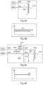
- FIG 3A shows a schematic representation of a test arrangement of a wind turbine according to a first embodiment.
- a wind turbine 100 is shown, which is coupled to a transformer unit 300 via a test unit 400 .
- the wind turbine 100 can, as in 1 be configured as described.
- the testing device 400 is also coupled to the electrical power supply network 200 .
- the transformer unit 300 according to the first embodiment corresponds to the transformer unit according to FIG Figure 2A and has a first and second terminal 301, 302, a (auto)transformer 310 and a medium-voltage switching unit 320.
- the test device 400 has a first connection 401 for coupling to the wind turbine 100, a second connection 402 for coupling to the electrical energy supply network 200, a third connection 403 for coupling to the first connection 301 of the transformer unit and a fourth connection 404 for coupling to the second Connection 302 of the transformer unit 300 on.
- the testing device 400 also has a switch 410 between the first and second connection 401 , 402 and a coil 420 between the first and third connection 401 , 403 and between the switch 410 and the third connection 403 of the testing device 400 .
- the switch 410 of the testing device is closed and the switch 320 of the transformer unit is open, so that the mains voltage U2 is present at the second connection 320 of the transformer unit 300 .
- grid voltage U2 corresponds to voltage U1 at the wind energy installation.
- the first exemplary embodiment thus corresponds to normal operation.
- FIG 4A shows a schematic representation of a test arrangement of a wind turbine according to a second embodiment.
- the structure of the test arrangement with the wind turbine 100, the network 200, the transformer unit 300 and the test device 400 corresponds to the arrangement according to the first exemplary embodiment of FIG Figure 3A .
- switch 410 is closed and switch 320 is also closed.
- both switches 410, 420 are therefore closed, so that a circulating current is produced which is driven by the voltage difference U3 between U1 and U2.
- This circulating current is limited by the coil 420 and is independent of the current which is made available by the wind energy installation 100 .
- the magnitude of the circulating current depends on the differential voltage U3. For example, if the differential voltage U3 is 10% (of 20 kV), then a coil XSR of 20 ohms results in a circulating current of 60A.
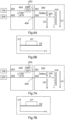
- Figure 5A shows a schematic representation of a test arrangement of a wind turbine according to a third embodiment.
- the test arrangement according to the third exemplary embodiment corresponds to the structure of the test arrangement according to the first or second exemplary embodiment.
- switch 410 is open while switch 320 is closed. Opening the switch 410 results in a voltage increase or voltage drop at the wind energy installation, so that appropriate tests (overvoltage: high voltage ride through HVRT; undervoltage: low voltage ride through LVRT) can be carried out.
- FIG. 6A shows a schematic representation of a test arrangement of a wind turbine according to a fourth exemplary embodiment.
- the structure of the test arrangement according to the fourth exemplary embodiment corresponds to the structure of the test arrangement according to the first, second or third exemplary embodiment.
- the switch 410 is closed, so that the voltage U1 at the wind energy plant corresponds to the voltage U2 of the electrical energy supply network 200 .
- Figure 6B the course of the mains voltage U2 and the course of the voltage U1 at the wind energy installation 100 are shown.
- Figure 7A shows a schematic representation of a test arrangement according to a fifth embodiment.
- the structure of the test arrangement corresponds to the structure of the test arrangement according to the first, second, third or fourth exemplary embodiment.
- the switch 320 is opened so that the test process is ended.
- the switch positions of the switches 410 and 320 according to the fifth exemplary embodiment thus correspond to the switch positions according to the second exemplary embodiment.
- Figure 7B shows the course of the mains voltage U2 and the course of the voltage U1 at the wind turbine.
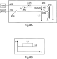
- FIG 8A shows a schematic representation of a test arrangement of a wind turbine according to a sixth exemplary embodiment.
- a test unit 450 is shown, which has an autotransformer 310 , a medium-voltage switching unit 320 , a coil 420 , a switch 410 and a second switch 430 .
- Figure 8B shows the course of the mains voltage U2 and the voltage U1 at the wind turbine.
- the testing device 400 is arranged in a standard container 500 .
- the standard container 500 has a first and second door 510,520.
- the standard container 500 has a medium-voltage area 540 and an area 530 separated therefrom by a wall 541, in which no medium-voltage is present.
- a remote control 531 may be provided in the area 530 to control the operation of the testing apparatus.
- the test device 400 according to one of the exemplary embodiments 1 to 5 can be arranged in the medium-voltage area 540 .
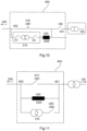
- the test arrangement 405 has an autotransformer 310, a first and second switch S1, S2 (before and after the autotransformer 310), a coil 420, XSR and two switches, in particular circuit breakers.
- the testing unit can be coupled to a wind turbine 100 and the power grid 200 .
- the testing unit 450 can be coupled to a wind energy installation 100 by means of a first connection 401 .
- the testing unit 450 can be coupled to an electrical power supply network 200 via a second connection 402 .
- Between the first and second connection 401, 402 is a first circuit breaker or switch 410 and a further circuit breaker CB are provided.
- the second circuit breaker CB is coupled to the first port.
- An autotransformer 310 with a first and second switch S1 , S2 and a coil 420 is connected in parallel with the protective switch 410 .
- the autotransformer 310 is connected in series with the coil 420 .
- switches S1, S2 are closed and switch 410 is also closed, a circulating current can flow through the transformer and coil. If the two switches S1, S2 are closed and the switch 410 is open, then the circulating current is 0 and an overvoltage test case (high voltage ride through) can be carried out.
- the voltage boost depends on the stage of the transformer.
- FIG. 11 shows a schematic circuit diagram of a test arrangement for a wind turbine.
- the circuit diagram is not the subject of the independent claims.
- the autotransformer 310 and the coil 420 are provided in parallel with a circuit breaker 410 .
- a further circuit breaker 440 is provided in series with the autotransformer 310 .
- the testing arrangement 450 can be coupled to a wind turbine 100 and an electrical power grid 200 .
- circuit breaker 410 In normal operation, circuit breaker 410 is closed and circuit breaker 440 is open. If circuit breaker 410 is opened and circuit breaker 440 is open, wind turbine 100 is operated with coil 420 connected upstream. There is no circulating current. When the circuit breaker 440 is closed, a circulating current flows in the circuit of the autotransformer 310 and coil 420 with a voltage increase/decrease at terminal 401. When the circuit breaker 440 is opened, the WEC is operated again via the coil 420 and the over/under voltage test is complete . When the circuit breaker 410 is closed, the plant is back in normal operation.
Landscapes
- Physics & Mathematics (AREA)
- General Physics & Mathematics (AREA)
- Engineering & Computer Science (AREA)
- Power Engineering (AREA)
- Wind Motors (AREA)
Description
- Die vorliegende Erfindung betrifft eine Verwendung einer Windenergieanlagen-Prüfvorrichtung und ein Prüfverfahren zum Prüfen einer Windenergieanlage.
- Damit eine Windenergieanlage eine entsprechende Zulassung erhält, müssen verschiedene Tests durchgeführt werden, um nachzuweisen, dass die Windenergieanlage allen Anforderungen entspricht. Bei derartigen Tests werden Fehler in einem Energieversorgungsnetzwerk wie beispielsweise eine Unterfrequenz, eine Überfrequenz, eine Über-/Unterspannung, ein Kurzschluss etc. nachgebildet bzw. simuliert und die Reaktion der Windenergieanlage auf einen derartigen Fehler wird erfasst.
-
DE 10 2008 049 629 A1 beschreibt eine Windenergieanlagen-Prüfeinrichtung zum Erzeugen oder Simulieren von Fehlern in einem Energieversorgungsnetz. Dazu ist die Prüfeinrichtung dazu ausgestaltet, Netzfehler definiert zu erzeugen. Die Prüfeinrichtung weist eine Schalteinrichtung zum Zuschalten einer elektrischen Störkomponente in Bezug auf einen Netzparameter auf. Die Prüfeinrichtung weist einen Spartransformator für die elektrische Störkomponente auf. Das ungestörte Netz des Energieversorgungsunternehmens wird an einen Primärwicklungsanschluss angelegt und der Sekundärwicklungsanschluss wird an ein in Bezug auf den Netzparameter gestörtes Netz ausgegeben.WO 2012/113951 A1 beschreibt eine Verwendung einer Prüfvorrichtung zum Erzeugen von Strom und Spannungswerten, die einem Fehler in einem Energieversorgungsnetz entsprechen. Die Prüfvorrichtung weist eine Transformatoreinheit mit einem Transformator und einer Schalteinheit, einen ersten Anschluss zum Anschließen an eine zu prüfende Windenergieanlage, und einen zweiten Anschluss zum Anschließen an das Energieversorgungsnetz und eine Spuleneinheit auf. - Als weiteren Stand der Technik wird auf die folgenden Dokumente verwiesen:
DE 10 2010 060 333 A1 ,DE 20 2012 001 061 U1 ,US 2012 / 0 144 909 A1 undEP 2 146 264 A1 . - Es ist eine Aufgabe der Erfindung, eine Windenergieanlagen-Prüfvorrichtung vorzusehen, welche eine verbesserte Prüfung einer Windenergieanlage ermöglicht.
- Diese Aufgabe wird durch eine Windenergieanlagen-Prüfvorrichtung gemäß Anspruch 1 und durch ein Prüfverfahren nach Anspruch 4 gelöst.
- Somit wird eine Verwendung einer Windenergieanlagen-Prüfvorrichtung zum Erzeugen von Strom- und/oder Spannungswerten, die einem Fehler in einem Energieversorgungsnetz entsprechen, vorgesehen. Die Prüfvorrichtung weist eine Transformatoreinheit mit einem Spartransformator und einer Transformator-Schalteinheit, einen ersten Anschluss zum Anschließen an eine zu prüfende Windenergieanlage, einen zweiten Anschluss zum Anschließen an ein Energieversorgungsnetz, eine Spuleneinheit in Reihe zu dem ersten Anschluss und eine Prüfschalteinheit zwischen dem ersten und zweiten Anschluss auf. Die Spuleneinheit ist in Reihe zu dem Spartransformator geschaltet. In einer ersten Betriebsart, nämlich der Normalbetriebsart, wird die Transformator-Schalteinheit geöffnet und die Prüfschalteinheit geschlossen. In einer zweiten Betriebsart, nämlich der Prüfbetriebsart, wird zuerst die Transformator-Schalteinheit geschlossen, so dass ein Kreisstrom fließen kann und die Prüfschalteinheit wird danach geöffnet, so dass kein Kreisstrom mehr fließt und eine Spannungserhöhung an dem ersten Anschluss anliegt.
- Die Erfindung betrifft ebenfalls ein Prüfverfahren zum Prüfen einer Windenergieanlage durch Erzeugen von Strom und/oder Spannungswerten, die einen Fehler in einem Energieversorgungsnetz entsprechen, mittels einer Prüfvorrichtung, welche eine Transformatoreinheit mit einem Spartransformator und einer Transformator-Schalteinheit, einen ersten Anschluss zum Anschließen an eine zu prüfende Windenergieanlage, einen zweiten Anschuss zum Anschließen an ein Energieversorgungsnetz, eine Spuleneinheit in Reihe zu dem ersten Anschluss und eine Prüfschalteinheit zwischen dem ersten und zweiten Anschluss aufweist. Die Spuleneinheit ist in Reihe zu dem Spartransformator geschaltet. In einer ersten Betriebsart, nämlich der Normalbetriebsart, wird die Transformator-Schalteinheit geöffnet und die Prüfschalteinheit wird geschlossen. In einer zweiten Betriebsart, nämlich der Prüfbetriebsart, wird die Transformator-Schalteinheit geschlossen, so dass ein Kreisstrom fließen kann. Anschließend kann die Prüfschalteinheit geöffnet werden, so dass kein Kreisstrom mehr fließt und eine Spannungserhöhung an dem ersten Anschluss anliegt.
- Gemäß einem nicht beanspruchten Beispiel ist eine Windenergieanlagen-Prüfvorrichtung zum Erzeugen von Strom und/oder Spannungswerten vorgesehen, die einen Fehler in einem Energieversorgungsnetz entsprechen. Die Prüfvorrichtung weist einen Transformator und zwei Transformator-Schalteinheiten auf, welche vor und hinter dem Transformator angeordnet sind. Die Prüfvorrichtung weist einen ersten Anschluss zum Anschließen an eine zu prüfende Windenergieanlage und einen zweiten Anschluss zum Anschließen an ein Energieversorgungsnetz auf. Die Prüfeinheit weist ferner eine Spuleneinheit in Reihe mit dem Transformator und eine Prüfschalteinheit zwischen dem ersten und zweiten Anschluss auf. Die Prüfschalteinheit ist parallel zu der Reihenschaltung aus dem Transformator und der Spuleneinheit angeordnet. In einer ersten Betriebsart, nämlich der normalen Betriebsart sind die zwei Transformator-Schalteinheiten geschlossen und die Prüfschalteinheit ist ebenfalls geschlossen. In einer zweiten Betriebsart, nämlich der Prüfbetriebsart, sind die zwei Transformator-Schalteinheiten zuerst geschlossen, so dass ein Kreisstrom fließt und die Prüfschalteinheit danach geöffnet wird, so dass kein Kreisstrom mehr fließt und eine Spannungserhöhung oder Spannungsabsenkung an dem ersten Anschluss anliegt.
- Gemäß einem nicht beanspruchten Beispiel ist eine Windenergieanlage-Prüfvorrichtung zum Erzeugen von Strom und/oder Spannungswerten vorgesehen, die einem Fehler in einem Energieversorgungsnetz entsprechen. Die Prüfvorrichtung weist einen Transformator und eine Transformator-Schalteinheit in Reihe zum Transformator, einen ersten Anschluss zum Anschließen an eine zu prüfende Windenergieanlage, einen zweiten Anschluss zum Anschließen an ein Energieversorgungsnetz, eine Spuleneinheit parallel zu der Reihenschaltung aus Transformator und Transformator-Schalteinheit und eine Prüfschalteinheit zwischen dem ersten und zweiten Anschluss auf. In einer ersten Betriebsart, nämlich der Normalbetriebsart, ist die Transformator-Schalteinheit geöffnet und die Prüfschalteinheit ist geschlossen. In einer zweiten Betriebsart, nämlich der Prüfbetriebsart, ist die Prüfschalteinheit zuerst geöffnet und die Transformator-Schalteinheit ist geschlossen, so dass eine Spannungserhöhung oder Spannungsabsenkung an dem ersten Anschluss anliegt, wobei die Spannungserhöhung oder Spannungsabsenkung beendet wird, wenn die Transformator-Schalteinheit geschlossen wird.
- Gemäß einem Aspekt der vorliegenden Erfindung weist die Prüfvorrichtung ein Gehäuse in Form eines Standardcontainers auf.
- Gemäß einem weiteren Aspekt der vorliegenden Erfindung ist eine weitere Prüfschalteinheit vorgesehen, welche zwischen dem zweiten Anschluss und der ersten Prüfschalteinheit vorgesehen ist.
- Weitere Ausgestaltungen der Erfindung sind Gegenstand der Unteransprüche.
- Vorteile und Ausführungsbeispiele der Erfindung werden nachstehend anhand der Zeichnungen näher erläutert.
- Fig. 1
- zeigt eine schematische Darstellung einer Windenergieanlage gemäß der Erfindung,
- Fig. 2A
- zeigt eine schematische Darstellung einer Prüfanordnung einer Windenergieanlage,
- Fig. 2B
- zeigt einen Graphen zur Veranschaulichung der Spannung an einer Windenergieanlage sowie einer Netzspannung,
- Fig. 3A
- zeigt eine schematische Darstellung einer Prüfanordnung einer Windenergieanlage gemäß einem ersten Ausführungsbeispiel,
- Fig. 3B
- zeigt einen Graphen zur Veranschaulichung der Netzspannung bei einer Prüfanordnung gemäß dem ersten Ausführungsbeispiel,
- Fig. 4A
- zeigt eine schematische Darstellung einer Prüfanordnung einer Windenergieanlage gemäß einem zweiten Ausführungsbeispiel,
- Fig. 4B
- zeigt einen Graphen zur Veranschaulichung der Netzspannung bei einer Prüfanordnung gemäß dem zweiten Ausführungsbeispiel,
- Fig. 5A
- zeigt eine schematische Darstellung einer Prüfanordnung einer Windenergieanlage gemäß einem dritten Ausführungsbeispiel,
- Fig. 5B
- zeigt einen Graphen zur Veranschaulichung der Netzspannung bei einer Prüfanordnung gemäß dem dritten Ausführungsbeispiel,
- Fig. 6A
- zeigt eine schematische Darstellung einer Prüfanordnung einer Windenergieanlage gemäß einem vierten Ausführungsbeispiel,
- Fig. 6B
- zeigt einen Graphen zur Veranschaulichung des Spannungsverlaufs bei der Prüfanordnung gemäß dem vierten Ausführungsbeispiel,
- Fig. 7A
- zeigt eine schematische Darstellung einer Prüfanordnung gemäß einem fünften Ausführungsbeispiel,
- Fig. 7B
- zeigt einen Graphen zur Veranschaulichung des Spannungsverlaufs bei der Prüfanordnung gemäß dem fünften Ausführungsbeispiel,
- Fig. 8A
- zeigt eine schematische Darstellung zur Veranschaulichung einer Prüfanordnung einer Windenergieanlage gemäß einem sechsten Ausführungsbeispiel,
- Fig. 8B
- zeigt einen Graphen zur Veranschaulichung eines Spannungsverlaufs bei einer Prüfanordnung gemäß einem sechsten Ausführungsbeispiel,
- Fig. 9
- zeigt eine schematische Schnittansicht einer Prüfvorrichtung gemäß einem siebten Ausführungsbeispiel,
- Fig. 10
- zeigt ein schematisches Blockschaltbild einer Prüfanordnung einer Windenergieanlage gemäß einem achten Ausführungsbeispiel, und
- Fig. 11
- zeigt ein schematisches Schaltbild einer Prüfanordnung für eine Windenergieanlage.
-
Fig. 1 zeigt eine schematische Darstellung einer Windenergieanlage gemäß der Erfindung. Die Windenergieanlage 100 weist einen Turm 102 und eine Gondel 104 auf dem Turm 102 auf. An der Gondel 104 ist ein aerodynamischer Rotor 106 mit drei Rotorblättern 108 und einem Spinner 110 vorgesehen. Der aerodynamische Rotor 106 wird im Betrieb der Windenergieanlage durch den Wind in eine Drehbewegung versetzt und dreht somit auch einen Rotor oder Läufer eines Generators, welcher direkt oder indirekt mit dem aerodynamischen Rotor 106 gekoppelt ist. Der elektrische Generator ist in der Gondel 104 angeordnet und erzeugt elektrische Energie. Die Pitchwinkel der Rotorblätter 108 können durch Pitchmotoren an den Rotorblattwurzeln 108b der jeweiligen Rotorblätter 108 verändert werden. -
Fig. 2A zeigt eine schematische Darstellung einer Prüfanordnung einer Windenergieanlage. Die Windenergieanlage 100 ist über eine Transformatoreinheit 300 mit einem elektrischen Energieversorgungsnetz 200 gekoppelt. Die Transformatoreinheit 300 weist einen ersten Anschluss 301 und einen zweiten Anschluss 302 auf. Die Windenergieanlage 300 ist an den ersten Anschluss 301 und das elektrische Energieversorgungsnetz 200 ist an den zweiten Anschluss 302 angeschlossen bzw. gekoppelt. Die Transformatoreinheit 300 weist ferner einen (Spar)transformator 310 sowie eine Mittelspannungsschalteinheit 320 auf. Diese Mittelspannungsschalteinheit 320 ist über den zweiten Anschluss 302 mit dem elektrischen Energieversorgungsnetz 200 gekoppelt. Ein Spartransformator ist ein Transformator ohne galvanische Trennung. - Der (Spar)transformator 310 sollte mindestens auf die Nennleistung der Windenergieanlage ausgelegt werden. Der maximale Strom ergibt sich aus der Nennscheinleistung des Transformators bei der kleinsten Spannung beim Unterspannung-Betrieb LVRT (Low Voltage Ride Through). Der Transformator ist (hermetisch) gekapselt und z. B. Öl-gekühlt. Der Transformator weist mehrere Stufen auf. Anzapfungen sind bei Überspannungsbetrieb HVRT (High Voltage Ride Through) bei +5; +10; +15; +25; +30 und beim Unterspannungsbetrieb LVRT bei -3,9; -7,7; -11,6; -15,4; -19,3; -23,1 möglich.
- Der Spartransformator kann in einem Standardcontainer, beispielsweise ein 20 oder 40-Fuß Seecontainer, vorgesehen sein.
- Mittels der Transformatoreinheit 300 kann eine dauerhafte Spannungserhöhung oder Spannungsabsenkung an der Windenergieanlage 100 simuliert werden bzw. eine dauerhafte Spannungserhöhung oder Spannungsabsenkung kann der Windenergieanlage 100 zu Testzwecken zugeführt werden, um herauszufinden, wie sich die Windenergieanlage in einem Netzfehlerfall verhält.
-
Fig. 2B zeigt einen Graphen zur Veranschaulichung des Spannungsverlaufs an der Windenergieanlage U1 und die Spannung U2 des elektrischen Energieversorgungsnetzes. -
Fig. 3A zeigt eine schematische Darstellung einer Prüfanordnung einer Windenergieanlage gemäß einem ersten Ausführungsbeispiel. InFig. 3A ist eine Windenergieanlage 100 gezeigt, welche über eine Prüfeinheit 400 mit einer Transformatoreinheit 300 gekoppelt ist. Die Windenergieanlage 100 kann wie inFig. 1 beschrieben ausgestaltet sein. Die Prüfvorrichtung 400 ist ebenfalls mit dem elektrischen Energieversorgungsnetz 200 gekoppelt. Die Transformatoreinheit 300 gemäß dem ersten Ausführungsbeispiel entspricht der Transformatoreinheit gemäßFig. 2A und weist einen ersten und zweiten Anschluss 301, 302, einen (Spar)transformator 310 sowie eine Mittelspannungsschalteinheit 320 auf. - Die Prüfvorrichtung 400 weist einen ersten Anschluss 401 zur Kopplung mit der Windenergieanlage 100, einen zweiten Anschluss 402 zur Kopplung mit dem elektrischen Energieversorgungsnetz 200, einen dritten Anschluss 403 zur Kopplung mit dem ersten Anschluss 301 der Transformatoreinheit und einen vierten Anschluss 404 zum Koppeln mit dem zweiten Anschluss 302 der Transformatoreinheit 300 auf.
- Die Prüfvorrichtung 400 weist ferner einen Schalter 410 zwischen dem ersten und zweiten Anschluss 401, 402 sowie eine Spule 420 zwischen dem ersten und dritten Anschluss 401, 403 sowie zwischen dem Schalter 410 und dem dritten Anschluss 403 der Prüfvorrichtung 400 auf. In
Fig. 3A ist der Schalter 410 der Prüfvorrichtung geschlossen und der Schalter 320 der Transformatoreinheit ist offen, so dass die Netzspannung U2 an dem zweiten Anschluss 320 der Transformatoreinheit 300 anliegt. - In
Fig. 3B ist die Netzspannung U2 gezeigt. - Gemäß dem ersten Ausführungsbeispiel (Schalter 410 geschlossen, Schalter 320 offen) entspricht die Netzspannung U2 der Spannung U1 an der Windenergieanlage. Somit entspricht das erste Ausführungsbeispiel einem Normalbetrieb.
-
Fig. 4A zeigt eine schematische Darstellung einer Prüfanordnung einer Windenergieanlage gemäß einem zweiten Ausführungsbeispiel. Der Aufbau der Prüfanordnung mit der Windenergieanlage 100, dem Netz 200, der Transformatoreinheit 300 sowie der Prüfvorrichtung 400 entspricht der Anordnung gemäß dem ersten Ausführungsbeispiel vonFig. 3A . Gemäß dem zweiten Ausführungsbeispiel ist der Schalter 410 geschlossen und der Schalter 320 ist ebenfalls geschlossen. Gemäß dem zweiten Ausführungsbeispiel sind somit beide Schalter 410, 420 geschlossen, so dass ein Kreisstrom entsteht, welcher durch die Spannungsdifferenz U3 zwischen U1 und U2 angetrieben wird. Dieser Kreisstrom wird durch die Spule 420 begrenzt und zwar unabhängig von dem Strom, welcher durch die Windenergieanlage 100 zur Verfügung gestellt wird. - Die Höhe des Kreisstromes ist abhängig von der Differenzspannung U3. Wenn die Differenzspannung U3 beispielsweise 10% beträgt (von 20 kV), dann ergibt sich bei einer Spule XSR von 20 Ohm ein Kreisstrom von 60A.
- In
Fig. 4B ist wiederum die Spannung U2 des elektrischen Energieversorgungsnetzes dargestellt. -
Fig. 5A zeigt eine schematische Darstellung einer Prüfanordnung einer Windenergieanlage gemäß einem dritten Ausführungsbeispiel. Hierbei entspricht die Prüfanordnung gemäß dem dritten Ausführungsbeispiel dem Aufbau der Prüfanordnung gemäß dem ersten oder zweiten Ausführungsbeispiel. Gemäß dem dritten Ausführungsbeispiel ist der Schalter 410 geöffnet, während der Schalter 320 geschlossen ist. Durch Öffnen des Schalters 410 kommt es zu einer Spannungserhöhung oder Spannungsabsenkung an der Windenergieanlage, so dass entsprechende Tests (Überspannung: High voltage ride through HVRT; Unterspannung: Low voltage ride through LVRT) durchgeführt werden können. - In
Fig. 5B ist eine Spannungserhöhung der Spannung U1 an der Windenergieanlage in Abhängigkeit der Betriebsposition des Schalters 410 dargestellt. -
Fig. 6A zeigt eine schematische Darstellung einer Prüfanordnung einer Windenergieanlage gemäß einem vierten Ausführungsbeispiel. Der Aufbau der Prüfanordnung gemäß dem vierten Ausführungsbeispiel entspricht dem Aufbau der Prüfanordnung gemäß dem ersten, zweiten oder dritten Ausführungsbeispiel. Gemäß dem vierten Ausführungsbeispiel wird der Schalter 410 geschlossen, so dass die Spannung U1 an der Windenergieanlage der Spannung U2 des elektrischen Energieversorgungsnetzes 200 entspricht. InFig. 6B ist der Verlauf der Netzspannung U2 sowie der Verlauf der Spannung U1 an der Windenergieanlage 100 dargestellt. -
Fig. 7A zeigt eine schematische Darstellung einer Prüfanordnung gemäß einem fünften Ausführungsbeispiel. Der Aufbau der Prüfanordnung entspricht dem Aufbau der Prüfanordnung gemäß dem ersten, zweiten, dritten oder vierten Ausführungsbeispiel. Gemäß dem fünften Ausführungsbeispiel wird der Schalter 320 geöffnet, so dass der Prüfvorgang beendet ist. Damit entsprechen die Schalterpositionen der Schalter 410 und 320 gemäß dem fünften Ausführungsbeispiel den Schalterpositionen gemäß dem zweiten Ausführungsbeispiel. - In
Fig. 7B ist der Verlauf der Netzspannung U2 sowie der Verlauf der Spannung U1 an der Windenergieanlage dargestellt. -
Fig. 8A zeigt eine schematische Darstellung einer Prüfanordnung einer Windenergieanlage gemäß einem sechsten Ausführungsbeispiel. Gemäß dem sechsten Ausführungsbeispiel ist eine Prüfeinheit 450 gezeigt, welche einen Spartransformator 310, eine Mittelspannungsschalteinheit 320, eine Spule 420, einen Schalter 410 sowie einen zweiten Schalter 430 aufweist. - In
Fig. 8B ist der Verlauf der Netzspannung U2 sowie der Spannung U1 an der Windenergieanlage dargestellt. -
Fig. 9 zeigt einen schematischen Querschnitt einer Prüfvorrichtung gemäß einem siebten Ausführungsbeispiel. Die Prüfvorrichtung 400 ist in einem Standardcontainer 500 angeordnet. Der Standardcontainer 500 weist eine erste und zweite Tür 510, 520 auf. Ferner weist der Standardcontainer 500 einen Mittelspannungsbereich 540 sowie einen davon durch eine Wand 541 getrennten Bereich 530 auf, in welchem keine Mittelspannung vorhanden ist. In dem Bereich 530 kann eine Fernbedienung 531 vorgesehen sein, um den Betrieb der Prüfvorrichtung zu steuern. Die Prüfvorrichtung 400 gemäß einem der Ausführungsbeispiele 1 bis 5 kann in dem Mittelspannungsbereich 540 angeordnet sein. -
Fig. 10 zeigt ein schematisches Blockschaltbild einer Prüfanordnung einer Windenergieanlage gemäß einem achten Ausführungsbeispiel. Die Prüfanordnung 405 weist einen Spartransformator 310, einen ersten und zweiten Schalter S1, S2 (vor und hinter dem Spartransformator 310), eine Spule 420, XSR sowie zwei Schalter, insbesondere Schutzschalter, auf. Die Prüfeinheit kann mit einer Windenergieanlage 100 und dem Energieversorgungsnetz 200 gekoppelt werden. Insbesondere ist die Prüfeinheit 450 mittels eines ersten Anschlusses 401 mit einer Windenergieanlage 100 koppelbar. Ferner ist die Prüfeinheit 450 über einen zweiten Anschluss 402 mit einem elektrischen Energieversorgungsnetz 200 koppelbar. Zwischen dem ersten und zweiten Anschluss 401, 402 ist ein erster Schutzschalter bzw. Schalter 410 sowie ein weiterer Schutzschalter CB vorgesehen. Der zweite Schutzschalter CB ist mit dem ersten Anschluss gekoppelt. - Parallel zu dem Schutzschalter 410 ist ein Spartransformator 310 mit einem ersten und zweiten Schalter S1, S2 und einer Spule 420 geschaltet.
- Gemäß dem achten Ausführungsbeispiel ist der Spartransformator 310 in Reihe mit der Spule 420 geschaltet. Wenn die Schalter S1, S2 geschlossen sind und der Schalter 410 ebenfalls geschlossen ist, dann kann ein Kreisstrom durch den Transformator und die Spule fließen. Wenn die beiden Schalter S1, S2 geschlossen sind und der Schalter 410 geöffnet ist, dann ist der Kreisstrom 0 und ein Überspannungstestfall (High Voltage Ride Through) kann durchgeführt werden. Die Spannungsanhebung ist hierbei abhängig von der Stufe des Transformators.
- Wenn anschließend beide Schalter S1, S2 geschlossen sind und der Schalter 410 ebenfalls geschlossen ist, dann kann wieder ein Kreisstrom fließen.
-
Fig. 11 zeigt ein schematisches Schaltbild einer Prüfanordnung für eine Windenergieanlage. Das Schaltbild ist nicht Gegenstand der unabhängigen Ansprüche. Der Spartransformator 310 und die Spule 420 sind parallel zu einem Schutzschalter 410 vorgesehen. In Reihe zu dem Spartransformator 310 ist ein weiterer Schutzschalter 440 vorgesehen. Die Prüfungsanordnung 450 kann mit einer Windenergieanlage 100 und einem elektrischen Energieversorgungsnetz 200 gekoppelt werden. - Der Versuchsablauf wird nachfolgend erläutert:
Im Normalbetrieb ist der Schutzschalter 410 geschlossen und der Schutzschalter 440 ist offen. Wenn der Schutzschalter 410 geöffnet wird und Schutzschalter 440 offen ist, wird die Windenergieanlage 100 mit der vorgeschalteten Spule 420 betrieben. Es fließt kein Kreisstrom. Wenn der Schutzschalter 440 geschlossen wird, fließt ein Kreisstrom in Stromkreis Spartrafo 310 und Spule 420 mit einer Spannungsanhebung / Absenkung am Anschluss 401. Wenn der Schutzschalter 440 geöffnet wird, wird die WEA wieder über die Spule 420 betrieben und die Über- / Unterspannungsprüfung ist beendet. Wenn der Schutzschalter 410 geschlossen wird, ist die Anlage wieder im Normalbetrieb. - In den
Figuren 4A, 5A ,6A, 7A und8A ist jeweils eine Reihenschaltung aus der Spule 240 und dem Spartransformator 310 vorhanden. Dies hat zur Folge, dass eine Spannung über der Spule 420 abfallen kann. Insbesondere wenn mehrere Windenergieanlagen geprüft werden, kann dieser Spannungsabfall über der Spule 420 zu berücksichtigen sein. Die Prüfungsanordnung gemäßFig. 11 stellt eine Parallelschaltung der Spule 420 sowie des Spartransformators 310 dar. Durch diese Parallelschaltung kann ein Spannungsabfall über der Spule 420 vermieden werden.
Claims (4)
- Verwendung einer Windenergieanlagen-Prüfvorrichtung (400) zum Erzeugen von Strom- und/oder Spannungswerten, die einem Fehler in einem Energieversorgungsnetz (200) entsprechen, wobei die Windenergieanlagen-Prüfvorrichtung eine Transformatoreinheit (200) mit einem Spartransformator (310) und einer Transformator-Schalteinheit (320), einen ersten Anschluss (401) zum Anschließen an eine zu prüfende Windenergieanlage (100), einen zweiten Anschluss (402) zum Anschließen an ein Energieversorgungsnetz (200), eine Spuleneinheit (420) in Reihe zu dem ersten Anschluss (401), und eine Prüfschalteinheit (410) zwischen dem ersten und zweiten Anschluss (401, 402) aufweist,wobei die Spuleneinheit (420) in Reihe zu dem Spartransformator (310) geschaltet ist,wobei in einer ersten Betriebsart, nämlich der Normalbetriebsart, die Transformator-Schalteinheit (320) geöffnet ist und die Prüfschalteinheit (410) geschlossen ist,wobei in einer zweiten Betriebsart, nämlich der Prüfbetriebsart, die Transformator-Schalteinheit (320) zuerst geschlossen wird, so dass ein Kreisstrom fließt und die Prüfschalteinheit (410) danach geöffnet wird, so dass kein Kreisstrom mehr fließt und eine Spanungserhöhung an dem ersten Anschluss (401) anliegt.
- Verwendung einer Windenergieanlagen-Prüfvorrichtung (400) nach Anspruch 1, wobei die Windenergieanlagen-Prüfvorrichtung ein Gehäuse (500) in Form eines StandardContainers aufweist.
- Verwendung einer Windenergieanlagen-Prüfvorrichtung (400) nach einem der Ansprüche 1 bis 2, wobei die Windenergieanlagen-Prüfvorrichtung eine zweite Prüfschalteinheit (430) zwischen dem zweiten Anschluss (402) und der ersten Prüfschalteinheit (410) aufweist.
- Prüfverfahren zum Prüfen einer Windenergieanlage durch Erzeugen von Strom- und/oder Spannungswerten, die einem Fehler in einem Energieversorgungsnetz (200) entsprechen, mittels einer Prüfvorrichtung (400), welche eine Transformatoreinheit (200) mit einem Spartransformator (310) und einer Transformator-Schalteinheit (320), einen ersten Anschluss (401) zum Anschließen an eine zu prüfende Windenergieanlage (100), einen zweiten Anschluss (402) zum Anschließen an ein Energieversorgungsnetz (200), eine Spuleneinheit (420) in Reihe zu dem ersten Anschluss (401) und eine Prüfschalteinheit (410) zwischen dem ersten und zweiten Anschluss (401, 402) aufweist, wobei die Spuleneinheit (420) in Reihe zu dem Spartransformator (310) geschaltet ist, mit den Schritten:in einer ersten Betriebsart, nämlich der Normalbetriebsart, Öffnen der Transformatorschalteinheit (320) und Schließen der Prüfschalteinheit (410), undin einer zweiten Betriebsart, nämlich der Prüfbetriebsart, Schließen der Transformator-Schalteinheit (320), so dass ein Kreisstrom fließt, undanschließendes Öffnen der Prüfschalteinheit (410), so dass kein Kreisstrom mehr fließt und eine Spannungserhöhung an dem ersten Anschluss (401) anliegt.
Applications Claiming Priority (2)
| Application Number | Priority Date | Filing Date | Title |
|---|---|---|---|
| DE102015201857.1A DE102015201857A1 (de) | 2015-02-03 | 2015-02-03 | Windenergieanlagen-Prüfvorrichtung und Verfahren zum Prüfen einer Windenergieanlage |
| DE102015114126.4A DE102015114126A1 (de) | 2015-08-26 | 2015-08-26 | Windenergieanlagen-Prüfvorrichtung und Verfahren zum Prüfen einer Windenergieanlage |
Publications (3)
| Publication Number | Publication Date |
|---|---|
| EP3056916A1 EP3056916A1 (de) | 2016-08-17 |
| EP3056916B1 EP3056916B1 (de) | 2020-05-06 |
| EP3056916B2 true EP3056916B2 (de) | 2023-03-15 |
Family
ID=55273161
Family Applications (1)
| Application Number | Title | Priority Date | Filing Date |
|---|---|---|---|
| EP16153567.9A Active EP3056916B2 (de) | 2015-02-03 | 2016-02-01 | Verwendung einer windenergieanlagen-prüfvorrichtung und verfahren zum prüfen einer windenergieanlage |
Country Status (3)
| Country | Link |
|---|---|
| EP (1) | EP3056916B2 (de) |
| DK (1) | DK3056916T4 (de) |
| ES (1) | ES2797100T3 (de) |
Families Citing this family (1)
| Publication number | Priority date | Publication date | Assignee | Title |
|---|---|---|---|---|
| US10996275B2 (en) | 2019-03-19 | 2021-05-04 | Saudi Arabian Oil Company | Low voltage ride-through test apparatus and method of using same |
Family Cites Families (7)
| Publication number | Priority date | Publication date | Assignee | Title |
|---|---|---|---|---|
| ES2264882B1 (es) * | 2005-04-08 | 2008-01-01 | GAMESA INNOVATION & TECHNOLOGY, S.L. | Dispositivo generador de huecos de tension en baja tension. |
| ES2308918B1 (es) | 2007-04-11 | 2009-10-23 | Fundacion Circe-Centro De Investigacion De Recurso Y Consumos Energeticos | Equipo generador de huecos de tension. |
| DE102008049629A1 (de) | 2008-09-30 | 2010-04-08 | Repower Systems Ag | Windenergieanlagenprüfeinrichtung |
| US8514996B2 (en) | 2010-07-14 | 2013-08-20 | Honeywell International Inc. | Real time distributed embedded oscillator operating frequency monitoring |
| DE102010060333B4 (de) | 2010-11-03 | 2013-05-29 | Forschungsgemeinschaft für Elektrische Anlagen und Stromwirtschaft e.V. | Dezentrale Erzeugungsanlage, insbesondere Windenergieanlage, Prüfschaltung sowie Prüfverfahren |
| ES2395364B1 (es) | 2011-02-24 | 2013-12-27 | For Optimal Renewable Energy Systems, S.L | Equipo generador de perturbaciones eléctricas |
| DE202012001061U1 (de) | 2012-02-02 | 2012-03-08 | Siemens Ag | Testeinrichtung zum Erzeugen einer Überspannung |
-
2016
- 2016-02-01 ES ES16153567T patent/ES2797100T3/es active Active
- 2016-02-01 EP EP16153567.9A patent/EP3056916B2/de active Active
- 2016-02-01 DK DK16153567.9T patent/DK3056916T4/da active
Non-Patent Citations (4)
| Title |
|---|
| ANONYMOUS: "Industrial Power Corruptor - User's Manual IPC-480V-200A, IPC-480V-100A, IPC-480V-50A, IPC-240V-25A", 1 June 2003 (2003-06-01), pages 1 - 59, XP055843631 † |
| BAGGU, M.M.: "Advanced control techniques for doubly fed induction generator-based wind turbine converters to improve low voltage ride-through during system imbalances, doctoral dissertation", THESIS, 2009, XP055778155 † |
| KLOSSE, R.: "High-Voltage-Ride-Through Test System Based on Trans- former Switching", THE 12TH INTERNATIONAL WORKSHOP ON LARGE-SCALE INTEGRATION OF WIND POWER INTO POWER SYSTEMS AS WELL AS ON TRANSMISSION NETWORKS FOR OFFSHORE WIND POWER PLANTS, 2013, London, England, XP055778656 † |
| YONGCHENG ET AL: "Benchmarking of Voltage Sag Generators", THE 38TH ANNUAL CON- FERENCE OF THE IEEE INDUSTRIAL ELECTRONICS SOCIETY, 2012, XP032281485 † |
Also Published As
| Publication number | Publication date |
|---|---|
| EP3056916B1 (de) | 2020-05-06 |
| DK3056916T4 (da) | 2023-05-01 |
| ES2797100T3 (es) | 2020-12-01 |
| DK3056916T3 (da) | 2020-06-29 |
| EP3056916A1 (de) | 2016-08-17 |
Similar Documents
| Publication | Publication Date | Title |
|---|---|---|
| EP2263306B1 (de) | Verfahren zum betreiben einer windenergieanlage mit einer doppelt gespeisten asynchronmaschine sowie windenergieanlage mit einer doppelt gespeisten asynchronmaschine | |
| EP2332229B1 (de) | Windenergieanlagenprüfeinrichtung | |
| EP2244373B1 (de) | Verfahren und elektrische Schaltung zum Testen eines an ein elektrisches Energieversorgungsnetz anschliessbaren Energieerzeugers oder Energieverbrauchers | |
| WO2014033073A1 (de) | Windpark mit gleichspannungsnetz | |
| EP1752659A2 (de) | Verfahren zum Betrieb eines Windenergieanlagenparks sowie Windenergieanlagenpark | |
| EP3033816B1 (de) | Verfahren zum einspeisen elektrischer leistung in ein versorgungsnetz | |
| EP3850721A1 (de) | Windpark mit einer leistungsflusseinheit sowie eine solche leistungsflusseinheit | |
| EP2461027B1 (de) | Anordnung und Verfahren zum Prüfen eines Stromerzeugungssystems | |
| DE102014202426A1 (de) | Verfahren zur Prüfung einer Trennstelle eines Photovoltaik-Wechselrichters und Photovoltaik-Wechselrichter | |
| EP3056916B2 (de) | Verwendung einer windenergieanlagen-prüfvorrichtung und verfahren zum prüfen einer windenergieanlage | |
| EP1513251A2 (de) | Verfahren und Vorrichtung zum Betrieb einer doppelt gespeisten Drehstrommaschine, insbesondere in einer Windkraftanlage | |
| EP2228519B1 (de) | Physikalische Test-Vorrichtung für ein Inselkraftwerk und Inbetriebsetzung eines Inselkraftwerks | |
| DE102015201857A1 (de) | Windenergieanlagen-Prüfvorrichtung und Verfahren zum Prüfen einer Windenergieanlage | |
| DE202007016800U1 (de) | Windkraftanlage mit Synchronisierungsschalter | |
| DE102015114126A1 (de) | Windenergieanlagen-Prüfvorrichtung und Verfahren zum Prüfen einer Windenergieanlage | |
| DE202023101133U1 (de) | System zur Diagnose von einer Windkraftanlage | |
| EP3984124B1 (de) | Dual purpose converter | |
| EP2442119A2 (de) | Verfahren und elektrische Schaltung zum Testen eines an ein elektrisches Energieversorgungsnetz anschließbaren Energieerzeugers oder Energieverbrauchers | |
| DE202012001061U1 (de) | Testeinrichtung zum Erzeugen einer Überspannung | |
| WO2019002528A9 (de) | Verfahren und vorrichtung zum elektrischen verbinden eines transformators mit einem elektrischen netz | |
| EP2904677B1 (de) | Schaltungsanordnung mit einem wechselrichter | |
| WO2012022374A2 (de) | Verfahren zum konfigurieren eines energieautomatisierungsgerätes einer elektrischen energieautomatisierungsanlage und konfigurationsrechner zum durchführen des verfahrens | |
| EP4430303B1 (de) | Windkraftanlage und verschaltung von windkraftanlagen | |
| DE102009054032B4 (de) | Prüfvorrichtung für Windenergieanlagen-Mehrwicklungstransformatoren | |
| EP4320700A1 (de) | Schaltanordnung und verfahren zum zuschalten einer stromerzeugungsanlage zu einem stromverteilernetz und zum trennen von diesem |
Legal Events
| Date | Code | Title | Description |
|---|---|---|---|
| PUAI | Public reference made under article 153(3) epc to a published international application that has entered the european phase |
Free format text: ORIGINAL CODE: 0009012 |
|
| AK | Designated contracting states |
Kind code of ref document: A1 Designated state(s): AL AT BE BG CH CY CZ DE DK EE ES FI FR GB GR HR HU IE IS IT LI LT LU LV MC MK MT NL NO PL PT RO RS SE SI SK SM TR |
|
| AX | Request for extension of the european patent |
Extension state: BA ME |
|
| STAA | Information on the status of an ep patent application or granted ep patent |
Free format text: STATUS: REQUEST FOR EXAMINATION WAS MADE |
|
| 17P | Request for examination filed |
Effective date: 20170217 |
|
| RBV | Designated contracting states (corrected) |
Designated state(s): AL AT BE BG CH CY CZ DE DK EE ES FI FR GB GR HR HU IE IS IT LI LT LU LV MC MK MT NL NO PL PT RO RS SE SI SK SM TR |
|
| GRAP | Despatch of communication of intention to grant a patent |
Free format text: ORIGINAL CODE: EPIDOSNIGR1 |
|
| STAA | Information on the status of an ep patent application or granted ep patent |
Free format text: STATUS: GRANT OF PATENT IS INTENDED |
|
| RIC1 | Information provided on ipc code assigned before grant |
Ipc: G01R 31/42 20060101ALI20200114BHEP Ipc: G01R 31/34 20200101AFI20200114BHEP Ipc: G01R 31/50 20200101ALI20200114BHEP |
|
| INTG | Intention to grant announced |
Effective date: 20200131 |
|
| GRAS | Grant fee paid |
Free format text: ORIGINAL CODE: EPIDOSNIGR3 |
|
| GRAA | (expected) grant |
Free format text: ORIGINAL CODE: 0009210 |
|
| STAA | Information on the status of an ep patent application or granted ep patent |
Free format text: STATUS: THE PATENT HAS BEEN GRANTED |
|
| AK | Designated contracting states |
Kind code of ref document: B1 Designated state(s): AL AT BE BG CH CY CZ DE DK EE ES FI FR GB GR HR HU IE IS IT LI LT LU LV MC MK MT NL NO PL PT RO RS SE SI SK SM TR |
|
| REG | Reference to a national code |
Ref country code: GB Ref legal event code: FG4D Free format text: NOT ENGLISH |
|
| REG | Reference to a national code |
Ref country code: AT Ref legal event code: REF Ref document number: 1267636 Country of ref document: AT Kind code of ref document: T Effective date: 20200515 Ref country code: CH Ref legal event code: EP |
|
| REG | Reference to a national code |
Ref country code: DE Ref legal event code: R096 Ref document number: 502016009805 Country of ref document: DE |
|
| REG | Reference to a national code |
Ref country code: IE Ref legal event code: FG4D Free format text: LANGUAGE OF EP DOCUMENT: GERMAN |
|
| REG | Reference to a national code |
Ref country code: DK Ref legal event code: T3 Effective date: 20200622 |
|
| REG | Reference to a national code |
Ref country code: NL Ref legal event code: FP |
|
| REG | Reference to a national code |
Ref country code: LT Ref legal event code: MG4D |
|
| PG25 | Lapsed in a contracting state [announced via postgrant information from national office to epo] |
Ref country code: GR Free format text: LAPSE BECAUSE OF FAILURE TO SUBMIT A TRANSLATION OF THE DESCRIPTION OR TO PAY THE FEE WITHIN THE PRESCRIBED TIME-LIMIT Effective date: 20200807 Ref country code: NO Free format text: LAPSE BECAUSE OF FAILURE TO SUBMIT A TRANSLATION OF THE DESCRIPTION OR TO PAY THE FEE WITHIN THE PRESCRIBED TIME-LIMIT Effective date: 20200806 Ref country code: FI Free format text: LAPSE BECAUSE OF FAILURE TO SUBMIT A TRANSLATION OF THE DESCRIPTION OR TO PAY THE FEE WITHIN THE PRESCRIBED TIME-LIMIT Effective date: 20200506 Ref country code: IS Free format text: LAPSE BECAUSE OF FAILURE TO SUBMIT A TRANSLATION OF THE DESCRIPTION OR TO PAY THE FEE WITHIN THE PRESCRIBED TIME-LIMIT Effective date: 20200906 Ref country code: PT Free format text: LAPSE BECAUSE OF FAILURE TO SUBMIT A TRANSLATION OF THE DESCRIPTION OR TO PAY THE FEE WITHIN THE PRESCRIBED TIME-LIMIT Effective date: 20200907 Ref country code: LT Free format text: LAPSE BECAUSE OF FAILURE TO SUBMIT A TRANSLATION OF THE DESCRIPTION OR TO PAY THE FEE WITHIN THE PRESCRIBED TIME-LIMIT Effective date: 20200506 Ref country code: SE Free format text: LAPSE BECAUSE OF FAILURE TO SUBMIT A TRANSLATION OF THE DESCRIPTION OR TO PAY THE FEE WITHIN THE PRESCRIBED TIME-LIMIT Effective date: 20200506 |
|
| PG25 | Lapsed in a contracting state [announced via postgrant information from national office to epo] |
Ref country code: HR Free format text: LAPSE BECAUSE OF FAILURE TO SUBMIT A TRANSLATION OF THE DESCRIPTION OR TO PAY THE FEE WITHIN THE PRESCRIBED TIME-LIMIT Effective date: 20200506 Ref country code: BG Free format text: LAPSE BECAUSE OF FAILURE TO SUBMIT A TRANSLATION OF THE DESCRIPTION OR TO PAY THE FEE WITHIN THE PRESCRIBED TIME-LIMIT Effective date: 20200806 Ref country code: RS Free format text: LAPSE BECAUSE OF FAILURE TO SUBMIT A TRANSLATION OF THE DESCRIPTION OR TO PAY THE FEE WITHIN THE PRESCRIBED TIME-LIMIT Effective date: 20200506 Ref country code: LV Free format text: LAPSE BECAUSE OF FAILURE TO SUBMIT A TRANSLATION OF THE DESCRIPTION OR TO PAY THE FEE WITHIN THE PRESCRIBED TIME-LIMIT Effective date: 20200506 |
|
| REG | Reference to a national code |
Ref country code: ES Ref legal event code: FG2A Ref document number: 2797100 Country of ref document: ES Kind code of ref document: T3 Effective date: 20201201 |
|
| PG25 | Lapsed in a contracting state [announced via postgrant information from national office to epo] |
Ref country code: AL Free format text: LAPSE BECAUSE OF FAILURE TO SUBMIT A TRANSLATION OF THE DESCRIPTION OR TO PAY THE FEE WITHIN THE PRESCRIBED TIME-LIMIT Effective date: 20200506 |
|
| PG25 | Lapsed in a contracting state [announced via postgrant information from national office to epo] |
Ref country code: EE Free format text: LAPSE BECAUSE OF FAILURE TO SUBMIT A TRANSLATION OF THE DESCRIPTION OR TO PAY THE FEE WITHIN THE PRESCRIBED TIME-LIMIT Effective date: 20200506 Ref country code: RO Free format text: LAPSE BECAUSE OF FAILURE TO SUBMIT A TRANSLATION OF THE DESCRIPTION OR TO PAY THE FEE WITHIN THE PRESCRIBED TIME-LIMIT Effective date: 20200506 Ref country code: SM Free format text: LAPSE BECAUSE OF FAILURE TO SUBMIT A TRANSLATION OF THE DESCRIPTION OR TO PAY THE FEE WITHIN THE PRESCRIBED TIME-LIMIT Effective date: 20200506 Ref country code: IT Free format text: LAPSE BECAUSE OF FAILURE TO SUBMIT A TRANSLATION OF THE DESCRIPTION OR TO PAY THE FEE WITHIN THE PRESCRIBED TIME-LIMIT Effective date: 20200506 Ref country code: CZ Free format text: LAPSE BECAUSE OF FAILURE TO SUBMIT A TRANSLATION OF THE DESCRIPTION OR TO PAY THE FEE WITHIN THE PRESCRIBED TIME-LIMIT Effective date: 20200506 |
|
| REG | Reference to a national code |
Ref country code: DE Ref legal event code: R026 Ref document number: 502016009805 Country of ref document: DE |
|
| PLBI | Opposition filed |
Free format text: ORIGINAL CODE: 0009260 |
|
| PLAX | Notice of opposition and request to file observation + time limit sent |
Free format text: ORIGINAL CODE: EPIDOSNOBS2 |
|
| PG25 | Lapsed in a contracting state [announced via postgrant information from national office to epo] |
Ref country code: PL Free format text: LAPSE BECAUSE OF FAILURE TO SUBMIT A TRANSLATION OF THE DESCRIPTION OR TO PAY THE FEE WITHIN THE PRESCRIBED TIME-LIMIT Effective date: 20200506 Ref country code: SK Free format text: LAPSE BECAUSE OF FAILURE TO SUBMIT A TRANSLATION OF THE DESCRIPTION OR TO PAY THE FEE WITHIN THE PRESCRIBED TIME-LIMIT Effective date: 20200506 |
|
| 26 | Opposition filed |
Opponent name: VESTAS WIND SYSTEMS A/S Effective date: 20210208 |
|
| PLAB | Opposition data, opponent's data or that of the opponent's representative modified |
Free format text: ORIGINAL CODE: 0009299OPPO |
|
| R26 | Opposition filed (corrected) |
Opponent name: VESTAS WIND SYSTEMS A/S Effective date: 20210208 |
|
| PG25 | Lapsed in a contracting state [announced via postgrant information from national office to epo] |
Ref country code: SI Free format text: LAPSE BECAUSE OF FAILURE TO SUBMIT A TRANSLATION OF THE DESCRIPTION OR TO PAY THE FEE WITHIN THE PRESCRIBED TIME-LIMIT Effective date: 20200506 |
|
| PGFP | Annual fee paid to national office [announced via postgrant information from national office to epo] |
Ref country code: ES Payment date: 20210323 Year of fee payment: 6 |
|
| PLBP | Opposition withdrawn |
Free format text: ORIGINAL CODE: 0009264 |
|
| PLBB | Reply of patent proprietor to notice(s) of opposition received |
Free format text: ORIGINAL CODE: EPIDOSNOBS3 |
|
| PG25 | Lapsed in a contracting state [announced via postgrant information from national office to epo] |
Ref country code: MC Free format text: LAPSE BECAUSE OF FAILURE TO SUBMIT A TRANSLATION OF THE DESCRIPTION OR TO PAY THE FEE WITHIN THE PRESCRIBED TIME-LIMIT Effective date: 20200506 |
|
| REG | Reference to a national code |
Ref country code: BE Ref legal event code: MM Effective date: 20210228 |
|
| PG25 | Lapsed in a contracting state [announced via postgrant information from national office to epo] |
Ref country code: LU Free format text: LAPSE BECAUSE OF NON-PAYMENT OF DUE FEES Effective date: 20210201 Ref country code: LI Free format text: LAPSE BECAUSE OF NON-PAYMENT OF DUE FEES Effective date: 20210228 Ref country code: CH Free format text: LAPSE BECAUSE OF NON-PAYMENT OF DUE FEES Effective date: 20210228 |
|
| PG25 | Lapsed in a contracting state [announced via postgrant information from national office to epo] |
Ref country code: IE Free format text: LAPSE BECAUSE OF NON-PAYMENT OF DUE FEES Effective date: 20210201 |
|
| REG | Reference to a national code |
Ref country code: AT Ref legal event code: MM01 Ref document number: 1267636 Country of ref document: AT Kind code of ref document: T Effective date: 20210201 |
|
| PG25 | Lapsed in a contracting state [announced via postgrant information from national office to epo] |
Ref country code: AT Free format text: LAPSE BECAUSE OF NON-PAYMENT OF DUE FEES Effective date: 20210201 |
|
| REG | Reference to a national code |
Ref country code: CH Ref legal event code: PK Free format text: BERICHTIGUNGEN |
|
| PG25 | Lapsed in a contracting state [announced via postgrant information from national office to epo] |
Ref country code: BE Free format text: LAPSE BECAUSE OF NON-PAYMENT OF DUE FEES Effective date: 20210228 |
|
| RIC2 | Information provided on ipc code assigned after grant |
Ipc: G01R 31/55 20200101ALI20220705BHEP Ipc: G01R 31/42 20060101ALI20220705BHEP Ipc: G01R 31/34 20200101AFI20220705BHEP |
|
| REG | Reference to a national code |
Ref country code: CH Ref legal event code: PK Free format text: TITEL |
|
| PUAH | Patent maintained in amended form |
Free format text: ORIGINAL CODE: 0009272 |
|
| STAA | Information on the status of an ep patent application or granted ep patent |
Free format text: STATUS: PATENT MAINTAINED AS AMENDED |
|
| 27A | Patent maintained in amended form |
Effective date: 20230315 |
|
| AK | Designated contracting states |
Kind code of ref document: B2 Designated state(s): AL AT BE BG CH CY CZ DE DK EE ES FI FR GB GR HR HU IE IS IT LI LT LU LV MC MK MT NL NO PL PT RO RS SE SI SK SM TR |
|
| REG | Reference to a national code |
Ref country code: DE Ref legal event code: R102 Ref document number: 502016009805 Country of ref document: DE |
|
| REG | Reference to a national code |
Ref country code: NL Ref legal event code: FP |
|
| REG | Reference to a national code |
Ref country code: DK Ref legal event code: T4 Effective date: 20230426 |
|
| PG25 | Lapsed in a contracting state [announced via postgrant information from national office to epo] |
Ref country code: HU Free format text: LAPSE BECAUSE OF FAILURE TO SUBMIT A TRANSLATION OF THE DESCRIPTION OR TO PAY THE FEE WITHIN THE PRESCRIBED TIME-LIMIT; INVALID AB INITIO Effective date: 20160201 |
|
| PG25 | Lapsed in a contracting state [announced via postgrant information from national office to epo] |
Ref country code: CY Free format text: LAPSE BECAUSE OF FAILURE TO SUBMIT A TRANSLATION OF THE DESCRIPTION OR TO PAY THE FEE WITHIN THE PRESCRIBED TIME-LIMIT Effective date: 20200506 |
|
| PG25 | Lapsed in a contracting state [announced via postgrant information from national office to epo] |
Ref country code: ES Free format text: LAPSE BECAUSE OF FAILURE TO SUBMIT A TRANSLATION OF THE DESCRIPTION OR TO PAY THE FEE WITHIN THE PRESCRIBED TIME-LIMIT Effective date: 20230315 |
|
| REG | Reference to a national code |
Ref country code: ES Ref legal event code: FD2A Effective date: 20240401 |
|
| PG25 | Lapsed in a contracting state [announced via postgrant information from national office to epo] |
Ref country code: ES Free format text: LAPSE BECAUSE OF NON-PAYMENT OF DUE FEES Effective date: 20220202 |
|
| PG25 | Lapsed in a contracting state [announced via postgrant information from national office to epo] |
Ref country code: MK Free format text: LAPSE BECAUSE OF FAILURE TO SUBMIT A TRANSLATION OF THE DESCRIPTION OR TO PAY THE FEE WITHIN THE PRESCRIBED TIME-LIMIT Effective date: 20200506 Ref country code: ES Free format text: LAPSE BECAUSE OF NON-PAYMENT OF DUE FEES Effective date: 20220202 |
|
| PG25 | Lapsed in a contracting state [announced via postgrant information from national office to epo] |
Ref country code: TR Free format text: LAPSE BECAUSE OF FAILURE TO SUBMIT A TRANSLATION OF THE DESCRIPTION OR TO PAY THE FEE WITHIN THE PRESCRIBED TIME-LIMIT Effective date: 20200506 |
|
| PG25 | Lapsed in a contracting state [announced via postgrant information from national office to epo] |
Ref country code: MT Free format text: LAPSE BECAUSE OF FAILURE TO SUBMIT A TRANSLATION OF THE DESCRIPTION OR TO PAY THE FEE WITHIN THE PRESCRIBED TIME-LIMIT Effective date: 20200506 |
|
| PGFP | Annual fee paid to national office [announced via postgrant information from national office to epo] |
Ref country code: NL Payment date: 20250220 Year of fee payment: 10 |
|
| PGFP | Annual fee paid to national office [announced via postgrant information from national office to epo] |
Ref country code: DK Payment date: 20250219 Year of fee payment: 10 |
|
| PGFP | Annual fee paid to national office [announced via postgrant information from national office to epo] |
Ref country code: FR Payment date: 20250219 Year of fee payment: 10 |
|
| PGFP | Annual fee paid to national office [announced via postgrant information from national office to epo] |
Ref country code: GB Payment date: 20250220 Year of fee payment: 10 |
|
| PGFP | Annual fee paid to national office [announced via postgrant information from national office to epo] |
Ref country code: DE Payment date: 20260302 Year of fee payment: 11 |