EP3057112B1 - Transformateur à huile - Google Patents
Transformateur à huile Download PDFInfo
- Publication number
- EP3057112B1 EP3057112B1 EP15155155.3A EP15155155A EP3057112B1 EP 3057112 B1 EP3057112 B1 EP 3057112B1 EP 15155155 A EP15155155 A EP 15155155A EP 3057112 B1 EP3057112 B1 EP 3057112B1
- Authority
- EP
- European Patent Office
- Prior art keywords
- oil
- supporting structure
- mechanical supporting
- vessel
- oil transformer
- Prior art date
- Legal status (The legal status is an assumption and is not a legal conclusion. Google has not performed a legal analysis and makes no representation as to the accuracy of the status listed.)
- Active
Links
Images

Classifications
-
- H—ELECTRICITY
- H01—ELECTRIC ELEMENTS
- H01F—MAGNETS; INDUCTANCES; TRANSFORMERS; SELECTION OF MATERIALS FOR THEIR MAGNETIC PROPERTIES
- H01F27/00—Details of transformers or inductances, in general
- H01F27/08—Cooling; Ventilating
- H01F27/10—Liquid cooling
- H01F27/12—Oil cooling
- H01F27/14—Expansion chambers; Oil conservators; Gas cushions; Arrangements for purifying, drying, or filling
-
- H—ELECTRICITY
- H01—ELECTRIC ELEMENTS
- H01F—MAGNETS; INDUCTANCES; TRANSFORMERS; SELECTION OF MATERIALS FOR THEIR MAGNETIC PROPERTIES
- H01F27/00—Details of transformers or inductances, in general
- H01F27/02—Casings
- H01F27/025—Constructional details relating to cooling
Definitions
- the invention is related to an oil transformer according to the preamble of claim 1.
- a transformer of this kind is known from EP 2 169 690 A1 .
- GB 945,688 A shows an expansion vessel placed in a metal casing.
- US 2014/240 901 A1 shows a CSC container comprising a transformer and heat exchangers above the transformer but within this container.
- transformers, reactors and other electrical devices used in HV transmission networks of for example 380kV are typically arranged within an oil filled vessel.
- the oil is on one hand insulation medium and on the other hand cooling medium.
- An expansion vessel is fluidic connected with the oil filled vessel in order to handle the thermal expansion of the oil which arises during operation of the respective HV component, for example an oil transformer.
- the wording "transformer” has also to be seen as synonym for a reactor and the wording "oil” covers also comparable insulation fluids such as Ester.
- cooling means are foreseen for cooling the oil transformer, mainly heat exchangers, in particular an oil air heat exchanger or an oil water heat exchanger, or radiators which might be arranged as a radiator battery.
- An HV oil transformer might have a rated power of several 100MVA, a weight of several 100t, a height of for example 6m and above and a length of 12m and above.
- a rated power of several 100MVA a weight of several 100t
- a height of for example 6m and above a height of for example 6m and above
- a length of 12m and above a challenging task.
- the attached components such as cooling means and expansion vessel are transported separately and assembled together with the main part of the oil transformer on site.
- the attached components are normally individually designed with respect to individual requirements for the respective oil transformer.
- the attached components typically differ in size and shape so that as well their transport as their assembly on site is rather individual and time consuming therewith.
- seismic requirements for example with respect to groundwork and a stable arrangement, have to be fulfilled when assembling the components to be attached on site.
- the objective of the invention is to provide an oil transformer with attached components, which are easier to transport and to easier assemble on site.
- CSC Container Safety Convention wherein the standards related thereto are described for example in ISO 668.
- Basic idea of the invention is to modularize the components to be attached to an oil transformer, for example an expansion vessel or the like. All modules have in common, that they are designed in that way, that they can be transported exactly like a CSC container.
- a module comprises a mechanical supporting structure with outer dimensions like a CSC container and a component of an oil transformer fixedly integrated therein.
- CSC containers are a widely known and standardized transportation medium.
- a CSC container complies with standardized dimensions, for example a standardized length of 6,058m or 12,192m, wherein the height amounts 2,591 m and the width 2,438m.
- a transport by ships, trucks or train to any location in the world is possible without any problem.
- the transportation of the components to be attached to an oil transformer is facilitated therewith compared to the transportation in bulky cases as it is common now.
- a respective component to be attached to an oil transformer is fixedly integrated in the mechanical supporting structure, which is not only of advantage for an easier transportation, moreover an easier installation on site is enabled therewith.
- the mechanical supporting structure enables an easy placing on site on the four lower corner points. Any complex groundwork is as less required as a direct assembly with the vessel of the oil transformer. It is also possible to stack the mechanical supporting structures of several modules easily each on each other. Only respective fluidic connections in between the oil filled transformer vessel and the respective mechanical supporting structure have to be mounted on site.
- the mechanical supporting structure is designed in that way, that it has a comparable life cycle than the oil transformer itself, so that the components fixedly integrated in the mechanical supporting structure can permanently remain therein.
- the mechanical supporting structure of the expansion vessel comprises coupling means at its outer surface which are foreseen as a part of the fluidic connection in between the expansion vessel and the oil filled vessel,
- the first part of the fluidic connection in between the expansion vessel and the coupling means is integrated in the mechanical supporting structure. So the second part from the coupling means to the oil filled vessel can easily be carried out comparable to a plug and play connection.
- Integrating also the cooling means into a mechanical supporting structure of same dimensions increases the flexibility of the modular system. If required two or more modules with mechanical supporting structure and fixedly integrated cooling means can be attached to one oil transformer. Due to the identic dimensions the respective mechanical supporting structures respectively modules can be placed side by side or stacked each on each other.
- the at least one cooling means are a heat exchanger, in particular an oil air heat exchanger or an oil water heat exchanger.
- a fluidic connection in between the heat exchanger and the oil filled vessel is required.
- a heat exchanger has not necessarily to be placed side by side to the oil filled vessel, but in order to keep the respective fluidic connection as short as possible it would be at least of advantage to place it in close proximity.
- pumps or other components which are required to operate the heat exchanger are integrated in the respective module.
- the mechanical supporting structure comprises coupling means at its outer face which are foreseen as a part of a fluidic connection in between the heat exchanger and the oil filled vessel.
- the first part of the fluidic connection in between the cooling means and the coupling means is integrated in the mechanical supporting structure. So the second part from the coupling means to the oil filled vessel can easily be carried out comparable to a plug and play connection.
- the at least one cooling means are one or more radiators. Radiators should be placed at least in close proximity to the oil filled vessel in order to increase the cooling effect of the air flow caused by the radiators. Radiators can be arranged as well with horizontal as with vertical alignment.
- the radiators are divided into two groups, which are foreseen to be operated independently each from each other. This enables an easy adaptation of the cooling power to the actual need for cooling.
- the mechanical supporting structure comprises at least one hollow bar, which is as well load bearing as foreseen as a part of the fluidic connection in between the expansion vessel and the oil filled vessel.
- a suitable height for an expansion vessel is above the top of the oil filled vessel.
- the height of a transformer might amount 5m and above the mechanical support structure with the expansion vessel could be placed on a stack with two other mechanical supporting structures so that it is in a suitable height.
- the supporting structures below could have cooling means integrated therein, but in case that there is only need for one mechanical supporting structure with cooling means the other mechanical supporting structure could be even empty with the only purpose to lift the stack up.
- At least two respective mechanical supporting structures are stacked each on each other.
- the mechanical supporting structure with the expansion vessel is stacked over a respective mechanical supporting structure with cooling means.
- At least one supporting structure is arranged side by side to the oil filled vessel, This reduces the length of the fluidic connections to the oil filled vessel and in case of the use of radiators as cooling means the cooling efficiency is increased therewith.
- Figure 1 shows an exemplary mechanical support structure 10, which is carried out as a truss structure, for example by use of beams respectively hollow beams.
- the mechanical support structure has the outer shape of a cuboid which is defined by four upper 12 and four lower 14 corner points.
- the mechanical support structure comprises a base frame 16 which is designed in that way that an integrated component such as an oil filled expansion vessel can be worn. Traverses 18 increase the mechanical stability.
- Figure 2 shows a stack of two mechanical support structures in a sketch 20.
- a first 22 and a second 24 truss like mechanical support structure are stacked each on each other.
- the support structures 22, 24 comprise each four upper 26 and four lower 28 corner points.
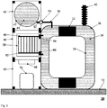
- FIG. 3 shows an exemplary oil transformer 30.
- a transformer with a transformer core 32 and transformer coils 34 is arranged in a vessel 36 which is filled with oil 38.
- An HV bushing 40 is foreseen at the top of the vessel 36.
- a stack of mechanical support structures 46, 48, 50 is foreseen left of the vessel 36.
- An expansion vessel 42 which is partly filled with oil 44, is integrated in the first mechanical support structure 46.
- a fluidic connection in between the expansion vessel 42 and the vessel 36 is realized by a first part 52 leading from the expansion vessel 42 to coupling means 54 and by a second part 56 leading from the coupling means 54 to the vessel 36.
- the second mechanical support structure 48 has cooling means 58 integrated therein, in this case a heat exchanger.
- the heat exchanger comprises several disk like cooling modules which are arranged side by side along the axial length of the mechanical support structure 48. Each cooling module is supplied by a main feed line 64 with oil to be cooled and which is returned after cooling over a main return line 66. Each cooling module has an own feed 60 and return 62 line which are connected to the respective main line 64 respectively 66.
- the third mechanical support structure 50 comprises a fan 68 and control equipment 70, in particular a computer for logging and analyzing measured data of the oil transformer 30. Additionally the stack of the first 46 and second 48 mechanical support structures is lifted up therewith, so that the expansion vessel 42 of the first mechanical support structure is above the top of the vessel 36 therewith. The whole arrangement is placed on a ground floor 72.
Landscapes
- Engineering & Computer Science (AREA)
- Power Engineering (AREA)
- Transformer Cooling (AREA)
Claims (10)
- Transformateur à huile (30), comprenant:• un transformateur à haute tension (32 + 34) disposé dans un récipient rempli d'huile (36),• un vase d'expansion (42),• une liaison fluidique (52 + 54 + 56) entre le vase d'expansion (42) et le récipient rempli d'huile (36),• au moins un moyen de refroidissement (58),ce transformateur à huile (30) comprenant en outre :• un premier module comprenant le vase d'expansion (42) et une structure de support mécanique (10, 22, 24, 46) qui comprend au moins une barre creuse, le vase d'expansion (42) étant intégré de manière fixe dans cette structure de support mécanique (10, 22, 24, 46) comprenant ladite barre creuse, qui a quatre points de coin supérieurs (12, 16) et quatre points de coin inférieurs (14, 28) disposés sous la forme d'un carré, ces points de coin (12, 14, 26, 28) étant chacun sous la forme de points de transfert de charge,
caractérisé en ce que• les points de coin (12, 14, 26, 28) sont disposés en fonction des dimensions d'un conteneur CSC, c'est-à-dire Convention sur la sécurité des conteneurs, de manière à ce que le premier module puisse être transporté exactement comme un conteneur CSC,• la structure de support mécanique ayant des dimensions extérieures comme ledit conteneur CSC,• ladite barre creuse étant une barre creuse porteuse de charge, qui est aussi porteuse de charge comme prévu comme faisant partie de la liaison fluidique (52 + 54 + 56) entre le vase d'expansion (42) et le récipient rempli d'huile (36),• la fonctionnalité d'un tuyau étant intégrée dans ladite barre creuse, et• la structure de support mécanique (10, 22, 24, 46) comprenant des moyens de liaison (54) au niveau de sa surface extérieure qui sont prévus comme faisant partie de la liaison fluidique (52 + 54 + 56) entre le vase d'expansion (42) et le récipient rempli d'huile (36). - Transformateur à huile selon la revendication 1, ce transformateur à huile (30) comprenant en outre un deuxième module comprenant l'au moins un moyen de refroidissement (58) et une deuxième structure de support mécanique, l'au moins un moyen de refroidissement (58) étant intégré de manière fixe dans la deuxième structure de support mécanique (10, 22, 24, 48) qui a quatre points de coin supérieurs (12, 26) et quatre points de coin inférieurs (14, 28) disposés sous la forme d'un carré, ces points de coin (12, 14, 26, 28) étant chacun sous la forme de points de transfert de charge et étant disposés en fonction des dimensions d'un conteneur CSC, de manière à ce que le deuxième module puisse être transporté exactement comme un conteneur CSC.
- Transformateur à huile selon la revendication 2, dans lequel l'au moins un moyen de refroidissement (58) est un échangeur de chaleur, en particulier un échangeur du chaleur huile-air ou un échangeur de chaleur huile-eau.
- Transformateur à huile selon la revendication 3, dans lequel la structure de support mécanique (10, 22, 24, 48) comprend des moyens de liaison au niveau de sa surface extérieure qui sont prévus comme faisant partie d'une liaison fluidique entre l'échangeur de chaleur (58) et le récipient rempli d'huile (36).
- Transformateur à huile selon la revendication 2, dans lequel l'au moins un moyen de refroidissement (58) consiste en un ou plusieurs radiateurs.
- Transformateur à huile selon la revendication 5, dans lequel les radiateurs sont divisés en deux groupes, qui sont prévus pour être utilisés indépendamment l'un de l'autre.
- Transformateur à huile selon l'une quelconque des revendications précédentes, ce transformateur à huile (30) comprenant en outre un troisième module comprenant un matériel de commande et une troisième structure de support mécanique, ce matériel de commande étant intégré de manière fixe dans la troisième structure de support mécanique (10, 22, 24, 50) qui a quatre points de coin supérieurs (12, 26) et quatre points de coin inférieurs (14, 28) disposés sous la forme d'un carré, ces points de coin (12, 14, 26, 28) étant chacun sous la forme de points de transfert de charge et étant disposés en fonction des dimensions du conteneur CSC, de manière à ce que le troisième module puisse être transporté exactement comme un conteneur CSC.
- Transformateur à huile selon l'une quelconque des revendications précédentes 2 à 6, dans lequel au moins deux structures de support mécanique (10, 22, 24, 46, 48, 50) sont empilées chacune l'une sur l'autre.
- Transformateur à huile selon la revendication 8, dans lequel une structure de support mécanique respective (10, 22, 24, 46) avec le vase d'expansion (42) est empilée au-dessus de la deuxième structure de support mécanique (10, 22, 24, 46, 48) avec l'au moins un moyen de refroidissement (58).
- Transformateur à huile selon l'une quelconque des revendications précédentes, dans lequel au moins une structure de support mécanique (10, 22, 24, 46, 48, 50) est disposée côte à côte avec le récipient rempli d'huile (36).
Priority Applications (1)
| Application Number | Priority Date | Filing Date | Title |
|---|---|---|---|
| EP15155155.3A EP3057112B1 (fr) | 2015-02-16 | 2015-02-16 | Transformateur à huile |
Applications Claiming Priority (1)
| Application Number | Priority Date | Filing Date | Title |
|---|---|---|---|
| EP15155155.3A EP3057112B1 (fr) | 2015-02-16 | 2015-02-16 | Transformateur à huile |
Publications (2)
| Publication Number | Publication Date |
|---|---|
| EP3057112A1 EP3057112A1 (fr) | 2016-08-17 |
| EP3057112B1 true EP3057112B1 (fr) | 2020-05-20 |
Family
ID=52589238
Family Applications (1)
| Application Number | Title | Priority Date | Filing Date |
|---|---|---|---|
| EP15155155.3A Active EP3057112B1 (fr) | 2015-02-16 | 2015-02-16 | Transformateur à huile |
Country Status (1)
| Country | Link |
|---|---|
| EP (1) | EP3057112B1 (fr) |
Families Citing this family (3)
| Publication number | Priority date | Publication date | Assignee | Title |
|---|---|---|---|---|
| DK3711074T3 (da) | 2018-01-15 | 2022-06-07 | Siemens Energy Global Gmbh & Co Kg | Effekttransformatorenhed, der kan transporteres |
| BR112021021202A2 (pt) | 2019-03-22 | 2022-01-04 | Efacec Energia Maqu E Equipamentos Electricos S A | Sistema modular aplicado a transformadores |
| EP3940727B1 (fr) | 2020-07-13 | 2024-09-04 | Hitachi Energy Ltd | Agencement à induction électrique statique |
Family Cites Families (10)
| Publication number | Priority date | Publication date | Assignee | Title |
|---|---|---|---|---|
| GB383541A (en) * | 1931-04-15 | 1932-11-17 | Gen Electric | Improvements in and relating to expansion chambers for fluid filled apparatus |
| GB845102A (en) * | 1955-04-19 | 1960-08-17 | Geoffrey Wells Leaper | Improvements in or relating to pressure equalisation devices for closed vessels |
| FR76234E (fr) * | 1959-08-07 | 1961-09-29 | Electricite De France | Perfectionnement aux transformateurs électriques dans l'huile |
| DE1465149B2 (de) * | 1964-03-18 | 1970-11-26 | Allmänna Svenska Elektriska AB, Västeras (Schweden) | Expansionsgefäß für ölkabel |
| DE19614775C2 (de) * | 1996-04-03 | 1999-05-20 | Aeg Schorch Transformatoren Gm | Ausdehnungsgefäß für die Kühl- und Isolierflüssigkeit eines Transformators oder einer Drosselspule |
| PL1905052T3 (pl) * | 2005-07-15 | 2017-08-31 | Siemens Aktiengesellschaft | Naczynie rozszerzalnościowe do przełącznika stopniowego |
| US20090242552A1 (en) * | 2008-04-01 | 2009-10-01 | Myers Gerald D | Iso container having a load transfer plate |
| EP2133889A1 (fr) * | 2008-06-12 | 2009-12-16 | ABB Technology AG | Bobine d'arrêt et agencement de vérification comportant la bobine d'arrêt |
| EP2169690B1 (fr) * | 2008-09-24 | 2012-08-29 | ABB Technology AG | Compensateur de pression |
| ES2460628T3 (es) * | 2011-11-02 | 2014-05-14 | Abb Technology Ag | Módulo de transformador de alta tensión |
-
2015
- 2015-02-16 EP EP15155155.3A patent/EP3057112B1/fr active Active
Non-Patent Citations (1)
| Title |
|---|
| None * |
Also Published As
| Publication number | Publication date |
|---|---|
| EP3057112A1 (fr) | 2016-08-17 |
Similar Documents
| Publication | Publication Date | Title |
|---|---|---|
| KR102687934B1 (ko) | 모듈식 프로세스 구조 시스템 | |
| AU2015363808B2 (en) | High temperature thermal energy storage, a method of building and a method of operating said storage | |
| EP2151833B1 (fr) | Système de transformateur | |
| CA2958928A1 (fr) | Systeme electrique sous-marin compense en pression | |
| ES2391252T3 (es) | Método híbrido de montaje de una caja fría empleando componentes prefabricados y montados en campo | |
| EP3057112A1 (fr) | Transformateur à huile | |
| CN114096478A (zh) | 用于堆叠作为能量转换设备的部件的壳体的集装箱的平台、和能量转换设备 | |
| EP2824822A1 (fr) | Système de transmission et de distribution d'énergie fournissant une pluralité de charges sous-marines | |
| CN104025216B (zh) | 高压变压器模块 | |
| JP2018526620A (ja) | 制御棒位置指示器 | |
| EP3649658B1 (fr) | Procédé d'entretien de transformateur et agencement de transformateur | |
| CN103975657B (zh) | 测试集装箱 | |
| EP2988579A1 (fr) | Configuration de refroidissement d'huile pour un système sous-marin électronique | |
| US20200106274A1 (en) | Electrical substation, installation and method of implemention | |
| CN103975399A (zh) | 油浸变压器 | |
| CN107068343A (zh) | 一种强迫导向冷却三相油浸式配电变压器 | |
| US9696029B2 (en) | Method for erecting a boiler, module and boiler comprising the module | |
| CN120313395A (zh) | 一种能用集装箱运输的固体蓄热体及塔式安装方法 | |
| US20160247619A1 (en) | Vibration stabilizer for enclosure cooling fins | |
| WO2023110300A1 (fr) | Dispositif d'induction électrique statique et procédé de fonctionnement | |
| DK2733265T3 (en) | Cooling system for a transformer platform | |
| CN106710812A (zh) | 一种智能三相油浸式配电变压器 | |
| CN202771905U (zh) | 一种10kv油浸式电力变压器 | |
| CN210685518U (zh) | 电厂主厂房 | |
| US11908602B2 (en) | Static electric induction arrangement |
Legal Events
| Date | Code | Title | Description |
|---|---|---|---|
| PUAI | Public reference made under article 153(3) epc to a published international application that has entered the european phase |
Free format text: ORIGINAL CODE: 0009012 |
|
| AK | Designated contracting states |
Kind code of ref document: A1 Designated state(s): AL AT BE BG CH CY CZ DE DK EE ES FI FR GB GR HR HU IE IS IT LI LT LU LV MC MK MT NL NO PL PT RO RS SE SI SK SM TR |
|
| AX | Request for extension of the european patent |
Extension state: BA ME |
|
| RAP1 | Party data changed (applicant data changed or rights of an application transferred) |
Owner name: ABB SCHWEIZ AG |
|
| STAA | Information on the status of an ep patent application or granted ep patent |
Free format text: STATUS: REQUEST FOR EXAMINATION WAS MADE |
|
| 17P | Request for examination filed |
Effective date: 20161220 |
|
| RIN1 | Information on inventor provided before grant (corrected) |
Inventor name: DUELLBERG, ULRICH Inventor name: SCHMIDT, THOMAS |
|
| STAA | Information on the status of an ep patent application or granted ep patent |
Free format text: STATUS: EXAMINATION IS IN PROGRESS |
|
| 17Q | First examination report despatched |
Effective date: 20170516 |
|
| GRAP | Despatch of communication of intention to grant a patent |
Free format text: ORIGINAL CODE: EPIDOSNIGR1 |
|
| STAA | Information on the status of an ep patent application or granted ep patent |
Free format text: STATUS: GRANT OF PATENT IS INTENDED |
|
| INTG | Intention to grant announced |
Effective date: 20191218 |
|
| GRAJ | Information related to disapproval of communication of intention to grant by the applicant or resumption of examination proceedings by the epo deleted |
Free format text: ORIGINAL CODE: EPIDOSDIGR1 |
|
| STAA | Information on the status of an ep patent application or granted ep patent |
Free format text: STATUS: EXAMINATION IS IN PROGRESS |
|
| GRAP | Despatch of communication of intention to grant a patent |
Free format text: ORIGINAL CODE: EPIDOSNIGR1 |
|
| STAA | Information on the status of an ep patent application or granted ep patent |
Free format text: STATUS: GRANT OF PATENT IS INTENDED |
|
| RAP1 | Party data changed (applicant data changed or rights of an application transferred) |
Owner name: ABB POWER GRIDS SWITZERLAND AG |
|
| GRAS | Grant fee paid |
Free format text: ORIGINAL CODE: EPIDOSNIGR3 |
|
| GRAA | (expected) grant |
Free format text: ORIGINAL CODE: 0009210 |
|
| STAA | Information on the status of an ep patent application or granted ep patent |
Free format text: STATUS: THE PATENT HAS BEEN GRANTED |
|
| INTC | Intention to grant announced (deleted) | ||
| INTG | Intention to grant announced |
Effective date: 20200401 |
|
| AK | Designated contracting states |
Kind code of ref document: B1 Designated state(s): AL AT BE BG CH CY CZ DE DK EE ES FI FR GB GR HR HU IE IS IT LI LT LU LV MC MK MT NL NO PL PT RO RS SE SI SK SM TR |
|
| REG | Reference to a national code |
Ref country code: GB Ref legal event code: FG4D |
|
| REG | Reference to a national code |
Ref country code: CH Ref legal event code: EP |
|
| REG | Reference to a national code |
Ref country code: DE Ref legal event code: R096 Ref document number: 602015052969 Country of ref document: DE |
|
| REG | Reference to a national code |
Ref country code: AT Ref legal event code: REF Ref document number: 1273151 Country of ref document: AT Kind code of ref document: T Effective date: 20200615 |
|
| REG | Reference to a national code |
Ref country code: LT Ref legal event code: MG4D |
|
| REG | Reference to a national code |
Ref country code: NL Ref legal event code: MP Effective date: 20200520 |
|
| PG25 | Lapsed in a contracting state [announced via postgrant information from national office to epo] |
Ref country code: LT Free format text: LAPSE BECAUSE OF FAILURE TO SUBMIT A TRANSLATION OF THE DESCRIPTION OR TO PAY THE FEE WITHIN THE PRESCRIBED TIME-LIMIT Effective date: 20200520 Ref country code: IS Free format text: LAPSE BECAUSE OF FAILURE TO SUBMIT A TRANSLATION OF THE DESCRIPTION OR TO PAY THE FEE WITHIN THE PRESCRIBED TIME-LIMIT Effective date: 20200920 Ref country code: SE Free format text: LAPSE BECAUSE OF FAILURE TO SUBMIT A TRANSLATION OF THE DESCRIPTION OR TO PAY THE FEE WITHIN THE PRESCRIBED TIME-LIMIT Effective date: 20200520 Ref country code: PT Free format text: LAPSE BECAUSE OF FAILURE TO SUBMIT A TRANSLATION OF THE DESCRIPTION OR TO PAY THE FEE WITHIN THE PRESCRIBED TIME-LIMIT Effective date: 20200921 Ref country code: FI Free format text: LAPSE BECAUSE OF FAILURE TO SUBMIT A TRANSLATION OF THE DESCRIPTION OR TO PAY THE FEE WITHIN THE PRESCRIBED TIME-LIMIT Effective date: 20200520 Ref country code: GR Free format text: LAPSE BECAUSE OF FAILURE TO SUBMIT A TRANSLATION OF THE DESCRIPTION OR TO PAY THE FEE WITHIN THE PRESCRIBED TIME-LIMIT Effective date: 20200821 Ref country code: NO Free format text: LAPSE BECAUSE OF FAILURE TO SUBMIT A TRANSLATION OF THE DESCRIPTION OR TO PAY THE FEE WITHIN THE PRESCRIBED TIME-LIMIT Effective date: 20200820 |
|
| PG25 | Lapsed in a contracting state [announced via postgrant information from national office to epo] |
Ref country code: BG Free format text: LAPSE BECAUSE OF FAILURE TO SUBMIT A TRANSLATION OF THE DESCRIPTION OR TO PAY THE FEE WITHIN THE PRESCRIBED TIME-LIMIT Effective date: 20200820 Ref country code: RS Free format text: LAPSE BECAUSE OF FAILURE TO SUBMIT A TRANSLATION OF THE DESCRIPTION OR TO PAY THE FEE WITHIN THE PRESCRIBED TIME-LIMIT Effective date: 20200520 Ref country code: LV Free format text: LAPSE BECAUSE OF FAILURE TO SUBMIT A TRANSLATION OF THE DESCRIPTION OR TO PAY THE FEE WITHIN THE PRESCRIBED TIME-LIMIT Effective date: 20200520 Ref country code: HR Free format text: LAPSE BECAUSE OF FAILURE TO SUBMIT A TRANSLATION OF THE DESCRIPTION OR TO PAY THE FEE WITHIN THE PRESCRIBED TIME-LIMIT Effective date: 20200520 |
|
| REG | Reference to a national code |
Ref country code: AT Ref legal event code: MK05 Ref document number: 1273151 Country of ref document: AT Kind code of ref document: T Effective date: 20200520 |
|
| PG25 | Lapsed in a contracting state [announced via postgrant information from national office to epo] |
Ref country code: AL Free format text: LAPSE BECAUSE OF FAILURE TO SUBMIT A TRANSLATION OF THE DESCRIPTION OR TO PAY THE FEE WITHIN THE PRESCRIBED TIME-LIMIT Effective date: 20200520 Ref country code: NL Free format text: LAPSE BECAUSE OF FAILURE TO SUBMIT A TRANSLATION OF THE DESCRIPTION OR TO PAY THE FEE WITHIN THE PRESCRIBED TIME-LIMIT Effective date: 20200520 |
|
| PG25 | Lapsed in a contracting state [announced via postgrant information from national office to epo] |
Ref country code: CZ Free format text: LAPSE BECAUSE OF FAILURE TO SUBMIT A TRANSLATION OF THE DESCRIPTION OR TO PAY THE FEE WITHIN THE PRESCRIBED TIME-LIMIT Effective date: 20200520 Ref country code: RO Free format text: LAPSE BECAUSE OF FAILURE TO SUBMIT A TRANSLATION OF THE DESCRIPTION OR TO PAY THE FEE WITHIN THE PRESCRIBED TIME-LIMIT Effective date: 20200520 Ref country code: DK Free format text: LAPSE BECAUSE OF FAILURE TO SUBMIT A TRANSLATION OF THE DESCRIPTION OR TO PAY THE FEE WITHIN THE PRESCRIBED TIME-LIMIT Effective date: 20200520 Ref country code: IT Free format text: LAPSE BECAUSE OF FAILURE TO SUBMIT A TRANSLATION OF THE DESCRIPTION OR TO PAY THE FEE WITHIN THE PRESCRIBED TIME-LIMIT Effective date: 20200520 Ref country code: SM Free format text: LAPSE BECAUSE OF FAILURE TO SUBMIT A TRANSLATION OF THE DESCRIPTION OR TO PAY THE FEE WITHIN THE PRESCRIBED TIME-LIMIT Effective date: 20200520 Ref country code: EE Free format text: LAPSE BECAUSE OF FAILURE TO SUBMIT A TRANSLATION OF THE DESCRIPTION OR TO PAY THE FEE WITHIN THE PRESCRIBED TIME-LIMIT Effective date: 20200520 Ref country code: AT Free format text: LAPSE BECAUSE OF FAILURE TO SUBMIT A TRANSLATION OF THE DESCRIPTION OR TO PAY THE FEE WITHIN THE PRESCRIBED TIME-LIMIT Effective date: 20200520 Ref country code: ES Free format text: LAPSE BECAUSE OF FAILURE TO SUBMIT A TRANSLATION OF THE DESCRIPTION OR TO PAY THE FEE WITHIN THE PRESCRIBED TIME-LIMIT Effective date: 20200520 |
|
| REG | Reference to a national code |
Ref country code: DE Ref legal event code: R097 Ref document number: 602015052969 Country of ref document: DE |
|
| PG25 | Lapsed in a contracting state [announced via postgrant information from national office to epo] |
Ref country code: PL Free format text: LAPSE BECAUSE OF FAILURE TO SUBMIT A TRANSLATION OF THE DESCRIPTION OR TO PAY THE FEE WITHIN THE PRESCRIBED TIME-LIMIT Effective date: 20200520 Ref country code: SK Free format text: LAPSE BECAUSE OF FAILURE TO SUBMIT A TRANSLATION OF THE DESCRIPTION OR TO PAY THE FEE WITHIN THE PRESCRIBED TIME-LIMIT Effective date: 20200520 |
|
| PLBE | No opposition filed within time limit |
Free format text: ORIGINAL CODE: 0009261 |
|
| STAA | Information on the status of an ep patent application or granted ep patent |
Free format text: STATUS: NO OPPOSITION FILED WITHIN TIME LIMIT |
|
| 26N | No opposition filed |
Effective date: 20210223 |
|
| PG25 | Lapsed in a contracting state [announced via postgrant information from national office to epo] |
Ref country code: SI Free format text: LAPSE BECAUSE OF FAILURE TO SUBMIT A TRANSLATION OF THE DESCRIPTION OR TO PAY THE FEE WITHIN THE PRESCRIBED TIME-LIMIT Effective date: 20200520 |
|
| PG25 | Lapsed in a contracting state [announced via postgrant information from national office to epo] |
Ref country code: MC Free format text: LAPSE BECAUSE OF FAILURE TO SUBMIT A TRANSLATION OF THE DESCRIPTION OR TO PAY THE FEE WITHIN THE PRESCRIBED TIME-LIMIT Effective date: 20200520 |
|
| GBPC | Gb: european patent ceased through non-payment of renewal fee |
Effective date: 20210216 |
|
| REG | Reference to a national code |
Ref country code: BE Ref legal event code: MM Effective date: 20210228 |
|
| PG25 | Lapsed in a contracting state [announced via postgrant information from national office to epo] |
Ref country code: LU Free format text: LAPSE BECAUSE OF NON-PAYMENT OF DUE FEES Effective date: 20210216 Ref country code: LI Free format text: LAPSE BECAUSE OF NON-PAYMENT OF DUE FEES Effective date: 20210228 Ref country code: CH Free format text: LAPSE BECAUSE OF NON-PAYMENT OF DUE FEES Effective date: 20210228 |
|
| PG25 | Lapsed in a contracting state [announced via postgrant information from national office to epo] |
Ref country code: FR Free format text: LAPSE BECAUSE OF NON-PAYMENT OF DUE FEES Effective date: 20210228 Ref country code: IE Free format text: LAPSE BECAUSE OF NON-PAYMENT OF DUE FEES Effective date: 20210216 Ref country code: GB Free format text: LAPSE BECAUSE OF NON-PAYMENT OF DUE FEES Effective date: 20210216 |
|
| REG | Reference to a national code |
Ref country code: DE Ref legal event code: R081 Ref document number: 602015052969 Country of ref document: DE Owner name: HITACHI ENERGY SWITZERLAND AG, CH Free format text: FORMER OWNER: ABB POWER GRIDS SWITZERLAND AG, BADEN, CH Ref country code: DE Ref legal event code: R081 Ref document number: 602015052969 Country of ref document: DE Owner name: HITACHI ENERGY LTD, CH Free format text: FORMER OWNER: ABB POWER GRIDS SWITZERLAND AG, BADEN, CH |
|
| PG25 | Lapsed in a contracting state [announced via postgrant information from national office to epo] |
Ref country code: BE Free format text: LAPSE BECAUSE OF NON-PAYMENT OF DUE FEES Effective date: 20210228 |
|
| PG25 | Lapsed in a contracting state [announced via postgrant information from national office to epo] |
Ref country code: HU Free format text: LAPSE BECAUSE OF FAILURE TO SUBMIT A TRANSLATION OF THE DESCRIPTION OR TO PAY THE FEE WITHIN THE PRESCRIBED TIME-LIMIT; INVALID AB INITIO Effective date: 20150216 |
|
| PG25 | Lapsed in a contracting state [announced via postgrant information from national office to epo] |
Ref country code: CY Free format text: LAPSE BECAUSE OF FAILURE TO SUBMIT A TRANSLATION OF THE DESCRIPTION OR TO PAY THE FEE WITHIN THE PRESCRIBED TIME-LIMIT Effective date: 20200520 |
|
| P01 | Opt-out of the competence of the unified patent court (upc) registered |
Effective date: 20230527 |
|
| REG | Reference to a national code |
Ref country code: DE Ref legal event code: R082 Ref document number: 602015052969 Country of ref document: DE Representative=s name: DENNEMEYER & ASSOCIATES RECHTSANWALTSGESELLSCH, DE Ref country code: DE Ref legal event code: R082 Ref document number: 602015052969 Country of ref document: DE Representative=s name: DENNEMEYER & ASSOCIATES S.A., DE Ref country code: DE Ref legal event code: R081 Ref document number: 602015052969 Country of ref document: DE Owner name: HITACHI ENERGY LTD, CH Free format text: FORMER OWNER: HITACHI ENERGY SWITZERLAND AG, BADEN, CH |
|
| PG25 | Lapsed in a contracting state [announced via postgrant information from national office to epo] |
Ref country code: MK Free format text: LAPSE BECAUSE OF FAILURE TO SUBMIT A TRANSLATION OF THE DESCRIPTION OR TO PAY THE FEE WITHIN THE PRESCRIBED TIME-LIMIT Effective date: 20200520 |
|
| PG25 | Lapsed in a contracting state [announced via postgrant information from national office to epo] |
Ref country code: TR Free format text: LAPSE BECAUSE OF FAILURE TO SUBMIT A TRANSLATION OF THE DESCRIPTION OR TO PAY THE FEE WITHIN THE PRESCRIBED TIME-LIMIT Effective date: 20200520 |
|
| PG25 | Lapsed in a contracting state [announced via postgrant information from national office to epo] |
Ref country code: MT Free format text: LAPSE BECAUSE OF FAILURE TO SUBMIT A TRANSLATION OF THE DESCRIPTION OR TO PAY THE FEE WITHIN THE PRESCRIBED TIME-LIMIT Effective date: 20200520 |
|
| REG | Reference to a national code |
Ref country code: DE Ref legal event code: R082 Ref document number: 602015052969 Country of ref document: DE Representative=s name: DENNEMEYER & ASSOCIATES RECHTSANWALTSGESELLSCH, DE |
|
| PGFP | Annual fee paid to national office [announced via postgrant information from national office to epo] |
Ref country code: DE Payment date: 20260218 Year of fee payment: 12 |