EP3057184A1 - Procédé et dispositif de fabrication d'un câble ainsi qu'un câble fabriqué selon ledit procédé - Google Patents
Procédé et dispositif de fabrication d'un câble ainsi qu'un câble fabriqué selon ledit procédé Download PDFInfo
- Publication number
- EP3057184A1 EP3057184A1 EP15154587.8A EP15154587A EP3057184A1 EP 3057184 A1 EP3057184 A1 EP 3057184A1 EP 15154587 A EP15154587 A EP 15154587A EP 3057184 A1 EP3057184 A1 EP 3057184A1
- Authority
- EP
- European Patent Office
- Prior art keywords
- conductor
- tool
- crimping
- cable
- sleeve
- Prior art date
- Legal status (The legal status is an assumption and is not a legal conclusion. Google has not performed a legal analysis and makes no representation as to the accuracy of the status listed.)
- Granted
Links
Images


Classifications
-
- H—ELECTRICITY
- H01—ELECTRIC ELEMENTS
- H01R—ELECTRICALLY-CONDUCTIVE CONNECTIONS; STRUCTURAL ASSOCIATIONS OF A PLURALITY OF MUTUALLY-INSULATED ELECTRICAL CONNECTING ELEMENTS; COUPLING DEVICES; CURRENT COLLECTORS
- H01R43/00—Apparatus or processes specially adapted for manufacturing, assembling, maintaining, or repairing of line connectors or current collectors or for joining electric conductors
- H01R43/04—Apparatus or processes specially adapted for manufacturing, assembling, maintaining, or repairing of line connectors or current collectors or for joining electric conductors for forming connections by deformation, e.g. crimping tool
- H01R43/048—Crimping apparatus or processes
-
- H—ELECTRICITY
- H01—ELECTRIC ELEMENTS
- H01R—ELECTRICALLY-CONDUCTIVE CONNECTIONS; STRUCTURAL ASSOCIATIONS OF A PLURALITY OF MUTUALLY-INSULATED ELECTRICAL CONNECTING ELEMENTS; COUPLING DEVICES; CURRENT COLLECTORS
- H01R4/00—Electrically-conductive connections between two or more conductive members in direct contact, i.e. touching one another; Means for effecting or maintaining such contact; Electrically-conductive connections having two or more spaced connecting locations for conductors and using contact members penetrating insulation
- H01R4/10—Electrically-conductive connections between two or more conductive members in direct contact, i.e. touching one another; Means for effecting or maintaining such contact; Electrically-conductive connections having two or more spaced connecting locations for conductors and using contact members penetrating insulation effected solely by twisting, wrapping, bending, crimping, or other permanent deformation
- H01R4/18—Electrically-conductive connections between two or more conductive members in direct contact, i.e. touching one another; Means for effecting or maintaining such contact; Electrically-conductive connections having two or more spaced connecting locations for conductors and using contact members penetrating insulation effected solely by twisting, wrapping, bending, crimping, or other permanent deformation by crimping
- H01R4/20—Electrically-conductive connections between two or more conductive members in direct contact, i.e. touching one another; Means for effecting or maintaining such contact; Electrically-conductive connections having two or more spaced connecting locations for conductors and using contact members penetrating insulation effected solely by twisting, wrapping, bending, crimping, or other permanent deformation by crimping using a crimping sleeve
-
- H—ELECTRICITY
- H01—ELECTRIC ELEMENTS
- H01R—ELECTRICALLY-CONDUCTIVE CONNECTIONS; STRUCTURAL ASSOCIATIONS OF A PLURALITY OF MUTUALLY-INSULATED ELECTRICAL CONNECTING ELEMENTS; COUPLING DEVICES; CURRENT COLLECTORS
- H01R11/00—Individual connecting elements providing two or more spaced connecting locations for conductive members which are, or may be, thereby interconnected, e.g. end pieces for wires or cables supported by the wire or cable and having means for facilitating electrical connection to some other wire, terminal, or conductive member, blocks of binding posts
- H01R11/11—End pieces or tapping pieces for wires, supported by the wire and for facilitating electrical connection to some other wire, terminal or conductive member
-
- H—ELECTRICITY
- H01—ELECTRIC ELEMENTS
- H01R—ELECTRICALLY-CONDUCTIVE CONNECTIONS; STRUCTURAL ASSOCIATIONS OF A PLURALITY OF MUTUALLY-INSULATED ELECTRICAL CONNECTING ELEMENTS; COUPLING DEVICES; CURRENT COLLECTORS
- H01R4/00—Electrically-conductive connections between two or more conductive members in direct contact, i.e. touching one another; Means for effecting or maintaining such contact; Electrically-conductive connections having two or more spaced connecting locations for conductors and using contact members penetrating insulation
- H01R4/10—Electrically-conductive connections between two or more conductive members in direct contact, i.e. touching one another; Means for effecting or maintaining such contact; Electrically-conductive connections having two or more spaced connecting locations for conductors and using contact members penetrating insulation effected solely by twisting, wrapping, bending, crimping, or other permanent deformation
- H01R4/18—Electrically-conductive connections between two or more conductive members in direct contact, i.e. touching one another; Means for effecting or maintaining such contact; Electrically-conductive connections having two or more spaced connecting locations for conductors and using contact members penetrating insulation effected solely by twisting, wrapping, bending, crimping, or other permanent deformation by crimping
-
- H—ELECTRICITY
- H01—ELECTRIC ELEMENTS
- H01R—ELECTRICALLY-CONDUCTIVE CONNECTIONS; STRUCTURAL ASSOCIATIONS OF A PLURALITY OF MUTUALLY-INSULATED ELECTRICAL CONNECTING ELEMENTS; COUPLING DEVICES; CURRENT COLLECTORS
- H01R43/00—Apparatus or processes specially adapted for manufacturing, assembling, maintaining, or repairing of line connectors or current collectors or for joining electric conductors
- H01R43/04—Apparatus or processes specially adapted for manufacturing, assembling, maintaining, or repairing of line connectors or current collectors or for joining electric conductors for forming connections by deformation, e.g. crimping tool
- H01R43/048—Crimping apparatus or processes
- H01R43/05—Crimping apparatus or processes with wire-insulation stripping
-
- H—ELECTRICITY
- H01—ELECTRIC ELEMENTS
- H01R—ELECTRICALLY-CONDUCTIVE CONNECTIONS; STRUCTURAL ASSOCIATIONS OF A PLURALITY OF MUTUALLY-INSULATED ELECTRICAL CONNECTING ELEMENTS; COUPLING DEVICES; CURRENT COLLECTORS
- H01R43/00—Apparatus or processes specially adapted for manufacturing, assembling, maintaining, or repairing of line connectors or current collectors or for joining electric conductors
- H01R43/04—Apparatus or processes specially adapted for manufacturing, assembling, maintaining, or repairing of line connectors or current collectors or for joining electric conductors for forming connections by deformation, e.g. crimping tool
- H01R43/058—Crimping mandrels
-
- H—ELECTRICITY
- H02—GENERATION; CONVERSION OR DISTRIBUTION OF ELECTRIC POWER
- H02G—INSTALLATION OF ELECTRIC CABLES OR LINES, OR OF COMBINED OPTICAL AND ELECTRIC CABLES OR LINES
- H02G1/00—Methods or apparatus specially adapted for installing, maintaining, repairing or dismantling electric cables or lines
- H02G1/12—Methods or apparatus specially adapted for installing, maintaining, repairing or dismantling electric cables or lines for removing insulation or armouring from cables, e.g. from the end thereof
- H02G1/1275—Methods or apparatus specially adapted for installing, maintaining, repairing or dismantling electric cables or lines for removing insulation or armouring from cables, e.g. from the end thereof by applying heat
-
- H—ELECTRICITY
- H01—ELECTRIC ELEMENTS
- H01R—ELECTRICALLY-CONDUCTIVE CONNECTIONS; STRUCTURAL ASSOCIATIONS OF A PLURALITY OF MUTUALLY-INSULATED ELECTRICAL CONNECTING ELEMENTS; COUPLING DEVICES; CURRENT COLLECTORS
- H01R2201/00—Connectors or connections adapted for particular applications
- H01R2201/26—Connectors or connections adapted for particular applications for vehicles
-
- H—ELECTRICITY
- H02—GENERATION; CONVERSION OR DISTRIBUTION OF ELECTRIC POWER
- H02G—INSTALLATION OF ELECTRIC CABLES OR LINES, OR OF COMBINED OPTICAL AND ELECTRIC CABLES OR LINES
- H02G1/00—Methods or apparatus specially adapted for installing, maintaining, repairing or dismantling electric cables or lines
- H02G1/12—Methods or apparatus specially adapted for installing, maintaining, repairing or dismantling electric cables or lines for removing insulation or armouring from cables, e.g. from the end thereof
- H02G1/1202—Methods or apparatus specially adapted for installing, maintaining, repairing or dismantling electric cables or lines for removing insulation or armouring from cables, e.g. from the end thereof by cutting and withdrawing insulation
- H02G1/1248—Machines
- H02G1/1251—Machines the cutting element not rotating about the wire or cable
- H02G1/1253—Machines the cutting element not rotating about the wire or cable making a transverse cut
Definitions
- the invention relates to a method for producing a prefabricated cable according to claim 1. Furthermore, the invention comprises a device for producing or assembling such a cable according to claim 10 and a manufactured with the method or with the device cable according to claim 15.
- the cables in question are used for example in motor vehicles or aircraft and are usually needed in large quantities. For cost-effective provision of appropriate cables a simple structure and ease of assembly are of great importance.
- WO 03/097289 A1 For example, a method of manufacturing a cable is known in which an unstripped end of the electrical conductor is connected to a contact partner, the connection area is heated and then compressed.
- the invention has for its object to provide a method for the production of high-quality cables, which allows to produce cables with comparatively low production cost.
- the invention also includes a novel apparatus for making such high quality cables and cables made by the method.
- the crimping process is performed immediately following the heating of the conductor.
- the heating of the conductor is made so that it is heated to the desired temperature in a very short time. Accordingly, the heating is performed with comparatively high power.
- the heating of the conductor is performed by an induction process.
- a first tool is preferably moved along a z-direction relative to a second tool, and the first tool and / or the second tool are heated.
- the sleeve is crimped with the conductor using a first tool having a first crimping surface and a second tool having a second crimping surface.
- the first tool is moved along a z-direction relative to the second tool.
- the first tool or the second tool or both tools are heated, wherein the heating or a temperature control of the conductor is effected by the contact with the heated tool.
- the timing of the crimping process is also adjusted in this embodiment of the method so that the conductor has reached the required processing temperature before the crimping process is completed.
- the crimping surfaces are those surfaces of the tools which are brought into contact with the sleeve or with the conductor during the crimping process.
- the crimping surfaces can be treated, in particular coated, to optimize the service life of the tools, so that the friction coefficient and the static friction wear are reduced.
- material deposits and cold welding can be reduced or avoided in the course of the operating time by a suitable coating of the crimping surfaces of the tools.
- the insulation is at least partially removed before carrying out the heating.
- the insulation is removed at that axial portion of the cable, at which subsequently the sleeve is electrically contacted with the conductor.
- the crimping process is designed so that the expansion of the compression of the conductor, starting from the first axial section takes place axially to both sides of the first axial section.
- the conductor can not be stripped before performing the crimping process, so that possibly due to the high temperature of the conductor in conjunction with one or more heated tools, the soft or liquid material of the insulation is axially displaced during the crimping process.
- the material of the insulation comprises ethylene vinyl acetate (EVA) or PEVA (polyethylene-vinyl acetate).
- the conductor is designed so that its individual wires have a lay length of at least 12 mm, in particular of at least 20 mm, in particular of at least 30 mm.
- lay length describes the length of the distance that a single wire of the ladder requires for a 360 ° turn.
- the conductor of a core preferably has at least 10 individual wires, in particular at least 20 individual wires.
- the crimping process is advantageously carried out at a temperature of the conductor of more than 60 ° C., preferably at a temperature of over 150 ° C., in particular at a temperature of over 200 ° C. In particular, it is advantageous if the crimping process is carried out at a temperature of the conductor which is above the melting temperature of the material of the insulation.
- the cable has a plurality of conductors, each comprising a plurality of individual wires.
- the conductors are at least partially surrounded by insulation.
- the cable also has a plurality of sleeves, wherein in a heated conductor of the crimping process for electrically contacting the sleeve is performed while at the same time another conductor is heated, in preparation for the crimping process for the other conductor.
- the invention also relates to a device for producing a cable, which has a conductor, in particular with a plurality of individual wires, wherein the conductor is electrically contacted with a sleeve by a crimp connection.
- the device comprises a heating device for heating the conductor.
- the device has a first tool with a first Crimp surface and a second tool with a second crimping surface.
- the first tool is movable along a z-direction over a machining stroke relative to the second tool.
- the crimping surfaces are arranged opposite one another over an axial length in the z-direction.
- pairs of points each comprise a first point on the first crimping surface and a second point on the second crimping surface.
- the two points of a pair of points are arranged in the z-direction opposite each other, for axially spaced pairs of points, the distances in the z-direction between the associated points of a pair of points are different in size.
- axial means in the direction of the longitudinal axis of the conductor to be crimped, ie orthogonal to the z-direction.
- the conductor is usually at least partially so surrounded in an axial section of insulation.
- the heating device is designed as an induction heating device, in particular, the heating device has an electromagnetic coil.
- the first tool or the second tool is heated.
- both tools can be heated.
- the heating device can be designed as an electrical resistance heater for heating the first and / or the second tool.
- the first tool and / or the second tool comprises a plurality of sub-elements, wherein each of the sub-elements has a crimping surface.
- the sub-elements of the first tool are arranged in the z-direction relative to each other displaceable.
- the sub-elements of the second tool in the z-direction can be arranged relative to each other displaced.
- the device may be configured so that for the production of the crimped connection, the first tool is movable along the z-direction relative to the second tool within a machining stroke, with increasing approach of the tools to each other, the differences in the distances between points that are axially spaced apart Pair of points belonging, become smaller.
- at least one subelement of a tool at least precedes at least one other subelement of the same tool in the movement in the z direction ahead of time.
- the invention also relates to a cable produced by the process according to the invention, which has a conductor with a plurality of individual wires, which is at least partially surrounded by an insulation, wherein the cable also has a sleeve which is electrically contacted with the conductor by a crimp connection.
- the invention it is possible to produce high quality cables.
- a cable is created which has a largely residue-free crimp connection.
- the invention is particularly advantageous for cables with a comparatively long lay length and with a large number of individual wires.
- FIG. 1a a side view of one end of a cable is shown, which is to be edited or assembled.
- the jacket 5 being made of electrically insulating material, for example of a thermoplastic elastomer, in particular urethane-based.
- the cable has four twisted wires 1, 2, 3, 4 in the illustrated embodiment.
- the wires 1, 2, 3, 4 each comprise an inner conductor 1.1, 2.1, 3.1, 4.1 ( FIG. 1 b) , wherein each of the conductors 1.1, 2.1, 3.1, 4.1 consists of a plurality of stranded individual wires. In the presented embodiment, the lay length is 20 mm.
- Each of the wires 1, 2, 3, 4 or each conductor 1.1, 2.1, 1.3, 4.1 here has 27 individual wires.
- Each conductor 1.1, 2.1, 3.1, 4.1 is surrounded by an insulation 1.2, 2.2, 3.2, 4.2 respectively.
- the material for the insulation 1.2, 2.2, 3.2, 4.2 is in the presented embodiment, ethylene vinyl acetate (EVA).
- EVA ethylene vinyl acetate
- the end of the cable is first processed in a device for producing the ready-made cable with a cutting tool 13 ( FIG. 1a ).
- the cutting tool comprises two cutting blades 13.1, 13.2, which have a V-shaped shape for gripping the jacket 5.
- the cutting blades 13.1, 13.2 are made to approach each other orthogonally to the longitudinal axis of the cable until the cutting blades 13.1, 13.2 have penetrated into the jacket 5 with sufficient depth.
- the end of the jacket 5 is withdrawn in the axial direction, so that finally according to the FIG. 2 the jacket 5 is removed at one end of the cable and there the inner wires 1, 2, 3, 4 are exposed.
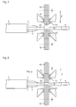
- the wires 1, 2, 3, 4 according to the FIG. 3 largely stretched and arranged according to a fork shape, so that the ends of the wires 1, 2, 3, 4 lie in a plane.
- the ends of the wires 1, 2, 3, 4 each have a longitudinal axis A1, A2, A3, A4, wherein the longitudinal axes A1, A2, A3, A4 are arranged substantially parallel to one another and correspondingly in a plane.
- the wires 1, 2, 3, 4 are first according to the FIG. 4 cut off along a line L1. Thereafter, the ends of the wires 1, 2, 3, 4 stripped away over a length xc away, so that the conductors 1.1, 2.1, 3.1, 4.1 are exposed there.
- the conductors 1.1, 2.1, 3.1, 4.1 comprise, as mentioned above, twisted individual wires, wherein in the figures for clarity, the explicit representation of the individual wires was omitted.
- a heating device 10 which is designed substantially hollow cylindrical, pushed over the first conductor 1.1.
- the heating device 10 is designed here as an induction heating device and comprises a coil through which a corresponding alternating current flows, so that a heat-generating eddy current is induced in the conductor 1.1.
- a sleeve 6 In immediate connection thereto, a sleeve 6 according to the FIGS. 6a, 6b connected in a crimping device with the first conductor 1.1.
- the electrically conductive sleeve 6 comprises in the illustrated embodiment, an open crimping claw 6.1 and a coupling end 6.2, which is suitable for producing a plug connection with another coupling part in the intended use of the cable.
- the heater 10 is removed.
- the first conductor 1.1 is then fed to the crimping device, wherein the stripped first conductor 1.1 comes to rest in the crimping claw 6.1.
- the crimping claw 6.1 and the stripped first conductor 1.1 are located between a first tool 11, for example a crimping die, and a second tool 12, such as an anvil or a second crimping die, the crimping device (FIG. FIG. 7 ).
- the first tool 11 is moved along a z-direction relative to the second tool 12 within a processing stroke.
- FIG. 9 is a central longitudinal section through the first tool 11, the second tool 12, the sleeve 6 and represented by the first conductor 1.1, wherein also here on the sectional view of the individual wires has been omitted for better clarity.
- the first tool 11 and the second tool 12 have an axial length x and surround the sleeve 6 with the conductor 1.1.
- the first tool 11 has a first crimping surface C11 and the second tool 12 has a second crimping surface C12.
- each comprises the first tool 11 and the second tool 12 a plurality of sub-elements 11.1 to 11.5; 12.1 to 12.5.
- the first crimping surface C11 extends over the sub-elements 11.1 to 11.5 of the first tool 11 and the second crimping surface C12 extends over the sub-elements 12.1 to 12.5 of the second tool 12.
- each of the sub-elements 11.1 to 11.5; 12.1 to 12.5 has a crimp surface C11, C12.
- the crimping surfaces C11, C12 are adapted to come into mechanical contact with the sleeve 6, in particular with the crimping claw 6.1 in order to plastically deform them.
- the sub-elements 11.1 to 11.5 of the first tool 11 are arranged in the z-direction relative to each other displaceable.
- the sub-elements 12.1 to 12.5 of the second tool 12 in the z-direction are arranged relative to each other displaceable. So it is the sub-elements 11.1 to 11.5; 12.1 to 12.5 one and the same tool 11, 12 arranged in the z-direction relative to each other displaceable.
- the crimped connection device is shown in a position at the beginning of the crimping process in which the tools 11, 12 are in a first relative position I and the crimping surfaces C11, C12 are opposite each other over an axial length x in the z-direction are arranged.
- the two points P11.1, P11.2, P11.3; P12.1, P12.2, P12.3 of a pair of points are arranged opposite each other in the z-direction in which FIG. 9 ie one above the other (pairs of points: P11.1 - P12.1 / P11.2 - P12.2 / P11.3 - P12.3).
- the distances z1, z2, z3 between the associated points P11.1, P11.2, P11.3; P12.1, P12.2, P12.3 have different sizes (relative position I: z1 ⁇ z2 ⁇ z3)
- the tools 11, 12 are shown in the first relative position I.
- the crimping claw 6.1 is already incompletely plastically deformed, so that upon further reduction of the spacing of the tools 11, 12, compression of the first conductor 1.1 begins.
- the action starts first a first axial section a of the conductor 1.1 produces a compression of the conductor 1.1 or the associated individual wires.
- the compression of the conductor 1.1 by the subelements 11.2, 11.4, 12.2, 12.4 is subsequently extended to the second axial subsection b, which is larger in comparison to the first axial subsection a. Accordingly, the remnants of the insulation 1.2 between the twisted individual wires of the conductor 1.1 are further urged axially outward, in particular in the third axial section c. Finally, upon further movement of the tools 11, 12, the subelements 11.1, 11.5, 12.1, 12.5 also compress the heated individual wires, so that the accumulated remnants of the insulation 1.2 between the twisted individual wires are also forced out of the third axial subsection c.
- the device for producing a cable has for this purpose two shafts 15, 16, which are designed in the manner of a camshaft.
- Each of the shafts 15, 16 rotates about its own axis, wherein by cams or by eccentric raceways these rotational movements in each case in a longitudinal movement of the relative to each other in the z-direction displaceable Subelements 11.1 to 11.5. and sub-elements 12.1 to 12.5 is converted.
- the sub-elements 11.1 to 11.5, 12.1 to 12.5 have assumed a relative position to each other, in which the crimping surfaces C11, 12 have no steps.
- the crimping device has guide rollers 14 which axially (in the direction of the longitudinal axis of the conductor to be crimped) the packages of the sub-elements 11.1 to 11.5, 12.1 to 12.5 ) together.
- the second conductor 1.2 is already heated by the heating device. Once the first crimping is completed, then the second crimping can be done immediately, while then already the third conductor 1.3 is heated. In this way, all conductors 1.1 to 4.1 can be sequentially processed (heated and crimped), Alternatively, of course, a parallel processing can be carried out with a correspondingly configured device, so that all conductors 1.1 to 4.1 are heated simultaneously and crimped immediately immediately thereafter.
- a heating device may be provided, so that the tools 11, 12 are heated during the crimping process.
- the sleeve 6 can be heated during the crimping process by a corresponding heater.
- the device comprises a first tool 11 ', which is designed in one piece, for example as a one-piece crimping die.
- the second tool 12 ' is equally made in one piece and serves as an anvil.
- the first tool 11 ' has a wave-like crimping surface C11'
- the second tool 12 ' has a substantially hollow-cylindrical crimping surface C12', so that in a first relative position I according to the FIG.
- a crimping process is carried out, in which the heated conductor 1.1, 2.1, 3.1, 4.1 is electrically contacted with the sleeve 6.
- the pressing is carried out in such a way that initially a compression of the conductor 1.1, 2.1, 3.1, 4.1 is generated at the first axial section a of the conductor 1.1, 2.1, 3.1, 4.1. Subsequently, the compression of the conductor 1.1, 2.1, 3.1, 4.1 is extended to a larger second axial portion b and finally to the even larger axial portion c.
- a heating device may be provided, so that the tools 11 ', 12' are heated during the crimping process.
- the sleeve 6 can be heated during the crimping process by a corresponding heater.
- FIGS. 11 and 12 a variant according to a third embodiment is shown.
- the third embodiment differs from the first and second embodiments substantially by a another embodiment of the crimping device. Thereafter, the device comprises a first tool 11 "and a second tool 12", which are each designed in one piece, for example as a one-piece crimping die.
- the tools 11 ", 12" each have an oblique or conical crimping surface C11 ", C12".
- a crimping process is performed in which the heated conductor 1.1, 2.1, 3.1, 4.1 is electrically contacted with the sleeve 6.
- the tools 11 ", 12" are moved not only in the z-direction to each other, but also during the crimping process about an axis which is oriented perpendicular to the z-direction and also perpendicular to the axis A1, in the direction of arrows B, -B panned.
- the pressing is now carried out here in such a way that initially a compression of the conductor 1.1, 2.1, 3.1, 4.1 is generated at the first axial section a of the conductor 1.1, 2.1, 3.1, 4.1. Subsequently, the compression of the conductor 1.1, 2.1, 3.1, 4.1 is widened as a result of the movement in the z direction and the superimposed pivotal movement on a larger second axial portion b and finally on the even larger axial portion c.
- a heating device may be provided, so that the tools 11 ", 12" are heated during the crimping process.
- the sleeve 6 can be heated during the crimping process by a corresponding heater.
- FIG. 12 is a relative position II of the tools 11 ", 12" shown at the end of the machining stroke, in which the tools 11 ", 12" moved together in the z-direction and in the direction of the arrows B, -B are pivoted.
Landscapes
- Engineering & Computer Science (AREA)
- Manufacturing & Machinery (AREA)
- Manufacturing Of Electrical Connectors (AREA)
- Connections Effected By Soldering, Adhesion, Or Permanent Deformation (AREA)
- Processes Specially Adapted For Manufacturing Cables (AREA)
Priority Applications (5)
| Application Number | Priority Date | Filing Date | Title |
|---|---|---|---|
| EP15154587.8A EP3057184B1 (fr) | 2015-02-11 | 2015-02-11 | Procédé et dispositif de fabrication d'un câble ainsi qu'un câble fabriqué selon ledit procédé |
| DE102016200319.4A DE102016200319A1 (de) | 2015-02-11 | 2016-01-13 | Verfahren und Vorrichtung zum Herstellen eines Kabels sowie ein nach dem Verfahren hergestelltes Kabel |
| MX2016001529A MX359111B (es) | 2015-02-11 | 2016-02-03 | Metodo y dispositivo para producir un cable y cable producido de acuerdo al metodo. |
| CN201610076735.1A CN105870759B (zh) | 2015-02-11 | 2016-02-03 | 用于制造电缆的方法和装置和根据该方法制造的电缆 |
| US15/041,280 US9997885B2 (en) | 2015-02-11 | 2016-02-11 | Method and device for producing a cable and cable produced by the method |
Applications Claiming Priority (1)
| Application Number | Priority Date | Filing Date | Title |
|---|---|---|---|
| EP15154587.8A EP3057184B1 (fr) | 2015-02-11 | 2015-02-11 | Procédé et dispositif de fabrication d'un câble ainsi qu'un câble fabriqué selon ledit procédé |
Publications (2)
| Publication Number | Publication Date |
|---|---|
| EP3057184A1 true EP3057184A1 (fr) | 2016-08-17 |
| EP3057184B1 EP3057184B1 (fr) | 2017-01-25 |
Family
ID=52472193
Family Applications (1)
| Application Number | Title | Priority Date | Filing Date |
|---|---|---|---|
| EP15154587.8A Active EP3057184B1 (fr) | 2015-02-11 | 2015-02-11 | Procédé et dispositif de fabrication d'un câble ainsi qu'un câble fabriqué selon ledit procédé |
Country Status (5)
| Country | Link |
|---|---|
| US (1) | US9997885B2 (fr) |
| EP (1) | EP3057184B1 (fr) |
| CN (1) | CN105870759B (fr) |
| DE (1) | DE102016200319A1 (fr) |
| MX (1) | MX359111B (fr) |
Cited By (1)
| Publication number | Priority date | Publication date | Assignee | Title |
|---|---|---|---|---|
| WO2024252466A1 (fr) * | 2023-06-05 | 2024-12-12 | 日産自動車株式会社 | Structure de traitement de borne |
Families Citing this family (5)
| Publication number | Priority date | Publication date | Assignee | Title |
|---|---|---|---|---|
| JP6700613B2 (ja) * | 2017-03-22 | 2020-05-27 | 株式会社オートネットワーク技術研究所 | 導電線 |
| JP6720929B2 (ja) * | 2017-06-29 | 2020-07-08 | 住友電装株式会社 | 導電路及びワイヤハーネス |
| JP6648100B2 (ja) * | 2017-12-27 | 2020-02-14 | 本田技研工業株式会社 | 導電端子、導電端子の製造装置、及び導電端子を備えた回転電機 |
| DE102020105135B4 (de) | 2020-02-27 | 2025-11-27 | Komax SLE GmbH & Co. KG | Vorrichtung zum Crimpen von Kabeln |
| CN112186464B (zh) * | 2020-09-27 | 2021-11-12 | 苏州市思迈特电子科技有限公司 | 一种线束加工系统及加工方法 |
Citations (6)
| Publication number | Priority date | Publication date | Assignee | Title |
|---|---|---|---|---|
| DE7716155U1 (de) * | 1977-05-21 | 1978-11-16 | Robert Bosch Gmbh, 7000 Stuttgart | Elektrische Spule mit einer Verbindung lackierter und unlackierter Drähte |
| JPH07256464A (ja) * | 1994-03-18 | 1995-10-09 | Honda Motor Co Ltd | 電導線と接続端子の結合方法及び装置並びに接続構造 |
| JP2001196148A (ja) * | 2000-01-11 | 2001-07-19 | Auto Network Gijutsu Kenkyusho:Kk | 圧接刃具 |
| WO2003097289A1 (fr) | 2002-05-17 | 2003-11-27 | Hirschmann Electronics Gmbh & Co. Kg | Mise en contact de lignes |
| JP2006236724A (ja) * | 2005-02-24 | 2006-09-07 | Hitachi Ltd | 接合方法及びそれに用いられる電極形状 |
| US20120118633A1 (en) * | 2010-11-16 | 2012-05-17 | Warner Allan S | System and method for insulating wire terminations |
Family Cites Families (71)
| Publication number | Priority date | Publication date | Assignee | Title |
|---|---|---|---|---|
| US2034090A (en) * | 1934-05-25 | 1936-03-17 | Harry A Douglas | Wire terminal for electrical conductors |
| US2226849A (en) * | 1936-07-03 | 1940-12-31 | Kingston Products Corp | Electrical connection means |
| US2382292A (en) * | 1943-06-29 | 1945-08-14 | Aircraft Marine Prod Inc | Tool for making electrical connections |
| US2535013A (en) * | 1946-03-20 | 1950-12-19 | Aircraft Marine Prod Inc | Electrical connector |
| NL173046B (nl) * | 1951-10-11 | Spanset Inter Ag | Eindplaat voor een hijsstrop. | |
| US2759161A (en) * | 1953-01-13 | 1956-08-14 | Aircraft Marine Prod Inc | Electrical connector and method |
| US2816276A (en) * | 1954-01-05 | 1957-12-10 | Amp Inc | Electrical connectors, method and apparatus |
| BE563464A (fr) * | 1956-12-28 | |||
| US3314135A (en) * | 1964-07-30 | 1967-04-18 | Vaco Products Co | Crimping tools and dies |
| US3523777A (en) * | 1967-06-29 | 1970-08-11 | Beckman Instruments Inc | Method of making electrochemical glass electrode assembly |
| US3728889A (en) * | 1969-07-29 | 1973-04-24 | Itt | Crimping device |
| GB1370615A (en) * | 1970-12-03 | 1974-10-16 | Btr Industries Ltd | Crimping or swaging apparatus |
| DE2141188C3 (de) * | 1971-08-17 | 1979-09-13 | Siemens Ag, 1000 Berlin Und 8000 Muenchen | Vorrichtung für das tiegellose Zonenschmelzen |
| US3792603A (en) * | 1972-07-26 | 1974-02-19 | Glaenzer Spicer Sa | Apparatus for assembling two parts into interlocked and interfitting relationship |
| US4067105A (en) * | 1974-12-30 | 1978-01-10 | General Staple Co., Inc. | Method of making an insulated splice and an insulated terminal and composite supply strip therefor |
| US3940838A (en) * | 1975-02-24 | 1976-03-02 | I-T-E Imperial Corporation | Crimping tool for cable connector |
| US4118971A (en) * | 1977-09-27 | 1978-10-10 | David Teschner | Crimping apparatus |
| US4117711A (en) * | 1977-10-17 | 1978-10-03 | Belden Corporation | Combination cutting and crimping tool |
| JPS6054730B2 (ja) * | 1978-03-02 | 1985-12-02 | 日本碍子株式会社 | 合成樹脂碍子 |
| US4459839A (en) * | 1981-10-13 | 1984-07-17 | Ftz Industries, Inc. | Crimping tool |
| US4509255A (en) * | 1981-11-09 | 1985-04-09 | Allied Corporation | Apparatus for crimping brush contacts |
| US4828516A (en) * | 1983-12-30 | 1989-05-09 | Amp Incorporated | Crimped electrical connection and crimping dies therefore |
| AU584891B2 (en) * | 1984-04-19 | 1989-06-08 | E.I. Du Pont De Nemours And Company | Optical fiber material having optical fiber tightly held by wrapping material |
| US4712296A (en) * | 1985-08-14 | 1987-12-15 | Amp Incorporated | Method of constructing a coaxial connector |
| JPS6380492A (ja) * | 1986-09-24 | 1988-04-11 | 京セラエルコ株式会社 | コネクタの結線方法 |
| DE3743470C1 (de) * | 1987-12-22 | 1989-03-09 | Kabelmetal Electro Gmbh | Verfahren zur Herstellung eines Kabels |
| US4885928A (en) * | 1988-01-19 | 1989-12-12 | The Gates Rubber Company | Crimping apparatus |
| US4829805A (en) * | 1988-03-17 | 1989-05-16 | Ideal Industries, Inc. | Crimp tool |
| US4917623A (en) * | 1988-09-08 | 1990-04-17 | Amp Incorporated | Terminator of a multi-strand electrical conductor |
| US4921447A (en) * | 1989-05-17 | 1990-05-01 | Amp Incorporated | Terminating a shield of a malleable coaxial cable |
| US5012666A (en) * | 1989-07-24 | 1991-05-07 | Chen Ching Wen | Crimp tool with adjustable jaw |
| US4926685A (en) * | 1989-09-19 | 1990-05-22 | Shannon Sr John K | Adjustable crimping tool |
| US5063770A (en) * | 1990-06-29 | 1991-11-12 | Chen Ching Jen | Crimping tool |
| DE4130008A1 (de) * | 1991-09-10 | 1993-03-11 | Hewing Gmbh | Presswerkzeug zum aufpressen eines zylindrischen pressteils oder eines einen zylindrischen abschnitt aufweisenden pressteils auf ein rundprofil, insbesondere eine rohrleitung |
| US5412184A (en) * | 1992-04-16 | 1995-05-02 | Gas Research Institute | Industion heating tool |
| US5562482A (en) * | 1995-01-03 | 1996-10-08 | Wright; John O. | Coaxial cable connector and method of assembling |
| US5595094A (en) * | 1995-01-06 | 1997-01-21 | The Lisle Corporation | Oil filter wrench |
| US5725387A (en) * | 1996-03-01 | 1998-03-10 | Molex Incorporated | System for terminating the shield of a high speed cable |
| DE19749682A1 (de) * | 1997-11-10 | 1999-05-12 | Draexlmaier Lisa Gmbh | Prüfverfahren zum zerstörungsfreien Prüfen eines Schweißverbinders, Prüfvorrichtung und Ultraschallschweißgerät mit einer solchen Vorrichtung |
| DE19818482C1 (de) * | 1998-04-24 | 1999-11-11 | Rennsteig Werkzeuge Gmbh | Handpreßzange zum Verpressen von Aderendhülsen |
| US6138346A (en) * | 1998-12-21 | 2000-10-31 | Connectool Inc. | Portable hand-held battery-powered crimping tool |
| US6293005B1 (en) * | 1999-03-01 | 2001-09-25 | Bently Nevada Corporation | Cable and method for precluding fluid wicking |
| US6442832B1 (en) * | 1999-04-26 | 2002-09-03 | Agilent Technologies, Inc. | Method for coupling a circuit board to a transmission line that includes a heat sensitive dielectric |
| US6109088A (en) * | 1999-05-13 | 2000-08-29 | Fci Usa, Inc. | Cooperating die for crimping tool having a rotatable die wheel |
| US6161416A (en) * | 1999-06-16 | 2000-12-19 | Rennsteig Werkzeuge Gmbh | Tool for crimping contact elements |
| US6324884B1 (en) * | 2000-06-30 | 2001-12-04 | Mastercool, Inc. | Hand-held portable crimping tool |
| DE10100398A1 (de) * | 2001-01-05 | 2002-07-11 | Klauke Gmbh Gustav | Verpresswerkzeug |
| US6643909B2 (en) * | 2001-04-10 | 2003-11-11 | Bently Nevada Llc | Method of making a proximity probe |
| US7059166B2 (en) * | 2002-06-17 | 2006-06-13 | Emerson Electric Co. | Method and apparatus for assuring or determining appropriate closure of a crimp assembly |
| US6875966B1 (en) * | 2004-03-15 | 2005-04-05 | Nexicor Llc | Portable induction heating tool for soldering pipes |
| US7237426B2 (en) * | 2004-05-21 | 2007-07-03 | Thomas & Betts International, Inc. | Rotational crimp die |
| US7305749B2 (en) * | 2004-08-04 | 2007-12-11 | Kramer James M | Wire terminal crimper |
| US7290322B2 (en) * | 2004-09-01 | 2007-11-06 | Automotive Components Holdings, Llc | Method of crimping a ring shaped stop within an annular groove of a stabilizer bar |
| US7878790B2 (en) * | 2005-09-23 | 2011-02-01 | Bruns Daniel Kidd | Tool to crimp non-metallic tubing onto fittings |
| US7610676B2 (en) * | 2007-02-19 | 2009-11-03 | Northrop Grumman Space & Missions Systems Corp. | Bundle cable connector assembly, components, tooling and manufacturing method |
| US20080311328A1 (en) * | 2007-06-13 | 2008-12-18 | Hitoshi Kimura | Non-halogen flame retardant resin composition and non-halogen flame retardant electric wire and cable |
| US20080307934A1 (en) * | 2007-06-14 | 2008-12-18 | Rgb Systems, Inc. | Multi-purpose cable crimping tool |
| US7793409B2 (en) * | 2007-08-06 | 2010-09-14 | Schlumberger Technology Corporation | Methods of manufacturing electrical cables |
| US7934311B2 (en) * | 2007-08-06 | 2011-05-03 | Schlumberger Technology Corporation | Methods of manufacturing electrical cables |
| TW201008714A (en) * | 2008-07-02 | 2010-03-01 | Rennsteig Werkzeuge Gmbh | Crimping tool |
| US8474300B2 (en) * | 2009-07-20 | 2013-07-02 | Becton, Dickinson And Company | Methods to provide a feature on a needle |
| SE536133C2 (sv) * | 2011-04-15 | 2013-05-21 | Pressmaster Ab | Handdrivet krimpverktyg |
| DE102011077889B4 (de) * | 2011-06-21 | 2019-02-07 | Lisa Dräxlmaier GmbH | Verfahren zur Leitungskonfektionierung |
| FR2980622B1 (fr) * | 2011-09-28 | 2013-09-27 | Nexans | Element electrique comprenant une couche d'un materiau polymerique a gradient de conductivite electrique |
| US8754735B2 (en) * | 2012-04-30 | 2014-06-17 | Honeywell International Inc. | High temperature electromagnetic coil assemblies including braided lead wires and methods for the fabrication thereof |
| EP2735397B1 (fr) * | 2012-11-23 | 2018-01-17 | Nexans | Procédé de connection électrique d'une pièce de contact à un conducteur électrique |
| US9003645B1 (en) * | 2013-01-17 | 2015-04-14 | The United States Of America As Represented By The Administrator Of The National Aeronautics And Space Administration | Ultrasonic device for assessing the quality of a wire crimp |
| JP2014211953A (ja) * | 2013-04-17 | 2014-11-13 | 矢崎総業株式会社 | 電線の接続方法,接続装置 |
| US9520668B2 (en) * | 2013-04-26 | 2016-12-13 | Tyco Electronics Corporation | Method and apparatus for crimping an electrical terminal to an electrical wire |
| US9231360B2 (en) * | 2013-08-23 | 2016-01-05 | Dennis K. Smith | Crimper tool |
| US20160203891A1 (en) * | 2015-01-14 | 2016-07-14 | Yazaki Corporation | Method of manufacturing cable and method of manufacturing composite electric wire |
-
2015
- 2015-02-11 EP EP15154587.8A patent/EP3057184B1/fr active Active
-
2016
- 2016-01-13 DE DE102016200319.4A patent/DE102016200319A1/de not_active Withdrawn
- 2016-02-03 MX MX2016001529A patent/MX359111B/es active IP Right Grant
- 2016-02-03 CN CN201610076735.1A patent/CN105870759B/zh active Active
- 2016-02-11 US US15/041,280 patent/US9997885B2/en active Active
Patent Citations (6)
| Publication number | Priority date | Publication date | Assignee | Title |
|---|---|---|---|---|
| DE7716155U1 (de) * | 1977-05-21 | 1978-11-16 | Robert Bosch Gmbh, 7000 Stuttgart | Elektrische Spule mit einer Verbindung lackierter und unlackierter Drähte |
| JPH07256464A (ja) * | 1994-03-18 | 1995-10-09 | Honda Motor Co Ltd | 電導線と接続端子の結合方法及び装置並びに接続構造 |
| JP2001196148A (ja) * | 2000-01-11 | 2001-07-19 | Auto Network Gijutsu Kenkyusho:Kk | 圧接刃具 |
| WO2003097289A1 (fr) | 2002-05-17 | 2003-11-27 | Hirschmann Electronics Gmbh & Co. Kg | Mise en contact de lignes |
| JP2006236724A (ja) * | 2005-02-24 | 2006-09-07 | Hitachi Ltd | 接合方法及びそれに用いられる電極形状 |
| US20120118633A1 (en) * | 2010-11-16 | 2012-05-17 | Warner Allan S | System and method for insulating wire terminations |
Cited By (1)
| Publication number | Priority date | Publication date | Assignee | Title |
|---|---|---|---|---|
| WO2024252466A1 (fr) * | 2023-06-05 | 2024-12-12 | 日産自動車株式会社 | Structure de traitement de borne |
Also Published As
| Publication number | Publication date |
|---|---|
| CN105870759B (zh) | 2019-03-22 |
| DE102016200319A1 (de) | 2016-08-11 |
| EP3057184B1 (fr) | 2017-01-25 |
| US20160233637A1 (en) | 2016-08-11 |
| CN105870759A (zh) | 2016-08-17 |
| US9997885B2 (en) | 2018-06-12 |
| MX2016001529A (es) | 2016-10-06 |
| MX359111B (es) | 2018-09-14 |
Similar Documents
| Publication | Publication Date | Title |
|---|---|---|
| EP3057184B1 (fr) | Procédé et dispositif de fabrication d'un câble ainsi qu'un câble fabriqué selon ledit procédé | |
| DE112018002202B4 (de) | Vorrichtung zur Verarbeitung eines Flechtschirms und Verfahren zum Verarbeiten eines Flechtschirmkabels | |
| DE69926701T2 (de) | Verarbeitungsverfahren und -apparat eines Kabelendes | |
| EP2912736A1 (fr) | Dispositif et procédé de façonnage d'une extrémité de câble | |
| DE102012110098B4 (de) | Verfahren zur Herstellung elektrischer Durchführungen | |
| EP2980937B1 (fr) | Procédé et dispositif de fabrication d'un câble blindé et câble blindé | |
| EP3298660B1 (fr) | Dispositif enfichable comprenant un connecteur mâle et un connecteur femelle | |
| EP2523275B1 (fr) | Câble blindé et dispositif de fabrication d'un tel câble | |
| EP2190080B1 (fr) | Dispositif de sertissage et de dénudement d'un conducteur d'un câble à plusieurs fils | |
| EP2850696B1 (fr) | Procédé et dispositif destinés à réaliser une liaison fonctionnelle entre un connecteur et un câble | |
| EP2144331A1 (fr) | Contact à déplacement d'isolation et dispositif de connexion | |
| EP3021420B1 (fr) | Câble blindé multi-fils et procédé de fabrication d'un tel câble | |
| EP2725659B1 (fr) | Manchon de câble coaxial | |
| EP3654502B1 (fr) | Procédé et dispositif de fabrication d'un agencement doté d'un support d'enroulement rainuré et un enroulement de bobine pour une machine électrique | |
| EP3804048B1 (fr) | Dispositif et procédé servant à usiner une extrémité d'un câble électrique | |
| DE1729514A1 (de) | Verfahren zur Verformung eines Schlauchstueckes aus kaltfliessendem Material | |
| EP3520179B1 (fr) | Dispositif, procédé et système de sertissage inverse | |
| EP4418471A1 (fr) | Outil d'usinage pour l'écartement des conducteurs d'un conduit | |
| WO2019115059A1 (fr) | Procédé de dénudage d'un conducteur électrique et stator d'une machine électrique | |
| EP4164073A1 (fr) | Dispositif de coupe | |
| DE202017003670U1 (de) | Vorrichtung zum Crimpen einer Ader eines Kabels | |
| EP3416266B1 (fr) | Dispositif de stator pour une machine électrique pourvue d'éléments enfichables, procédé de fabrication d'un élément enfichable, élément enfichable et outil | |
| EP4210174B1 (fr) | Manchon conducteur amélioré et procédé de connexion d'une section de conducteur à l'aide du manchon conducteur | |
| DE102023106759B4 (de) | Verfahren zum herstellen einer geschirmten leitung | |
| WO2017063974A1 (fr) | Procédé de fabrication d'une connexion électrique entre deux éléments électriquement conducteurs et dispositif de sertissage |
Legal Events
| Date | Code | Title | Description |
|---|---|---|---|
| PUAI | Public reference made under article 153(3) epc to a published international application that has entered the european phase |
Free format text: ORIGINAL CODE: 0009012 |
|
| 17P | Request for examination filed |
Effective date: 20150211 |
|
| AK | Designated contracting states |
Kind code of ref document: A1 Designated state(s): AL AT BE BG CH CY CZ DE DK EE ES FI FR GB GR HR HU IE IS IT LI LT LU LV MC MK MT NL NO PL PT RO RS SE SI SK SM TR |
|
| AX | Request for extension of the european patent |
Extension state: BA ME |
|
| REG | Reference to a national code |
Ref country code: DE Ref legal event code: R079 Ref document number: 502015000504 Country of ref document: DE Free format text: PREVIOUS MAIN CLASS: H01R0043050000 Ipc: H01R0004200000 |
|
| GRAP | Despatch of communication of intention to grant a patent |
Free format text: ORIGINAL CODE: EPIDOSNIGR1 |
|
| INTG | Intention to grant announced |
Effective date: 20161007 |
|
| RIC1 | Information provided on ipc code assigned before grant |
Ipc: H01R 4/20 20060101AFI20160923BHEP Ipc: H02G 1/12 20060101ALN20160923BHEP Ipc: H01R 43/05 20060101ALI20160923BHEP Ipc: H01R 43/058 20060101ALI20160923BHEP |
|
| STAA | Information on the status of an ep patent application or granted ep patent |
Free format text: STATUS: GRANT OF PATENT IS INTENDED |
|
| GRAS | Grant fee paid |
Free format text: ORIGINAL CODE: EPIDOSNIGR3 |
|
| GRAA | (expected) grant |
Free format text: ORIGINAL CODE: 0009210 |
|
| STAA | Information on the status of an ep patent application or granted ep patent |
Free format text: STATUS: THE PATENT HAS BEEN GRANTED |
|
| RBV | Designated contracting states (corrected) |
Designated state(s): AL AT BE BG CH CY CZ DE DK EE ES FI FR GB GR HR HU IE IS IT LI LT LU LV MC MK MT NL NO PL PT RO RS SE SI SK SM TR |
|
| AK | Designated contracting states |
Kind code of ref document: B1 Designated state(s): AL AT BE BG CH CY CZ DE DK EE ES FI FR GB GR HR HU IE IS IT LI LT LU LV MC MK MT NL NO PL PT RO RS SE SI SK SM TR |
|
| REG | Reference to a national code |
Ref country code: GB Ref legal event code: FG4D Free format text: NOT ENGLISH |
|
| REG | Reference to a national code |
Ref country code: CH Ref legal event code: EP |
|
| REG | Reference to a national code |
Ref country code: CH Ref legal event code: NV Representative=s name: ICB INGENIEURS CONSEILS EN BREVETS SA, CH Ref country code: AT Ref legal event code: REF Ref document number: 864596 Country of ref document: AT Kind code of ref document: T Effective date: 20170215 |
|
| REG | Reference to a national code |
Ref country code: FR Ref legal event code: PLFP Year of fee payment: 3 |
|
| REG | Reference to a national code |
Ref country code: IE Ref legal event code: FG4D Free format text: LANGUAGE OF EP DOCUMENT: GERMAN |
|
| REG | Reference to a national code |
Ref country code: DE Ref legal event code: R096 Ref document number: 502015000504 Country of ref document: DE |
|
| REG | Reference to a national code |
Ref country code: LT Ref legal event code: MG4D |
|
| PG25 | Lapsed in a contracting state [announced via postgrant information from national office to epo] |
Ref country code: BE Free format text: LAPSE BECAUSE OF NON-PAYMENT OF DUE FEES Effective date: 20170228 |
|
| REG | Reference to a national code |
Ref country code: NL Ref legal event code: MP Effective date: 20170125 |
|
| PG25 | Lapsed in a contracting state [announced via postgrant information from national office to epo] |
Ref country code: NL Free format text: LAPSE BECAUSE OF FAILURE TO SUBMIT A TRANSLATION OF THE DESCRIPTION OR TO PAY THE FEE WITHIN THE PRESCRIBED TIME-LIMIT Effective date: 20170125 |
|
| PG25 | Lapsed in a contracting state [announced via postgrant information from national office to epo] |
Ref country code: HR Free format text: LAPSE BECAUSE OF FAILURE TO SUBMIT A TRANSLATION OF THE DESCRIPTION OR TO PAY THE FEE WITHIN THE PRESCRIBED TIME-LIMIT Effective date: 20170125 Ref country code: FI Free format text: LAPSE BECAUSE OF FAILURE TO SUBMIT A TRANSLATION OF THE DESCRIPTION OR TO PAY THE FEE WITHIN THE PRESCRIBED TIME-LIMIT Effective date: 20170125 Ref country code: LT Free format text: LAPSE BECAUSE OF FAILURE TO SUBMIT A TRANSLATION OF THE DESCRIPTION OR TO PAY THE FEE WITHIN THE PRESCRIBED TIME-LIMIT Effective date: 20170125 Ref country code: IS Free format text: LAPSE BECAUSE OF FAILURE TO SUBMIT A TRANSLATION OF THE DESCRIPTION OR TO PAY THE FEE WITHIN THE PRESCRIBED TIME-LIMIT Effective date: 20170525 Ref country code: GR Free format text: LAPSE BECAUSE OF FAILURE TO SUBMIT A TRANSLATION OF THE DESCRIPTION OR TO PAY THE FEE WITHIN THE PRESCRIBED TIME-LIMIT Effective date: 20170426 Ref country code: NO Free format text: LAPSE BECAUSE OF FAILURE TO SUBMIT A TRANSLATION OF THE DESCRIPTION OR TO PAY THE FEE WITHIN THE PRESCRIBED TIME-LIMIT Effective date: 20170425 |
|
| PG25 | Lapsed in a contracting state [announced via postgrant information from national office to epo] |
Ref country code: PL Free format text: LAPSE BECAUSE OF FAILURE TO SUBMIT A TRANSLATION OF THE DESCRIPTION OR TO PAY THE FEE WITHIN THE PRESCRIBED TIME-LIMIT Effective date: 20170125 Ref country code: SE Free format text: LAPSE BECAUSE OF FAILURE TO SUBMIT A TRANSLATION OF THE DESCRIPTION OR TO PAY THE FEE WITHIN THE PRESCRIBED TIME-LIMIT Effective date: 20170125 Ref country code: LV Free format text: LAPSE BECAUSE OF FAILURE TO SUBMIT A TRANSLATION OF THE DESCRIPTION OR TO PAY THE FEE WITHIN THE PRESCRIBED TIME-LIMIT Effective date: 20170125 Ref country code: ES Free format text: LAPSE BECAUSE OF FAILURE TO SUBMIT A TRANSLATION OF THE DESCRIPTION OR TO PAY THE FEE WITHIN THE PRESCRIBED TIME-LIMIT Effective date: 20170125 Ref country code: RS Free format text: LAPSE BECAUSE OF FAILURE TO SUBMIT A TRANSLATION OF THE DESCRIPTION OR TO PAY THE FEE WITHIN THE PRESCRIBED TIME-LIMIT Effective date: 20170125 Ref country code: PT Free format text: LAPSE BECAUSE OF FAILURE TO SUBMIT A TRANSLATION OF THE DESCRIPTION OR TO PAY THE FEE WITHIN THE PRESCRIBED TIME-LIMIT Effective date: 20170525 Ref country code: BG Free format text: LAPSE BECAUSE OF FAILURE TO SUBMIT A TRANSLATION OF THE DESCRIPTION OR TO PAY THE FEE WITHIN THE PRESCRIBED TIME-LIMIT Effective date: 20170425 |
|
| REG | Reference to a national code |
Ref country code: DE Ref legal event code: R097 Ref document number: 502015000504 Country of ref document: DE |
|
| PG25 | Lapsed in a contracting state [announced via postgrant information from national office to epo] |
Ref country code: EE Free format text: LAPSE BECAUSE OF FAILURE TO SUBMIT A TRANSLATION OF THE DESCRIPTION OR TO PAY THE FEE WITHIN THE PRESCRIBED TIME-LIMIT Effective date: 20170125 Ref country code: SK Free format text: LAPSE BECAUSE OF FAILURE TO SUBMIT A TRANSLATION OF THE DESCRIPTION OR TO PAY THE FEE WITHIN THE PRESCRIBED TIME-LIMIT Effective date: 20170125 Ref country code: RO Free format text: LAPSE BECAUSE OF FAILURE TO SUBMIT A TRANSLATION OF THE DESCRIPTION OR TO PAY THE FEE WITHIN THE PRESCRIBED TIME-LIMIT Effective date: 20170125 |
|
| REG | Reference to a national code |
Ref country code: IE Ref legal event code: MM4A |
|
| PG25 | Lapsed in a contracting state [announced via postgrant information from national office to epo] |
Ref country code: MC Free format text: LAPSE BECAUSE OF FAILURE TO SUBMIT A TRANSLATION OF THE DESCRIPTION OR TO PAY THE FEE WITHIN THE PRESCRIBED TIME-LIMIT Effective date: 20170125 Ref country code: DK Free format text: LAPSE BECAUSE OF FAILURE TO SUBMIT A TRANSLATION OF THE DESCRIPTION OR TO PAY THE FEE WITHIN THE PRESCRIBED TIME-LIMIT Effective date: 20170125 Ref country code: SM Free format text: LAPSE BECAUSE OF FAILURE TO SUBMIT A TRANSLATION OF THE DESCRIPTION OR TO PAY THE FEE WITHIN THE PRESCRIBED TIME-LIMIT Effective date: 20170125 |
|
| PLBE | No opposition filed within time limit |
Free format text: ORIGINAL CODE: 0009261 |
|
| STAA | Information on the status of an ep patent application or granted ep patent |
Free format text: STATUS: NO OPPOSITION FILED WITHIN TIME LIMIT |
|
| PG25 | Lapsed in a contracting state [announced via postgrant information from national office to epo] |
Ref country code: LU Free format text: LAPSE BECAUSE OF NON-PAYMENT OF DUE FEES Effective date: 20170211 |
|
| 26N | No opposition filed |
Effective date: 20171026 |
|
| REG | Reference to a national code |
Ref country code: BE Ref legal event code: MM Effective date: 20170228 |
|
| REG | Reference to a national code |
Ref country code: FR Ref legal event code: PLFP Year of fee payment: 4 |
|
| PG25 | Lapsed in a contracting state [announced via postgrant information from national office to epo] |
Ref country code: SI Free format text: LAPSE BECAUSE OF FAILURE TO SUBMIT A TRANSLATION OF THE DESCRIPTION OR TO PAY THE FEE WITHIN THE PRESCRIBED TIME-LIMIT Effective date: 20170125 Ref country code: IE Free format text: LAPSE BECAUSE OF NON-PAYMENT OF DUE FEES Effective date: 20170211 |
|
| PG25 | Lapsed in a contracting state [announced via postgrant information from national office to epo] |
Ref country code: MT Free format text: LAPSE BECAUSE OF FAILURE TO SUBMIT A TRANSLATION OF THE DESCRIPTION OR TO PAY THE FEE WITHIN THE PRESCRIBED TIME-LIMIT Effective date: 20170125 |
|
| REG | Reference to a national code |
Ref country code: DE Ref legal event code: R082 Ref document number: 502015000504 Country of ref document: DE |
|
| PG25 | Lapsed in a contracting state [announced via postgrant information from national office to epo] |
Ref country code: HU Free format text: LAPSE BECAUSE OF FAILURE TO SUBMIT A TRANSLATION OF THE DESCRIPTION OR TO PAY THE FEE WITHIN THE PRESCRIBED TIME-LIMIT; INVALID AB INITIO Effective date: 20150211 |
|
| PG25 | Lapsed in a contracting state [announced via postgrant information from national office to epo] |
Ref country code: CY Free format text: LAPSE BECAUSE OF FAILURE TO SUBMIT A TRANSLATION OF THE DESCRIPTION OR TO PAY THE FEE WITHIN THE PRESCRIBED TIME-LIMIT Effective date: 20170125 |
|
| PG25 | Lapsed in a contracting state [announced via postgrant information from national office to epo] |
Ref country code: MK Free format text: LAPSE BECAUSE OF FAILURE TO SUBMIT A TRANSLATION OF THE DESCRIPTION OR TO PAY THE FEE WITHIN THE PRESCRIBED TIME-LIMIT Effective date: 20170125 |
|
| PG25 | Lapsed in a contracting state [announced via postgrant information from national office to epo] |
Ref country code: TR Free format text: LAPSE BECAUSE OF FAILURE TO SUBMIT A TRANSLATION OF THE DESCRIPTION OR TO PAY THE FEE WITHIN THE PRESCRIBED TIME-LIMIT Effective date: 20170125 |
|
| PG25 | Lapsed in a contracting state [announced via postgrant information from national office to epo] |
Ref country code: AL Free format text: LAPSE BECAUSE OF FAILURE TO SUBMIT A TRANSLATION OF THE DESCRIPTION OR TO PAY THE FEE WITHIN THE PRESCRIBED TIME-LIMIT Effective date: 20170125 |
|
| REG | Reference to a national code |
Ref country code: AT Ref legal event code: MM01 Ref document number: 864596 Country of ref document: AT Kind code of ref document: T Effective date: 20200211 |
|
| PG25 | Lapsed in a contracting state [announced via postgrant information from national office to epo] |
Ref country code: AT Free format text: LAPSE BECAUSE OF NON-PAYMENT OF DUE FEES Effective date: 20200211 |
|
| P01 | Opt-out of the competence of the unified patent court (upc) registered |
Free format text: CASE NUMBER: APP_40902/2024 Effective date: 20240710 |
|
| PGFP | Annual fee paid to national office [announced via postgrant information from national office to epo] |
Ref country code: DE Payment date: 20250218 Year of fee payment: 11 |
|
| PGFP | Annual fee paid to national office [announced via postgrant information from national office to epo] |
Ref country code: CH Payment date: 20250301 Year of fee payment: 11 |
|
| PGFP | Annual fee paid to national office [announced via postgrant information from national office to epo] |
Ref country code: FR Payment date: 20250221 Year of fee payment: 11 Ref country code: CZ Payment date: 20250206 Year of fee payment: 11 |
|
| PGFP | Annual fee paid to national office [announced via postgrant information from national office to epo] |
Ref country code: IT Payment date: 20250224 Year of fee payment: 11 Ref country code: GB Payment date: 20250219 Year of fee payment: 11 |