EP3057367A1 - Procédé et appareil de multiplexage de commande de puissance de signal d'émission et de ressource de signal de découverte dans un système de communication sans fil - Google Patents
Procédé et appareil de multiplexage de commande de puissance de signal d'émission et de ressource de signal de découverte dans un système de communication sans fil Download PDFInfo
- Publication number
- EP3057367A1 EP3057367A1 EP14852036.4A EP14852036A EP3057367A1 EP 3057367 A1 EP3057367 A1 EP 3057367A1 EP 14852036 A EP14852036 A EP 14852036A EP 3057367 A1 EP3057367 A1 EP 3057367A1
- Authority
- EP
- European Patent Office
- Prior art keywords
- power control
- base station
- signal
- transmitting
- discovery signal
- Prior art date
- Legal status (The legal status is an assumption and is not a legal conclusion. Google has not performed a legal analysis and makes no representation as to the accuracy of the status listed.)
- Granted
Links
Images







Classifications
-
- H—ELECTRICITY
- H04—ELECTRIC COMMUNICATION TECHNIQUE
- H04W—WIRELESS COMMUNICATION NETWORKS
- H04W72/00—Local resource management
- H04W72/20—Control channels or signalling for resource management
- H04W72/25—Control channels or signalling for resource management between terminals via a wireless link, e.g. sidelink
-
- H—ELECTRICITY
- H04—ELECTRIC COMMUNICATION TECHNIQUE
- H04W—WIRELESS COMMUNICATION NETWORKS
- H04W52/00—Power management, e.g. Transmission Power Control [TPC] or power classes
- H04W52/04—Transmission power control [TPC]
- H04W52/06—TPC algorithms
- H04W52/14—Separate analysis of uplink or downlink
- H04W52/143—Downlink power control
-
- H—ELECTRICITY
- H04—ELECTRIC COMMUNICATION TECHNIQUE
- H04B—TRANSMISSION
- H04B7/00—Radio transmission systems, i.e. using radiation field
- H04B7/02—Diversity systems; Multi-antenna system, i.e. transmission or reception using multiple antennas
- H04B7/04—Diversity systems; Multi-antenna system, i.e. transmission or reception using multiple antennas using two or more spaced independent antennas
- H04B7/06—Diversity systems; Multi-antenna system, i.e. transmission or reception using multiple antennas using two or more spaced independent antennas at the transmitting station
- H04B7/0613—Diversity systems; Multi-antenna system, i.e. transmission or reception using multiple antennas using two or more spaced independent antennas at the transmitting station using simultaneous transmission
- H04B7/0615—Diversity systems; Multi-antenna system, i.e. transmission or reception using multiple antennas using two or more spaced independent antennas at the transmitting station using simultaneous transmission of weighted versions of same signal
- H04B7/0619—Diversity systems; Multi-antenna system, i.e. transmission or reception using multiple antennas using two or more spaced independent antennas at the transmitting station using simultaneous transmission of weighted versions of same signal using feedback from receiving side
- H04B7/0621—Feedback content
- H04B7/0626—Channel coefficients, e.g. channel state information [CSI]
-
- H—ELECTRICITY
- H04—ELECTRIC COMMUNICATION TECHNIQUE
- H04L—TRANSMISSION OF DIGITAL INFORMATION, e.g. TELEGRAPHIC COMMUNICATION
- H04L1/00—Arrangements for detecting or preventing errors in the information received
- H04L1/12—Arrangements for detecting or preventing errors in the information received by using return channel
- H04L1/16—Arrangements for detecting or preventing errors in the information received by using return channel in which the return channel carries supervisory signals, e.g. repetition request signals
- H04L1/18—Automatic repetition systems, e.g. Van Duuren systems
- H04L1/1829—Arrangements specially adapted for the receiver end
- H04L1/1861—Physical mapping arrangements
-
- H—ELECTRICITY
- H04—ELECTRIC COMMUNICATION TECHNIQUE
- H04L—TRANSMISSION OF DIGITAL INFORMATION, e.g. TELEGRAPHIC COMMUNICATION
- H04L5/00—Arrangements affording multiple use of the transmission path
- H04L5/22—Arrangements affording multiple use of the transmission path using time-division multiplexing
- H04L5/26—Arrangements affording multiple use of the transmission path using time-division multiplexing combined with the use of different frequencies
-
- H—ELECTRICITY
- H04—ELECTRIC COMMUNICATION TECHNIQUE
- H04W—WIRELESS COMMUNICATION NETWORKS
- H04W52/00—Power management, e.g. Transmission Power Control [TPC] or power classes
- H04W52/04—Transmission power control [TPC]
- H04W52/06—TPC algorithms
- H04W52/14—Separate analysis of uplink or downlink
-
- H—ELECTRICITY
- H04—ELECTRIC COMMUNICATION TECHNIQUE
- H04W—WIRELESS COMMUNICATION NETWORKS
- H04W52/00—Power management, e.g. Transmission Power Control [TPC] or power classes
- H04W52/04—Transmission power control [TPC]
- H04W52/18—TPC being performed according to specific parameters
- H04W52/24—TPC being performed according to specific parameters using SIR [Signal to Interference Ratio] or other wireless path parameters
-
- H—ELECTRICITY
- H04—ELECTRIC COMMUNICATION TECHNIQUE
- H04W—WIRELESS COMMUNICATION NETWORKS
- H04W52/00—Power management, e.g. Transmission Power Control [TPC] or power classes
- H04W52/04—Transmission power control [TPC]
- H04W52/18—TPC being performed according to specific parameters
- H04W52/24—TPC being performed according to specific parameters using SIR [Signal to Interference Ratio] or other wireless path parameters
- H04W52/242—TPC being performed according to specific parameters using SIR [Signal to Interference Ratio] or other wireless path parameters taking into account path loss
-
- H—ELECTRICITY
- H04—ELECTRIC COMMUNICATION TECHNIQUE
- H04W—WIRELESS COMMUNICATION NETWORKS
- H04W52/00—Power management, e.g. Transmission Power Control [TPC] or power classes
- H04W52/04—Transmission power control [TPC]
- H04W52/18—TPC being performed according to specific parameters
- H04W52/24—TPC being performed according to specific parameters using SIR [Signal to Interference Ratio] or other wireless path parameters
- H04W52/243—TPC being performed according to specific parameters using SIR [Signal to Interference Ratio] or other wireless path parameters taking into account interferences
-
- H—ELECTRICITY
- H04—ELECTRIC COMMUNICATION TECHNIQUE
- H04W—WIRELESS COMMUNICATION NETWORKS
- H04W52/00—Power management, e.g. Transmission Power Control [TPC] or power classes
- H04W52/04—Transmission power control [TPC]
- H04W52/30—Transmission power control [TPC] using constraints in the total amount of available transmission power
-
- H—ELECTRICITY
- H04—ELECTRIC COMMUNICATION TECHNIQUE
- H04W—WIRELESS COMMUNICATION NETWORKS
- H04W52/00—Power management, e.g. Transmission Power Control [TPC] or power classes
- H04W52/04—Transmission power control [TPC]
- H04W52/30—Transmission power control [TPC] using constraints in the total amount of available transmission power
- H04W52/32—TPC of broadcast or control channels
- H04W52/325—Power control of control or pilot channels
-
- H—ELECTRICITY
- H04—ELECTRIC COMMUNICATION TECHNIQUE
- H04W—WIRELESS COMMUNICATION NETWORKS
- H04W52/00—Power management, e.g. Transmission Power Control [TPC] or power classes
- H04W52/04—Transmission power control [TPC]
- H04W52/38—TPC being performed in particular situations
- H04W52/383—TPC being performed in particular situations power control in peer-to-peer links
-
- H—ELECTRICITY
- H04—ELECTRIC COMMUNICATION TECHNIQUE
- H04W—WIRELESS COMMUNICATION NETWORKS
- H04W72/00—Local resource management
- H04W72/02—Selection of wireless resources by user or terminal
-
- H—ELECTRICITY
- H04—ELECTRIC COMMUNICATION TECHNIQUE
- H04W—WIRELESS COMMUNICATION NETWORKS
- H04W72/00—Local resource management
- H04W72/04—Wireless resource allocation
- H04W72/044—Wireless resource allocation based on the type of the allocated resource
- H04W72/0473—Wireless resource allocation based on the type of the allocated resource the resource being transmission power
-
- H—ELECTRICITY
- H04—ELECTRIC COMMUNICATION TECHNIQUE
- H04W—WIRELESS COMMUNICATION NETWORKS
- H04W76/00—Connection management
- H04W76/10—Connection setup
- H04W76/14—Direct-mode setup
-
- H—ELECTRICITY
- H04—ELECTRIC COMMUNICATION TECHNIQUE
- H04W—WIRELESS COMMUNICATION NETWORKS
- H04W92/00—Interfaces specially adapted for wireless communication networks
- H04W92/16—Interfaces between hierarchically similar devices
- H04W92/18—Interfaces between hierarchically similar devices between terminal devices
-
- H—ELECTRICITY
- H04—ELECTRIC COMMUNICATION TECHNIQUE
- H04W—WIRELESS COMMUNICATION NETWORKS
- H04W48/00—Access restriction; Network selection; Access point selection
- H04W48/16—Discovering, processing access restriction or access information
-
- H—ELECTRICITY
- H04—ELECTRIC COMMUNICATION TECHNIQUE
- H04W—WIRELESS COMMUNICATION NETWORKS
- H04W52/00—Power management, e.g. Transmission Power Control [TPC] or power classes
- H04W52/04—Transmission power control [TPC]
- H04W52/18—TPC being performed according to specific parameters
- H04W52/28—TPC being performed according to specific parameters using user profile, e.g. mobile speed, priority or network state, e.g. standby, idle or non-transmission
- H04W52/281—TPC being performed according to specific parameters using user profile, e.g. mobile speed, priority or network state, e.g. standby, idle or non-transmission taking into account user or data type priority
-
- H—ELECTRICITY
- H04—ELECTRIC COMMUNICATION TECHNIQUE
- H04W—WIRELESS COMMUNICATION NETWORKS
- H04W52/00—Power management, e.g. Transmission Power Control [TPC] or power classes
- H04W52/04—Transmission power control [TPC]
- H04W52/38—TPC being performed in particular situations
- H04W52/386—TPC being performed in particular situations centralized, e.g. when the radio network controller or equivalent takes part in the power control
-
- H—ELECTRICITY
- H04—ELECTRIC COMMUNICATION TECHNIQUE
- H04W—WIRELESS COMMUNICATION NETWORKS
- H04W8/00—Network data management
- H04W8/005—Discovery of network devices, e.g. terminals
Definitions
- An embodiment of the present specification relates to a wireless mobile communication system, and in particular, to a UE operation including a transmission power control procedure and a multiplexing procedure of the UE in a system where a device-to-device communication technology and a wireless cellular communication technology are used together, and to a base station operation corresponding thereto and an apparatus thereof.
- a device to device (D2D) communication technique which allows direct communication with another UE existing around the UE has emerged to provide a more efficient service using a wireless mobile communication system.
- a device to device communication technology may perform device to device communication through a discovery operation by a UE for discovering what kind of UEs are present around the UE and through a direct communication operation by the UE with a UE necessary for communication.
- a relatively small amount of wireless resource can be used in comparison with the communication using the conventional wireless network and a base station, and thus the wireless resource efficiency is improved.
- LTE-A Long Term Evolution Advanced
- the device to device communication may communicate using the same frequency band as does a conventional cellular communication which uses a base station.
- communication can be performed by dividing the communication on a time and frequency axis in order to solve a mutual interference problem.
- control information such as ACK/NACK, Scheduling Request (SR), Channel Quality Indicator (CQI), etc. can be periodically transmitted to the base station so that the frequency multiplexing may be required between the device to device communication and the cellular communication as well as multiplexing on a time axis.
- in-band emission power when the UE performing the device to device communication performs data transmission using an arbitrary transmission power, a problem may occur where in-band emission power thereby can provide a relatively larger noise impact to other UEs than the D2D UE which should receive the transmission.
- in-band emission power due to the D2D signal transmission by the UE using the D2D technology in a system may cause a problem of noise in a cellular transmission, and thus the study for the situation is required.
- a method and an apparatus for operating a UE and a base station required for performing communication between each of a plurality of UEs using a D2D technology or communication between a UE using the D2D technology and a cellular UE without causing a degradation in the system performance due to in-band emission power in a mobile communication system.
- a method for transmitting and receiving a signal by a base station of a mobile communication system includes: generating power control information for device to device (D2D) communication for a UE; and transmitting, to the UE, a message including an indicator indicative of a power control mode of the UE in accordance with the generated power control information.
- D2D device to device
- a method for transmitting and receiving a signal by a base station of a mobile communication system includes: receiving a message including an indicator indicative of a power control mode of the UE from a base station in device to device (D2D) communication for the UE; and transmitting a D2D signal based on the received message.
- D2D device to device
- a base station for transmitting and receiving a signal in a mobile communication system.
- the base station includes a transceiver that transmits and receives a signal to and from a UE; and a controller that controls the transceiver, generates power control information for device to device (D2D) communication for a UE, and transmits a message including the indicator indicative of a power control mode of the UE according to the generated power control information to the UE.
- D2D device to device
- a UE for transmitting and receiving a signal in a mobile communication system includes: a transceiver that transmits and receives the signal to and from at least one of a base station and another UE; and a controller that controls the transceiver, receives, from a base station, a message including an indicator indicative of a power control mode of the UE in a device to device (D2D) communication for the UE, and transmits a D2D signal based on the received message.
- D2D device to device
- a method for controlling transmission power by a UE and a method for selecting a transmission resource in a mobile communication system is provided so that the mutual interference between the device to device communication and cellular communication can be reduced, and communication efficiency can be improved.
- each block of the flowchart illustrations, and combinations of blocks in the flowchart illustrations can be implemented by computer program instructions.
- These computer program instructions can be provided to a processor of a general purpose computer, special purpose computer, or other programmable data processing apparatus to produce a machine, such that the instructions, which execute via the processor of the computer or other programmable data processing apparatus, create means for implementing the functions specified in the flowchart block or blocks.
- These computer program instructions may also be stored in a computer usable or computer-readable memory that can direct a computer or other programmable data processing apparatus to function in a particular manner, such that the instructions stored in the computer usable or computer-readable memory produce an article of manufacture including instruction means that implement the function specified in the flowchart block or blocks.
- the computer program instructions may also be loaded onto a computer or other programmable data processing apparatus to cause a series of operational steps to be performed on the computer or other programmable apparatus to produce a computer implemented process such that the instructions that execute on the computer or other programmable apparatus provide steps for implementing the functions specified in the flowchart block or blocks.
- each block of the flowchart illustrations may represent a module, segment, or portion of code, which includes one or more executable instructions for implementing the specified logical function(s). It should also be noted that in some alternative implementations, the functions noted in the blocks may occur out of the order. For example, two blocks shown in succession may in fact be executed substantially concurrently or the blocks may sometimes be executed in the reverse order, depending upon the functionality involved.
- the "unit” or “module” refers to a software element or a hardware element, such as a Field Programmable Gate Array (FPGA) or an Application Specific Integrated Circuit (ASIC), which performs a predetermined function.
- FPGA Field Programmable Gate Array
- ASIC Application Specific Integrated Circuit
- the "unit” or “module” does not always have a meaning limited to software or hardware.
- the “unit” or “module” may be constructed either to be stored in an addressable storage medium or to execute one or more processors.
- the "unit” or “module” includes, for example, software elements, object-oriented software elements, class elements or task elements, processes, functions, properties, procedures, sub-routines, segments of a program code, drivers, firmware, micro-codes, circuits, data, database, data structures, tables, arrays, and parameters.
- the elements and functions provided by the "unit” or “module” may be either combined into a smaller number of elements, “unit”, or “module” or divided into a larger number of elements, "unit", or “module”.
- the elements and "units” or “modules” may be implemented to reproduce one or more CPUs within a device or a security multimedia card.
- a method for controlling transmission power by a UE in a mobile communication system includes: receiving a signal including transmission resource allocation information and power control information from a base station; determining a signal transmission resource from which the UE is to transmit a signal based on the transmission resource allocation information; determining transmission power based on the power control information according to the position of the determined signal transmission resource; and transmitting the signal using the determined transmission power.
- a method for supporting, by a base station, transmission power control of a UE in a mobile communication system includes: transmitting a signal including transmission resource allocation information and power control information to a UE; and receiving uplink transmission from the UE at a resource region determined according to the transmission resource allocation information, wherein the UE determines a signal transmission resource from which the UE is to transmit a signal based on the transmission resource allocation information, determines transmission power based on the power control information according to the position of the determined signal transmission resource, and transmits a signal using the determined transmission power.
- An embodiment of the present specification relates to a method and an apparatus for controlling transmission power by a UE in transmitting a device to device discovery signal by a UE between base stations in a wireless cellular communication system, and includes a method for configuring transmission power in order to minimize the impact of noise due to in-band emission of the UE and improve the performance of the UE discovery.
- an Orthogonal Frequency Division Multiplexing (OFDM)-based wireless communication system in particular, the 3GPP Evolved Universal Terrestrial Wireless Access (EUTRA) standard is regarded as a main subject.
- OFDM Orthogonal Frequency Division Multiplexing
- EUTRA 3GPP Evolved Universal Terrestrial Wireless Access
- the main idea of the present specification can be applied also to any other communication system having a similar technical background and a channel shape with some modifications to the extent of not departing significantly from the scope of the present invention and the same can be possible by the decision of those skilled in the art of the present specification.
- a base station or a cell may imply the same meaning.
- Device to Device (D2D) communication may be used as a meaning including all of a discovery operation for discovering adjacent User Equipments (UEs) and direct communication in which UEs directly exchange information.
- UEs User Equipments
- FIG. 1 is a view showing a state where device to device communication (hereinafter referred to as D2D) is supported in a wireless communication system according to an embodiment of the present invention.
- D2D device to device communication
- a base station 101 governs UEs 103, 104, and 105 in a cell 102 which is governed by the base station 101 itself. That the base station 101 governs UEs 103, 104, and 105 may include providing a wireless service.
- the UE 105 may perform cellular communication with the base station 101 using a link 109 between the UE and the base station.
- the UEs 103 and 104 may perform cellular communication with the base station 101 using links 107 and 108 between the UE and the base station.
- the cellular communication may include communication in which signals are transmitted and received between at least one among the base station and the UE.
- the UEs 103 and 104 may perform the discovery operation or the direct communication operation using a D2D link 106 without passing through the base station 101.
- a D2D technology using a cellular wireless mobile communication system such as an LTE-A system can be supported in a direction not to cause problems including interference of a UE in basically performing communication using the conventional cellular system.
- a method for performing communication so as not to make interference between UEs which communicate using a D2D UE and a cellular system includes a method for performing communication using a resource, for D2D communication, which is separate from and not overlapped with a wireless resource used by a cellular UE (a cellular UE of the present invention refers to a UE which includes a UE not performing device to device communication but performing the conventional UE to base station communication).
- a cellular UE of the present invention refers to a UE which includes a UE not performing device to device communication but performing the conventional UE to base station communication.
- considered is a method for the D2D UE which uses the same resources used by the cellular UE in a way to make as little interference as possible with each other.
- a backward/forward duplexing method used by the LTE or LTE-A system includes a Frequency Division Duplexing (hereinafter referred to as FDD) method.
- the FDD may distinguish between forward transmission and backward transmission by using frequency resources different from each other.
- backward frequency resources are more preferentially used for the D2D communication between forward and backward frequency resources in general. This is because many more types of signals are multiplexed to the forward frequency resources in comparison with the backward frequency resources. As a result, it is difficult to separately allocate the forward frequency resources for the purpose of the D2D communication in comparison with the backward frequency resources.
- forward traffic is larger than backward traffic due to the nature of a communication service and forwardly transmitted overheads are larger than backwardly transmitted overheads, so that using the frequency for the forward resources has a heavier burden in comparison with using the frequency for the backward resources. Accordingly, when the forward resources allocated for the purpose of the D2D communication are used, a burden of the forward resources becomes larger and thus it may be more difficult to adjust a balance between use of the forward and backward resources.
- an FDD communication system may use a reverse (directional) resource for D2D communication.
- the next problem concerns a method for distinguishing between the conventional cellular communication resources and D2D communication resources.
- Division of conventional cellular communication resources and D2D communication resources can be performed through an orthogonal scheme such as Time Division Multiplexing (hereinafter referred to as TDM) and Frequency Division Multiplexing (hereinafter referred to as FDM), and additionally, the distinction between the conventional cellular communication resources and D2D communication resources is available through a non-orthogonal scheme reusing the same resource.
- TDM Time Division Multiplexing
- FDM Frequency Division Multiplexing
- D2D communication can be supported in a way that the UE using the conventional cellular communication is not affected by problem so that an orthogonal scheme is preferred for at least a UE discovery operation.
- a TDM scheme is preferred among others for the UE discovery operation.
- the reason why the TDM scheme is preferred is that the base station does not have to receive a cellular signal at a duration allocated by the D2D resources, by using the TDM scheme, and on the other hand, the D2D transmission is not present during a duration in which the cellular communication is transmitted. Therefore, the D2D transmission can minimize the impact of noise, etc. when performing the cellular communication.
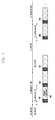
- FIG. 2 is a diagram showing a state where D2D transmission and cellular transmission are multiplexed using a Time Division Multiplexing (TDM) scheme according to an embodiment of the present invention.
- TDM Time Division Multiplexing
- reference numerals 201, 202, and 203 show that a cellular sub-frame and D2D sub-frame are time-based TDM.
- the cellular communication can be configured for the duration of the reference numeral 201 and the D2D transmission can be configured for the durations of the reference numerals 202 and 203.
- the durations of the reference numerals 202 and 203 can be referred as a discovery duration 205, and the period in which the discovery duration is generated can be referred as a discovery period 204.
- Discovery signals are multiplexed in the discovery duration 205 including one or more reference numerals 202 and 203, and also a physical uplink control channels (PUCCHs) 207 and 208 of the cellular UE may be present in the discovery duration so as to transmit a response for Hybrid Automatic Retransmit reQuest (HARQ), Scheduling Request (SR), and Channel State Information (CSI) of the forward cellular communication.
- a PUCCH such as reference numeral 207 and 208 may be present at both ends of the frequency area in the discovery duration.
- DRB Discovery Resource Block
- a DRB may be defined in a time-frequency unit of any size and may be multiplexed by forming a grid by a plurality of DRBs within the discovery duration such as reference numeral 206.
- one DRB can be defined by one sub-frame and 12 sub-carriers (one RB), the same as a PRB.
- Any UE may transmit discovery signals thereof to a single DRB in the multiplexed DRB.
- a plurality of UEs may transmit the discovery signal to the single DRB.
- the UE may determine a DRB to transmit the discovery signal of the UE based on any rule or a predetermined rule, and any UE may transmit the discovery signal using the determined DRB.
- a UE 1 transmits a discovery signal of the UE 1 using a DRB of reference numeral 211
- a UE 2 transmits a discovery signal of the UE 2 using a DRB of the reference numeral 212
- a UE 3 transmits a discovery signal of the UE 3 using a DRB of reference numeral 213
- a UE 4 transmits a discovery signal of the UE 4 using a DRM of reference numeral 214.
- the correspondence between UEs and DRB may be relatively determined.
- each UE may not receive the discovery signal from another UE. That is, the UE 1 may not receive the discovery signal from the UE 2 to UE 4, the UE 2 may not receive the discovery signal from the UE 1, UE 3, and UE 4, the UE 3 may not receive the discovery signal from the UE 1, UE 2, and UE 4, and the UE 4 may not receive the discovery signal from the UE 1 to UE 3.
- a time-frequency hopping method in which the location of the DRB varies in each discovery duration can be used.
- the positions of the DRB 1 to DRB 4 are different from the positions of the previous discovery durations, and thus the UE 1 to UE 4 may receive discovery signals from one another.
- the DRBs are differently placed in different positions in time and frequency according to the discovery duration so that any UE may receive a discovery signal of another UE in the next discovery duration, and the discovery signal of another UE may not be received in the previous discovery duration.
- a time-frequency hopping method may be determined by one or more methods among a method configured in the UE and a method including a message, etc. received from a base station.
- the UE transmits a discovery signal using one DRB, but when performing transmission in a full frequency band using any frequency block, in band other than the frequency block, a transmission power having a relative value with respect to the transmission power used in the frequency block may be generated. This is referred to as re-emission power.
- -7dBm power having, for example, 30dB difference from the transmission power of the DRB1 may be generated in a DRB other than the DRB1 211 in the same sub-frame, and the generated power may result in acting as additional noise or interference to another UE which performs signal transmission and reception in the region.
- in-band emission power will be described with reference to FIG. 3 .
- FIG. 3 is a diagram showing emission power when transmitting a signal by a UE according to the embodiment of the present invention.
- FIG. 3 shows a method for generating an in-band emission power within a full band in an embodiment.
- a diagram shows a smaller value than a value shown in the embodiment as the requirement of the in-band emission power.
- the power may have the same in-band emission power as FIG. 3 .
- the horizontal axis 301 of FIG. 3 indicates PRB index, that is a frequency axis, and the vertical axis 302 indicates a magnitude of relative transmission power.
- -30dB of transmission power is generated in the full band as shown by reference numeral 307, and to two or three PRBs near the allocated frequency, as shown by reference numeral 304, -30dB or greater transmission power may be formed, and more specifically, transmission power may be generated in two or three PRBs adjacent to the allocated frequency in a stepwise manner.
- additional emission power due to carrier leakage may be generated from at least one of PRB #24 and #25 positioned in the middle at the full band, and thus transmission power having a value greater than -30dB may be generated.
- an image frequency of the allocated frequency as shown by frequency reference numeral 306, that is, additional transmission power due to IQ imbalance may be generated in a frequency in the symmetrical position relative to the intermediate frequency and thus transmission power greater than -30dB may be generated.
- PRB #7 is an allocated frequency
- additional emission power according to the IQ imbalance may be generated in PRB #42.
- in-band emission power when any UE transmits a discovery signal using any DRB, in-band emission power may also be generated in bands other than the band to which the DRB is transmitted, due to one or more of the above factors, and may affect discovery signals of other UEs, or affect the transmission performance of a PUCCH located near the discovery signal resource to be transmitted.
- the UE 105 may transmit the PUCCH to the base station 101 using another frequency resource 2.
- the transmission loss of a signal transmitted to the base station 101 from the UE 103 may be smaller than the transmission loss of the UE 105.
- the base station 101 may receive a PUCCH signal of the UE 105 using a frequency resource 2, due to in-band emission power generated from the discovery signal transmitted by the UE 103 through a frequency resource 1 and a transmission loss difference, the reception power from the UE 103 may be greater than or similar to the PUCCH signal of the UE 105 received through the frequency resource 2. That is, the performance of the cellular UE may be deteriorated due to the D2D discovery operation.
- the transmission power control of the D2D UE may be necessary. That is, in a case where the D2D UE is relatively closer to the base station, the D2D UE allows the transmission to use less power than defined transmission power.
- the transmission power when transmitting the discovery signal by the UE may be configured as a predetermined value such as a maximum transmission power of the UE, a value defined through signaling by a wireless network including a base station, a value configured in consideration of the transmission loss with the base station, and a value configured by the combination of the above methods.
- Max_Tx_Power is the maximum available power of the transmission D2D UE
- f(D2D) is transmission power, which is determined by the service type of the discovery signal transmitted by the UE
- g (PL) is transmission power determined according to a power loss (PL) between the base station and the UE.
- Target_Rx_Power is a target value of the reception power received, by the base station, from the UE.
- the transmission power of the UE may be configured by the above equation (2) by considering an offset value in consideration of carrier leakage.
- the transmission power is configured by the base station based on a target value of the reception power received from the UE and the transmission loss between the UE and the base station, the above problems can be solved.
- a D2D UE at a closer distance with the base station may transmit a discovery signal thereof always using lower transmission power than the D2D UE which is relatively far from the base station.
- the D2D UE which is adjacent to the base station as described above always transmits the discovery signal at a low transmission power, the coverage of the discovery signal is limited. Therefore, the UEs as described above have difficulty in performing a correct D2D discovery operation.
- an embodiment of the present specification proposes a method for reducing performance degradation and deterioration of the D2D communication performance, due to in-band emission power, through the transmission power control, and increasing the overall performance, and the method will be described with reference to examples.
- Embodimen1 a periodic discovery signal transmission power control method
- D2D UEs in close proximity to the base station may transmit discovery signals thereof using lower transmission power through the power control.
- the power control method enables discovery signals thereof to be transmitted to specific D2D UEs as described above according to the position of the base station, using lower transmission power through the transmission power control for each discovery signal transmission so that D2D communication performance degradation due to the reduction of discovery signal transfer regions of the UEs may occur.
- a transmission power control operation may be performed, which is different from the transmission power control method which is periodically (T PC ) and previously used by the UEs.
- T PC is a period during which a separate power control operation is performed, which is different from the power control operation previously in use, and the previously used power control operation may be performed during the discovery signal transmission rather than the corresponding period.
- an operation of not performing transmission power for the discovery signal control may be included in the period.
- the embodiment 1 describes that transmission power for the discovery signal control is not performed during the period.
- the UE may periodically transmit a discovery signal thereof without power control for a cellular UE as the following equation (3).
- Tx_Power min Max_Tx_Power , f D 2 D
- Max_Tx_Power is the maximum available power of the transmission D2D UE
- f(D2D) is the transmission power, which is determined by the service type of the discovery signal transmitted by the UE.
- the equation (3) is only a single example in which transmission power for the discovery signal is determined by the D2D UE, and there may be various methods of determining the transmission power for the discovery signal of the D2D UE.
- the base station may perform power control using the reception power target values (Target_Rx_Power) of one or more base stations.
- a method for controlling the transmission power of the UE may be included by controlling other parameters required by the power control as well as by controlling the reception power target value of the base station.
- the base station may inform of power control information such as the base station reception power target values in the configured power control period (T PC ) and the corresponding period to the UE by using at least one of System Information Black (SIB) signaling, higher layer signaling, and dynamic signaling.
- SIB System Information Black
- the UE may be aware of the value as determined in advance.
- the power control period is an additional period for determining whether to perform an additional power control or a period used for the D2D UE such as the previously obtained period (for example, a discovery resource region re-discovery period).
- the period may be configured with the number of cellular UEs, the number of D2D UEs closer to the base station, the magnitude of a reception signal of the discovery signal transmission region measured by a base station, etc.
- a UE having acquired the period may perform power control as defined in the period, or may perform power control defined by discovery signal transmission after a constant offset (X).
- X UE_ID mod T PC
- UE_ID means a UE identification number.
- the above mentioned UE identification number is any one of possible IDs, and may include International Mobile Subscriber Identity (IMSI), Temporary Mobile Subscriber Identity (TMSI), Packet-Temporary Mobile Subscriber Identity (P-TMSI), Cell-Wireless Network Temporary Identifier (C-RNTI), and the like.
- IMSI International Mobile Subscriber Identity
- TMSI Temporary Mobile Subscriber Identity
- P-TMSI Packet-Temporary Mobile Subscriber Identity
- C-RNTI Cell-Wireless Network Temporary Identifier
- the offset value may be determined by using other information having a UE-specific value as well as the UE identification number.
- FIG. 4 is a diagram for explaining an operation of performing power control by a UE according to a discovery signal transmission power control period.
- the UE 1 and UE 2 which acquire the power control period (TPC) from the base station perform a power control operation according to the period, perform a previously used power control operation for discovery signal transmission during discovery signal transmission durations 401, 402, 403, 404, and 405, and performs, during a period corresponding to T PC , a power control operation defined in the period.
- TPC power control period
- both UE 1 and UE 2 which have reached a power control period (T PC ) during the duration 401 may transmit a discovery signal thereof without power control.
- the UE 1 transmits a discovery signal after performing a previously used power control operation by the offset value of the UE-specific in the duration 401 and does not perform the power control in the duration 402.
- the UE 2 in the durations 401 and 402, transmits a discovery signal after performing a previously used power control operation as the operation in the duration 401 of the UE, and, in the duration 403, transmits the discovery signal without performing power control.
- D2D UEs closer to the base station may also transmit discovery signals thereof without considering a cellular UE during a particular discovery signal duration through embodiment 1, D2D performance degradation depending on the position of the UE can be prevented. Further, by dispersing the D2D UEs which perform power control using the T PC and the offset value as described above, in-band emission power effects on the cellular UE can be minimized.
- each UE may or may not perform power control in the corresponding period based on a power control performing period offset value. More specifically, it is possible to perform the control for reducing the transmission power in the conventional discovery signal transmission duration. In addition, a control for increasing the transmission power in the discovery signal transmission duration, during the time duration corresponding to the power control performing period offset value, may be performed, and in accordance with an embodiment, a control for reducing the transmission power in the discovery signal transmission duration, during the time duration corresponding to the power control performing period offset value, may not be performed.
- D2D UEs in close proximity to the base station may transmit discovery signals thereof using lower transmission power through the power control.
- the above power control method enables discovery signals thereof to be transmitted to the specific D2D UEs according to the position of the base station, using lower transmission power through the transmission power control for each discovery signal transmission so that D2D communication performance degradation due to the reduction of discovery signal transfer region of the UEs may occur.
- the base station allocates a duration in which power control is not performed for the discovery signal transmission in some resource regions among the D2D discovery signal resource regions.
- the base station separates the discovery signal resource region into one or more duration different each other and being operated so as to perform different power control for each duration to solve the above problem.
- the base station separates D2D resource regions by using one or more target received powers, or a signal-to-interference plus noise ratio requirement, and enables the UE to perform different transmission power control operations for each resource region to solve the problem.
- the UE may transmit discovery signal thereof using the D2D resource region allocated for D2D communication by the base station, and receive discovery signals transmitted by adjacent UEs. At this time, the UE may select any one or a plurality of resources among the D2D resource region and transmit a discovery signal thereof. On the other hand, the UE may measure the reception signal strength of all of the D2D resources or some of the D2D resource regions, select a resource having the lowest signal strength and transmit the discovery signal thereof, and select any one among a resource candidate groups having low reception signal strength.
- a UE for transmitting a discovery signal may transmit the discovery signal in time or may not receive the discovery signal from the another UE in time. Therefore, the UE may select any resource for each discovery signal transmission period or select a different discovery resource for each discovery signal transmission period using a predefined pattern (e.g., time-frequency hopping) to transmit the discovery signal.
- a predefined pattern e.g., time-frequency hopping
- the UE may use different discovery signal resources for each discovery signal transmission period so that the above problem can be addressed. That is, when the base station separates the D2D discovery signal resource regions into one or more regions, and enables each of the UEs to perform different power control operations in each region, the UEs may perform a different power control operation for each discovery signal transmission period.
- the D2D discovery resource region configured by one or more sub-frames may be separated into one or more sub-frame sets, and a different transmission power control method for each sub-frame set may be used.
- the base station may use the reception signal strength requirement or the signal-to-interference-noise ratio requirement received from the UE to perform different power control operations for each sub-frame.
- not performing a separate power control operation for the cellular UE may be a method for a power control operation.
- the UE may perform a discovery signal transmission power control operation according to the power control corresponding to a discovery resource region determined for each discovery signal transmission period.
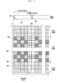
- FIG. 5 is a diagram for explaining a power control operation by a UE for a discovery resource region separated according to two transmission power control methods which are different from each other.
- the base station may perform one or more different power controls on resource regions of reference numerals 502 and 503, for example, by separating a D2D discovery signal transmission area 501.
- reference numeral 502 is a region for performing, by the UE, the discovery signal transmission power control operation for the cellular UE
- reference numeral 503 is a region for not performing, by the UE, the discovery signal transmission power control operation for a cellular UE.
- reference numeral 503 may include at least one of no power control and performing a power control operation different from the reference numeral 502.
- the discovery resource area division according to the power control is to distinguish the performance of one or more different power control operations by the UE, and no power control is also a part of the power control operation.
- the discovery signal of the UE is transmitted according to the transmission power control method of the power control region 502.
- the UE uses the region of the reference numeral 505 as its own discovery signal transmission resource, the discovery signal of the UE is transmitted according to the transmission power control method of the power control region 503.
- the UE when not performing transmission power control for the cellular UE in the region 503, the UE may transmit a discovery signal without performing a separate transmission power control operation for the cellular UE.
- the transmitting of the discovery signal by the UE without performing a separate transmission power control operation may include transmitting the discovery signal by the UE with a maximum transmission power or power close thereto.
- a D2D UE adjacent to the base station when the region for performing power control as shown in the region 502 of FIG. 5 is to be selected for discovery signal transmission resource, a D2D UE adjacent to the base station, according to a discovery signal resource region-specific transmission power control method by the base station, may perform power control in order to minimize interference to a PUCCH region 506 of the UE for performing cellular communication, and when there is no power control region as shown in the region 503 of FIG. 5 , may transmit a signal while performing power control for the PUCCH.
- the D2D UE adjacent to the base station is not always performing power control, the discovery signal performance degradation of the D2D UE can be reduced.
- the cellular UE may be aware that the performance of the cellular UE will be degraded in the resource region 507 in which a control signal is transmitted by the cellular UE. Therefore, the base station may control the cellular UE so as not to use the region or minimally use the region through the scheduling and resource allocation, etc. That is, the base station may configure the operation of the cellular UEs on the regions by using information on the performance difference between the cellular UEs in the regions of reference numerals 506 and 507.
- the power control information for each discovery signal resource region and a corresponding region may be informed of to the UE, by the base station, through a System Information Block (SIB), or the downlink control channel, higher layer signaling, and dynamic signaling.
- SIB System Information Block
- the UEs may be aware of the information as a value determined in advance.
- the information may include position (for example, time, frequency) information on the divided discovery signal resource duration and information and power control-related parameters for each duration.
- D2D UEs in close proximity to the base station may transmit discovery signals thereof using lower transmission power through the power control.
- the above power control method enables discovery signals thereof to be transmitted to the specific D2D UEs according to the position of the base station, using lower transmission power through the transmission power control for each discovery signal transmission so that D2D communication performance degradation due to the reduction of discovery signal transfer region of the UEs may occur.
- the base station may divide the D2D discovery resource region into one or more regions based on a predetermined criteria (e.g., based on a reception power of the discovery signal from the base station or based on the position of a UE) and the D2D discovery resource region can be divided into one or more regions.
- the UE enables the discovery signal thereof to be transmitted within the discovery signal region corresponding to the UE from among the reference regions configured by the base station so that the problem can be solved.
- the base station may measure reception power for the discovery signal received from the D2D UE and divide the D2D discovery resource into one or more regions. For example, the base station may divide the D2D discovery resource into two regions based on reception power XdBm for the discovery signals of the D2D UEs received by the base station.
- a reference may be configured by one of various measurement values including a transmission path loss value between the base station and the UE, Signal-to-Noise Ratio (SNR) or Signal-to-Interference plus Noise Ratio (SINR) as well as reception signal strength of the base station.
- a reference value may be configured as a value capable of minimizing the PUCCH performance deterioration of the cellular UE including the discovery signal transmission by the D2D UE.
- the reception power for discovery signals by D2D UEs of the base station may be used as the basis for the position of the D2D UE. That is, when the base station notifies a reference of the reception power from the D2D UEs to other UEs, the other UEs may predict the reception power of the base station on the discovery signal transmission by the UE, using a path loss value with the base station and the discovery signal transmission power. That is, since the base station adjacent to the UE has a relatively small path loss value, it is difficult to satisfy a requirement of the base station. In other words, reception power of the discovery signals of the D2D UEs may be interpreted as reference values for the location of the UEs. The requirement may be determined based on the magnitude of the reception power measured when the discovery signal transmitted by the UE is received at the base station.
- the reference value and the area for the control information may be notified of to the UE by the base station through the System Information Block (SIB), the downlink control channel, the higher layer signaling, or the dynamic signaling.
- SIB System Information Block
- the UEs may be aware of the information as a value determined in advance.
- the information may include position (e.g., time and frequency) information on the divided discovery signal resource duration.
- the UE which has acquired the reference value may predict the magnitude of the discovery signal thereof received at the base station, by using the measured channel value such as path loss information between the base station and the UE, and a transmission power value of the discovery signal. Therefore, the UE may compare the information with reference information configured by the base station to know its own discovery signal transmittable region.
- the UE having acquired the discovery signal transmittable region may select its own discovery signal from among one or more regions which transmits the discovery signal. At this time, the UE may select any one resource or a plurality of resources among the discovery signal transmittable region and transmit the discovery signal of the UE. On the other hand, the UE may measure the reception signal strength of all of the D2D resources or some of the D2D resource region, select a resource having the lowest signal strength and transmit the discovery signal thereof, and select any one among a resource candidate group having low reception signal strength. However, in some cases, a UE for transmitting a discovery signal according to an embodiment may not transmit the discovery signal or may not receive the discovery signal from the other UE in time.
- the UE may select any resource for each discovery signal transmission period, or select discovery resources different from each other among the discovery signal transmittable region for each discovery signal transmission period using a predefined pattern (e.g., time-frequency hopping) to transmit the discovery signal.
- a predefined pattern e.g., time-frequency hopping
- the time-frequency hopping pattern may be formed according to the same discovery signal transmitted area.
- the base station operates the D2D discovery resource region by dividing the discovery signal transmittable area using a predetermined reference so that the base station may predict an influence from the D2D UE.
- the D2D discovery resource region configured by one or more sub-frames may be divided into one or more sub-frames set so that D2D UEs adjacent to the base station and D2D UEs far from the base station may transmit a discovery signal in the sub-frames set different from each other. Therefore, the base station may know in advance the information that the performance of the cellular UE will be degraded due to the interference caused by the discovery signal, in the resource region of a sub-frame set for transmitting the discovery signal by the D2D UE close to the base station.
- the base station may control the cellular UE so as not to use the region or minimally use the region through the scheduling and resource allocation, etc. That is, the base station may configure the operation of the cellular UEs on the regions by using information on the performance difference between the cellular UEs in the regions divided by the reference.
- FIG. 6 is a diagram for explaining a power control operation by a UE for a discovery resource region which is divided based on the position of a UE.
- the base station may divide the D2D discovery signal transmission area 601 based on the reference on the position of one or more UEs, such as regions 602 and 603.
- the reference numeral 602 is a region for performing the discovery signal transmission by a UE of which a distance between the base station and the UE is farther than the reference point
- the reference numeral 603 is a region for performing the discovery signal transmission by a UE of which a distance between the base station and the UE is closer than the reference point.
- the discovery resource region is divided based on the location of the UE for convenience of explanation, however information capable being received or measured from the UE by the base station, such as the discovery signal strength of a D2D UE received from the base station, can be used as a reference or measured.
- a distance between the base station and the UE may be determined based on a channel state between the base station and the UE.
- a UE which determines that a distance from the base station is farther than a configured reference point, selects a discovery signal transmission resource thereof in a remaining region 602 except for a region indicated by reference numeral 603. For example, the UE selects a region of the reference numeral 604 within the region of reference numeral 602 and transmits the discovery signal thereof. However, a UE, which determines that a distance from the base station is closer than a configured reference point, selects discovery signal transmission resource thereof in a remaining region 603 except for a region indicated by reference numeral 602. For example, the UE selects a region of the reference numeral 605 within the region of reference numeral 603 and transmits the discovery signal thereof.
- the UE when performing the discovery signal transmission using a pre-defined pattern (time-frequency hopping), the UE, which has performed the discovery signal transmission in one region among the region 602 of the D2D discovery signal transmission duration 601, may be defined so as to select one of the discovery signal regions corresponding to the reference, such as 602, in a D2D discovery signal transmission duration 608.
- the UE, which has performed the discovery signal transmission in one region among the region 603 of the D2D discovery signal transmission duration 601 should be defined so as to select one of the discovery signal regions corresponding to the reference, such as 603, in the D2D discovery signal transmission duration 608.
- the time-frequency hopping pattern may be defined such that one of the discovery signal resources within the same divided region is selected for each D2D discovery signal transmission duration.
- the base station since only the D2D UEs, which are farther from the base station according to the reference point configured by the base station, may transmit the discovery signal in the region 602, the impact on a PUCCH region 606 of the UE for performing the cellular communication can be minimized.
- D2D UEs relatively closer to the base station in the duration such as the region 603, may transmit the discovery signal, the performance of a PUCCH region 607 of the UE for performing the cellular communication can be degraded.
- the base station may know in advance the information that the performance of the cellular UE in the region 607 will be degraded according to the reference point configuration. Therefore, the base station may control the cellular UE so as not to use the region or minimally use the region through the scheduling and resource allocation, etc. so that the impact on the cellular UE can be minimized.
- D2D UEs in close proximity to the base station may transmit discovery signals thereof using transmission power lower than the maximum transmitted power through the power control.
- the power control method as described above allows discovery signals to be transmitted to specific D2D UEs according to the position of the base station, using lower transmission power for each discovery signal transmission through the transmission power control so that D2D communication performance degradation of the UEs may occur.
- the base station may notify of discovery signal transmission power control information in each D2D sub-frame, using a downlink control channel to the UE.
- the base station may solve the problem by being able to dynamically control the transmission power for the discovery signal of the D2D UE area according to the PUCCH transmission of a cellular UE.
- the base station may configure, in each discovery signal transmission area, transmission power control information on discovery signal transmission areas of the D2D UEs according to the information on the cellular UE. That is, when there is no PUCCH transmission by the cellular UE in some of the sub-frame among the discovery signal transmission area, at that time, the base station UE may notify using a downlink control channel that the D2D UE may transmit a discovery signal using a transmittable power without considering the cellular UE.
- the base station may control the discovery signal transmission power of the D2D UE to minimize the impact on the cellular UE.
- the base station may configure transmission power control information for the discovery signal transmission area to the UE, using a downlink control channel such as a new Downlink Control Information (DCI) format for the D2D.
- DCI Downlink Control Information
- the DCI format may include other information for D2D UEs such as the information on the discovery signals of the D2D UEs as well as the discovery signal transmission power control information.
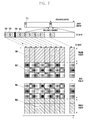
- FIG. 7 is a diagram explaining an operation of controlling, by a base station, a discovery signal transmission power of a UE for downlink control channel information.
- a D2D discovery signal transmission area 701 of the base station may include a plurality of sub-frames.
- a sub-frame may be formed of a control signal transmission section 702 and a data signal transmission section 703. Therefore, the base station may control the transmission power of the D2D UE through transmitting a control signal in each sub-frame of the area 701.
- the base station enables the UE to perform a power control on the sub-frame without considering the cellular UE through control signal transmission of the reference numeral 702.
- the UE may select a discovery resource in a reference numeral 707 region and transmit the discovery signal without a separate power control for the cellular UE.
- the base station enables the UE to perform power control in consideration of the cellular UE in the sub-frame through control signal transmission of the reference numeral 704. Therefore, the UE may select a discovery resource in a reference numeral 708 region and transmit the discovery signal after performing a power control operation for the cellular UE.
- control information signal may include additional information (for example, discovery signal transmission resource area) on the discovery signal transmission, including a configuration value for the power control of the D2D UE.
- the D2D UE may control discovery signal power according to the configuration of the discovery signal power control of the base station, the impact on the PUCCH regions 706 and 709 of the UE for performing cellular communication can be minimized.
- the discovery signal can be transmitted without any additional power control according to the power control setting for the base station, a problem of the performance deterioration due to the power control operation for a cellular UE can be solved.
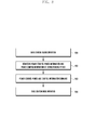
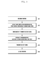
- FIG. 8 is a flow chart illustrating an operation of a base station according to a first embodiment of the present invention.
- step 801 the base station begins an operation.
- the base station may set power control period information and power control information on the period.
- the power control period information may include at least one of a period value for performing power control and offset information.
- the power control information may include a value that is the basis for controlling transmission power for transmitting a discovery signal by the UE.
- the base station may signal, to the UE, the configured power control period and power control information. More specifically, the base station may signal the configured power period information through at least one of SIB signaling, RRC signaling, and dynamic signaling to the UE.
- step 804 the base station ends the operation.
- FIG. 9 is a flow chart illustrating an operation of a UE according to a first embodiment of the present invention.
- step 901 the UE begins an operation.
- the UE may receive a power control period and power control information on the period from a base station.
- Step 902 may be selectively performed according to an embodiment, and when the step 902 is not performed, the UE may use the configured information without receiving the power control information from the base station.
- the UE configures a DRB for transmitting a discovery signal thereof in any discovery duration.
- the DRB configuration may be determined according to the DRB position determined by the UE or the base station, and the position of each transmission DRB may be different depending on the application of the frequency hopping.
- the UE sets a power control period offset according to the configured DRB and power control period and sets a reference power by using the power control information in the period.
- the power control period offset information may be determined according to information received in step 902 or a preconfigured UE information.
- step 905 the UE performs a discovery signal transmission by using the configured transmission power.
- step 906 the UE ends the operation.
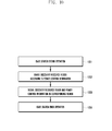
- FIG. 10 is a flow chart illustrating an operation of a base station according to a second embodiment of the present invention.
- step 1001 the base station begins an operation.
- the base station may divide and configure the discovery resource region according to the power control information.
- the base station may signal, to the UE, at least one of information on the configured discovery resource region and power control information on the region. More specifically, the base station may signal, to the UE, the configured power control information through at least one of SIB signaling, RRC signaling, and dynamic signaling.
- step 1004 the base station ends the operation.
- FIG. 11 is a flow chart illustrating an operation of a UE according to a second embodiment of the present invention.
- step 1101 the UE begins an operation.
- the UE may receive discovery resource region information and power control information for each region from the base station.
- the discovery resource region information includes discovery resource transmission region information having different power control information performed therein.
- the power control information may include the power control information performed in each discovery resource transmission region.
- Step 1102 may be selectively performed according to an embodiment, and when the step 1102 is not performed, the UE may use the configured information without receiving the power control information from the base station.
- the UE configures a DRB for transmitting a discovery signal thereof in a discovery duration region.
- the DRB configuration may be determined according to the DRB position determined by the UE or the base station, and the position of each transmission DRB may be different depending on the application of the frequency hopping.
- step 1104 the UE sets the transmission power using the power control information according to the configured DRB region.
- step 1105 the UE performs a discovery signal transmission by using the configured transmission power.
- step 1106 the UE ends the operation.
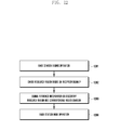
- FIG. 12 is a flow chart illustrating an operation of a base station according to a third embodiment of the present invention.
- step 1201 the base station begins an operation.
- the base station may divide a discovery resource region according to a reference of a reception signal or a reference on a UE position, and configure a discovery resource transmission region.
- the UE location may be determined based on one or more of the magnitude of the reception power for receiving a signal transmitted by the UE, path loss, and an SINR value.
- the base station may signal, to the UE, the configured discovery resource region information and region dividing reference information. More particularly, the base station may signal to the UE through at least one among SIB signaling, RRC signaling, and dynamic signaling.
- the region dividing reference information according to an embodiment may include a basis for selecting, by the UE, the discovery signal transmission region resource for a specific region according to the embodiment.
- step 1204 the base station ends the operation.
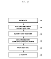
- FIG. 13 is a flow chart illustrating an operation of a UE according to a third embodiment of the present invention.
- step 1301 the UE begins an operation.
- the UE may receive a discovery resource region and the region dividing reference information from the base station.
- the step 1302 may be selectively performed according to an embodiment, and when the step 1302 is not performed, the UE may use pre-configured information.
- the reference information for dividing the region according to an embodiment may include a basis for selecting, by the UE, the discovery signal transmission region resource for a specific region according to the embodiment.
- step 1303 the UE selects a discovery signal transmittable area thereof based on the received reference signal region.
- the UE configures a DRB for transmitting a discovery signal thereof among the discovery signal transmittable region.
- the configuration of the DRB may be determined according to the determination of the DRM position by the UE or the base station, the position of each transmission DRB may be different depending on the application of the time-frequency hopping, but at this time, the time-frequency hopping is performed within the discovery signal transmission region selected in step 1303.
- step 1305 the UE transmits the discovery signal by using the configured DRB region.
- step 1306 the UE ends the operation.
- FIG. 14 is a flow chart illustrating an operation of a base station according to a fourth embodiment of the present invention.
- step 1401 the base station begins an operation.
- the base station may configure the power control information for the D2D signal transmission region according to the cellular UE.
- the D2D UE may configure power control information for the discovery signal region determined based on the influence of a cellular UE in the UE, according to the discovery signal in the resource region for transmitting the discovery signal.
- the power control information for the discovery signal region may include at least one of a method for controlling transmission power and a value of the transmission power in a specific resource region.
- the base station signals the configured discovery resource region and power control information on the region to the UE.
- step 1404 the base station ends the operation.
- FIG. 15 is a flow chart illustrating an operation of a UE according to a fourth embodiment of the present invention.
- step 1501 the UE begins an operation.
- the UE receives power control information on a discovery resource region from the base station.
- the power control information for the discovery signal region may include at least one of a method for controlling transmission power and a value of the transmission power in a specific resource region.
- the step 1502 may be selectively performed according to an embodiment, and when the step 1502 is not performed, the UE may use pre-configured information.
- the UE configures a DRB for transmitting a discovery signal thereof among a discovery signal transmittable region.
- the DRB configuration may be determined according to the DRB position determined by the UE or base station, and the position of each transmission DRB may be different depending on the application of the time-frequency hopping.
- step 1504 the UE sets transmission power for the discovery signal according to the received power control information.
- step 1505 the UE transmits the discovery signal by using the configured DRB region and transmission power.
- step 1506 the UE ends the operation.
- FIG. 16 is a diagram showing a configuration of a base station according to an embodiment of the present invention.
- FIG. 16 is a block diagram illustrating an internal configuration of a base station according to an embodiment of the present invention.
- the base station of the present invention may include a transceiver 1601 and controller 1602.
- the transceiver 1601 transmits and receives a signal to and from nodes of a wireless communication system through a wired or wireless interface.
- the transceiver 1601 may transmit and receive control information or data to and from a UE through the wireless interface.
- the controller 1602 controls the signal flow between blocks for the operation of the base station.
- the controller 1602 may control the sequence of operations for controlling transmission power for the discovery signal of the UE performing the D2D communication.
- the controller 1602 may further include a base station-related information management unit 1603.
- the base station-related information management unit 1603 may control to transmit, to the UE, the base station-related information necessary for controlling transmission power for the discovery signal of the UE performing the D2D communication. According to each embodiment of the present invention, the base station-related information management unit 1603 may control to transmit, to the UE, additional transmission power control information on the discovery signal region division and each region according to the position of DRB.
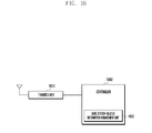
- FIG. 17 is a block diagram illustrating an internal structure of a UE according to an embodiment of the present invention.
- a UE of the present invention may include a transceiver 1701 and controller 1702.
- the transceiver 1701 transmits and receives signals to and from a base station through a wireless interface. According to an embodiment of the invention, the transceiver 1701 may receive D2D-related information of the serving base station.
- the controller 1702 controls the signal flow between blocks for the operation of the base station.
- the controller 1702 may select a discovery signal for performing D2D communication based on the D2D information received from the serving base station and control the transmission power of the selected discovery signal.
- the controller 1702 may further include a resource selection unit 1703 and a power controller 1704.
- a resource selection unit 1703 may receive information on the DRB region from the base station, and select a transmission resource of the discovery signal for performing D2D communication on the basis of the received information. Since the specific process for selecting a resource of the discovery signal is mentioned above, a detailed description thereof will be omitted.
- the power controller 1704 may receive power control information according to the DRB region from the base station, and control transmission power of the discovery signal for performing D2D communication on the basis of the received information. Since the specific process for controlling a transmission power of the discovery signal is mentioned above, a detailed description thereof will be omitted.
Landscapes
- Engineering & Computer Science (AREA)
- Signal Processing (AREA)
- Computer Networks & Wireless Communication (AREA)
- Databases & Information Systems (AREA)
- Mobile Radio Communication Systems (AREA)
Priority Applications (1)
| Application Number | Priority Date | Filing Date | Title |
|---|---|---|---|
| EP19213244.7A EP3637921B1 (fr) | 2013-10-08 | 2014-10-06 | Procédé et appareil de multiplexage de commande de puissance de signal d'émission et de ressource de signal de découverte dans un système de communication sans fil |
Applications Claiming Priority (2)
| Application Number | Priority Date | Filing Date | Title |
|---|---|---|---|
| KR1020130120103A KR102236020B1 (ko) | 2013-10-08 | 2013-10-08 | 무선 통신 시스템의 전송 신호 전력 제어 및 발견 신호 자원 다중화 방법 및 장치 |
| PCT/KR2014/009367 WO2015053514A1 (fr) | 2013-10-08 | 2014-10-06 | Procédé et appareil de multiplexage de commande de puissance de signal d'émission et de ressource de signal de découverte dans un système de communication sans fil |
Related Child Applications (2)
| Application Number | Title | Priority Date | Filing Date |
|---|---|---|---|
| EP19213244.7A Division-Into EP3637921B1 (fr) | 2013-10-08 | 2014-10-06 | Procédé et appareil de multiplexage de commande de puissance de signal d'émission et de ressource de signal de découverte dans un système de communication sans fil |
| EP19213244.7A Division EP3637921B1 (fr) | 2013-10-08 | 2014-10-06 | Procédé et appareil de multiplexage de commande de puissance de signal d'émission et de ressource de signal de découverte dans un système de communication sans fil |
Publications (3)
| Publication Number | Publication Date |
|---|---|
| EP3057367A1 true EP3057367A1 (fr) | 2016-08-17 |
| EP3057367A4 EP3057367A4 (fr) | 2017-05-24 |
| EP3057367B1 EP3057367B1 (fr) | 2020-02-19 |
Family
ID=52813292
Family Applications (2)
| Application Number | Title | Priority Date | Filing Date |
|---|---|---|---|
| EP19213244.7A Active EP3637921B1 (fr) | 2013-10-08 | 2014-10-06 | Procédé et appareil de multiplexage de commande de puissance de signal d'émission et de ressource de signal de découverte dans un système de communication sans fil |
| EP14852036.4A Active EP3057367B1 (fr) | 2013-10-08 | 2014-10-06 | Procédé et appareil de multiplexage de commande de puissance de signal d'émission et de ressource de signal de découverte dans un système de communication sans fil |
Family Applications Before (1)
| Application Number | Title | Priority Date | Filing Date |
|---|---|---|---|
| EP19213244.7A Active EP3637921B1 (fr) | 2013-10-08 | 2014-10-06 | Procédé et appareil de multiplexage de commande de puissance de signal d'émission et de ressource de signal de découverte dans un système de communication sans fil |
Country Status (7)
| Country | Link |
|---|---|
| US (2) | US10506521B2 (fr) |
| EP (2) | EP3637921B1 (fr) |
| JP (1) | JP6406589B2 (fr) |
| KR (1) | KR102236020B1 (fr) |
| CN (2) | CN105637963B (fr) |
| AU (1) | AU2014332694B2 (fr) |
| WO (1) | WO2015053514A1 (fr) |
Families Citing this family (16)
| Publication number | Priority date | Publication date | Assignee | Title |
|---|---|---|---|---|
| JP6197109B2 (ja) * | 2013-10-03 | 2017-09-13 | エルジー エレクトロニクス インコーポレイティド | 無線通信システムにおけるd2d動作のための資源を使用する方法及び装置 |
| US10206215B2 (en) * | 2014-03-11 | 2019-02-12 | Lg Electronics Inc. | Method for assigning resources in wireless communication system supporting device-to-device direct communication, and apparatus therefor |
| WO2016087497A1 (fr) * | 2014-12-02 | 2016-06-09 | Telefonaktiebolaget Lm Ericsson (Publ) | Commande de puissance combinée pour communication sans fil d2d |
| US10455481B2 (en) * | 2015-05-08 | 2019-10-22 | Lg Electronics Inc. | Method and device for transmitting and receiving discovery signal of device-to-device communication terminal in wireless communication system |
| WO2017014555A1 (fr) * | 2015-07-20 | 2017-01-26 | 엘지전자 주식회사 | Procédé d'attribution de ressources pour une communication de dispositif à dispositif dans un système de communication sans fil, et appareil correspondant |
| KR101662505B1 (ko) * | 2015-07-27 | 2016-10-05 | 경상대학교산학협력단 | 단말간 통신 시스템에서 전송 전력을 결정하는 장치 및 방법 |
| US10244482B2 (en) | 2015-08-21 | 2019-03-26 | Lg Electronics Inc. | Method for transmitting or receiving V2X signal in wireless communication system and device for performing same |
| US10462803B2 (en) * | 2015-09-25 | 2019-10-29 | Telefonaktiebolaget Lm Ericsson (Publ) | Control signaling for device to device communication |
| KR102426304B1 (ko) * | 2016-07-28 | 2022-07-27 | 엘지전자 주식회사 | 무선 통신 시스템에서 플래툰 통신에 관련된 신호 송수신 방법 |
| CN109644393B (zh) * | 2016-09-29 | 2020-10-27 | 华为技术有限公司 | 一种数据发送方法和装置 |
| US9986513B1 (en) * | 2016-12-31 | 2018-05-29 | Sprint Communications Company L.P. | Device to-device (D2D) transmission power control |
| KR102398842B1 (ko) * | 2017-03-23 | 2022-05-17 | 삼성전자 주식회사 | 무선 통신 시스템에서 무선 경로 변경 방법 및 장치 |
| WO2019027273A1 (fr) * | 2017-08-03 | 2019-02-07 | 엘지전자 주식회사 | Procédé de commande de puissance de transmission dans un système de communication sans fil, et appareil correspondant |
| US11025296B2 (en) * | 2018-01-30 | 2021-06-01 | Qualcomm Incorporated | Nested frequency hopping for data transmission |
| US11337167B2 (en) * | 2018-09-28 | 2022-05-17 | Lg Electronics Inc. | Method for transmitting or receiving signal in wireless communication system and apparatus supporting same |
| US11678276B2 (en) * | 2021-07-29 | 2023-06-13 | Qualcomm Incorporated | Automatic gain control for co-existence of slot-based and sub-slot-based physical sidelink shared channels |
Family Cites Families (66)
| Publication number | Priority date | Publication date | Assignee | Title |
|---|---|---|---|---|
| US6308637B1 (en) * | 1999-10-18 | 2001-10-30 | Rapid Industries, Inc. | Pivotal pusher dog for overhead I-beam conveyor system |
| US7519032B2 (en) * | 2002-09-04 | 2009-04-14 | Koninklijke Philips Electronics N.V. | Apparatus and method for providing QoS service schedule and bandwidth allocation to a wireless station |
| US7995583B2 (en) * | 2002-09-10 | 2011-08-09 | Koninklijke Philips Electronics N.V. | Apparatus and method for announcing a pending QoS service schedule to a wireless station |
| AU2003271107A1 (en) * | 2002-10-23 | 2004-05-13 | Sharp Kabushiki Kaisha | Communication management method, central control station, communication station, communication management program, and computer-readable recording medium storing communication management program |
| US20050108385A1 (en) * | 2003-10-28 | 2005-05-19 | Gabriel Wechter | Method and system for managing a discovery-related process in a network |
| CN1735224A (zh) * | 2004-08-10 | 2006-02-15 | 皇家飞利浦电子股份有限公司 | 用于限制p2p通信干扰的方法和装置 |
| US7610225B2 (en) * | 2004-08-13 | 2009-10-27 | Qualcomm Incorporated | Methods and apparatus for performing resource tracking and accounting at a mobile node |
| US7616746B2 (en) * | 2004-08-13 | 2009-11-10 | Qualcomm Incorporated | Methods and apparatus for tracking and charging for communications resource reallocation |
| US7664091B2 (en) * | 2005-10-03 | 2010-02-16 | Motorola, Inc. | Method and apparatus for control channel transmission and reception |
| EP1977563B1 (fr) * | 2006-01-11 | 2018-01-03 | QUALCOMM Incorporated | Codage de signaux de balise pour l'identification dans une communication de pair a pair |
| EP3048849B1 (fr) * | 2006-03-07 | 2017-06-21 | Panasonic Corporation | Réduction de surcharge de signalisation de contrôle de liaison montante dans un système de communication mobile |
| PL3223566T3 (pl) * | 2008-03-19 | 2020-09-21 | Telefonaktiebolaget Lm Ericsson (Publ) | Ulepszone harmonogramowanie łącza w górę w systemie komórkowym |
| US9072060B2 (en) * | 2008-06-03 | 2015-06-30 | Nokia Technologies Oy | Method, apparatus and computer program for power control to mitigate interference |
| US8554200B2 (en) * | 2008-09-12 | 2013-10-08 | Nokia Corporation | Method and apparatus for providing interference measurements for device to-device communication |
| US8311053B2 (en) * | 2008-09-15 | 2012-11-13 | Infineon Technologies Ag | Methods for controlling an uplink signal transmission power and communication devices |
| KR101605346B1 (ko) * | 2009-01-23 | 2016-03-23 | 삼성전자주식회사 | 펨토 셀에서 단말기의 전력 제어 방법 및 장치 |
| US8897266B2 (en) * | 2009-03-27 | 2014-11-25 | Qualcomm Incorporated | Method and apparatus for transmitting control information via upper layer |
| US9351340B2 (en) * | 2009-04-08 | 2016-05-24 | Nokia Technologies Oy | Apparatus and method for mode selection for device-to-device communications |
| US8938247B2 (en) * | 2009-04-23 | 2015-01-20 | Qualcomm Incorporated | Sounding reference signal for coordinated multi-point operation |
| US9585108B2 (en) * | 2009-05-04 | 2017-02-28 | Qualcomm Incorporated | Method and apparatus for uplink power control in a multicarrier wireless communication system |
| US8331965B2 (en) * | 2009-06-12 | 2012-12-11 | Qualcomm Incorporated | Methods and apparatus for controlling resource use in a wireless communications system |
| JP5020300B2 (ja) * | 2009-10-28 | 2012-09-05 | シャープ株式会社 | 無線通信システム、移動局装置、基地局装置、無線通信方法および移動局装置の制御プログラム |
| US9247411B2 (en) * | 2009-12-23 | 2016-01-26 | Qualcomm Incorporated | Methods and apparatus for supporting multi-hop peer discovery in peer-to-peer wireless networks |
| JP4981929B2 (ja) * | 2010-01-08 | 2012-07-25 | シャープ株式会社 | 無線通信システム、移動局装置、基地局装置、無線通信方法および集積回路 |
| US8504052B2 (en) | 2010-05-06 | 2013-08-06 | Nokia Corporation | Measurements and fast power adjustments in D2D communications |
| JP5588236B2 (ja) * | 2010-06-21 | 2014-09-10 | 株式会社Nttドコモ | 送信電力制御方法、移動端末装置及び無線基地局装置 |
| US10517098B2 (en) * | 2010-07-30 | 2019-12-24 | Qualcomm Incorporated | Interference coordination for peer-to-peer (P2P) communication and wide area network (WAN) communication |
| CN103190196B (zh) | 2010-10-13 | 2015-12-09 | 诺基亚公司 | 通信模式的选择 |
| US20130201954A1 (en) * | 2010-10-14 | 2013-08-08 | Keilalahdentie 4 | Device to Device and Connection Mode Switching |
| US9014062B2 (en) | 2010-12-27 | 2015-04-21 | Electronics And Telecommunications Research Institute | Method for HARQ and link adaptation of device to device link in direct communication between user equipments and relaying by user equipment |
| WO2012109725A2 (fr) * | 2011-02-17 | 2012-08-23 | Research In Motion Limited | Optimisation de retard de paquet dans la liaison montante d'un réseau sans fil à relais coopératif activé, à plusieurs bonds |
| CN102740433B (zh) * | 2011-04-02 | 2017-06-13 | 中兴通讯股份有限公司 | 一种物理上行控制信道的功率控制方法和装置 |
| US8724492B2 (en) * | 2011-04-08 | 2014-05-13 | Motorola Mobility Llc | Method and apparatus for multi-radio coexistence on adjacent frequency bands |
| US9288773B2 (en) | 2011-04-22 | 2016-03-15 | Qualcomm Incorporated | Methods and apparatus for controlling interference from peer discovery in WWAN |
| EP2715981B1 (fr) * | 2011-06-01 | 2018-11-28 | NTT DoCoMo, Inc. | Accès local amélioré dans des communications mobiles |
| US9237434B2 (en) * | 2011-07-13 | 2016-01-12 | Qualcomm Incorporated | Network-assisted peer discovery with network coding |
| KR101258158B1 (ko) * | 2011-08-02 | 2013-04-25 | 성균관대학교산학협력단 | D2d통신 단말의 전력 제어 방법 및 d2d통신 세션 개설 방법 |
| EP2756623B1 (fr) * | 2011-09-12 | 2018-04-04 | Ntt Docomo, Inc. | Accès local amélioré dans des communications mobiles avec allocation de ressources fdd |
| GB2497916B (en) * | 2011-11-11 | 2014-06-25 | Broadcom Corp | Methods, apparatus and computer programs for monitoring for discovery signals |
| WO2013073899A1 (fr) * | 2011-11-16 | 2013-05-23 | 엘지전자 주식회사 | Procédé et appareil de détection de canal de commande dans système de communication sans fil |
| GB2497752B (en) * | 2011-12-19 | 2014-08-06 | Broadcom Corp | Apparatus and methods for supporting device-to-device discovery in cellular communications |
| WO2013103219A1 (fr) * | 2012-01-03 | 2013-07-11 | 엘지전자 주식회사 | Procédé de réglage de puissance d'émission de liaison descendante dans un système d'accès sans fil, et appareil correspondant |
| GB2498713A (en) * | 2012-01-18 | 2013-07-31 | Renesas Mobile Corp | Power control for transmission of a discovery signal for a specific communication mode |
| US10075927B2 (en) * | 2012-03-12 | 2018-09-11 | Lg Electronics Inc. | Method for transmitting and receiving control information and apparatus for same |
| KR102036778B1 (ko) * | 2012-04-20 | 2019-10-25 | 엘지전자 주식회사 | 무선 통신 시스템에서의 d2d 데이터 전송 방법 및 장치 |
| EP2848079A2 (fr) * | 2012-05-11 | 2015-03-18 | Kyocera Corporation | Gestion de ressources de communication de dispositif à dispositif à l'aide de ressources de communication de macrocellule |
| EP2853132A1 (fr) * | 2012-05-23 | 2015-04-01 | Kyocera Corporation | Transmission de données de commande de dispositif à dispositif (d2d) d'un premier dispositif d2d à un second dispositif d2d dans un système de communication cellulaire |
| US9807709B2 (en) * | 2012-05-31 | 2017-10-31 | Interdigital Patent Holdings, Inc. | Device to-device (D2D) cross link power control |
| WO2013191360A1 (fr) * | 2012-06-20 | 2013-12-27 | 엘지전자 주식회사 | Procédé d'émission/réception de signal et appareil associé |
| US9516653B2 (en) * | 2012-06-22 | 2016-12-06 | Lg Electronics Inc. | Scheduling method for device-to-device communication and apparatus for same |
| US8923792B2 (en) * | 2012-07-05 | 2014-12-30 | Lg Electronics Inc. | Method for receiving radio signal and device therefor |
| EP3145226A1 (fr) * | 2012-07-27 | 2017-03-22 | Kyocera Corporation | Etablissement d'une connexion terminal à terminal |
| EP2892287B1 (fr) | 2012-08-28 | 2017-10-04 | KYOCERA Corporation | Station de base, terminal utilisateur et processeur |
| CN102883438B (zh) * | 2012-09-27 | 2014-12-10 | 北京交通大学 | 蜂窝与端到端混合网络的干扰协调方法 |
| CN103079260B (zh) * | 2012-12-28 | 2016-03-09 | 浙江大学 | 分数频率复用蜂窝小区的d2d用户功率控制及资源分配方法 |
| EP3709730A1 (fr) * | 2013-01-16 | 2020-09-16 | Interdigital Patent Holdings, Inc. | Génération et réception de signaux de découverte |
| CN104113851B (zh) * | 2013-04-16 | 2019-04-16 | 中兴通讯股份有限公司 | 一种d2d发现方法及基站、用户设备 |
| US9661441B2 (en) * | 2013-04-17 | 2017-05-23 | Telefonaktiebolaget Lm Ericsson (Publ) | System and method to reduce radio resource management (RRM) related signaling in machine-to-machine (M2M) communications |
| EP3000265A1 (fr) * | 2013-05-21 | 2016-03-30 | Telefonaktiebolaget LM Ericsson (publ) | Procédé et dispositif pour traiter différents messages dci dans un noeud de réseau sans fil d'un système de communication cellulaire offrant de multiples bandes passantes |
| US9572117B2 (en) * | 2013-07-10 | 2017-02-14 | Lg Electronics Inc. | Method and apparatus for controlling transmission power in wireless communication system |
| KR102054318B1 (ko) | 2013-07-26 | 2020-01-22 | 삼성전자 주식회사 | 무선 통신 시스템에서 단말 대 단말 통신을 위한 발견 신호 자원 재탐색 방법 및 장치 |
| US9326122B2 (en) * | 2013-08-08 | 2016-04-26 | Intel IP Corporation | User equipment and method for packet based device-to-device (D2D) discovery in an LTE network |
| CN105393470B (zh) * | 2013-08-08 | 2018-11-02 | 英特尔Ip公司 | 用于多输入多输出系统中的电子下倾角调节的方法、装置和系统 |
| US9642099B2 (en) * | 2014-05-08 | 2017-05-02 | Futurewei Technologies, Inc. | System and method for power control command for device-to-device transmissions |
| JP6359757B2 (ja) * | 2014-08-07 | 2018-07-18 | エルジー エレクトロニクス インコーポレイティド | 無線通信システムにおけるデータを送受信するための方法及び装置 |
| WO2017063698A1 (fr) * | 2015-10-15 | 2017-04-20 | Telefonaktiebolaget Lm Ericsson (Publ) | Procédé et nœud de réseau pour gérer un paramètre de puissance de transmission pour une liaison de dispositif à dispositif (d2d) |
-
2013
- 2013-10-08 KR KR1020130120103A patent/KR102236020B1/ko active Active
-
2014
- 2014-10-06 EP EP19213244.7A patent/EP3637921B1/fr active Active
- 2014-10-06 JP JP2016521772A patent/JP6406589B2/ja active Active
- 2014-10-06 CN CN201480055568.1A patent/CN105637963B/zh active Active
- 2014-10-06 WO PCT/KR2014/009367 patent/WO2015053514A1/fr not_active Ceased
- 2014-10-06 AU AU2014332694A patent/AU2014332694B2/en not_active Ceased
- 2014-10-06 US US15/028,159 patent/US10506521B2/en active Active
- 2014-10-06 CN CN201911136144.9A patent/CN111093278B/zh active Active
- 2014-10-06 EP EP14852036.4A patent/EP3057367B1/fr active Active
-
2019
- 2019-11-18 US US16/687,162 patent/US11425661B2/en active Active
Also Published As
| Publication number | Publication date |
|---|---|
| KR20150041497A (ko) | 2015-04-16 |
| CN111093278B (zh) | 2023-09-19 |
| KR102236020B1 (ko) | 2021-04-05 |
| US10506521B2 (en) | 2019-12-10 |
| JP2016539538A (ja) | 2016-12-15 |
| EP3057367A4 (fr) | 2017-05-24 |
| CN111093278A (zh) | 2020-05-01 |
| AU2014332694B2 (en) | 2017-04-13 |
| AU2014332694A1 (en) | 2016-05-05 |
| CN105637963B (zh) | 2019-12-13 |
| US20160249297A1 (en) | 2016-08-25 |
| WO2015053514A1 (fr) | 2015-04-16 |
| JP6406589B2 (ja) | 2018-10-17 |
| EP3057367B1 (fr) | 2020-02-19 |
| EP3637921A1 (fr) | 2020-04-15 |
| CN105637963A (zh) | 2016-06-01 |
| US11425661B2 (en) | 2022-08-23 |
| EP3637921B1 (fr) | 2021-08-04 |
| US20200092821A1 (en) | 2020-03-19 |
Similar Documents
| Publication | Publication Date | Title |
|---|---|---|
| US11425661B2 (en) | Method and apparatus for transmit signal power control and discovery signal resource multiplexing in wireless communication system | |
| US11129112B2 (en) | Method and apparatus for power control and multiplexing for device to device communication in wireless cellular communication system | |
| KR102184472B1 (ko) | 개선된 디코딩 타임라인을 위한 탐색 공간 및 사운딩 레퍼런스 신호 배치의 최적화 | |
| EP3046373B1 (fr) | Procédé et appareil de contrôle de la puissance d'un signal de transmission par un terminal dans un système de communications sans fil | |
| JP5555246B2 (ja) | 基地局装置及びユーザ装置 | |
| WO2016047729A1 (fr) | Terminal utilisateur, station de base sans fil et procédé de communication sans fil | |
| JP5450641B2 (ja) | ユーザ装置、基地局装置及び移動通信方法 | |
| WO2011043396A1 (fr) | Appareil de station de base et procédé de communication mobile | |
| JP2019068486A (ja) | 無線セルラー通信システムでd2d通信遂行のための電力制御及び多重化方法及び装置 | |
| KR102514908B1 (ko) | 무선 통신 시스템의 d2d 신호 전송 지원을 위한 기지국 동작 방법 및 장치 |
Legal Events
| Date | Code | Title | Description |
|---|---|---|---|
| PUAI | Public reference made under article 153(3) epc to a published international application that has entered the european phase |
Free format text: ORIGINAL CODE: 0009012 |
|
| 17P | Request for examination filed |
Effective date: 20160408 |
|
| AK | Designated contracting states |
Kind code of ref document: A1 Designated state(s): AL AT BE BG CH CY CZ DE DK EE ES FI FR GB GR HR HU IE IS IT LI LT LU LV MC MK MT NL NO PL PT RO RS SE SI SK SM TR |
|
| AX | Request for extension of the european patent |
Extension state: BA ME |
|
| DAX | Request for extension of the european patent (deleted) | ||
| A4 | Supplementary search report drawn up and despatched |
Effective date: 20170425 |
|
| RIC1 | Information provided on ipc code assigned before grant |
Ipc: H04W 72/04 20090101AFI20170419BHEP Ipc: H04W 72/08 20090101ALN20170419BHEP Ipc: H04W 52/32 20090101ALI20170419BHEP Ipc: H04W 8/00 20090101ALN20170419BHEP Ipc: H04W 52/24 20090101ALI20170419BHEP Ipc: H04L 1/18 20060101ALI20170419BHEP Ipc: H04W 52/38 20090101ALN20170419BHEP Ipc: H04W 76/02 20090101ALI20170419BHEP Ipc: H04W 52/30 20090101ALI20170419BHEP Ipc: H04W 48/16 20090101ALN20170419BHEP Ipc: H04L 5/26 20060101ALI20170419BHEP Ipc: H04B 7/06 20060101ALI20170419BHEP Ipc: H04W 52/28 20090101ALI20170419BHEP Ipc: H04W 52/14 20090101ALI20170419BHEP Ipc: H04W 92/18 20090101ALN20170419BHEP |
|
| STAA | Information on the status of an ep patent application or granted ep patent |
Free format text: STATUS: EXAMINATION IS IN PROGRESS |
|
| 17Q | First examination report despatched |
Effective date: 20180312 |
|
| RIC1 | Information provided on ipc code assigned before grant |
Ipc: H04L 1/18 20060101ALI20190724BHEP Ipc: H04W 52/24 20090101ALI20190724BHEP Ipc: H04W 76/14 20180101ALI20190724BHEP Ipc: H04W 72/08 20090101ALN20190724BHEP Ipc: H04W 52/14 20090101ALI20190724BHEP Ipc: H04W 52/32 20090101ALI20190724BHEP Ipc: H04W 92/18 20090101ALN20190724BHEP Ipc: H04W 72/04 20090101AFI20190724BHEP Ipc: H04L 5/26 20060101ALI20190724BHEP Ipc: H04W 48/16 20090101ALN20190724BHEP Ipc: H04B 7/06 20060101ALI20190724BHEP Ipc: H04W 8/00 20090101ALN20190724BHEP Ipc: H04W 52/38 20090101ALN20190724BHEP Ipc: H04W 52/30 20090101ALI20190724BHEP Ipc: H04W 52/28 20090101ALI20190724BHEP |
|
| GRAP | Despatch of communication of intention to grant a patent |
Free format text: ORIGINAL CODE: EPIDOSNIGR1 |
|
| STAA | Information on the status of an ep patent application or granted ep patent |
Free format text: STATUS: GRANT OF PATENT IS INTENDED |
|
| INTG | Intention to grant announced |
Effective date: 20190916 |
|
| GRAS | Grant fee paid |
Free format text: ORIGINAL CODE: EPIDOSNIGR3 |
|
| GRAA | (expected) grant |
Free format text: ORIGINAL CODE: 0009210 |
|
| STAA | Information on the status of an ep patent application or granted ep patent |
Free format text: STATUS: THE PATENT HAS BEEN GRANTED |
|
| AK | Designated contracting states |
Kind code of ref document: B1 Designated state(s): AL AT BE BG CH CY CZ DE DK EE ES FI FR GB GR HR HU IE IS IT LI LT LU LV MC MK MT NL NO PL PT RO RS SE SI SK SM TR |
|
| REG | Reference to a national code |
Ref country code: CH Ref legal event code: EP |
|
| REG | Reference to a national code |
Ref country code: DE Ref legal event code: R096 Ref document number: 602014061329 Country of ref document: DE |
|
| REG | Reference to a national code |
Ref country code: AT Ref legal event code: REF Ref document number: 1236420 Country of ref document: AT Kind code of ref document: T Effective date: 20200315 |
|
| REG | Reference to a national code |
Ref country code: IE Ref legal event code: FG4D |
|
| REG | Reference to a national code |
Ref country code: NL Ref legal event code: FP |
|
| PG25 | Lapsed in a contracting state [announced via postgrant information from national office to epo] |
Ref country code: RS Free format text: LAPSE BECAUSE OF FAILURE TO SUBMIT A TRANSLATION OF THE DESCRIPTION OR TO PAY THE FEE WITHIN THE PRESCRIBED TIME-LIMIT Effective date: 20200219 Ref country code: FI Free format text: LAPSE BECAUSE OF FAILURE TO SUBMIT A TRANSLATION OF THE DESCRIPTION OR TO PAY THE FEE WITHIN THE PRESCRIBED TIME-LIMIT Effective date: 20200219 Ref country code: NO Free format text: LAPSE BECAUSE OF FAILURE TO SUBMIT A TRANSLATION OF THE DESCRIPTION OR TO PAY THE FEE WITHIN THE PRESCRIBED TIME-LIMIT Effective date: 20200519 |
|
| REG | Reference to a national code |
Ref country code: LT Ref legal event code: MG4D |
|
| PG25 | Lapsed in a contracting state [announced via postgrant information from national office to epo] |
Ref country code: GR Free format text: LAPSE BECAUSE OF FAILURE TO SUBMIT A TRANSLATION OF THE DESCRIPTION OR TO PAY THE FEE WITHIN THE PRESCRIBED TIME-LIMIT Effective date: 20200520 Ref country code: IS Free format text: LAPSE BECAUSE OF FAILURE TO SUBMIT A TRANSLATION OF THE DESCRIPTION OR TO PAY THE FEE WITHIN THE PRESCRIBED TIME-LIMIT Effective date: 20200619 Ref country code: LV Free format text: LAPSE BECAUSE OF FAILURE TO SUBMIT A TRANSLATION OF THE DESCRIPTION OR TO PAY THE FEE WITHIN THE PRESCRIBED TIME-LIMIT Effective date: 20200219 Ref country code: SE Free format text: LAPSE BECAUSE OF FAILURE TO SUBMIT A TRANSLATION OF THE DESCRIPTION OR TO PAY THE FEE WITHIN THE PRESCRIBED TIME-LIMIT Effective date: 20200219 Ref country code: BG Free format text: LAPSE BECAUSE OF FAILURE TO SUBMIT A TRANSLATION OF THE DESCRIPTION OR TO PAY THE FEE WITHIN THE PRESCRIBED TIME-LIMIT Effective date: 20200519 Ref country code: HR Free format text: LAPSE BECAUSE OF FAILURE TO SUBMIT A TRANSLATION OF THE DESCRIPTION OR TO PAY THE FEE WITHIN THE PRESCRIBED TIME-LIMIT Effective date: 20200219 |
|
| PG25 | Lapsed in a contracting state [announced via postgrant information from national office to epo] |
Ref country code: SM Free format text: LAPSE BECAUSE OF FAILURE TO SUBMIT A TRANSLATION OF THE DESCRIPTION OR TO PAY THE FEE WITHIN THE PRESCRIBED TIME-LIMIT Effective date: 20200219 Ref country code: PT Free format text: LAPSE BECAUSE OF FAILURE TO SUBMIT A TRANSLATION OF THE DESCRIPTION OR TO PAY THE FEE WITHIN THE PRESCRIBED TIME-LIMIT Effective date: 20200712 Ref country code: LT Free format text: LAPSE BECAUSE OF FAILURE TO SUBMIT A TRANSLATION OF THE DESCRIPTION OR TO PAY THE FEE WITHIN THE PRESCRIBED TIME-LIMIT Effective date: 20200219 Ref country code: SK Free format text: LAPSE BECAUSE OF FAILURE TO SUBMIT A TRANSLATION OF THE DESCRIPTION OR TO PAY THE FEE WITHIN THE PRESCRIBED TIME-LIMIT Effective date: 20200219 Ref country code: CZ Free format text: LAPSE BECAUSE OF FAILURE TO SUBMIT A TRANSLATION OF THE DESCRIPTION OR TO PAY THE FEE WITHIN THE PRESCRIBED TIME-LIMIT Effective date: 20200219 Ref country code: ES Free format text: LAPSE BECAUSE OF FAILURE TO SUBMIT A TRANSLATION OF THE DESCRIPTION OR TO PAY THE FEE WITHIN THE PRESCRIBED TIME-LIMIT Effective date: 20200219 Ref country code: RO Free format text: LAPSE BECAUSE OF FAILURE TO SUBMIT A TRANSLATION OF THE DESCRIPTION OR TO PAY THE FEE WITHIN THE PRESCRIBED TIME-LIMIT Effective date: 20200219 Ref country code: DK Free format text: LAPSE BECAUSE OF FAILURE TO SUBMIT A TRANSLATION OF THE DESCRIPTION OR TO PAY THE FEE WITHIN THE PRESCRIBED TIME-LIMIT Effective date: 20200219 Ref country code: EE Free format text: LAPSE BECAUSE OF FAILURE TO SUBMIT A TRANSLATION OF THE DESCRIPTION OR TO PAY THE FEE WITHIN THE PRESCRIBED TIME-LIMIT Effective date: 20200219 |
|
| REG | Reference to a national code |
Ref country code: AT Ref legal event code: MK05 Ref document number: 1236420 Country of ref document: AT Kind code of ref document: T Effective date: 20200219 |
|
| REG | Reference to a national code |
Ref country code: DE Ref legal event code: R097 Ref document number: 602014061329 Country of ref document: DE |
|
| PLBE | No opposition filed within time limit |
Free format text: ORIGINAL CODE: 0009261 |
|
| STAA | Information on the status of an ep patent application or granted ep patent |
Free format text: STATUS: NO OPPOSITION FILED WITHIN TIME LIMIT |
|
| 26N | No opposition filed |
Effective date: 20201120 |
|
| PG25 | Lapsed in a contracting state [announced via postgrant information from national office to epo] |
Ref country code: AT Free format text: LAPSE BECAUSE OF FAILURE TO SUBMIT A TRANSLATION OF THE DESCRIPTION OR TO PAY THE FEE WITHIN THE PRESCRIBED TIME-LIMIT Effective date: 20200219 Ref country code: IT Free format text: LAPSE BECAUSE OF FAILURE TO SUBMIT A TRANSLATION OF THE DESCRIPTION OR TO PAY THE FEE WITHIN THE PRESCRIBED TIME-LIMIT Effective date: 20200219 |
|
| PG25 | Lapsed in a contracting state [announced via postgrant information from national office to epo] |
Ref country code: SI Free format text: LAPSE BECAUSE OF FAILURE TO SUBMIT A TRANSLATION OF THE DESCRIPTION OR TO PAY THE FEE WITHIN THE PRESCRIBED TIME-LIMIT Effective date: 20200219 Ref country code: PL Free format text: LAPSE BECAUSE OF FAILURE TO SUBMIT A TRANSLATION OF THE DESCRIPTION OR TO PAY THE FEE WITHIN THE PRESCRIBED TIME-LIMIT Effective date: 20200219 |
|
| REG | Reference to a national code |
Ref country code: DE Ref legal event code: R119 Ref document number: 602014061329 Country of ref document: DE |
|
| REG | Reference to a national code |
Ref country code: CH Ref legal event code: PL |
|
| GBPC | Gb: european patent ceased through non-payment of renewal fee |
Effective date: 20201006 |
|
| PG25 | Lapsed in a contracting state [announced via postgrant information from national office to epo] |
Ref country code: MC Free format text: LAPSE BECAUSE OF FAILURE TO SUBMIT A TRANSLATION OF THE DESCRIPTION OR TO PAY THE FEE WITHIN THE PRESCRIBED TIME-LIMIT Effective date: 20200219 Ref country code: LU Free format text: LAPSE BECAUSE OF NON-PAYMENT OF DUE FEES Effective date: 20201006 |
|
| REG | Reference to a national code |
Ref country code: BE Ref legal event code: MM Effective date: 20201031 |
|
| PG25 | Lapsed in a contracting state [announced via postgrant information from national office to epo] |
Ref country code: DE Free format text: LAPSE BECAUSE OF NON-PAYMENT OF DUE FEES Effective date: 20210501 |
|
| PG25 | Lapsed in a contracting state [announced via postgrant information from national office to epo] |
Ref country code: LI Free format text: LAPSE BECAUSE OF NON-PAYMENT OF DUE FEES Effective date: 20201031 Ref country code: GB Free format text: LAPSE BECAUSE OF NON-PAYMENT OF DUE FEES Effective date: 20201006 Ref country code: BE Free format text: LAPSE BECAUSE OF NON-PAYMENT OF DUE FEES Effective date: 20201031 Ref country code: CH Free format text: LAPSE BECAUSE OF NON-PAYMENT OF DUE FEES Effective date: 20201031 |
|
| PG25 | Lapsed in a contracting state [announced via postgrant information from national office to epo] |
Ref country code: IE Free format text: LAPSE BECAUSE OF NON-PAYMENT OF DUE FEES Effective date: 20201006 |
|
| PG25 | Lapsed in a contracting state [announced via postgrant information from national office to epo] |
Ref country code: TR Free format text: LAPSE BECAUSE OF FAILURE TO SUBMIT A TRANSLATION OF THE DESCRIPTION OR TO PAY THE FEE WITHIN THE PRESCRIBED TIME-LIMIT Effective date: 20200219 Ref country code: MT Free format text: LAPSE BECAUSE OF FAILURE TO SUBMIT A TRANSLATION OF THE DESCRIPTION OR TO PAY THE FEE WITHIN THE PRESCRIBED TIME-LIMIT Effective date: 20200219 Ref country code: CY Free format text: LAPSE BECAUSE OF FAILURE TO SUBMIT A TRANSLATION OF THE DESCRIPTION OR TO PAY THE FEE WITHIN THE PRESCRIBED TIME-LIMIT Effective date: 20200219 |
|
| PG25 | Lapsed in a contracting state [announced via postgrant information from national office to epo] |
Ref country code: MK Free format text: LAPSE BECAUSE OF FAILURE TO SUBMIT A TRANSLATION OF THE DESCRIPTION OR TO PAY THE FEE WITHIN THE PRESCRIBED TIME-LIMIT Effective date: 20200219 Ref country code: AL Free format text: LAPSE BECAUSE OF FAILURE TO SUBMIT A TRANSLATION OF THE DESCRIPTION OR TO PAY THE FEE WITHIN THE PRESCRIBED TIME-LIMIT Effective date: 20200219 |
|
| PGFP | Annual fee paid to national office [announced via postgrant information from national office to epo] |
Ref country code: NL Payment date: 20250922 Year of fee payment: 12 |
|
| PGFP | Annual fee paid to national office [announced via postgrant information from national office to epo] |
Ref country code: FR Payment date: 20250925 Year of fee payment: 12 |