EP3057820B1 - Vorrichtung zur hydraulischen steuerung einer kupplung und fahrzeug damit - Google Patents
Vorrichtung zur hydraulischen steuerung einer kupplung und fahrzeug damit Download PDFInfo
- Publication number
- EP3057820B1 EP3057820B1 EP14793233.9A EP14793233A EP3057820B1 EP 3057820 B1 EP3057820 B1 EP 3057820B1 EP 14793233 A EP14793233 A EP 14793233A EP 3057820 B1 EP3057820 B1 EP 3057820B1
- Authority
- EP
- European Patent Office
- Prior art keywords
- clutch
- pipe
- offset
- hydraulic
- hydraulic control
- Prior art date
- Legal status (The legal status is an assumption and is not a legal conclusion. Google has not performed a legal analysis and makes no representation as to the accuracy of the status listed.)
- Active
Links
Images
Classifications
-
- F—MECHANICAL ENGINEERING; LIGHTING; HEATING; WEAPONS; BLASTING
- F16—ENGINEERING ELEMENTS AND UNITS; GENERAL MEASURES FOR PRODUCING AND MAINTAINING EFFECTIVE FUNCTIONING OF MACHINES OR INSTALLATIONS; THERMAL INSULATION IN GENERAL
- F16D—COUPLINGS FOR TRANSMITTING ROTATION; CLUTCHES; BRAKES
- F16D48/00—External control of clutches
- F16D48/02—Control by fluid pressure
- F16D48/04—Control by fluid pressure providing power assistance
-
- B—PERFORMING OPERATIONS; TRANSPORTING
- B60—VEHICLES IN GENERAL
- B60K—ARRANGEMENT OR MOUNTING OF PROPULSION UNITS OR OF TRANSMISSIONS IN VEHICLES; ARRANGEMENT OR MOUNTING OF PLURAL DIVERSE PRIME-MOVERS IN VEHICLES; AUXILIARY DRIVES FOR VEHICLES; INSTRUMENTATION OR DASHBOARDS FOR VEHICLES; ARRANGEMENTS IN CONNECTION WITH COOLING, AIR INTAKE, GAS EXHAUST OR FUEL SUPPLY OF PROPULSION UNITS IN VEHICLES
- B60K23/00—Arrangement or mounting of control devices for vehicle transmissions, or parts thereof, not otherwise provided for
- B60K23/02—Arrangement or mounting of control devices for vehicle transmissions, or parts thereof, not otherwise provided for for main transmission clutches
-
- F—MECHANICAL ENGINEERING; LIGHTING; HEATING; WEAPONS; BLASTING
- F16—ENGINEERING ELEMENTS AND UNITS; GENERAL MEASURES FOR PRODUCING AND MAINTAINING EFFECTIVE FUNCTIONING OF MACHINES OR INSTALLATIONS; THERMAL INSULATION IN GENERAL
- F16D—COUPLINGS FOR TRANSMITTING ROTATION; CLUTCHES; BRAKES
- F16D48/00—External control of clutches
- F16D48/02—Control by fluid pressure
- F16D2048/0224—Details of conduits, connectors or the adaptors therefor specially adapted for clutch control
-
- F—MECHANICAL ENGINEERING; LIGHTING; HEATING; WEAPONS; BLASTING
- F16—ENGINEERING ELEMENTS AND UNITS; GENERAL MEASURES FOR PRODUCING AND MAINTAINING EFFECTIVE FUNCTIONING OF MACHINES OR INSTALLATIONS; THERMAL INSULATION IN GENERAL
- F16D—COUPLINGS FOR TRANSMITTING ROTATION; CLUTCHES; BRAKES
- F16D48/00—External control of clutches
- F16D48/02—Control by fluid pressure
- F16D2048/0227—Source of pressure producing the clutch engagement or disengagement action within a circuit; Means for initiating command action in power assisted devices
- F16D2048/023—Source of pressure producing the clutch engagement or disengagement action within a circuit; Means for initiating command action in power assisted devices by pedal actuation
-
- F—MECHANICAL ENGINEERING; LIGHTING; HEATING; WEAPONS; BLASTING
- F16—ENGINEERING ELEMENTS AND UNITS; GENERAL MEASURES FOR PRODUCING AND MAINTAINING EFFECTIVE FUNCTIONING OF MACHINES OR INSTALLATIONS; THERMAL INSULATION IN GENERAL
- F16D—COUPLINGS FOR TRANSMITTING ROTATION; CLUTCHES; BRAKES
- F16D48/00—External control of clutches
- F16D48/02—Control by fluid pressure
- F16D2048/0257—Hydraulic circuit layouts, i.e. details of hydraulic circuit elements or the arrangement thereof
- F16D2048/026—The controlling actuation is directly performed by the pressure source, i.e. there is no intermediate valve for controlling flow or pressure
Definitions
- the invention relates to a hydraulic control device for a clutch, in particular for a motor vehicle.
- the document EP2522873 A1 discloses such a device.
- a vehicle comprises a motor connected to a gearbox by means of a clutch, which can be actuated by means of a hydraulic control, so as to couple, that is to say engage or decouple, that is, disengage the engine from the gearbox.
- a hydraulic control device conventionally comprises a master cylinder controlled by a clutch pedal, the master cylinder being connected by a pipe to a clutch actuating receiving cylinder.
- the control also includes means for supplying the master cylinder with hydraulic fluid, generally a reservoir containing a brake fluid.
- the actuation of the master cylinder by pressing the clutch pedal causes the hydraulic fluid under pressure in the line to move to the receiving cylinder which then exerts a force on a clutch fork, the clutch fork actuating a clutch bearing which presses on declutching means, so as to disengage the engine from the gearbox.
- a hydraulic control device of this type is for example known from the document FROM 195 00 998 .
- the air bubbles present in the receiving cylinder or trapped in the pipe fluid prevent the correct operation of the control device hydraulic.
- the clutch pedal When a driver presses the clutch pedal and thereby activates the master cylinder, the air is compressed and the displacement of the master cylinder is then only partially transmitted to the receiving cylinder, which can prevent declutching and in extreme cases cause a breakdown leading to the immobilization of the vehicle.
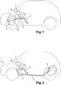
- the master cylinder 2 On conventional vehicles with a powertrain located at the front, as visible on the figure 1 , the master cylinder 2 is usually arranged at a point higher than the receiving cylinder 5, so that the bubbles coming from the receiving cylinder go up naturally in the master cylinder where they are then evacuated towards the reservoir 7 of brake fluid 6 In addition, the length of the pipes 4 is short.
- the object of the invention is in particular to provide a simple, effective and economical solution to this problem.
- the invention provides a hydraulic control device for a clutch for a motor vehicle, comprising all the features of claim 1.
- the air bubbles are trapped by the line offset devices and they are evacuated during clutch operation while progressively ascending along the line, thanks to the plurality of line offset devices, into the reservoir. brake fluid. It is thus not necessary to have expensive devices, such as a separate purge step, with in particular additional additional purge equipment, for example purge pumps, or for example additional circuits of separate outward and return lines.
- the invention also relates to a motor vehicle, comprising a clutch actuated by a hydraulic control device of the aforementioned type.
- front In the context of the present application, the terms “front”, “rear”, “left”, “right” are understood to refer to a usual reference for vehicles automobiles comprising a first longitudinal axis X, horizontal and oriented from rear to front, a transverse axis Y and a vertical axis Z directed from bottom to top.
- the X, Y axes define a horizontal plane.
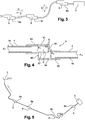
- the figure 2 shows a motor vehicle comprising an engine located in the rear part of the vehicle, connected to a gearbox via a clutch (not shown).
- the clutch is actuated by a hydraulic control device 1 comprising at the front a master cylinder 2 controlled by a clutch pedal 3 and connected by a line 4 to a receiving cylinder 5 for actuating the clutch located at the rear of the vehicle.
- the master cylinder 2 is supplied by a reservoir 7, located above the master cylinder 2 and containing brake fluid 6 at atmospheric pressure.
- the thrust force transmitted to the diaphragm causes the engine to be decoupled from the gearbox: this is the clutch release operation.
- the driver wishes to engage again, that is to say coupling the engine to the gearbox, he releases the clutch pedal 3, the restoring force then exerted by the diaphragm on the receiving cylinder 5 tending to push the hydraulic fluid towards the master cylinder 2, the two cylinders 2, 5 thus returning to their original position, that is to say their rest position.
- the clutch in this case is a normally closed clutch, which means that in the absence of action on the clutch pedal 3, the engine 1 is coupled to the gearbox.
- air bubbles manage to enter the hydraulic circuit, in particular at the level of the receiving cylinder 5, which for vehicles with an engine located at the rear, is located at the rear of the vehicle.
- the offset devices are all identical.
- a unitary example of an offset device 8 according to the invention is shown in figure 4 .
- the offset device 8 is in the form of a module which is placed on the hydraulic line 4, this module comprises a first and a second tubular portion of the same diameter, successive, offset and communicating.
- One of the tubular portions constitutes the upstream portion 81, the other the downstream portion 82 of the pipe passing through the offset device.
- Each tubular portion has a radius R1 and R2, as well as a separate central axis of revolution A1, A2 and in the same direction.
- the distance K between the two axes is less than or equal to the sum S of the radii R1 and R2 of the upstream and downstream tubular portions.
- the two pipes are offset while having their tubular casings partially superimposed.
- This partial superposition of the tubular casings is characteristic of the offset device and makes it possible to distinguish the offset device 8 from a simple bent shape of the hydraulic pipe.
- the partial superposition of the two upstream and downstream tubular portions constitutes the offset module.
- the upstream and downstream pipes may have the same radius R.
- a recess 87 has been made in the two envelopes of the two tubular portions upstream 81 and downstream 82.
- This recess 87 is made in the lower part of the casing 83 of the upstream pipe 81 and in the upper part of the casing 84 of the downstream pipe 82.
- This recess 87 is the location of the offset of the pipe, the place where the two pipes overlap, and through which the hydraulic fluid circulates 6.
- This recess 87 is at least equal to, or substantially wider than the sum S of the radii R1 and R2 of the upstream tubular portions and downstream to facilitate the movement of hydraulic fluid inside the offset module.
- the displacement of the fluid inside the offset device has a component oriented along the offset, namely perpendicular to the longitudinal direction of the pipe, due to the shape of the pipe offset.
- the lines run from front to rear and have mainly a component along the horizontal plane.
- the offset is essentially carried out perpendicular to the pipe, along the height z.
- the upstream tubular portion 81 ends in a transverse surface 85 bordering the recess 87 on the downstream side.
- the downstream tubular portion 82 begins with a transverse surface 86 to the pipe bordering the recess 87 on the upstream side.
- the transverse surface 85 of the upstream pipe 81 makes it possible to trap the air bubbles 9 of the fluid.
- the air bubbles 9 pile up near this surface. Lighter, the air bubbles 9 rise naturally, in the direction of the pipe offset and in the direction of the height, that is to say upwards, above the recess 87, in the zone offset, namely in the part of the upstream pipe above the downstream pipe.
- the air bubbles are then housed at the top of the upstream pipe.
- the bubbles are trapped by the transverse stop surface 85 of the portion of the upstream pipe 81 and remain on the upstream side of the recess. They can no longer move in the direction of the receiving cylinder because they are held by the transverse stop surface 85 of the upstream pipe. They are also maintained in the upstream pipe because it is higher than the downstream pipe, due to the offset in height, which creates a threshold effect.
- the fluid 6 moves inside the pipe 4 when the pedal is pressed in direction D, the hydraulic fluid 6 moves from the pedal 3 to the receiver 5 and the air bubbles present in the circuit are trapped by the transverse surface 85 of the upstream pipe, and do not move more in the direction of the receiver 5.
- the air bubbles follow the movement of the fluid in the direction E and are sent in the upstream direction, they do not have to cross a threshold in height and move over a distance equivalent to the volume of liquid displaced, they cross the distances separating several offset modules 8 and are gradually trapped by a new offset device. They thus progressively wind up the entire hydraulic line thanks to the play of supports on the clutch pedal, with a step on the offset devices present on the course.
- the pipe offset device 8 is connected upstream with the pipe portion 4a coming from the pedal and the master cylinder and downstream with the pipe portion 4b coming from the clutch receiver.
- upstream it should be understood that the portion of pipe coming from the pedal and the master cylinder is higher than the portion of pipe coming from the clutch receiver.
- the connection between the offset device and the hydraulic pipe portion coming from the pedal is made by inserting the pipe inside the upstream portion of the pipe of the offset module, it is the same for the connection between the portion of hydraulic line coming from the receiving cylinder and the downstream portion of the line of the offset device.
- the hydraulic line comprises at least two successive offset modules 8a, 8b in the same longitudinal plane of the vehicle, this relates in particular to the offset devices located in the flat area under the body. A slight slope is then provided between the devices, the device located near the pedal is located higher than the device located near the clutch receiver.
- the pipe portion connecting two successive offset modules 8a, 8b, 8c, 8d includes a volume of hydraulic fluid 6 between 70 and 90% of the volume of hydraulic fluid 6 displaced when the pedal is pressed 3. Such a volume allows the air bubbles to rise at least a portion separating two modules at the 'occasion of a press / release on the pedal.
- the length of the pipe portion between two successive offset modules 8a, 8b, 8c, 8d is substantially between 400mm and 600mm.
- the invention thus provides a hydraulic control device for a clutch allowing the evacuation of air bubbles during its operation, in a simple and effective manner. This guarantees that the air bubbles present in the connecting pipe, whatever their position, are brought upstream of the pipe. hydraulic, up to the tank where these are then evacuated thanks to the successive clutch / disengage actions.
Landscapes
- Engineering & Computer Science (AREA)
- Mechanical Engineering (AREA)
- General Engineering & Computer Science (AREA)
- Chemical & Material Sciences (AREA)
- Combustion & Propulsion (AREA)
- Transportation (AREA)
- Physics & Mathematics (AREA)
- Fluid Mechanics (AREA)
- Hydraulic Clutches, Magnetic Clutches, Fluid Clutches, And Fluid Joints (AREA)
Claims (9)
- Vorrichtung zur hydraulischen Steuerung einer Kupplung für ein Kraftfahrzeug (1), die einen durch ein Kupplungspedal (3) gesteuerten Geberzylinder (2), Versorgungseinrichtungen zur Versorgung des Geberzylinders (2) mit Hydraulikfluid (6) und einen Nehmerzylinder zur Betätigung der Kupplung (5) beinhaltet, wobei der Geberzylinder (2) mit dem Betätigungsnehmerzylinder (5) mittels einer Hydraulikleitung (4) verbunden ist, wobei der Kupplungsbetätigungsnehmer (5) geeignet ist, im hinteren Teil des Fahrzeugs angeordnet zu werden, und das Pedal (3) und der Geberzylinder (2) geeignet sind, im vorderen Teil des Fahrzeugs angeordnet zu werden, dadurch gekennzeichnet, dass die Hydraulikleitung (4), die geeignet ist, den hinteren mit dem vorderen Teil des Fahrzeugs zu verbinden, eine Mehrzahl (8a, 8b, 8c, 8d) von Leitungsachsversatzvorrichtungen (8) entlang ihres Verlaufs beinhaltet, wobei jede der Leitungsachsversatzvorrichtungen (8) dazu bestimmt ist, die in der Hydraulikleitung vorhandenen Luftblasen zu fangen, wobei jede Achsversatzvorrichtung (8) aus einem stromaufwärtigen rohrförmigen Abschnitt (81) und aus einem darauf folgenden und kommunizierenden stromabwärtigen rohrförmigen Abschnitt (82) besteht, wobei jeder rohrförmige Abschnitt einen Radius (R1, R2) und eine Mittelachse (A1, A2) aufweist, die verschieden und gleich gerichtet sind, wobei der Abstand (K) zwischen den beiden Mittelachsen der rohrförmigen Abschnitte kleiner als die Summe (S) der Radien (R1, R2) der stromaufwärtigen (81) und stromabwärtigen (82) rohrförmigen Abschnitte ist, so dass die Mäntel (83, 84) der rohrförmigen Abschnitte einen Überlappungsbereich aufweisen, und die Mehrzahl von Leitungsachsversatzvorrichtungen (8a, 8b, 8c, 8d) dazu bestimmt ist, das Wiederaufsteigen der Luftblasen bis zur Versorgungseinrichtung (7) zur Versorgung des Geberzylinders (2) mit Hydraulikfluid (6) zu begünstigen.
- Vorrichtung zur hydraulischen Steuerung einer Kupplung für ein Kraftfahrzeug (1) nach dem vorhergehenden Anspruch, dadurch gekennzeichnet, dass die beiden rohrförmigen Abschnitte (81, 82) der Achsversatzvorrichtung mittels eines gemeinsamen Raums (87) kommunizieren, der im unteren Teil des Mantels (83) des stromaufwärtigen rohrförmigen Abschnitts (81) und im oberen Teil des Mantels (84) des stromabwärtigen rohrförmigen Abschnitts (82) ausgeführt ist, durch den hindurch das Hydraulikfluid (6) fließt.
- Vorrichtung zur hydraulischen Steuerung einer Kupplung für ein Kraftfahrzeug (1) nach dem vorhergehenden Anspruch, dadurch gekennzeichnet, dass der Raum (87) eine Breite aufweist, die größer oder gleich der Summe (S) der Radien (R1, R2) der stromaufwärtigen (81) und stromabwärtigen (82) rohrförmigen Abschnitte ist.
- Vorrichtung zur hydraulischen Steuerung einer Kupplung für ein Kraftfahrzeug (1) nach einem der vorhergehenden Ansprüche, dadurch gekennzeichnet, dass die Hydraulikleitung (4) mindestens zwei aufeinander folgende Achsversatzvorrichtungen (8a, 8b) in derselben Längsebene des Fahrzeugs beinhaltet, wobei die in der Nähe des Pedals gelegene Achsversatzvorrichtung weiter oben als die in der Nähe des Nehmerzylinders gelegene Vorrichtung angeordnet ist.
- Vorrichtung zur hydraulischen Steuerung einer Kupplung für ein Kraftfahrzeug (1) nach einem der vorhergehenden Ansprüche, die mindestens drei aufeinander folgende Achsversatzvorrichtungen (8a, 8b, 8c, 8d) umfasst.
- Vorrichtung zur hydraulischen Steuerung einer Kupplung für ein Kraftfahrzeug (1) nach einem der vorhergehenden Ansprüche, die mindestens vier aufeinander folgende Achsversatzvorrichtungen (8a, 8b, 8c, 8d) umfasst.
- Vorrichtung zur hydraulischen Steuerung einer Kupplung für ein Kraftfahrzeug (1) nach einem der vorhergehenden Ansprüche, dadurch gekennzeichnet, dass der zwei aufeinander folgende Achsversatzvorrichtungen (8a, 8b, 8c, 8d) verbindende Leitungsabschnitt ein Hydraulikfluidvolumen (6) umfasst, das zwischen 70 und 90 % des beim Treten des Pedals (3) verdrängten Hydraulikvolumens (6) beträgt.
- Vorrichtung zur hydraulischen Steuerung einer Kupplung für ein Kraftfahrzeug (1) nach einem der vorhergehenden Ansprüche, dadurch gekennzeichnet, dass sie eine Leitungsabschnittslänge zwischen zwei aufeinander folgenden Achsversatzmodulen zwischen 400 mm und 600 mm umfasst.
- Kraftfahrzeug mit einer Vorrichtung zur hydraulischen Steuerung einer Kupplung (1) nach einem der vorhergehenden Ansprüche.
Applications Claiming Priority (2)
| Application Number | Priority Date | Filing Date | Title |
|---|---|---|---|
| FR1360056A FR3011897B1 (fr) | 2013-10-16 | 2013-10-16 | Dispositif de commande hydraulique d'un embrayage et vehicule associe |
| PCT/FR2014/052487 WO2015055913A1 (fr) | 2013-10-16 | 2014-10-01 | Dispositif de commande hydraulique d'un embrayage et véhicule associé |
Publications (2)
| Publication Number | Publication Date |
|---|---|
| EP3057820A1 EP3057820A1 (de) | 2016-08-24 |
| EP3057820B1 true EP3057820B1 (de) | 2020-04-29 |
Family
ID=49759351
Family Applications (1)
| Application Number | Title | Priority Date | Filing Date |
|---|---|---|---|
| EP14793233.9A Active EP3057820B1 (de) | 2013-10-16 | 2014-10-01 | Vorrichtung zur hydraulischen steuerung einer kupplung und fahrzeug damit |
Country Status (5)
| Country | Link |
|---|---|
| US (1) | US10094434B2 (de) |
| EP (1) | EP3057820B1 (de) |
| CN (1) | CN105636818A (de) |
| FR (1) | FR3011897B1 (de) |
| WO (1) | WO2015055913A1 (de) |
Family Cites Families (8)
| Publication number | Priority date | Publication date | Assignee | Title |
|---|---|---|---|---|
| JPS5572421A (en) * | 1978-11-22 | 1980-05-31 | Nissan Motor Co Ltd | Vibration preventive device of clutch pedal |
| DE3445743A1 (de) * | 1984-12-14 | 1986-06-19 | Knorr-Bremse AG, 8000 München | Vorrichtung zum ausruecken einer einen motorischen antrieb mit einem kompressor verbindenden kupplung |
| US5070983A (en) * | 1990-10-29 | 1991-12-10 | Automotive Products Plc | Damper for hydraulic clutch actuator |
| DE19622572B4 (de) * | 1995-06-14 | 2007-11-08 | Luk Gs Verwaltungs Kg | Hydrauliksystem und Verfahren zum Entlüften des Hydrauliksystems sowie röhrenförmiges Bauteil hierfür |
| CN101709732B (zh) * | 2009-11-24 | 2013-08-21 | 中冶建工集团有限公司 | 离合器助力器液压管路逆向加注排气法 |
| EP2705268B1 (de) * | 2011-05-06 | 2015-09-23 | Schaeffler Technologies AG & Co. KG | Hydraulische strecke mit einer entlüftungseinrichtung |
| FR2975152B1 (fr) * | 2011-05-12 | 2013-11-22 | Valeo Embrayages | Dispositif de commande hydraulique d'un embrayage. |
| CN202125487U (zh) * | 2011-07-04 | 2012-01-25 | 梁明亮 | 汽车离合器液压系统排气装置 |
-
2013
- 2013-10-16 FR FR1360056A patent/FR3011897B1/fr not_active Expired - Fee Related
-
2014
- 2014-10-01 WO PCT/FR2014/052487 patent/WO2015055913A1/fr not_active Ceased
- 2014-10-01 US US15/029,539 patent/US10094434B2/en active Active
- 2014-10-01 EP EP14793233.9A patent/EP3057820B1/de active Active
- 2014-10-01 CN CN201480056297.1A patent/CN105636818A/zh active Pending
Non-Patent Citations (1)
| Title |
|---|
| None * |
Also Published As
| Publication number | Publication date |
|---|---|
| EP3057820A1 (de) | 2016-08-24 |
| FR3011897A1 (fr) | 2015-04-17 |
| CN105636818A (zh) | 2016-06-01 |
| WO2015055913A1 (fr) | 2015-04-23 |
| FR3011897B1 (fr) | 2015-10-23 |
| US20160252145A1 (en) | 2016-09-01 |
| US10094434B2 (en) | 2018-10-09 |
Similar Documents
| Publication | Publication Date | Title |
|---|---|---|
| EP3245110B1 (de) | Bremssystem für schienenfahrzeuge und bremsverfahren für ein schienenfahrzeug mit einem solchen system | |
| FR2557527A1 (fr) | Servofrein | |
| FR2545055A1 (fr) | Amplificateur de force hydraulique, notamment pour systeme de freinage de vehicule automobile | |
| EP3057820B1 (de) | Vorrichtung zur hydraulischen steuerung einer kupplung und fahrzeug damit | |
| EP2058191A1 (de) | Hauptbremszylinder eines Fahrzeugs, der mit einer Bremsvorrichtung verbunden ist | |
| FR2482916A1 (fr) | Dispositif de fourniture de pression a une installation de regulation du glissement de freinage pour vehicule automobile | |
| FR2550149A1 (fr) | Generateur de pression de freinage pour systeme de freinage de vehicule | |
| FR2880854A1 (fr) | Dispositif de soupape de frein | |
| EP4090871B1 (de) | Verbindungsvorrichtung mit beweglicher buchse | |
| EP2522873B1 (de) | Hydraulische Kupplungssteuerung | |
| EP2208650B1 (de) | Simulator mit Spielnachstellung für Bremskraftverstärker eines Fahrzeugs | |
| FR2460241A1 (fr) | Soupape regulatrice pour installations de freinage de vehicules automobiles a deux circuits de frein | |
| EP2208652A1 (de) | Simulator eines Bremskraftverstärkers eines Fahrzeugs mit einem Dreiwegeventil | |
| EP0360697B1 (de) | Pumpenanlage, insbesondere für Bewässerung | |
| EP0642433B1 (de) | Bremsvorrichtung mit einem einzigen steuerventil für blokierschutz-und antriebsschlupfregelung | |
| FR2963302A1 (fr) | Systeme de liaison transversale pour une commande de freinage d'un vehicule automobile | |
| EP3366512B1 (de) | Ring zur aufrechterhaltung einer versenkbaren kopfstütze, einen solchen ring umfassende kopfstütze, eine solche kopfstütze umfassender fahrzeugsitz und fahrzeug, das einen solchen sitz umfasst | |
| FR2761943A1 (fr) | Dispositif de reglage de pression de fluide de freinage | |
| EP2213537A1 (de) | Behälter für einen hydraulischen Kreis, insbesondere für ein Kraftfahrzeug | |
| EP1995449A2 (de) | Verfahren zur Steuerung des Ausschaltens und automatischen Neustarts eines Fahrzeugmotors in Abhängigkeit vom Gefälle | |
| WO2002046012A1 (fr) | Servomoteur d'assistance au freinage pour vehicule automobile | |
| FR2762569A1 (fr) | Systeme de freinage hydraulique a deux circuits et deux servofreins a depression pour un vehicule automobile, ainsi que soupape d'arret pour un tel systeme | |
| FR3054187A1 (fr) | Pedale de frein articulee pour un vehicule comportant un freinage automatique | |
| EP1410941B1 (de) | Hydraulikkreis zur Betätigung eines automatisierten Fahrzeuggetriebes | |
| FR2945264A1 (fr) | Systeme de freinage notamment pour vehicule automobile, comportant un amplificateur de freinage |
Legal Events
| Date | Code | Title | Description |
|---|---|---|---|
| PUAI | Public reference made under article 153(3) epc to a published international application that has entered the european phase |
Free format text: ORIGINAL CODE: 0009012 |
|
| 17P | Request for examination filed |
Effective date: 20160325 |
|
| AK | Designated contracting states |
Kind code of ref document: A1 Designated state(s): AL AT BE BG CH CY CZ DE DK EE ES FI FR GB GR HR HU IE IS IT LI LT LU LV MC MK MT NL NO PL PT RO RS SE SI SK SM TR |
|
| AX | Request for extension of the european patent |
Extension state: BA ME |
|
| DAX | Request for extension of the european patent (deleted) | ||
| STAA | Information on the status of an ep patent application or granted ep patent |
Free format text: STATUS: EXAMINATION IS IN PROGRESS |
|
| 17Q | First examination report despatched |
Effective date: 20190418 |
|
| GRAP | Despatch of communication of intention to grant a patent |
Free format text: ORIGINAL CODE: EPIDOSNIGR1 |
|
| STAA | Information on the status of an ep patent application or granted ep patent |
Free format text: STATUS: GRANT OF PATENT IS INTENDED |
|
| INTG | Intention to grant announced |
Effective date: 20191125 |
|
| GRAS | Grant fee paid |
Free format text: ORIGINAL CODE: EPIDOSNIGR3 |
|
| GRAA | (expected) grant |
Free format text: ORIGINAL CODE: 0009210 |
|
| STAA | Information on the status of an ep patent application or granted ep patent |
Free format text: STATUS: THE PATENT HAS BEEN GRANTED |
|
| AK | Designated contracting states |
Kind code of ref document: B1 Designated state(s): AL AT BE BG CH CY CZ DE DK EE ES FI FR GB GR HR HU IE IS IT LI LT LU LV MC MK MT NL NO PL PT RO RS SE SI SK SM TR |
|
| REG | Reference to a national code |
Ref country code: GB Ref legal event code: FG4D Free format text: NOT ENGLISH |
|
| REG | Reference to a national code |
Ref country code: CH Ref legal event code: EP |
|
| REG | Reference to a national code |
Ref country code: DE Ref legal event code: R096 Ref document number: 602014064597 Country of ref document: DE |
|
| REG | Reference to a national code |
Ref country code: AT Ref legal event code: REF Ref document number: 1262795 Country of ref document: AT Kind code of ref document: T Effective date: 20200515 |
|
| REG | Reference to a national code |
Ref country code: IE Ref legal event code: FG4D Free format text: LANGUAGE OF EP DOCUMENT: FRENCH |
|
| REG | Reference to a national code |
Ref country code: NL Ref legal event code: MP Effective date: 20200429 |
|
| REG | Reference to a national code |
Ref country code: LT Ref legal event code: MG4D |
|
| PG25 | Lapsed in a contracting state [announced via postgrant information from national office to epo] |
Ref country code: LT Free format text: LAPSE BECAUSE OF FAILURE TO SUBMIT A TRANSLATION OF THE DESCRIPTION OR TO PAY THE FEE WITHIN THE PRESCRIBED TIME-LIMIT Effective date: 20200429 Ref country code: SE Free format text: LAPSE BECAUSE OF FAILURE TO SUBMIT A TRANSLATION OF THE DESCRIPTION OR TO PAY THE FEE WITHIN THE PRESCRIBED TIME-LIMIT Effective date: 20200429 Ref country code: NO Free format text: LAPSE BECAUSE OF FAILURE TO SUBMIT A TRANSLATION OF THE DESCRIPTION OR TO PAY THE FEE WITHIN THE PRESCRIBED TIME-LIMIT Effective date: 20200729 Ref country code: GR Free format text: LAPSE BECAUSE OF FAILURE TO SUBMIT A TRANSLATION OF THE DESCRIPTION OR TO PAY THE FEE WITHIN THE PRESCRIBED TIME-LIMIT Effective date: 20200730 Ref country code: IS Free format text: LAPSE BECAUSE OF FAILURE TO SUBMIT A TRANSLATION OF THE DESCRIPTION OR TO PAY THE FEE WITHIN THE PRESCRIBED TIME-LIMIT Effective date: 20200829 Ref country code: PT Free format text: LAPSE BECAUSE OF FAILURE TO SUBMIT A TRANSLATION OF THE DESCRIPTION OR TO PAY THE FEE WITHIN THE PRESCRIBED TIME-LIMIT Effective date: 20200831 Ref country code: FI Free format text: LAPSE BECAUSE OF FAILURE TO SUBMIT A TRANSLATION OF THE DESCRIPTION OR TO PAY THE FEE WITHIN THE PRESCRIBED TIME-LIMIT Effective date: 20200429 |
|
| REG | Reference to a national code |
Ref country code: AT Ref legal event code: MK05 Ref document number: 1262795 Country of ref document: AT Kind code of ref document: T Effective date: 20200429 |
|
| PG25 | Lapsed in a contracting state [announced via postgrant information from national office to epo] |
Ref country code: HR Free format text: LAPSE BECAUSE OF FAILURE TO SUBMIT A TRANSLATION OF THE DESCRIPTION OR TO PAY THE FEE WITHIN THE PRESCRIBED TIME-LIMIT Effective date: 20200429 Ref country code: LV Free format text: LAPSE BECAUSE OF FAILURE TO SUBMIT A TRANSLATION OF THE DESCRIPTION OR TO PAY THE FEE WITHIN THE PRESCRIBED TIME-LIMIT Effective date: 20200429 Ref country code: RS Free format text: LAPSE BECAUSE OF FAILURE TO SUBMIT A TRANSLATION OF THE DESCRIPTION OR TO PAY THE FEE WITHIN THE PRESCRIBED TIME-LIMIT Effective date: 20200429 Ref country code: BG Free format text: LAPSE BECAUSE OF FAILURE TO SUBMIT A TRANSLATION OF THE DESCRIPTION OR TO PAY THE FEE WITHIN THE PRESCRIBED TIME-LIMIT Effective date: 20200729 |
|
| PG25 | Lapsed in a contracting state [announced via postgrant information from national office to epo] |
Ref country code: AL Free format text: LAPSE BECAUSE OF FAILURE TO SUBMIT A TRANSLATION OF THE DESCRIPTION OR TO PAY THE FEE WITHIN THE PRESCRIBED TIME-LIMIT Effective date: 20200429 Ref country code: NL Free format text: LAPSE BECAUSE OF FAILURE TO SUBMIT A TRANSLATION OF THE DESCRIPTION OR TO PAY THE FEE WITHIN THE PRESCRIBED TIME-LIMIT Effective date: 20200429 |
|
| PG25 | Lapsed in a contracting state [announced via postgrant information from national office to epo] |
Ref country code: CZ Free format text: LAPSE BECAUSE OF FAILURE TO SUBMIT A TRANSLATION OF THE DESCRIPTION OR TO PAY THE FEE WITHIN THE PRESCRIBED TIME-LIMIT Effective date: 20200429 Ref country code: RO Free format text: LAPSE BECAUSE OF FAILURE TO SUBMIT A TRANSLATION OF THE DESCRIPTION OR TO PAY THE FEE WITHIN THE PRESCRIBED TIME-LIMIT Effective date: 20200429 Ref country code: ES Free format text: LAPSE BECAUSE OF FAILURE TO SUBMIT A TRANSLATION OF THE DESCRIPTION OR TO PAY THE FEE WITHIN THE PRESCRIBED TIME-LIMIT Effective date: 20200429 Ref country code: EE Free format text: LAPSE BECAUSE OF FAILURE TO SUBMIT A TRANSLATION OF THE DESCRIPTION OR TO PAY THE FEE WITHIN THE PRESCRIBED TIME-LIMIT Effective date: 20200429 Ref country code: SM Free format text: LAPSE BECAUSE OF FAILURE TO SUBMIT A TRANSLATION OF THE DESCRIPTION OR TO PAY THE FEE WITHIN THE PRESCRIBED TIME-LIMIT Effective date: 20200429 Ref country code: AT Free format text: LAPSE BECAUSE OF FAILURE TO SUBMIT A TRANSLATION OF THE DESCRIPTION OR TO PAY THE FEE WITHIN THE PRESCRIBED TIME-LIMIT Effective date: 20200429 Ref country code: DK Free format text: LAPSE BECAUSE OF FAILURE TO SUBMIT A TRANSLATION OF THE DESCRIPTION OR TO PAY THE FEE WITHIN THE PRESCRIBED TIME-LIMIT Effective date: 20200429 Ref country code: IT Free format text: LAPSE BECAUSE OF FAILURE TO SUBMIT A TRANSLATION OF THE DESCRIPTION OR TO PAY THE FEE WITHIN THE PRESCRIBED TIME-LIMIT Effective date: 20200429 |
|
| REG | Reference to a national code |
Ref country code: DE Ref legal event code: R097 Ref document number: 602014064597 Country of ref document: DE |
|
| PG25 | Lapsed in a contracting state [announced via postgrant information from national office to epo] |
Ref country code: SK Free format text: LAPSE BECAUSE OF FAILURE TO SUBMIT A TRANSLATION OF THE DESCRIPTION OR TO PAY THE FEE WITHIN THE PRESCRIBED TIME-LIMIT Effective date: 20200429 Ref country code: PL Free format text: LAPSE BECAUSE OF FAILURE TO SUBMIT A TRANSLATION OF THE DESCRIPTION OR TO PAY THE FEE WITHIN THE PRESCRIBED TIME-LIMIT Effective date: 20200429 |
|
| PLBE | No opposition filed within time limit |
Free format text: ORIGINAL CODE: 0009261 |
|
| STAA | Information on the status of an ep patent application or granted ep patent |
Free format text: STATUS: NO OPPOSITION FILED WITHIN TIME LIMIT |
|
| 26N | No opposition filed |
Effective date: 20210201 |
|
| PG25 | Lapsed in a contracting state [announced via postgrant information from national office to epo] |
Ref country code: SI Free format text: LAPSE BECAUSE OF FAILURE TO SUBMIT A TRANSLATION OF THE DESCRIPTION OR TO PAY THE FEE WITHIN THE PRESCRIBED TIME-LIMIT Effective date: 20200429 |
|
| REG | Reference to a national code |
Ref country code: CH Ref legal event code: PL |
|
| PG25 | Lapsed in a contracting state [announced via postgrant information from national office to epo] |
Ref country code: LU Free format text: LAPSE BECAUSE OF NON-PAYMENT OF DUE FEES Effective date: 20201001 Ref country code: MC Free format text: LAPSE BECAUSE OF FAILURE TO SUBMIT A TRANSLATION OF THE DESCRIPTION OR TO PAY THE FEE WITHIN THE PRESCRIBED TIME-LIMIT Effective date: 20200429 |
|
| REG | Reference to a national code |
Ref country code: BE Ref legal event code: MM Effective date: 20201031 |
|
| PG25 | Lapsed in a contracting state [announced via postgrant information from national office to epo] |
Ref country code: LI Free format text: LAPSE BECAUSE OF NON-PAYMENT OF DUE FEES Effective date: 20201031 Ref country code: CH Free format text: LAPSE BECAUSE OF NON-PAYMENT OF DUE FEES Effective date: 20201031 Ref country code: BE Free format text: LAPSE BECAUSE OF NON-PAYMENT OF DUE FEES Effective date: 20201031 |
|
| PG25 | Lapsed in a contracting state [announced via postgrant information from national office to epo] |
Ref country code: IE Free format text: LAPSE BECAUSE OF NON-PAYMENT OF DUE FEES Effective date: 20201001 |
|
| PG25 | Lapsed in a contracting state [announced via postgrant information from national office to epo] |
Ref country code: TR Free format text: LAPSE BECAUSE OF FAILURE TO SUBMIT A TRANSLATION OF THE DESCRIPTION OR TO PAY THE FEE WITHIN THE PRESCRIBED TIME-LIMIT Effective date: 20200429 Ref country code: MT Free format text: LAPSE BECAUSE OF FAILURE TO SUBMIT A TRANSLATION OF THE DESCRIPTION OR TO PAY THE FEE WITHIN THE PRESCRIBED TIME-LIMIT Effective date: 20200429 Ref country code: CY Free format text: LAPSE BECAUSE OF FAILURE TO SUBMIT A TRANSLATION OF THE DESCRIPTION OR TO PAY THE FEE WITHIN THE PRESCRIBED TIME-LIMIT Effective date: 20200429 |
|
| PG25 | Lapsed in a contracting state [announced via postgrant information from national office to epo] |
Ref country code: MK Free format text: LAPSE BECAUSE OF FAILURE TO SUBMIT A TRANSLATION OF THE DESCRIPTION OR TO PAY THE FEE WITHIN THE PRESCRIBED TIME-LIMIT Effective date: 20200429 |
|
| P01 | Opt-out of the competence of the unified patent court (upc) registered |
Effective date: 20230608 |
|
| PGFP | Annual fee paid to national office [announced via postgrant information from national office to epo] |
Ref country code: GB Payment date: 20231020 Year of fee payment: 10 |
|
| PGFP | Annual fee paid to national office [announced via postgrant information from national office to epo] |
Ref country code: FR Payment date: 20231026 Year of fee payment: 10 Ref country code: DE Payment date: 20231020 Year of fee payment: 10 |
|
| REG | Reference to a national code |
Ref country code: DE Ref legal event code: R119 Ref document number: 602014064597 Country of ref document: DE |
|
| GBPC | Gb: european patent ceased through non-payment of renewal fee |
Effective date: 20241001 |
|
| PG25 | Lapsed in a contracting state [announced via postgrant information from national office to epo] |
Ref country code: DE Free format text: LAPSE BECAUSE OF NON-PAYMENT OF DUE FEES Effective date: 20250501 |
|
| PG25 | Lapsed in a contracting state [announced via postgrant information from national office to epo] |
Ref country code: GB Free format text: LAPSE BECAUSE OF NON-PAYMENT OF DUE FEES Effective date: 20241001 |
|
| PG25 | Lapsed in a contracting state [announced via postgrant information from national office to epo] |
Ref country code: FR Free format text: LAPSE BECAUSE OF NON-PAYMENT OF DUE FEES Effective date: 20241031 |