EP3058431B1 - Verfahren und vorrichtung zur geländeidentifikation während des fluges einer mikrodrohne - Google Patents
Verfahren und vorrichtung zur geländeidentifikation während des fluges einer mikrodrohne Download PDFInfo
- Publication number
- EP3058431B1 EP3058431B1 EP14789213.7A EP14789213A EP3058431B1 EP 3058431 B1 EP3058431 B1 EP 3058431B1 EP 14789213 A EP14789213 A EP 14789213A EP 3058431 B1 EP3058431 B1 EP 3058431B1
- Authority
- EP
- European Patent Office
- Prior art keywords
- sensor
- optical flow
- microdrone
- detection
- detection zone
- Prior art date
- Legal status (The legal status is an assumption and is not a legal conclusion. Google has not performed a legal analysis and makes no representation as to the accuracy of the status listed.)
- Active
Links
Images




Classifications
-
- G—PHYSICS
- G05—CONTROLLING; REGULATING
- G05D—SYSTEMS FOR CONTROLLING OR REGULATING NON-ELECTRIC VARIABLES
- G05D1/00—Control of position, course, altitude or attitude of land, water, air or space vehicles, e.g. using automatic pilots
- G05D1/04—Control of altitude or depth
- G05D1/06—Rate of change of altitude or depth
- G05D1/0607—Rate of change of altitude or depth specially adapted for aircraft
-
- B—PERFORMING OPERATIONS; TRANSPORTING
- B64—AIRCRAFT; AVIATION; COSMONAUTICS
- B64U—UNMANNED AERIAL VEHICLES [UAV]; EQUIPMENT THEREFOR
- B64U10/00—Type of UAV
- B64U10/80—UAVs characterised by their small size, e.g. micro air vehicles [MAV]
-
- B—PERFORMING OPERATIONS; TRANSPORTING
- B64—AIRCRAFT; AVIATION; COSMONAUTICS
- B64U—UNMANNED AERIAL VEHICLES [UAV]; EQUIPMENT THEREFOR
- B64U50/00—Propulsion; Power supply
- B64U50/10—Propulsion
- B64U50/19—Propulsion using electrically powered motors
-
- G—PHYSICS
- G01—MEASURING; TESTING
- G01C—MEASURING DISTANCES, LEVELS OR BEARINGS; SURVEYING; NAVIGATION; GYROSCOPIC INSTRUMENTS; PHOTOGRAMMETRY OR VIDEOGRAMMETRY
- G01C21/00—Navigation; Navigational instruments not provided for in groups G01C1/00 - G01C19/00
- G01C21/20—Instruments for performing navigational calculations
-
- G—PHYSICS
- G01—MEASURING; TESTING
- G01C—MEASURING DISTANCES, LEVELS OR BEARINGS; SURVEYING; NAVIGATION; GYROSCOPIC INSTRUMENTS; PHOTOGRAMMETRY OR VIDEOGRAMMETRY
- G01C23/00—Combined instruments indicating more than one navigational value, e.g. for aircraft; Combined measuring devices for measuring two or more variables of movement, e.g. distance, speed or acceleration
-
- G—PHYSICS
- G01—MEASURING; TESTING
- G01F—MEASURING VOLUME, VOLUME FLOW, MASS FLOW OR LIQUID LEVEL; METERING BY VOLUME
- G01F1/00—Measuring the volume flow or mass flow of fluid or fluent solid material wherein the fluid passes through a meter in a continuous flow
-
- G—PHYSICS
- G05—CONTROLLING; REGULATING
- G05D—SYSTEMS FOR CONTROLLING OR REGULATING NON-ELECTRIC VARIABLES
- G05D1/00—Control of position, course, altitude or attitude of land, water, air or space vehicles, e.g. using automatic pilots
- G05D1/0094—Control of position, course, altitude or attitude of land, water, air or space vehicles, e.g. using automatic pilots involving pointing a payload, e.g. camera, weapon, sensor, towards a fixed or moving target
-
- G—PHYSICS
- G05—CONTROLLING; REGULATING
- G05D—SYSTEMS FOR CONTROLLING OR REGULATING NON-ELECTRIC VARIABLES
- G05D1/00—Control of position, course, altitude or attitude of land, water, air or space vehicles, e.g. using automatic pilots
- G05D1/20—Control system inputs
- G05D1/24—Arrangements for determining position or orientation
- G05D1/243—Means capturing signals occurring naturally from the environment, e.g. ambient optical, acoustic, gravitational or magnetic signals
- G05D1/2435—Extracting 3D information
-
- G—PHYSICS
- G05—CONTROLLING; REGULATING
- G05D—SYSTEMS FOR CONTROLLING OR REGULATING NON-ELECTRIC VARIABLES
- G05D1/00—Control of position, course, altitude or attitude of land, water, air or space vehicles, e.g. using automatic pilots
- G05D1/60—Intended control result
- G05D1/617—Safety or protection, e.g. defining protection zones around obstacles or avoiding hazards
- G05D1/622—Obstacle avoidance
- G05D1/628—Obstacle avoidance following the obstacle profile, e.g. a wall or undulated terrain
-
- G—PHYSICS
- G05—CONTROLLING; REGULATING
- G05D—SYSTEMS FOR CONTROLLING OR REGULATING NON-ELECTRIC VARIABLES
- G05D1/00—Control of position, course, altitude or attitude of land, water, air or space vehicles, e.g. using automatic pilots
- G05D1/60—Intended control result
- G05D1/656—Interaction with payloads or external entities
- G05D1/689—Pointing payloads towards fixed or moving targets
-
- G—PHYSICS
- G08—SIGNALLING
- G08G—TRAFFIC CONTROL SYSTEMS
- G08G5/00—Traffic control systems for aircraft
- G08G5/70—Arrangements for monitoring traffic-related situations or conditions
- G08G5/74—Arrangements for monitoring traffic-related situations or conditions for monitoring terrain
-
- B—PERFORMING OPERATIONS; TRANSPORTING
- B64—AIRCRAFT; AVIATION; COSMONAUTICS
- B64U—UNMANNED AERIAL VEHICLES [UAV]; EQUIPMENT THEREFOR
- B64U2101/00—UAVs specially adapted for particular uses or applications
- B64U2101/55—UAVs specially adapted for particular uses or applications for life-saving or rescue operations; for medical use
-
- B—PERFORMING OPERATIONS; TRANSPORTING
- B64—AIRCRAFT; AVIATION; COSMONAUTICS
- B64U—UNMANNED AERIAL VEHICLES [UAV]; EQUIPMENT THEREFOR
- B64U2201/00—UAVs characterised by their flight controls
- B64U2201/10—UAVs characterised by their flight controls autonomous, i.e. by navigating independently from ground or air stations, e.g. by using inertial navigation systems [INS]
-
- G—PHYSICS
- G05—CONTROLLING; REGULATING
- G05D—SYSTEMS FOR CONTROLLING OR REGULATING NON-ELECTRIC VARIABLES
- G05D2105/00—Specific applications of the controlled vehicles
- G05D2105/80—Specific applications of the controlled vehicles for information gathering, e.g. for academic research
-
- G—PHYSICS
- G05—CONTROLLING; REGULATING
- G05D—SYSTEMS FOR CONTROLLING OR REGULATING NON-ELECTRIC VARIABLES
- G05D2109/00—Types of controlled vehicles
- G05D2109/20—Aircraft, e.g. drones
- G05D2109/25—Rotorcrafts
- G05D2109/254—Flying platforms, e.g. multicopters
-
- G—PHYSICS
- G05—CONTROLLING; REGULATING
- G05D—SYSTEMS FOR CONTROLLING OR REGULATING NON-ELECTRIC VARIABLES
- G05D2111/00—Details of signals used for control of position, course, altitude or attitude of land, water, air or space vehicles
- G05D2111/10—Optical signals
-
- G—PHYSICS
- G05—CONTROLLING; REGULATING
- G05D—SYSTEMS FOR CONTROLLING OR REGULATING NON-ELECTRIC VARIABLES
- G05D2111/00—Details of signals used for control of position, course, altitude or attitude of land, water, air or space vehicles
- G05D2111/60—Combination of two or more signals
- G05D2111/63—Combination of two or more signals of the same type, e.g. stereovision or optical flow
- G05D2111/65—Combination of two or more signals of the same type, e.g. stereovision or optical flow taken successively, e.g. visual odometry or optical flow
Definitions
- the IROS article presents a microdrone, namely a helicopter with two rotors, comprising a main body, to which is attached a terrain detection head provided with a "composite eye".
- the composite eye is made up of four optical flow sensors distributed over the detection head.
- the detection head is able to rotate relative to the main body thanks to a stepping motor.
- the angle of the detection head relative to the main body is controlled so that the orientation of the detection head remains the same in the terrestrial frame and compensates for the angle of the main body in the landmark.
- WO 2004/027434 A1 present in his figure 1 a helicopter stabilization system 1 comprising a nacelle 5 with optical sensor 3 and rotation sensors 9 and 10.
- the nacelle 5 is fixed relative to the helicopter 1.
- This known system is complex and very sensitive to vibrations.
- OCTAVE a bioinspired visuo-motor control system for the guidance of Micro-Air-Vehicles "by Franck Ruffier et al., PROCEEDINGS OF SPIE, SPIE, US, vol. 5119, no. 1, May 19, 2003, pages 1-12 deals with a visual autopilot for small flying machines.
- An object of the present invention is to provide an improved autopilot for drone, microdrone or nanodrone in order to allow the drone, microdrone or nanodrone to better navigate in a steep and / or moving environment.
- Another object of the present invention is to provide an autopilot for microdrone or nanodrone without an inertial unit.
- an inertial unit can only be loaded onto a microdrone or nanodrone with difficulty, due to its size, its weight, and its computing power requirements.
- a device as defined above, characterized in that the controller is adapted to estimate the direction of the perpendicular to the surface in said reference frame on the basis of said signals, and to rotate, using said orientation system, the line of sight of the vision zone of each sensor in a direction separated by a determined reorientation angle from the direction of said perpendicular.
- the device for locating the surface By reorienting the line of sight of the detection zone of the sensor at a determined reorientation angle relative to the direction of the perpendicular to the surface, the device for locating the surface according to the invention makes it possible to measure a quantity as a function of the distance to surrounding objects more accurate.
- the machine can thus move without hindrance, avoiding possible obstacles which it can detect in advance, for example by orienting the line of sight towards the direction of movement in the presence of a steep obstacle.
- the invention also relates to an autonomous displacement aerial microdrone comprising a device as defined above, the controller being adapted to control the actuator so as to align the ascent axis of the detection head with the estimated direction of perpendicular to the surface and thus to maintain the axis of advance of the detection head parallel to the local slope of the surface overflown by the microdrone.
- the microdrone further comprises a gyrometer and / or an anemometer for controlling the linear speed of advance of the microdrone.
- the present invention preferably applies to large-scale drones, microdrones and flying nanodrones equipped with optical flow sensors.
- the invention is not limited to this. It can also be applied to other mobile devices at a distance from a surface, such as a fish robot, a spaceship, etc.
- distance sensors such as ultrasonic sensors, laser sensors, radar sensors, sonar sensors, etc., or sensors measuring a quantity depending on the distance such as a sensor based on the electrical direction, can also be used within the framework of the invention.
- the figure 1 shows a microdrone 2 according to the invention.
- This microdrone weighing approximately 0.08 kg is a helicopter with two rotors 4, 6 with a wingspan of approximately 0.5 m.
- Microdrone 2 is able to fly autonomously by controlling its linear advance speed and its altitude on the basis of optical flux measurements. In particular, it can follow a floor and a ceiling and land. It has the particularity of being able to navigate without measurements in the Earth's inertial reference frame.
- Microdrones or nanodrones of this type find applications in search, reconnaissance or rescue missions, especially when the terrain is steep or in the middle of buildings and / or when navigation by GPS is not possible or desirable.
- the microdrone 2 comprises, in addition to the two rotors 4, 6, two electric motors 8, 10 for driving the rotors, a main body 12, and a device for locating terrain 14.
- the main body 12 defines a longitudinal axis XX . It comprises a printed circuit 16 and a bar 18 for reinforcing the printed circuit 16, preferably made of carbon fibers.
- the reinforcing bar 18 preferably has a length of about 0.25 m.
- a gyrometer 20 measuring the pitch speed of the microdrone 2 is placed on the printed circuit 16.
- the land marking device 14 is delimited at the figure 1 by dotted lines. It includes a field detection head 22, a detection area orientation system 24 and a controller 26 controlling the microdrone 2.
- the terrain detection head 22 defines a local coordinate system L linked to the detection head, preferably orthonormal, with an origin E (cf. figure 2 ) at the center of the detection head 22, a feed axis Xe, a drift axis Ye, and an ascent axis Ze.
- the detection head 22 is provided with four optical flow sensors 28 distributed thereon.
- a rear ventral sensor 28.2 capable of measuring a rear ventral optical flow ⁇ vd
- a front dorsal sensor 28.3 capable of measuring a front dorsal optical flow ⁇ da
- a rear back sensor 28.4 able to measure a rear back optical flow ⁇ dd .
- Each optical flow sensor 28 covers a detection zone ZV centered on a line of sight ZC.
- Each optical flow sensor 28 preferably comprises a set of five local movement sensors separated by a known angle.
- the detection head 22 can also have lateral optical flow sensors.
- the detection head 22 also has an anemometer 30 measuring the speed of the air in flight.
- the detection head 22 can be equipped with gyro-stabilization sensors, such as GPS sensors or gyrometers. These sensors make it possible to take into account the frequent rocking movements of the microdrone 2 in flight and thus to improve the measurements of the optical flow sensors 28.
- the detection head 22 may have optical flow sensors with a camera with a low field of view or at very wide angle.
- Optical flow sensors can also include a combination of a camera and a mirror to create a panoramic visual field.
- the ZV detection zone orientation system 24 comprises a motor 32, preferably a stepping motor, combined with a reduction gear 34.
- the motor 32 makes it possible to rotate the detection head 22 around the drift axis Ye, and thus to modify the detection zone ZV of the optical flow sensors 28.
- the controller 26 is a microcontroller placed on the printed circuit 16.
- the figure 2 shows microdrone 2 in flight over a terrain T with local slope P and surface S.
- the term "terrain” refers to any type of relief or interface that the microdrone is led to follow in flight. It can in particular be a ground, a ceiling, the surface of a body of water, a wall, an underwater bottom, etc.
- R a terrestrial inertial frame with an origin O and three axes Xo (transverse), Yo (longitudinal) and Zo (vertical).
- ⁇ the elevation angle between the ascent axis Ze of the detection head 22 and the line of sight ZC of the detection zone ZV of an optical flow sensor 28.
- the elevation angle ⁇ is around 23 °, and the detection zone ZV covers approximately 24 ° times 12 °.
- the vector V represents the instantaneous linear speed of the microdrone 2.
- ⁇ is the angle between the vector V and the advance axis Xe of the detection head 22.
- Vx the component of the linear speed V along the feed axis Xe
- Vy the component of the linear speed V along the drift axis Ye
- Vz the component of the linear speed V along the ascent axis Ze.
- the angle ⁇ is the angle between the local slope P of the terrain T overflown by the microdrone 2 and the horizontal Xo-Yo of the terrestrial frame of reference R.
- the distance Dsurface is the distance between the surface S of the ground T and the center E of the detection head 22 according to the normal N to the slope P of the ground T.
- the angle ⁇ pitch is the angle between the longitudinal axis XX of microdrone 2 and the horizontal Xo-Yo of the terrestrial frame of reference R.
- the angle ⁇ head is the angle between the advance axis Xe of the detection head 22 and the horizontal Xo-Yo of the terrestrial reference frame R.
- the angle ⁇ EiR is the angle between the longitudinal axis XX of the microdrone 2 and the advance axis Xe of the detection head 22.
- the angle ⁇ head / slope is the angle between the advance axis Xe of the detection head 22 and the local slope P of the terrain T.
- Each control loop B1, B2, B3 is delimited by dotted lines.
- control loop B2 is identical to the corresponding control loop described in the article IROS.
- control loop reference is made to this article, the corresponding content of which is incorporated in the present description.
- control loop B1 is comparable to the corresponding control loop described in the article IROS. In particular, it also contains a feed controller 35.
- feed controller 35 for a detailed explanation of the identical elements of these two control loops, reference is made to this article, the corresponding content of which is incorporated in the present description.
- control loop B1 Compared to the control loop of the linear speed of advance known from the article IROS, the control loop B1 according to the invention also takes into account the measurements of the anemometer 30 and the measurements of the gyrometer 20 to using two additional control loops B4 and B5 nested in the control loop B1 and using respectively an air speed controller 36 and a pitch speed controller 38.
- the loops B1, B4 and B5 cooperate in the following way:
- the advance controller 35 generates an air speed setpoint as a function of the result of the comparison between the sum of the ventral and dorsal optical fluxes ⁇ vtrl + ⁇ drsl (with ⁇ vtrl proportional to ( ⁇ va + ⁇ vd ) and ⁇ drsl proportional to ( ⁇ da + ⁇ dd )) measured and a setpoint ⁇ sum setpoint FO .
- the air speed setpoint is then compared to the air speed measured by the anemometer 30. Depending on the result of this comparison, the air speed controller 36 generates a setpoint of the pitch speed of the microdrone 2.
- the pitch speed setpoint value is then compared to the pitch speed measured by the gyrometer 20. As a result of this comparison, the pitch speed controller 38 determines the thrust difference between the two rotors ⁇ rotors which is necessary to obtain the desired linear speed of advance.
- the detection head 22 of the microdrone 2 is fixed relative to the main body 12, so that the advance axis Xe of the detection head 22 is always parallel to the longitudinal axis XX of the main body 12. It can be seen that during the overflight of the slope P, the detection zones ZV of the optical flow sensors are oriented towards the rear relative to the terrain T compared to the overflight of a flat terrain. Consequently, microdrone 2 does not detect the discontinuity u until late at position Xnr.
- the Applicant has discovered that the detection of discontinuities in the ground and thus the navigation of the microdrone 2 is significantly improved by turning the detection head 22 and thus the detection zones ZV of the optical flow sensors as a function of the direction, in the reference frame.
- local L of the maximum optical flux detected by the optical flux sensors.
- the direction of maximum optical flow corresponds, in particular in the presence of the control loop B2 leading the microdrone 2 to follow the terrain T, to the direction in which the distance between the center E of the detection head 22 and the surface S of the ground T is minimal.
- the direction M of maximum optical flux coincides with the direction of the normal N to the surface S of the terrain T passing through the center E of the detection head 22. It could also be said that the direction of optical flux maximum is the direction in which one “looks” straight on the surface S of terrain T overflown.
- the direction M of maximum optical flux is subsequently identified in the local coordinate system L by the angle ⁇ ⁇ head / slope which it supports with the ascent axis Ze.
- the detection head 22 is turned using the motor 32 so that the line of sight ZC of the detection zone ZV of the front ventral sensor 28.1 is separated by a determined reorientation angle ⁇ from direction M of maximum optical flux.
- the reorientation angle ⁇ is fixed so that the front ventral sensor 28.1 "looks" sufficiently forward when the microdrone 2 follows a terrain T.
- the reorientation angle ⁇ is between 0 ° and 90 °, and, in a particularly preferred manner, the reorientation angle ⁇ is substantially equal to 23 °.
- the elevation angle ⁇ i.e. the fixed angle between the ascent axis Ze of the detection head 22 and the line of sight ZC of the detection area ZV the front ventral optical flux sensor 28.1
- the control loop B3 maintains the advance axis Xe of the detection head 22 parallel to the local slope P of a terrain T overflown by the microdrone 2.
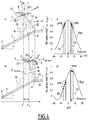
- the figure 4a shows the microdrone 2 with the servo loop B3 in action, i.e. when the detection head 22 is slaved in rotation around the axis of drift Ye so as to respect the reorientation angle ⁇ which is fixed to the value of the elevation angle ⁇ . It can be seen that the detection zone ZV of the front ventral optical flux sensor 28.1 is straightened relative to the figure 4b ). Thus, the discontinuity u is detected earlier by the microdrone 2 at the position Xr.
- the figure 4c ) shows f ( ⁇ ) for the case shown in figure 4a ), and the figure 4d ) shows f ( ⁇ ) for the case shown in figure 4b ).
- the measurement points pma of the five local motion sensors of the front ventral optical flow sensor 28.1 and the measurement points pmd of the five local motion sensors of the rear ventral optical flow sensor are indicated. 28.2.
- control loop B2 uses the optical flow measurements of the optical flow sensors 28 to maintain the ratio between the speed of advance of the microdrone 2 and the distance D surface to the surface S constant, which results in a tracking of the terrain and therefore the speed vector is aligned with the tracked surface.
- Trust ⁇ i X ′ ⁇ b - ⁇ ⁇ i my median ⁇ ⁇ i my
- a decrease in the confidence index corresponds to a higher similarity between the optical flux measurements and the approximate cosine square function.
- the angle ⁇ ⁇ head / slope is only validated if the confidence index is below a determined threshold.
- the figure 5 shows an experiment carried out with two microdrones K1 and K2.
- the microdrone K1 was equipped with the control loop B3 according to the invention constantly reorienting its detection head 22 parallel to the ground, while the detection head 22 of the microdrone K2 was fixed relative to the main body 12.
- the task of the two microdrones K1 and K2 was to navigate in a steep environment Q comprising a sharp relief H. It was found that the microdrone K2 detected the sharp relief H late and consequently crashed against it. On the other hand, thanks to the method of reorientation of the detection zones according to the invention, the microdrone K1 managed to negotiate the sharp relief H.
- the figure 5 shows the trajectories I1 (dotted lines) and I2 (solid line) of microdrones K1 and K2.
- the figure 6 shows a second embodiment of a microdrone 2 according to the invention. We are interested here only in the differences compared to the first embodiment according to the figure 1 . For the elements common to the two embodiments, reference is made to the description above.
- the detection head 22 is fixed to the main body 12 by a rod 40. No relative movement between the detection head 22 and the main body 12 is therefore possible.
- the detection head 22 is mounted on the body main 12 so that the feed axis Xe is substantially parallel to the longitudinal axis XX of the main body 12.
- the optical flow sensor 28 here consists of a matrix 42 of 84 x 15 photodetectors covering a detection field of substantially 360 ° x 60 ° around the drift axis Ye.
- a subset is chosen with four groups G1 to G4 which cover detection zones ZV similar to those of the first embodiment according to the figure 1 .
- the servo loop B3 is installed in this second microdrone so as to select in real time different subsets of photodetectors for the measurement of optical fluxes as a function of the estimated reorientation angle ⁇ .
- the figure 7 shows an example of the control loop B3 as it is implemented in microdrone 2 according to the figures 1 and 6 .
- the optical flow sensors 28 measure the optical flow ⁇ in one or two dimensions (1D or 2D) in several detection zones ZV.
- the microcontroller 26 estimates the direction of the perpendicular to the surface S overflown in the reference L of the detection head 22.
- the detection head 22 is reoriented so to align its axis of advance Xe perpendicular to the perpendicular to the surface S overflown.
- the control loop B3 resumes with the first step 101, and so on.
- the figure 8 shows a variant of the servo loop B3 using distance sensor measurements instead of optical flow sensors.
Landscapes
- Engineering & Computer Science (AREA)
- Remote Sensing (AREA)
- Radar, Positioning & Navigation (AREA)
- Aviation & Aerospace Engineering (AREA)
- Physics & Mathematics (AREA)
- General Physics & Mathematics (AREA)
- Automation & Control Theory (AREA)
- Chemical & Material Sciences (AREA)
- Combustion & Propulsion (AREA)
- Mechanical Engineering (AREA)
- Fluid Mechanics (AREA)
- Length Measuring Devices By Optical Means (AREA)
- Control Of Position, Course, Altitude, Or Attitude Of Moving Bodies (AREA)
Claims (15)
- Vorrichtung (14) zur Oberflächenortung (S) für die autonome Bewegung eines mobilen Geräts (2) im Abstand von dieser Oberfläche (S), wobei die Vorrichtung (14) zur Oberflächenortung aufweist:a) einen Oberflächen-Detektionskopf (22), der ein mit dem Detektionskopf verbundenes Koordinatensystem (L) definiert, mit einem Ursprung (E) im Zentrum des Detektionskopfs (22), einer Vorrückachse (Xe), einer Derivationsachse (Ye) und einer Aufstiegsachse (Ze), wobei der Detektionskopf (22) aufweist wenigstens einen Sensor (28) zur Messung einer Größe (ω) abhängig vom Abstand (Dsurface) des Zentrums (E) des Detektionskopfs zur Oberfläche (S), wobei jeder Sensor (28) einen Detektionsbereich (ZV) abdeckt, der zu einer Visierlinie (ZC) zentriert ist,b) ein Mittel (24) zur Ausrichtung des Detektionsbereichs (ZV) für jeden Sensor (28) mittels Drehung des Detektionsbereichs um (ZV) die Derivationsachse (Ye), undc) eine Steuervorrichtung (26), die angepasst ist, um die Signale, die von jedem Sensor (28) stammen, zu empfangen und zu verarbeiten und um das System (24) zur Ausrichtung des Detektionsbereichs (ZV) auf Basis der besagten Signale zu steuern,dadurch gekennzeichnet, dass die Steuervorrichtung (26) angepasst ist zum Berechnen der Richtung der Senkrechten (N) zur Oberfläche (S) in dem Koordinatensystem (L) auf Basis der besagten Signale und zum Neuausrichten, mittels des Systems zur Ausrichtung (24), der Visierlinie (ZC) des Detektionsbereichs jedes Sensors (28) in eine Richtung, die um einen ermittelten Neuausrichtungswinkel (γ) von der Richtung der besagten Senkrechten (N) getrennt ist.
- Vorrichtung gemäß Anspruch 1, wobei das Mittel zur Ausrichtung des Detektionsbereichs (ZV) ein System zur Ausrichtung des Detektionsbereichs (ZV) ist.
- Vorrichtung gemäß Anspruch 1, wobei jeder Sensor (28) eine Matrix (42) von Fotodetektoren aufweist und wobei das Mittel zur Ausrichtung des Detektionsbereichs (ZV) imstande ist, eine oder mehrere Untergruppen (G1, G2, G3, G4) der besagten Fotodetektoren auszuwählen zum Repräsentieren jedes der besagten Sensoren (28).
- Vorrichtung gemäß Anspruch 1, wobei der Neuausrichtungswinkel (γ) zwischen und 0 und 90° liegt.
- Vorrichtung gemäß Anspruch 1 oder 2, wobei jeder Sensor (28) ein optischer-Fluss-Sensor ist und wobei die Steuervorrichtung (26) angepasst ist zum Berechnen der Richtung der Senkrechten (N) zur Oberfläche (S) mittels Ermittlung der Richtung (M) des maximalen optischen Flusses auf der Basis der von jedem optischer-Fluss-Sensor (28) gelieferten Signale.
- Vorrichtung gemäß Anspruch 5, wobei die Steuervorrichtung (26) angepasst ist, um die Richtung (M) des maximalen optischen Flusses zu ermitteln mittels Durchführens der folgenden Schritte:a) Ermitteln der Funktion (ω = f(Φ)) des optischen Flusses, der den Detektionsbereich (ZV) abdeckt, der zur Visierlinie (ZC) zentriert ist, in Abhängigkeit von einem Elevationswinkel zwischen der Aufstiegsachse (Ze) des Detektionskopfs (22) und der Visierlinie (ZC) in dem besagten Koordinatensystem (L) mittels Regressionsanalyse der optischer-Fluss-Signale, die von jedem optischer-Fluss-Sensor (28) geliefert werden, insbesondere mittels der Methode der kleinsten Quadrate, undb) Ermitteln, bevorzugt durch Ableiten der besagten Funktion (ω = f(Φ)), der Richtung des maximalen optischen Flusses als den Winkel (θ̂ tête/pente ) zwischen der Vorrückachse (Xe) des Detektionskopfs (22) und einer lokalen Neigung (P) der Oberfläche (S), für welche die besagte Funktion (ω = f(Φ)) ein Maximum hat.
- Vorrichtung gemäß irgendeinem der vorhergehenden Ansprüche, wobei die Steuervorrichtung (26) ferner angepasst ist, um ein Konfidenzindiz zu berechnen in Abhängigkeit von den besagten Signalen und um die Berechnung der Richtung der Senkrechten (N) zu der Oberfläche (S) zu validieren oder zurückzuweisen in Abhängigkeit von dem Wert des Konfidenzindizes.
- Vorrichtung gemäß Anspruch 1 oder 2, wobei der Detektionskopf (22) vier optischer-Fluss-Sensoren aufweist, nämlich einen ventralen vorderen Sensor (28.1), einen ventralen hinteren Sensor (28.2), einen dorsalen vorderen Sensor (28.3) und einen dorsalen hinteren Sensor (28.4).
- Vorrichtung gemäß Anspruch 2, wobei das System zur Ausrichtung des Detektionsbereichs (24) aufweist einen Aktuator (32), insbesondere einen Schrittmotor, der imstande ist, den Oberflächen-Detektionskopf (22) um die Derivationsachse (Ye) zu drehen.
- Vorrichtung gemäß irgendeinem der vorhergehenden Ansprüche, wobei der Detektionskopf (22) ferner ausgestattet ist mit wenigstens einem Sensor zur Gyro-Stabilisation des Detektionskopfes zur Kompensation von Drehbewegungen beim Flug des mobilen Geräts.
- Autonom-sich-bewegende Flug-Mikrodrohne(2) mit einer Vorrichtung gemäß Anspruch 9, wobei die Steuervorrichtung (26) angepasst ist, um den Aktuator (32) zu steuern, um die Aufstiegsachse (Ze) des Detektionskopfs (22) auszurichten zur berechneten Richtung der Senkrechten (N) zur Oberfläche (S) und daher zum Halten der Vorrückachse (Xe) des Detektionskopfes (22) parallel zur lokalen Neigung (P) der Oberfläche (S), die von der Mikrodrohne (2) überflogen wird.
- Mikrodrohne gemäß Anspruch 11, ferner aufweisend ein Gyrometer (20) und/oder ein Anemometer (30) für die Steuerung der linearen Vorrückgeschwindigkeit der Mikrodrohne (2).
- Verfahren zur Oberflächenortung (S) für die autonome Bewegung eines mobilen Geräts (2) im Abstand (Dsurface) von dieser Oberfläche (S), wobei das Verfahren gekennzeichnet ist durch die Schritte, die bestehen aus:a) Vorsehen eines Detektionsbereichs (ZV), der zu einer Visierlinie (ZC) zentriert ist,b) Messen einer Größe (ω) abhängig von dem besagten Abstand (Dsurface) zwischen dem mobilen Gerät (2) und der Oberfläche (S) in dem vorgesehenen Detektionsbereich (ZV),c) Berechnen der Richtung der Senkrechten (N) zur Oberfläche (S) und daher der Richtung des minimalen Abstands zur Oberfläche (S) auf Basis der gemessenen Größe (ω),d) Neuausrichten der Visierlinie (ZC) des Detektionsbereichs (ZV), mittels Verwendens eines Mittels (24) zur Ausrichtung des Detektionsbereichs (ZV), in eine Richtung, die um einen ermittelten Neuausrichtungswinkel γ von der Richtung der besagten Senkrechten (N) getrennt ist.
- Verfahren gemäß Anspruch 13, wobei der Schritt b) besteht aus Messen des optischen Flusses, und wobei der Schritt c) aufweist:i) das Ermitteln der Funktion (ω = f(Φ)) des optischen Flusses, der den Detektionsbereich (ZV) abdeckt, der zu der Visierlinie (ZC) zentriert ist, in Abhängigkeit von einem Winkel zwischen der Aufstiegsachse (Ze) des mobilen Geräts (2) und der Visierlinie (ZC) mittels Regressionsanalyse der optischer-Fluss-Messungen, insbesondere mittels der Methode der kleinsten Quadrate, undii) das Ermitteln, bevorzugt mittels Ableitens der besagten Funktion (ω = f(Φ)), der Richtung des maximalen optischen Flusses als den Winkel (θ̂ tête/pente ) zwischen der Vorrückachse (Xe) des mobilen Geräts (2) und einer lokalen Neigung (P) der Oberfläche (S), für welche die besagte Funktion (ω = f(Φ)) ein Maximum hat.
- Verfahren gemäß Anspruch 13 oder 14, durchgeführt mittels einer Vorrichtung gemäß irgendeinem der Ansprüche 1 bis 10 oder mit einer Mikrodrohne gemäß Anspruch 11 oder 12.
Applications Claiming Priority (2)
| Application Number | Priority Date | Filing Date | Title |
|---|---|---|---|
| FR1360211A FR3012231B1 (fr) | 2013-10-18 | 2013-10-18 | Dispositif et procede de reperage de terrain en vol pour microdrone |
| PCT/EP2014/072229 WO2015055769A1 (fr) | 2013-10-18 | 2014-10-16 | Dispositif et procédé de repérage de terrain en vol pour microdrone |
Publications (2)
| Publication Number | Publication Date |
|---|---|
| EP3058431A1 EP3058431A1 (de) | 2016-08-24 |
| EP3058431B1 true EP3058431B1 (de) | 2020-04-15 |
Family
ID=50478490
Family Applications (1)
| Application Number | Title | Priority Date | Filing Date |
|---|---|---|---|
| EP14789213.7A Active EP3058431B1 (de) | 2013-10-18 | 2014-10-16 | Verfahren und vorrichtung zur geländeidentifikation während des fluges einer mikrodrohne |
Country Status (5)
| Country | Link |
|---|---|
| US (1) | US10061319B2 (de) |
| EP (1) | EP3058431B1 (de) |
| CN (1) | CN106575120B (de) |
| FR (1) | FR3012231B1 (de) |
| WO (1) | WO2015055769A1 (de) |
Families Citing this family (13)
| Publication number | Priority date | Publication date | Assignee | Title |
|---|---|---|---|---|
| DE102014211896A1 (de) * | 2014-06-20 | 2015-12-24 | Robert Bosch Gmbh | Verfahren zur Überwachung einer Fahrzeugsteuerung |
| US9944404B1 (en) * | 2015-03-23 | 2018-04-17 | Amazon Technologies, Inc. | Prognostic failure detection system |
| FR3037672B1 (fr) * | 2015-06-16 | 2017-06-16 | Parrot | Drone comportant des moyens perfectionnes de compensation du biais de la centrale inertielle en fonction de la temperature |
| US10417918B2 (en) * | 2016-01-20 | 2019-09-17 | Honeywell International Inc. | Methods and systems to assist in a search and rescue mission |
| FR3057347B1 (fr) * | 2016-10-06 | 2021-05-28 | Univ Aix Marseille | Systeme de mesure de la distance d'un obstacle par flux optique |
| US20180186472A1 (en) * | 2016-12-30 | 2018-07-05 | Airmada Technology Inc. | Method and apparatus for an unmanned aerial vehicle with a 360-degree camera system |
| US10353401B2 (en) * | 2017-05-01 | 2019-07-16 | EAVision Corporation | Detecting and following terrain height autonomously along a flight path |
| CA3024707A1 (en) * | 2017-11-21 | 2019-05-21 | Reliance Core Consulting | Methods and systems for detecting motion corresponding to a field of interest |
| US10867398B2 (en) * | 2017-11-21 | 2020-12-15 | Reliance Core Consulting LLC | Methods, systems, apparatuses and devices for facilitating motion analysis in an environment |
| CN109074098B (zh) * | 2017-12-18 | 2023-03-10 | 深圳市大疆创新科技有限公司 | 无人机的控制方法、控制装置、无人机及农业无人机 |
| CN109506662B (zh) * | 2018-10-30 | 2020-09-18 | 北京控制工程研究所 | 一种小天体着陆初始对准方法、其相对导航基准确定方法及装置 |
| WO2023082255A1 (zh) * | 2021-11-15 | 2023-05-19 | 深圳市大疆创新科技有限公司 | 无人飞行器的控制方法、无人飞行器及存储介质 |
| CN115753786A (zh) * | 2022-10-31 | 2023-03-07 | 杭州国电大坝安全工程有限公司 | 建筑体裂缝的表面勘测方法 |
Family Cites Families (18)
| Publication number | Priority date | Publication date | Assignee | Title |
|---|---|---|---|---|
| DE2636769B1 (de) * | 1976-08-14 | 1977-11-10 | Zeiss Carl Fa | Vorrichtung zur messung der geschwindigkeit und/oder der bewegungsrichtung einer bildstruktur |
| US7280134B1 (en) * | 1998-01-26 | 2007-10-09 | Thales Avionics, Inc. | Landscape camera system with electronic field of view switching |
| US6480763B1 (en) * | 2000-12-14 | 2002-11-12 | Sikorsky Aircraft Corporation | Method and system for providing an aircraft drift advisory |
| FR2841022B1 (fr) * | 2002-06-12 | 2004-08-27 | Centre Nat Rech Scient | Procede pour localiser un impact sur une surface et dispositif pour la mise en oeuvre de ce procede |
| FR2844607B1 (fr) * | 2002-09-16 | 2004-12-10 | Centre Nat Rech Scient | Systeme d'assistance au pilotage de l'altitude et de la vitesse horizontale, perpendiculaire a l'aplomb, d'un aeronefs equipes de ce systeme |
| JP4345014B2 (ja) | 2002-09-23 | 2009-10-14 | ライヒ、ステファン | 機械制御可能な乗り物用の測定および安定化システム |
| US7000883B2 (en) * | 2003-01-17 | 2006-02-21 | The Insitu Group, Inc. | Method and apparatus for stabilizing payloads, including airborne cameras |
| US7775107B2 (en) * | 2007-10-03 | 2010-08-17 | Hamilton Sundstrand Corporation | Measuring rotor imbalance via blade clearance sensors |
| DE102009020294A1 (de) * | 2009-05-07 | 2010-11-18 | Mahr Gmbh | Verfahren und Vorrichtung zur Messung eines Oberflächenprofils |
| DE102010040195A1 (de) * | 2009-10-28 | 2011-05-05 | Dr. Johannes Heidenhain Gmbh | Tastsystem und Verfahren zum Betrieb eines Tastsystems |
| US8165351B2 (en) * | 2010-07-19 | 2012-04-24 | General Electric Company | Method of structured light-based measurement |
| DE102011076504A1 (de) * | 2011-05-26 | 2012-11-29 | Dr. Johannes Heidenhain Gmbh | Tastsystem und Verfahren zum Betrieb eines Tastsystems |
| CN202995457U (zh) * | 2012-11-27 | 2013-06-12 | 福建省泉州市第七中学 | 自旋式变结构多功能越障探测器 |
| CN103148804B (zh) * | 2013-03-04 | 2015-05-20 | 清华大学 | 一种基于激光扫描的室内未知结构识别方法 |
| DE102013109392A1 (de) * | 2013-08-29 | 2015-03-05 | Airbus Defence and Space GmbH | Schnellfliegendes, senkrechtstartfähiges Fluggerät |
| US9739611B2 (en) * | 2013-10-09 | 2017-08-22 | Mid-Continent Instruments Co., Inc. | Aircraft instrumentation module |
| EP3140188B1 (de) * | 2014-05-08 | 2018-12-19 | Northrop Grumman Systems Corporation | Unbemanntes luftfahrzeug (uav) mit vertikalem takeoff und landung (vtol) |
| US9845165B2 (en) * | 2014-07-16 | 2017-12-19 | Airogistic, L.L.C. | Methods and apparatus for unmanned aerial vehicle landing and launch |
-
2013
- 2013-10-18 FR FR1360211A patent/FR3012231B1/fr not_active Expired - Fee Related
-
2014
- 2014-10-16 US US15/030,351 patent/US10061319B2/en active Active
- 2014-10-16 WO PCT/EP2014/072229 patent/WO2015055769A1/fr not_active Ceased
- 2014-10-16 CN CN201480057390.4A patent/CN106575120B/zh not_active Expired - Fee Related
- 2014-10-16 EP EP14789213.7A patent/EP3058431B1/de active Active
Non-Patent Citations (1)
| Title |
|---|
| None * |
Also Published As
| Publication number | Publication date |
|---|---|
| WO2015055769A1 (fr) | 2015-04-23 |
| CN106575120A (zh) | 2017-04-19 |
| EP3058431A1 (de) | 2016-08-24 |
| US20160259337A1 (en) | 2016-09-08 |
| US10061319B2 (en) | 2018-08-28 |
| FR3012231A1 (fr) | 2015-04-24 |
| FR3012231B1 (fr) | 2016-01-01 |
| CN106575120B (zh) | 2019-08-09 |
Similar Documents
| Publication | Publication Date | Title |
|---|---|---|
| EP3058431B1 (de) | Verfahren und vorrichtung zur geländeidentifikation während des fluges einer mikrodrohne | |
| EP3316068B1 (de) | Autonomes aufnahmesystem von animierten bildern durch eine drohne mit zielverfolgung und aufrechterhaltung des aufnahmewinkels des ziels | |
| EP2932341B1 (de) | Verfahren zum steuern einer gruppe von robotern und gruppe von robotern | |
| EP3303129B1 (de) | Remote working system | |
| EP1540436A1 (de) | Lenkhilfesystem für höhe und horizontalgeschwindigkeit, senkrechte zur vertikalen eines flugzeugs und damit ausgestattetes flugzeug | |
| EP3276591A1 (de) | Drohne mit einem hindernisausweichsystem | |
| EP3273317A1 (de) | Autonomes aufnahmesystem von animierten bildern, das eine drohne und eine bodenstation umfasst, und entsprechendes verfahren | |
| FR2988868A1 (fr) | Procede de pilotage d'un drone a voilure tournante a rotors multiples avec estimation et compensation du vent lateral | |
| EP3306428A1 (de) | Autonomes aufnahmesystem von animierten bildern durch eine drohne mit zielverfolgung und aufrechterhaltung des aufnahmewinkels des ziels | |
| EP3392728A1 (de) | Steuerungsverfahren einer drehflügel-drohne, entsprechende software, entsprechendes elektronisches gerät und entsprechende drohne | |
| FR2997066A1 (fr) | Procede d'aide au pilotage d'un aeronef lors d'un atterrissage et systeme d'aide au pilotage apte a mettre en œuvre ce procede | |
| EP3281871A1 (de) | Bilderfassungsverfahren für eine starrflügeldrohne, entsprechendes computerprogramm und elektronisches system | |
| EP3333539A1 (de) | Elektronische vorrichtung zum steuern einer drohne, entsprechende drohne, entsprechendes steuerverfahren und computerprogramm | |
| EP2655172B1 (de) | Mitarbeitendes robotisches fahrzeug | |
| EP3435329A1 (de) | Elektronische vorrichtung und verfahren zum schätzen einer szenenverschiebung, die von einer drohne beobachtet wird, elektronisches gerät zur berechnung der bodengeschwindigkeit der drohne, entsprechende drohne und entsprechendes computerprogramm | |
| EP2668100B1 (de) | Verfahren und system zur steuerung einer flugmaschine mit einer hinterantriebseinheit | |
| FR3145416A1 (fr) | Engin du type multi-rotors et procede d’inspection d’une surface verticale au moyen d’un tel engin | |
| EP3882735B1 (de) | Verfahren und elektronisches system zur erzeugung mindestens einer führungsanweisung für ein luftfahrzeug, entsprechendes computerprogramm und luftfahrzeug | |
| FR3085083A1 (fr) | Aéronef | |
| WO2025233285A1 (fr) | Vehicule propulse omnidirectionnel comportant une unite de controle de lzorientation des propulseurs | |
| WO2018167197A1 (fr) | Procédé d'optimisation de l'inclinaison de vol d'un drone, dispositif électronique, appareil électronique et drone associés | |
| EP0631111B1 (de) | Verfahren und Vorrichtung zum Bestimmen der Position eines Flugkörpers | |
| WO2025247732A1 (fr) | Système anticollision pour dispositif mobile |
Legal Events
| Date | Code | Title | Description |
|---|---|---|---|
| PUAI | Public reference made under article 153(3) epc to a published international application that has entered the european phase |
Free format text: ORIGINAL CODE: 0009012 |
|
| 17P | Request for examination filed |
Effective date: 20160418 |
|
| AK | Designated contracting states |
Kind code of ref document: A1 Designated state(s): AL AT BE BG CH CY CZ DE DK EE ES FI FR GB GR HR HU IE IS IT LI LT LU LV MC MK MT NL NO PL PT RO RS SE SI SK SM TR |
|
| AX | Request for extension of the european patent |
Extension state: BA ME |
|
| RIN1 | Information on inventor provided before grant (corrected) |
Inventor name: EXPERT, FABIEN Inventor name: RUFFIER, FRANCK |
|
| DAX | Request for extension of the european patent (deleted) | ||
| STAA | Information on the status of an ep patent application or granted ep patent |
Free format text: STATUS: EXAMINATION IS IN PROGRESS |
|
| 17Q | First examination report despatched |
Effective date: 20171201 |
|
| GRAP | Despatch of communication of intention to grant a patent |
Free format text: ORIGINAL CODE: EPIDOSNIGR1 |
|
| STAA | Information on the status of an ep patent application or granted ep patent |
Free format text: STATUS: GRANT OF PATENT IS INTENDED |
|
| RIC1 | Information provided on ipc code assigned before grant |
Ipc: G05D 1/06 20060101ALI20191021BHEP Ipc: B64C 39/02 20060101ALI20191021BHEP Ipc: G05D 1/00 20060101AFI20191021BHEP Ipc: G01F 1/00 20060101ALI20191021BHEP Ipc: G01C 23/00 20060101ALI20191021BHEP Ipc: G08G 5/00 20060101ALI20191021BHEP Ipc: G01C 21/20 20060101ALI20191021BHEP |
|
| INTG | Intention to grant announced |
Effective date: 20191122 |
|
| GRAS | Grant fee paid |
Free format text: ORIGINAL CODE: EPIDOSNIGR3 |
|
| GRAJ | Information related to disapproval of communication of intention to grant by the applicant or resumption of examination proceedings by the epo deleted |
Free format text: ORIGINAL CODE: EPIDOSDIGR1 |
|
| GRAL | Information related to payment of fee for publishing/printing deleted |
Free format text: ORIGINAL CODE: EPIDOSDIGR3 |
|
| STAA | Information on the status of an ep patent application or granted ep patent |
Free format text: STATUS: EXAMINATION IS IN PROGRESS |
|
| GRAR | Information related to intention to grant a patent recorded |
Free format text: ORIGINAL CODE: EPIDOSNIGR71 |
|
| STAA | Information on the status of an ep patent application or granted ep patent |
Free format text: STATUS: GRANT OF PATENT IS INTENDED |
|
| GRAA | (expected) grant |
Free format text: ORIGINAL CODE: 0009210 |
|
| STAA | Information on the status of an ep patent application or granted ep patent |
Free format text: STATUS: THE PATENT HAS BEEN GRANTED |
|
| INTC | Intention to grant announced (deleted) | ||
| AK | Designated contracting states |
Kind code of ref document: B1 Designated state(s): AL AT BE BG CH CY CZ DE DK EE ES FI FR GB GR HR HU IE IS IT LI LT LU LV MC MK MT NL NO PL PT RO RS SE SI SK SM TR |
|
| INTG | Intention to grant announced |
Effective date: 20200311 |
|
| REG | Reference to a national code |
Ref country code: CH Ref legal event code: EP |
|
| REG | Reference to a national code |
Ref country code: DE Ref legal event code: R096 Ref document number: 602014063836 Country of ref document: DE |
|
| REG | Reference to a national code |
Ref country code: IE Ref legal event code: FG4D Free format text: LANGUAGE OF EP DOCUMENT: FRENCH |
|
| REG | Reference to a national code |
Ref country code: AT Ref legal event code: REF Ref document number: 1258052 Country of ref document: AT Kind code of ref document: T Effective date: 20200515 |
|
| REG | Reference to a national code |
Ref country code: NL Ref legal event code: MP Effective date: 20200415 |
|
| REG | Reference to a national code |
Ref country code: LT Ref legal event code: MG4D |
|
| PG25 | Lapsed in a contracting state [announced via postgrant information from national office to epo] |
Ref country code: FI Free format text: LAPSE BECAUSE OF FAILURE TO SUBMIT A TRANSLATION OF THE DESCRIPTION OR TO PAY THE FEE WITHIN THE PRESCRIBED TIME-LIMIT Effective date: 20200415 Ref country code: IS Free format text: LAPSE BECAUSE OF FAILURE TO SUBMIT A TRANSLATION OF THE DESCRIPTION OR TO PAY THE FEE WITHIN THE PRESCRIBED TIME-LIMIT Effective date: 20200815 Ref country code: GR Free format text: LAPSE BECAUSE OF FAILURE TO SUBMIT A TRANSLATION OF THE DESCRIPTION OR TO PAY THE FEE WITHIN THE PRESCRIBED TIME-LIMIT Effective date: 20200716 Ref country code: SE Free format text: LAPSE BECAUSE OF FAILURE TO SUBMIT A TRANSLATION OF THE DESCRIPTION OR TO PAY THE FEE WITHIN THE PRESCRIBED TIME-LIMIT Effective date: 20200415 Ref country code: NO Free format text: LAPSE BECAUSE OF FAILURE TO SUBMIT A TRANSLATION OF THE DESCRIPTION OR TO PAY THE FEE WITHIN THE PRESCRIBED TIME-LIMIT Effective date: 20200715 Ref country code: PT Free format text: LAPSE BECAUSE OF FAILURE TO SUBMIT A TRANSLATION OF THE DESCRIPTION OR TO PAY THE FEE WITHIN THE PRESCRIBED TIME-LIMIT Effective date: 20200817 Ref country code: LT Free format text: LAPSE BECAUSE OF FAILURE TO SUBMIT A TRANSLATION OF THE DESCRIPTION OR TO PAY THE FEE WITHIN THE PRESCRIBED TIME-LIMIT Effective date: 20200415 Ref country code: NL Free format text: LAPSE BECAUSE OF FAILURE TO SUBMIT A TRANSLATION OF THE DESCRIPTION OR TO PAY THE FEE WITHIN THE PRESCRIBED TIME-LIMIT Effective date: 20200415 |
|
| REG | Reference to a national code |
Ref country code: AT Ref legal event code: MK05 Ref document number: 1258052 Country of ref document: AT Kind code of ref document: T Effective date: 20200415 |
|
| PG25 | Lapsed in a contracting state [announced via postgrant information from national office to epo] |
Ref country code: BG Free format text: LAPSE BECAUSE OF FAILURE TO SUBMIT A TRANSLATION OF THE DESCRIPTION OR TO PAY THE FEE WITHIN THE PRESCRIBED TIME-LIMIT Effective date: 20200715 Ref country code: LV Free format text: LAPSE BECAUSE OF FAILURE TO SUBMIT A TRANSLATION OF THE DESCRIPTION OR TO PAY THE FEE WITHIN THE PRESCRIBED TIME-LIMIT Effective date: 20200415 Ref country code: HR Free format text: LAPSE BECAUSE OF FAILURE TO SUBMIT A TRANSLATION OF THE DESCRIPTION OR TO PAY THE FEE WITHIN THE PRESCRIBED TIME-LIMIT Effective date: 20200415 Ref country code: RS Free format text: LAPSE BECAUSE OF FAILURE TO SUBMIT A TRANSLATION OF THE DESCRIPTION OR TO PAY THE FEE WITHIN THE PRESCRIBED TIME-LIMIT Effective date: 20200415 |
|
| PG25 | Lapsed in a contracting state [announced via postgrant information from national office to epo] |
Ref country code: AL Free format text: LAPSE BECAUSE OF FAILURE TO SUBMIT A TRANSLATION OF THE DESCRIPTION OR TO PAY THE FEE WITHIN THE PRESCRIBED TIME-LIMIT Effective date: 20200415 |
|
| REG | Reference to a national code |
Ref country code: DE Ref legal event code: R097 Ref document number: 602014063836 Country of ref document: DE |
|
| PG25 | Lapsed in a contracting state [announced via postgrant information from national office to epo] |
Ref country code: EE Free format text: LAPSE BECAUSE OF FAILURE TO SUBMIT A TRANSLATION OF THE DESCRIPTION OR TO PAY THE FEE WITHIN THE PRESCRIBED TIME-LIMIT Effective date: 20200415 Ref country code: AT Free format text: LAPSE BECAUSE OF FAILURE TO SUBMIT A TRANSLATION OF THE DESCRIPTION OR TO PAY THE FEE WITHIN THE PRESCRIBED TIME-LIMIT Effective date: 20200415 Ref country code: DK Free format text: LAPSE BECAUSE OF FAILURE TO SUBMIT A TRANSLATION OF THE DESCRIPTION OR TO PAY THE FEE WITHIN THE PRESCRIBED TIME-LIMIT Effective date: 20200415 Ref country code: SM Free format text: LAPSE BECAUSE OF FAILURE TO SUBMIT A TRANSLATION OF THE DESCRIPTION OR TO PAY THE FEE WITHIN THE PRESCRIBED TIME-LIMIT Effective date: 20200415 Ref country code: IT Free format text: LAPSE BECAUSE OF FAILURE TO SUBMIT A TRANSLATION OF THE DESCRIPTION OR TO PAY THE FEE WITHIN THE PRESCRIBED TIME-LIMIT Effective date: 20200415 Ref country code: ES Free format text: LAPSE BECAUSE OF FAILURE TO SUBMIT A TRANSLATION OF THE DESCRIPTION OR TO PAY THE FEE WITHIN THE PRESCRIBED TIME-LIMIT Effective date: 20200415 Ref country code: CZ Free format text: LAPSE BECAUSE OF FAILURE TO SUBMIT A TRANSLATION OF THE DESCRIPTION OR TO PAY THE FEE WITHIN THE PRESCRIBED TIME-LIMIT Effective date: 20200415 Ref country code: RO Free format text: LAPSE BECAUSE OF FAILURE TO SUBMIT A TRANSLATION OF THE DESCRIPTION OR TO PAY THE FEE WITHIN THE PRESCRIBED TIME-LIMIT Effective date: 20200415 |
|
| PLBE | No opposition filed within time limit |
Free format text: ORIGINAL CODE: 0009261 |
|
| STAA | Information on the status of an ep patent application or granted ep patent |
Free format text: STATUS: NO OPPOSITION FILED WITHIN TIME LIMIT |
|
| PG25 | Lapsed in a contracting state [announced via postgrant information from national office to epo] |
Ref country code: PL Free format text: LAPSE BECAUSE OF FAILURE TO SUBMIT A TRANSLATION OF THE DESCRIPTION OR TO PAY THE FEE WITHIN THE PRESCRIBED TIME-LIMIT Effective date: 20200415 Ref country code: SK Free format text: LAPSE BECAUSE OF FAILURE TO SUBMIT A TRANSLATION OF THE DESCRIPTION OR TO PAY THE FEE WITHIN THE PRESCRIBED TIME-LIMIT Effective date: 20200415 |
|
| 26N | No opposition filed |
Effective date: 20210118 |
|
| PG25 | Lapsed in a contracting state [announced via postgrant information from national office to epo] |
Ref country code: SI Free format text: LAPSE BECAUSE OF FAILURE TO SUBMIT A TRANSLATION OF THE DESCRIPTION OR TO PAY THE FEE WITHIN THE PRESCRIBED TIME-LIMIT Effective date: 20200415 |
|
| REG | Reference to a national code |
Ref country code: CH Ref legal event code: PL |
|
| PG25 | Lapsed in a contracting state [announced via postgrant information from national office to epo] |
Ref country code: LU Free format text: LAPSE BECAUSE OF NON-PAYMENT OF DUE FEES Effective date: 20201016 Ref country code: MC Free format text: LAPSE BECAUSE OF FAILURE TO SUBMIT A TRANSLATION OF THE DESCRIPTION OR TO PAY THE FEE WITHIN THE PRESCRIBED TIME-LIMIT Effective date: 20200415 |
|
| REG | Reference to a national code |
Ref country code: BE Ref legal event code: MM Effective date: 20201031 |
|
| PG25 | Lapsed in a contracting state [announced via postgrant information from national office to epo] |
Ref country code: CH Free format text: LAPSE BECAUSE OF NON-PAYMENT OF DUE FEES Effective date: 20201031 Ref country code: BE Free format text: LAPSE BECAUSE OF NON-PAYMENT OF DUE FEES Effective date: 20201031 Ref country code: LI Free format text: LAPSE BECAUSE OF NON-PAYMENT OF DUE FEES Effective date: 20201031 |
|
| PG25 | Lapsed in a contracting state [announced via postgrant information from national office to epo] |
Ref country code: IE Free format text: LAPSE BECAUSE OF NON-PAYMENT OF DUE FEES Effective date: 20201016 |
|
| PGFP | Annual fee paid to national office [announced via postgrant information from national office to epo] |
Ref country code: FR Payment date: 20210910 Year of fee payment: 8 |
|
| PGFP | Annual fee paid to national office [announced via postgrant information from national office to epo] |
Ref country code: GB Payment date: 20211020 Year of fee payment: 8 Ref country code: DE Payment date: 20211008 Year of fee payment: 8 |
|
| PG25 | Lapsed in a contracting state [announced via postgrant information from national office to epo] |
Ref country code: TR Free format text: LAPSE BECAUSE OF FAILURE TO SUBMIT A TRANSLATION OF THE DESCRIPTION OR TO PAY THE FEE WITHIN THE PRESCRIBED TIME-LIMIT Effective date: 20200415 Ref country code: MT Free format text: LAPSE BECAUSE OF FAILURE TO SUBMIT A TRANSLATION OF THE DESCRIPTION OR TO PAY THE FEE WITHIN THE PRESCRIBED TIME-LIMIT Effective date: 20200415 Ref country code: CY Free format text: LAPSE BECAUSE OF FAILURE TO SUBMIT A TRANSLATION OF THE DESCRIPTION OR TO PAY THE FEE WITHIN THE PRESCRIBED TIME-LIMIT Effective date: 20200415 |
|
| PG25 | Lapsed in a contracting state [announced via postgrant information from national office to epo] |
Ref country code: MK Free format text: LAPSE BECAUSE OF FAILURE TO SUBMIT A TRANSLATION OF THE DESCRIPTION OR TO PAY THE FEE WITHIN THE PRESCRIBED TIME-LIMIT Effective date: 20200415 |
|
| REG | Reference to a national code |
Ref country code: DE Ref legal event code: R119 Ref document number: 602014063836 Country of ref document: DE |
|
| GBPC | Gb: european patent ceased through non-payment of renewal fee |
Effective date: 20221016 |
|
| PG25 | Lapsed in a contracting state [announced via postgrant information from national office to epo] |
Ref country code: FR Free format text: LAPSE BECAUSE OF NON-PAYMENT OF DUE FEES Effective date: 20221031 Ref country code: DE Free format text: LAPSE BECAUSE OF NON-PAYMENT OF DUE FEES Effective date: 20230503 |
|
| PG25 | Lapsed in a contracting state [announced via postgrant information from national office to epo] |
Ref country code: GB Free format text: LAPSE BECAUSE OF NON-PAYMENT OF DUE FEES Effective date: 20221016 |