EP3058632B1 - Verfahren und vorrichtung zur herstellung eines seekabels sowie damit hergestelltes seekabel - Google Patents
Verfahren und vorrichtung zur herstellung eines seekabels sowie damit hergestelltes seekabel Download PDFInfo
- Publication number
- EP3058632B1 EP3058632B1 EP15704246.6A EP15704246A EP3058632B1 EP 3058632 B1 EP3058632 B1 EP 3058632B1 EP 15704246 A EP15704246 A EP 15704246A EP 3058632 B1 EP3058632 B1 EP 3058632B1
- Authority
- EP
- European Patent Office
- Prior art keywords
- cable protection
- protection tube
- cable
- conductors
- separation slot
- Prior art date
- Legal status (The legal status is an assumption and is not a legal conclusion. Google has not performed a legal analysis and makes no representation as to the accuracy of the status listed.)
- Active
Links
Images


Classifications
-
- H—ELECTRICITY
- H01—ELECTRIC ELEMENTS
- H01B—CABLES; CONDUCTORS; INSULATORS; SELECTION OF MATERIALS FOR THEIR CONDUCTIVE, INSULATING OR DIELECTRIC PROPERTIES
- H01B13/00—Apparatus or processes specially adapted for manufacturing conductors or cables
- H01B13/22—Sheathing; Armouring; Screening; Applying other protective layers
-
- H—ELECTRICITY
- H02—GENERATION; CONVERSION OR DISTRIBUTION OF ELECTRIC POWER
- H02G—INSTALLATION OF ELECTRIC CABLES OR LINES, OR OF COMBINED OPTICAL AND ELECTRIC CABLES OR LINES
- H02G1/00—Methods or apparatus specially adapted for installing, maintaining, repairing or dismantling electric cables or lines
- H02G1/06—Methods or apparatus specially adapted for installing, maintaining, repairing or dismantling electric cables or lines for laying cables, e.g. laying apparatus on vehicle
- H02G1/10—Methods or apparatus specially adapted for installing, maintaining, repairing or dismantling electric cables or lines for laying cables, e.g. laying apparatus on vehicle in or under water
-
- G—PHYSICS
- G02—OPTICS
- G02B—OPTICAL ELEMENTS, SYSTEMS OR APPARATUS
- G02B6/00—Light guides; Structural details of arrangements comprising light guides and other optical elements, e.g. couplings
- G02B6/44—Mechanical structures for providing tensile strength and external protection for fibres, e.g. optical transmission cables
- G02B6/4479—Manufacturing methods of optical cables
- G02B6/4486—Protective covering
-
- H—ELECTRICITY
- H01—ELECTRIC ELEMENTS
- H01B—CABLES; CONDUCTORS; INSULATORS; SELECTION OF MATERIALS FOR THEIR CONDUCTIVE, INSULATING OR DIELECTRIC PROPERTIES
- H01B13/00—Apparatus or processes specially adapted for manufacturing conductors or cables
- H01B13/22—Sheathing; Armouring; Screening; Applying other protective layers
- H01B13/26—Sheathing; Armouring; Screening; Applying other protective layers by winding, braiding or longitudinal lapping
-
- H—ELECTRICITY
- H01—ELECTRIC ELEMENTS
- H01B—CABLES; CONDUCTORS; INSULATORS; SELECTION OF MATERIALS FOR THEIR CONDUCTIVE, INSULATING OR DIELECTRIC PROPERTIES
- H01B13/00—Apparatus or processes specially adapted for manufacturing conductors or cables
- H01B13/32—Filling or coating with impervious material
-
- H—ELECTRICITY
- H01—ELECTRIC ELEMENTS
- H01B—CABLES; CONDUCTORS; INSULATORS; SELECTION OF MATERIALS FOR THEIR CONDUCTIVE, INSULATING OR DIELECTRIC PROPERTIES
- H01B7/00—Insulated conductors or cables characterised by their form
- H01B7/14—Submarine cables
-
- H—ELECTRICITY
- H02—GENERATION; CONVERSION OR DISTRIBUTION OF ELECTRIC POWER
- H02G—INSTALLATION OF ELECTRIC CABLES OR LINES, OR OF COMBINED OPTICAL AND ELECTRIC CABLES OR LINES
- H02G9/00—Installations of electric cables or lines in or on the ground or water
- H02G9/06—Installations of electric cables or lines in or on the ground or water in underground tubes or conduits; Tubes or conduits therefor
- H02G9/065—Longitudinally split tubes or conduits therefor
-
- G—PHYSICS
- G02—OPTICS
- G02B—OPTICAL ELEMENTS, SYSTEMS OR APPARATUS
- G02B6/00—Light guides; Structural details of arrangements comprising light guides and other optical elements, e.g. couplings
- G02B6/44—Mechanical structures for providing tensile strength and external protection for fibres, e.g. optical transmission cables
- G02B6/4401—Optical cables
- G02B6/4415—Cables for special applications
- G02B6/4427—Pressure resistant cables, e.g. undersea cables
Definitions
- the invention relates to a method and a device for producing a submarine cable (also called offshore cable) and a submarine cable produced therewith, in particular for energy and/or data transmission between a wind turbine of an offshore wind farm at sea and/or other wind turbines of the same offshore - Wind farms and/or other offshore wind farms at sea or onshore wind farms on the mainland, possibly via electrical substations.
- a submarine cable also called offshore cable
- a submarine cable produced therewith in particular for energy and/or data transmission between a wind turbine of an offshore wind farm at sea and/or other wind turbines of the same offshore - Wind farms and/or other offshore wind farms at sea or onshore wind farms on the mainland, possibly via electrical substations.
- submarine cables are laid on and/or in the seabed within offshore wind farms between individual wind turbines as infield submarine cables with a smaller diameter or from offshore wind farms to the mainland as export submarine cables with a larger diameter using so-called "cable laying ships”.
- such a submarine cable which has a cylindrical radial cross section, for three-phase current or high-voltage direct current (HVDC) transmission consists of a plurality of energy conductors, in particular made of copper, and/or a plurality of data conductors, in particular made of copper or glass or plastic fibers, which are connected within a tubular cable protective sleeve (sheathing) recorded in particular made of flexible plastic or metal and embedded there waterproof and protected from mechanical and chemical damage.
- HVDC high-voltage direct current
- the layers of the tubular cable protective sleeve can be designed as follows from radially outside to radially inside: Polyethylene pipe (PET), biaxially oriented polyester film (boPET), twisted steel cables as tubular reinforcement, Aluminum tube as a water barrier, polycarbonate tube, copper or aluminum tube, petroleum jelly.
- PET Polyethylene pipe
- BoPET biaxially oriented polyester film
- twisted steel cables as tubular reinforcement
- Aluminum tube as a water barrier
- polycarbonate tube copper or aluminum tube
- petroleum jelly petroleum jelly.
- An alternative structure of the layers of the tubular cable protection sheath can be designed as follows: polypropylene stranding (PP) bitumen layer, reinforcement, bitumen layer, embedding layer.
- PP polypropylene stranding
- the energy and data conductors of the submarine cable are embedded within the Vaseline layer or embedding layer, for example protected by a casting and/or immersion process.
- a protective hose for cables is described.
- the protective hose is slit open with the help of an auxiliary tool in order to lay hoses or cables in it.
- DE 24 56 676 A1 describes an electrical submarine cable in which the space between the cable core and the protective tube of the electrical submarine cable is filled with material whose specific gravity is less than "1".
- DE 199 27 958 describes a method of making a protective sheathing for electrical wiring.
- the casing is designed as a dimensionally stable corrugated tube with a slot-shaped opening running along a surface line.
- EP 1 049 109 A2 describes a cable jacket that is heat reduced in circumference to enclose a cable.
- U.S. 4,232,935 describes a communication cable with a protective metal sheath.
- the protective cover is closed using a welding process and then mechanically formed into a corrugated shape.
- U.S. 4,741,470 uses a communication cable with a copper alloy protective tube and an in Described longitudinally extending slot of the protective tube.
- the object of the present invention is therefore to further develop a method and a device for the production of a generic submarine cable in such a way that it is simpler and more cost-effective to produce and, if necessary, to lay in the sea.
- the stated object is achieved by the method for producing a submarine cable according to patent claim 1 and by the device for producing a submarine cable according to patent claim 4 and by the submarine cable according to patent claim 7 .
- a submarine cable of this type contains a number of, in particular, electrical and/or optical conductors, including energy conductors, in particular made of copper, and/or data conductors, in particular made of copper or glass or plastic fibers, which are accommodated within a protective cable tube made of plastic that is flexible at least in sections and embedded there in a sealed/watertight manner protected from mechanical, physical and chemical damage.
- the opened separating slit can also be closed in such a way that both longitudinal edges of the separating slit lie abutting and, if necessary, are aligned with one another and if necessary touch one another.
- the opened separating slit can also be closed in such a way that a flexible fastening strip is accommodated there between the two longitudinal edges of the separating slit, in particular in a clamped manner. Any combinations of the variants mentioned above are also possible sequentially one after the other.
- a sealing/waterproof embedding layer/casting compound is filled into the space between the cable protection tube and the conductors located therein.
- the device according to the invention for the production of a submarine cable contains corresponding devices for carrying out the aforementioned method steps.
- the submarine cable according to the invention according to patent claim 7 corresponds to a generic submarine cable and differs in that two jacket angle strips of the cable protective tube made of plastic, which preferably run in the longitudinal direction, overlap in an overlapping area or the two longitudinal edges of the separating slot abut, or the two longitudinal edges of the Separation slit between them record a fastener tape in particular clamping.
- the respective connection areas of the three variants described above are in particular sealed/watertightly protected from mechanical, physical and chemical damage and/or in particular are permanently connected to one another.
- the cable protection tube can therefore be closed with an H-shaped closure strip, for example, with the angle strips on the cable protection tube engaging in grooves in the H-shaped closure strip and closing the separating slot.
- the H-shaped fastener tape can consist of segments or be used as running goods and inserted continuously. The introduction of an adhesive, adhesive or other joining material such as silicone is also conceivable here.
- the conduit may be closed and sealed by a welding operation.
- the submarine cable of the present invention also includes a sealing/waterproof potting/potting compound in the space between the cable conduit and the conductors therein.
- the conductors of the submarine cable according to the invention are protected from water in particular by an aluminum sheathing between an outer rubber sheathing and the conductor. Furthermore, penetration of water into the cable protection tube allows for particularly good cooling of the conductor cable, which enables less resistance loss and more power on the conductor cable.
- This offshore cable according to the invention and its manufacturing method are advantageous because they are very inexpensive.
- Further advantages of the offshore cable according to the invention are that smaller cable-laying ships or even simple ships with sufficient space on the ship's deck can be used, so that the laying of the offshore cable becomes even more cost-effective.
- the optional separation of the cable protection tube is carried out by mechanical and/or physical and/or chemical separation.
- the separating takes place by non-cutting separating, in particular by means of a knife, blade, scissors, which can be electrically heated if necessary.
- the separation can take place by means of chip-removing separation, in particular by means of punches or milling cutters and/or by liquid or particle jets, in particular by means of a water jet or sand blast.
- the simplest and most cost-effective way is to cut using a knife or blade, which is fixed to a device and the cable protection tube moves relative to it in the conveying direction. the The conveying speed is matched to the material (e.g. HDPE plastic) of the cable protection tube.
- the separating slot is bent open by means of the force of at least one wedge, which can also ensure that the opened separating slot is kept open in step 1e), in addition or as an alternative to at least one guide roller.
- the wedges and guide rollers reach into the interior of the opened cable protection tube via the insertion opening and allow the edges of the opened casing of the opened cable protection tube to slide onto them while the cable protection tube is being conveyed.
- the insertion of all electrical and/or optical conductors into the protective cable tube in step 1e) is preferably carried out together, with all conductors and the protective cable tube having approximately the same conveying speed. This enables the conductors to be inserted very quickly into the cable protection tube.
- the conductors can also be inserted into the protective cable tube at different times if, for example, the insertion opening cannot be selected large enough, e.g. because the material of the protective cable tube is not sufficiently elastic.
- a flexible fastening tape with an I, L, Z, T or H cross section is inserted at least into the separating slot of the cable protection tube.
- the opening of the separating slot is initially closed by the inherent elasticity of the cable protection tube when the force exerted by the device to keep it open (wedge and/or inner guide rollers) is no longer available due to the progressive conveyance of the cable protection tube.
- this inherent elasticity of the cable protection tube does not usually cause a complete closure or only a butt-to-butt closure of the separating slot of the cable protection tube, possibly with something clamped in between elastic closure strap.
- the two longitudinal edges of the separating slot of the cable protection tube can preferably be actively folded over one another, in particular by means of laterally inclined guide rollers.
- Lateral guide rollers that are necessary in any case are replaced at this point by these lateral inclined guide rollers, so that the device becomes more cost-effective.
- This overlapping of the two longitudinal edges of the separating slot of the cable protection tube can also be achieved by other means, e.g. by the application of force from rams or eccentric cams on one or both sides of the cable protection tube, but counter bearings are then necessary, e.g. lateral guide rollers with a vertical axis of rotation .
- these lateral counter bearings for the plungers or eccentric cams can also be omitted if they act on the two longitudinal edges of the separating slot of the cable protection tube from above.
- a conventional sealing/waterproof embedding layer/potting compound in particular bitumen and/or plastic, is placed in the space between the cable protection pipe and filled the ladders inside.
- This sealing embedding layer/casting compound can also be filled in the overlapping area in the space between the two overlapping angle strips of the cable protection pipe, which are thus connected to one another in a sealing/watertight inseparable manner.
- the two casing angle strips can also be connected to one another in a sealing manner using other types of connection, such as by gluing, vulcanizing, thermally connecting, welding, soldering, etc.
- the two longitudinal edges of the separating slot of the cable protection tube are in a face-to-face relation to one another aligned, touching or non-contact, butt-to-butt position of the two adjacent longitudinal edges, connected to one another by welding and/or gluing, in particular in the longitudinal direction, and by this welding and/or gluing preferably also against water pressure at the laying depth of the lake sealed. It is therefore preferred that the cable protection tube is continuously bonded or welded in the longitudinal direction.
- the two longitudinal edges of the separating slot of the cable protection tube in a contact-free butt-to-butt position of the two adjacent longitudinal edges, which are aligned at the front side, are connected via a cross-section in particular I-, L-, Z-, T-, or H-shaped, in particular flexible, fastener tape connected to one another and preferably also sealed against water pressure at the laying depth of the sea by this fastener tape.
- the sealing tape introduced into the separating slot is preferably glued and/or welded to the cable protection tube. The gluing does not necessarily have to run over the entire cross section of the fastening tape, but can also only take place in sections.
- the sealing strip is continuously bonded or welded in the longitudinal direction of the sealing strip or the protective cable tube.
- the closure band is flexible and in particular made of a plastic material, preferably made of the same plastic as the cable protective tube, e.g. made of HDPE plastic.
- the device according to the invention preferably contains conventional winding reels or cable drums with a horizontal or vertical axis as the provision device for preparing the conductors and the protective cable tube.
- Very long submarine cables can also be manufactured easily and inexpensively by using the conductors and cable protection tubes are each wound on an associated take-up reel or cable drum and are transported to the cable laying ship, in order to then be unwound during the laying process, assembled and laid in the sea. It is thus possible for several shorter conductors to be laid in series in a common cable protection tube and connected to one another via electrically and/or optically conductive and possibly sealing conductor connections.
- the conductors are welded to aluminum, particularly at their end pieces, and thus form a continuous conductive connection. The welding points are sealed with plastic.
- the welded joints are offset in the longitudinal direction in order to avoid excessive thickening at one point.
- a conductor connection has, for example, twice the outer diameter of the conductor itself. It is therefore advantageous for the conductor connections of conductors laid parallel to each other to be offset in the longitudinal direction in the cable protection tube, as this makes the cable protection tube relatively small can be chosen in diameter, because the plurality of conductor connections of parallel conductors cannot impede each other in this way when the cable protection tube closes or is closed. As a result, many smaller lengths of conductors or cable protection tubes can be joined together to form a very long (hundreds or thousands of kilometers) submarine cable and laid in the sea.
- take-up reels or cable drums can also be made relatively small and instead a larger number can be selected in order to bridge the route to be laid with a submarine cable. This leads to lower transport costs, since conventional transport vehicles can be used and no special vehicles are required.
- a conveying and merging device for conveying and merging the conductors and the cable protection tube and the ready-made submarine cable, on a Ladder or chain-shaped base frame, actively drivable drives, in particular in the form of conveyor belts, and passively drivable/following lateral and upper guide rollers, in particular in the form of standing or lying cylinders.
- the stationary cylinders of the guide rollers can have concave recesses in their central shell area, in which the cable protection tube can then engage and thus be guided and/or driven laterally.
- the lateral guide rollers are mounted in pairs on the base frame, so that the cable protection tube can be guided evenly to the left and right of the conveying direction.
- the upper guide rollers have the actively drivable conveyor belts as a counter bearing.
- each of the lateral and/or upper guide rollers can also be actively driven.
- the actively drivable conveyor belts can also be omitted and lower guide rollers can be present instead, similar to the upper guide rollers, in which case the active drive would then be arranged, for example, outside the frame of the device.
- All passive, co-driven guide rollers can also be stationary and only have a low coefficient of friction, at least on the surface facing the cable protection pipe, so that the cable protection pipe can slide along these smooth surfaces of the guide rollers, which are fixed on the base frame, for example.
- the optional separating device for separating the jacket of the cable protection pipe includes a number of fixed knives, blades, or movable shears, punches, milling cutters, water jet or sand blasting devices, in particular on the base frame.
- fixed knives and blades are particularly well suited for cutting through a plastic cable protection tube and are also very inexpensive.
- the opening device for opening, in particular bending open, the separating slot contain at least one in particular Fixed wedge, which may carry the device for separating the jacket of the cable protection tube.
- a pin, a cam, or a stationary or passively rotating or actively rotating roller or roller can also be used, similar to the side or top guide rollers.
- the keeping-open device for keeping the opened separating slot open preferably contain a number of, in particular, fixed wedges and/or a number of, in particular, stationary, actively and/or passively drivable guide rollers, similar to the lateral or upper guide rollers.
- Guide rollers similar to the lateral or top guide rollers, can also be used instead of the wedges.
- the closing device for closing the opened separating slot can contain a number of, in particular, stationary, actively and/or passively drivable inclined guide rollers, which can also be replaced by pins or cams, etc.
- the submarine cable according to the invention is characterized in that either the two overlapping longitudinally extending casing angle strips of the cable protection pipe rest on one another and/or the radial gap between the two overlapping longitudinally extending casing angle strips of the cable protection pipe with the sealing / waterproof potting compound is filled.
- the submarine cable preferably has the following dimensions: after step 1f), the diameter of the cable protection pipe is between 50% and 99%, in particular between 60% and 90%, particularly between 70% and 80% of the original diameter of the cable protection pipe before/inside Step 1a).
- the overlapping jacket angle range of the cable protection tube is between 1° and 180°, in particular between 10° and 90°, particularly between 30° and 45°.
- the diameter of the cable protection tube after step 1f) is of course approximately 100% of the diameter of the cable protection tube before/in step 1a ), or something above or something below.
- the diameter of the cable protection pipe after step 1f) is of course more than 100% of the diameter of the cable protection pipe before/in step 1a) , eg between 101% and 110%, depending on the cross-section of the connecting strap.
- the cable protection tube is made of high-density polyethylene (HDPE), in particular with a density of greater than or equal to 0.94 g/cm 3 and less than or equal to 0.97 g/cm 3 , which is easy to process, stable, flexible and yet inexpensive.
- HDPE high-density polyethylene
- other plastic materials are also possible.
- the method according to the invention and/or the device according to the invention and/or the ready-made submarine cable are located on a cable-laying ship, so that, for example, the conductors and the cable protective tube can be kept available individually and the ready-made submarine cable without Intermediate storage, possibly under a strain relief reserve, on the cable-laying ship, can be laid in the sea or on or in the seabed.
- figure 1 shows the device 1 according to the invention for the production of the ready-made submarine cable 2 according to the invention, which is located, for example, on a cable-laying ship, not shown.
- the device 1 includes a ladder-shaped base frame 2 which defines a mounting area 18 .
- the cable protection tube 5 on the conveyor belts 3a, 3b, 3c, 3d which the actual transport of Cause cable protective tube 5 together with the conductors 4 located therein in the conveying direction 10.
- lateral guide rollers arranged in pairs on the left and right of the cable protection tube 5 on the base frame 2, as well as upper guide rollers 8 that press on the cable protection tube 5, if necessary spring-loaded, and which are used for the lateral guidance of the cable protection tube 5 or the frictional support of the cable protection tube 5 on the conveyor belts 3a, 3b, 3c, 3d in the assembly area 18.
- the axes of rotation of two inclined guide rollers 9, which are assigned to one another in pairs to the left and right of the cable protection pipe 5, are not vertical in this example, but are aligned at an angle of approx. 30°-45° to the vertical in the direction of the cable protection pipe 5 .
- These two lateral sloping guide rollers 9 are arranged in the closing area 18e in the conveying direction 10 downstream locally behind the insertion of the conductor 4 into the cable protection tube 5, so that the previously opened longitudinal edges 11 (see Fig figure 3 ) of the separating slot 12 (see figure 2 ) of the cable protection tube 5 can take place.
- the three pieces of electrical conductor 4 shown here and an optical conductor 4 (covered in this figure and therefore not visible) and the associated protective cable tube 5 are transported from stores (e.g. winding reel) of the device 1, not shown, into the merging area 18a in the conveying direction 10 by means of lower active drives 3 with front and rear conveyor belts 3a, 3b, 3c, 3d and passively revolving lateral, upper and laterally inclined guide rollers 7, 8, 9 conveyed into it, in which the conductors 4 are inserted into the open cable protection tube 5, in order to then to be conveyed out of the device 1 as a closed, ready-made submarine cable 6, 6' to a storage device (eg take-up reel), not shown, or to be laid directly on/in the seabed without an intermediate storage device.
- stores e.g. winding reel
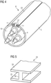
- figure 1 is also the alternative, ready-made submarine cable 6 'according to the invention in a second embodiment figure 4 shown schematically. It can be seen that a closure band 23 drawn in with dashed lines at the beginning of the closing area 18e of the cable protection tube 5 in the separating slot 12 (see 2 ) between the two longitudinal edges 11 (see 2 ) of the cable protection tube 5 is introduced. Further details on this fastener tape 23 have already been mentioned in the general description and will become more detailed below Figures 4 and 5 described in more detail.
- figure 2 shows an enlarged detailed representation of the device 1 according to the invention in the opening area 18b and holding area 18c of the cable protection tube 5 of the submarine cable 6, 6' according to the invention.
- the conductors 4 are inserted in the conveying direction 13 from above into the insertion area 18d into the insertion opening 16 of the protective cable tube 5 .
- a knife 14 is arranged in the conveying direction 10 downstream of the conveyor belt 3b in the upper area of the jacket of the cable protection pipe 5, with the knife 14 cutting open the cable protection pipe 5 and thus the separating slot 12 with two opposite longitudinal edges 11 are formed on the cable protection tube 5.
- a wedge 15 is arranged downstream of the blade 14 in the conveying direction 10, the wedge 15 keeping the separating slot 12 open by resting against the opposite longitudinal edges 11 of the protective cable tube 5.
- the separating slot 12 is held open by the wedge 15 until the conductors 4 are completely inserted in the conveying direction 13 via the insertion opening 16 into the interior of the cable protection tube 5 in the.
- the four inner guide rollers 17 in the interior 16 of the cable protection tube 5 are used to hold down and, if necessary, keep the opened cable protection tube 5 open and, if necessary, to keep the conductor 4 at a distance from the bottom of the cable protection tube 5 in the area where the cable is opened and kept open - protective tube 5.
- FIG 3 now shows the ready-made submarine cable 6 according to the invention in a first embodiment with a slotted cable protection tube 5, in which the electrical and/or optical conductors 4 are accommodated within an optional embedding layer 19.
- the diameter of the cable protection tube 5 before cutting is therefore larger than the diameter of the cable protection tube 5 after closing.
- An overlapping space 22 is then formed between the two casing angle strips 21, in which the embedding layer or another connecting and sealing compound can then be introduced.
- the two casing angle strips 21 can also be welded to one another from the outside as an alternative or in addition.
- figure 4 shows the ready-made submarine cable 6 'according to the invention in a second embodiment with a flexible H-shaped fastener tape 23, which in the separating slot 12 between the two longitudinal edges 11 of the cable protection tube 5 in particular over the entire length of the cable protection tube 5 is inserted in particular in a clamping manner and glued in there via an adhesive layer 27 .
- figure 5 shows the H-shaped fastener tape 23 after figure 4
- the dimensions of the two parallel legs 24, 25 and the intermediate web 26 depend on the diameter and the wall thickness of the cable protection tube 5, the thickness and Surface of the adhesive layer 27, ( 4 ) and the adhesive strength of the adhesive of the adhesive layer 27 ( 4 ) away.
- the fastening strip 23 is inserted into the separating slot 12 of the cable protection tube 5 in such a way that the two parallel legs 24 of the fastening strip 23 run in the circumferential direction of the cable protection tube 5 and are applied to the jacket of the cable protection tube 5 and that the intermediate web 26 of the closure band 23 runs in the radial direction of the cable protection tube 5 and is applied between the surfaces of the two longitudinal edges 11 of the cable protection tube 5, if necessary with a slight circumferential clamping force.
Landscapes
- Engineering & Computer Science (AREA)
- Manufacturing & Machinery (AREA)
- Physics & Mathematics (AREA)
- General Physics & Mathematics (AREA)
- Optics & Photonics (AREA)
- Laying Of Electric Cables Or Lines Outside (AREA)
- Electric Cable Installation (AREA)
Applications Claiming Priority (2)
| Application Number | Priority Date | Filing Date | Title |
|---|---|---|---|
| DE102014203223.7A DE102014203223A1 (de) | 2014-02-24 | 2014-02-24 | Verfahren und Vorrichtung zur Herstellung eines Seekabels sowie damit hergestelltes Seekabel |
| PCT/EP2015/052168 WO2015124418A1 (de) | 2014-02-24 | 2015-02-03 | Verfahren und vorrichtung zur herstellung eines seekabels sowie damit hergestelltes seekabel |
Publications (2)
| Publication Number | Publication Date |
|---|---|
| EP3058632A1 EP3058632A1 (de) | 2016-08-24 |
| EP3058632B1 true EP3058632B1 (de) | 2022-03-02 |
Family
ID=52469814
Family Applications (1)
| Application Number | Title | Priority Date | Filing Date |
|---|---|---|---|
| EP15704246.6A Active EP3058632B1 (de) | 2014-02-24 | 2015-02-03 | Verfahren und vorrichtung zur herstellung eines seekabels sowie damit hergestelltes seekabel |
Country Status (7)
| Country | Link |
|---|---|
| US (1) | US10269471B2 (pl) |
| EP (1) | EP3058632B1 (pl) |
| CN (1) | CN106030944B (pl) |
| DE (1) | DE102014203223A1 (pl) |
| DK (1) | DK3058632T3 (pl) |
| PL (1) | PL3058632T3 (pl) |
| WO (1) | WO2015124418A1 (pl) |
Families Citing this family (11)
| Publication number | Priority date | Publication date | Assignee | Title |
|---|---|---|---|---|
| DE102014206000A1 (de) * | 2014-03-31 | 2015-10-01 | Siemens Aktiengesellschaft | Kühlvorrichtung |
| US11853916B2 (en) * | 2018-05-30 | 2023-12-26 | City Universtiy Of Hong Kong | System and method for determining optimal path arrangements for an infrastructure link with two or more design levels |
| CN109300602B (zh) * | 2018-11-16 | 2024-08-09 | 唐山华通特种线缆制造有限公司 | 一种预埋型复合管缆及其制作方法 |
| CN110481064B (zh) * | 2019-09-27 | 2024-09-24 | 英喜电气(上海)有限公司 | 叶片后缘补胶设备 |
| US11740425B2 (en) * | 2019-10-23 | 2023-08-29 | Corning Research & Development Corporation | Multifiber invisible optical drop cable and methods for routing optical fibers within a multi-dwelling unit |
| US20210159686A1 (en) * | 2019-11-22 | 2021-05-27 | II Elmer Kastelic | Open Heat Shrink Device |
| KR102724220B1 (ko) * | 2019-12-26 | 2024-10-30 | 엘에스전선 주식회사 | 해저케이블 연합장치 |
| DE102020106275A1 (de) * | 2020-03-09 | 2021-09-09 | Rwe Renewables Gmbh | Seekabel für Verlegung auf Gewässerboden |
| CN111725768B (zh) * | 2020-07-07 | 2021-09-14 | 赣州奥鑫新型建材有限公司 | 一种复合材料电缆保护管及其制备方法 |
| CN112310919B (zh) * | 2020-11-25 | 2021-11-05 | 国网山东省电力公司广饶县供电公司 | 一种架空电缆保护装置及其施工方法 |
| CN117219332B (zh) * | 2023-07-28 | 2025-07-29 | 中天科技海缆股份有限公司 | 一种多芯海底电缆及其制作装置 |
Family Cites Families (29)
| Publication number | Priority date | Publication date | Assignee | Title |
|---|---|---|---|---|
| US1185014A (en) * | 1915-01-27 | 1916-05-30 | Charles T Hughes | Plate-joint, clamping-bar therefor, and process of making said joint. |
| US3040121A (en) * | 1959-08-26 | 1962-06-19 | George W Gillemot | Cable splice closure |
| DE2456676A1 (de) * | 1974-11-30 | 1976-08-12 | Kabel Metallwerke Ghh | Elektrisches tiefseekabel |
| CA1048118A (en) * | 1975-05-23 | 1979-02-06 | George W. Gillemot | Re-enterable split splice housing with flexible locking strip |
| DE2651725C2 (de) * | 1976-11-11 | 1978-12-14 | Aeg-Telefunken Kabelwerke Ag, Rheydt, 4050 Moenchengladbach | Verfahren zur Herstellung eines optischen Kabels |
| GB1599998A (en) * | 1977-01-24 | 1981-10-14 | Raychem Ltd | Dimensionally recoverable articles |
| IT1115656B (it) * | 1977-05-04 | 1986-02-03 | Pirelli | Metodo di produzione di elementi componenti cavi di telecomunicazione e impianto atto a realizzarlo |
| DE2743260C2 (de) * | 1977-09-26 | 1990-05-31 | kabelmetal electro GmbH, 3000 Hannover | Nachrichtenkabel mit Lichtwellenleitern und Verfahren zu seiner Herstellung |
| DE3009078C2 (de) * | 1980-03-10 | 1983-01-20 | Siemens AG, 1000 Berlin und 8000 München | Längsgeteilte Kabelmuffe aus schrumpfbarem Material |
| US4413656A (en) * | 1980-09-13 | 1983-11-08 | Raychem Limited | Wrap-around device |
| US4437789A (en) * | 1981-09-24 | 1984-03-20 | Gk Technologies, Incorporated | Method and means for protecting buried cable from rodent damage |
| US4741470A (en) * | 1983-05-24 | 1988-05-03 | Olin Corporation | Method for assembling an optical fiber communication cable |
| JPH0443674Y2 (pl) * | 1987-02-09 | 1992-10-15 | ||
| US4777072A (en) * | 1987-02-24 | 1988-10-11 | Cason Jr Claude | Pliable sheet and coupling strip |
| US5054881A (en) | 1988-12-20 | 1991-10-08 | Gte Northwest Incorporated | Submarine fiber optic cable assembly |
| FR2655765B1 (fr) | 1989-12-13 | 1994-07-22 | Lens Cableries | Cable pour ligne electrique aerienne de transport d'energie, et procedes et dispositifs de fabrication d'un tel cable. |
| WO1997010461A1 (en) * | 1995-09-13 | 1997-03-20 | Regional Fabricators, Inc. | Ocean bottom cable handling system |
| CN1162823A (zh) | 1996-01-24 | 1997-10-22 | 西门子公司 | 一种电缆的生产方法和设备 |
| US5647358A (en) * | 1996-03-20 | 1997-07-15 | Vilasi; Joseph | Expandable inter vivos tube |
| US6410848B1 (en) * | 1999-04-30 | 2002-06-25 | The Zippertubing Company | Heat shrinkable side entry cable jacket |
| DE19927958C2 (de) * | 1999-06-18 | 2002-01-31 | Schlemmer Gmbh | Verfahren zur Herstellung eines Wellrohres mit einer längs einer Mantellinie verlaufenden schlitzförmigen Öffnung |
| AU2002326521A1 (en) * | 2001-08-09 | 2003-02-24 | Federal-Mogul Powertrain, Inc. | Damped flexible protective sleeving |
| DE102006062545B4 (de) * | 2006-12-29 | 2008-09-18 | Flexa Gmbh & Co. Produktion Und Vertrieb Kg | Hilfswerkzeug, Set mit einem Hilfswerkzeug, einem Schutzschlauch sowie einem Verschlusselement und Anordnung mit einem Vorrat eines Schutzschlauchs sowie einem Hilfswerkzeug |
| GB2462264A (en) * | 2008-07-30 | 2010-02-03 | Tyco Electronics Ltd Uk | Cable assembly |
| US8026442B2 (en) * | 2009-06-15 | 2011-09-27 | Southwire Company | Flexible cable with structurally enhanced outer sheath |
| CN202627339U (zh) | 2012-04-24 | 2012-12-26 | 品诚塑胶科技(上海)有限公司 | H型连接件 |
| EP2736306A1 (de) * | 2012-11-22 | 2014-05-28 | Siemens Aktiengesellschaft | Herstellungsvorrichtung und Verfahren zur Herstellung einer Induktionsvorrichtung für die Erwärmung eines Schwerölreservoirs sowie Induktionsvorrichtung für die Erwärmung eines Schwerölreservoirs |
| US9224519B2 (en) * | 2012-12-13 | 2015-12-29 | Tyco Electronics Corporation | Holdout devices and cover assemblies and methods incorporating the same |
| CN103021585B (zh) | 2012-12-31 | 2015-05-20 | 上海斯麟特种设备工程有限公司 | 一种旋转曲面联锁铠装电缆制造设备 |
-
2014
- 2014-02-24 DE DE102014203223.7A patent/DE102014203223A1/de not_active Ceased
-
2015
- 2015-02-03 PL PL15704246.6T patent/PL3058632T3/pl unknown
- 2015-02-03 DK DK15704246.6T patent/DK3058632T3/da active
- 2015-02-03 WO PCT/EP2015/052168 patent/WO2015124418A1/de not_active Ceased
- 2015-02-03 US US15/108,698 patent/US10269471B2/en active Active
- 2015-02-03 CN CN201580010218.8A patent/CN106030944B/zh not_active Expired - Fee Related
- 2015-02-03 EP EP15704246.6A patent/EP3058632B1/de active Active
Also Published As
| Publication number | Publication date |
|---|---|
| CN106030944A (zh) | 2016-10-12 |
| DK3058632T3 (da) | 2022-04-19 |
| PL3058632T3 (pl) | 2022-07-25 |
| CN106030944B (zh) | 2019-07-26 |
| DE102014203223A1 (de) | 2015-08-27 |
| WO2015124418A1 (de) | 2015-08-27 |
| US10269471B2 (en) | 2019-04-23 |
| US20160358697A1 (en) | 2016-12-08 |
| EP3058632A1 (de) | 2016-08-24 |
Similar Documents
| Publication | Publication Date | Title |
|---|---|---|
| EP3058632B1 (de) | Verfahren und vorrichtung zur herstellung eines seekabels sowie damit hergestelltes seekabel | |
| DE69318291T2 (de) | Verfahren und einrichtung zur herstellung eines verbindungskabels | |
| DE2743260C2 (de) | Nachrichtenkabel mit Lichtwellenleitern und Verfahren zu seiner Herstellung | |
| DE2449439C3 (de) | Nachrichtenkabel mit Lichtleiter bzw. Lichtleiterbündel als Übertragungselemente | |
| DE112015002173B4 (de) | Herstellungsverfahren für eine optische Äquipotential-Fasereinheit für photoelektrische Hochspannungs-Kompositkabel | |
| EP3158614A1 (de) | Wellrohr aus kunststoff zum ummanteln von leitungen sowie verfahren zur herstellung eines solchen wellrohres | |
| DE2903012C2 (de) | Lichtleiterbandkabel-Element | |
| EP3984106B1 (de) | Kompakte leitungsführung für reinraumanwendungen, sowie herstellverfahren und hülleinheit hierfür | |
| EP3312956A1 (de) | Verfahren und vorrichtung zum abisolieren eines kabels mit einer mehrschichtigen ummantelung | |
| DE2735476C2 (de) | Verfahren und Vorrichtung zur Herstellung von Kabeln und Leitungen mit SZ-verseilten Verseilelementen | |
| EP3007179A1 (de) | Kabel hoher steifigkeit und verfahren zu seiner herstellung | |
| DE69738251T2 (de) | Optisches Kabel mit rohrenförmiger metallischer Seele | |
| DE60206657T2 (de) | Verfahren zum installieren eines hoch- oder mittelleistungskabels im boden | |
| DE3803318A1 (de) | Verfahren und vorrichtung zum abschnittsweisen ummanteln von objekten mit kunststoff | |
| DE102010017147A1 (de) | Verfahren zur Herstellung eines Rohrverbunds | |
| EP0251252B1 (de) | Zusatzbewehrung für Kabel | |
| DE102015106307B4 (de) | Vorrichtung und Verfahren zum Konfektionieren einer Energieführungskette | |
| DE3803777C2 (de) | Vorrichtung zum Abschließen und Abdichten des freien Endes eines Kabelführungsrohres | |
| EP0842716A2 (de) | Verfahren und Vorrichtung zur Herstellung von Metallröhrchen grosser Länge | |
| EP2985133B1 (de) | Verfahren zur nachumhüllung eines rohrformteils | |
| DE2434600C2 (de) | Kabelmuffe für Spleißverbindungen | |
| DE4440507A1 (de) | Elektrisches Kabel zur Übertragung von Daten | |
| DE893526C (de) | Einrichtung zum Herstellen von spiraligen Huellen aus thermoplastisch verformbaren Folienstreifen fuer elektrische Leiter | |
| DE102014200874B4 (de) | Verfahren und Anlage zur Herstellung eines konfektionierten Kabels vorbestimmter Länge | |
| DE4228271A1 (de) | Verfahren und Einrichtung zur Herstellung eines optischen Kabels |
Legal Events
| Date | Code | Title | Description |
|---|---|---|---|
| PUAI | Public reference made under article 153(3) epc to a published international application that has entered the european phase |
Free format text: ORIGINAL CODE: 0009012 |
|
| 17P | Request for examination filed |
Effective date: 20160520 |
|
| AK | Designated contracting states |
Kind code of ref document: A1 Designated state(s): AL AT BE BG CH CY CZ DE DK EE ES FI FR GB GR HR HU IE IS IT LI LT LU LV MC MK MT NL NO PL PT RO RS SE SI SK SM TR |
|
| AX | Request for extension of the european patent |
Extension state: BA ME |
|
| STAA | Information on the status of an ep patent application or granted ep patent |
Free format text: STATUS: EXAMINATION IS IN PROGRESS |
|
| DAX | Request for extension of the european patent (deleted) | ||
| 17Q | First examination report despatched |
Effective date: 20170517 |
|
| RAP1 | Party data changed (applicant data changed or rights of an application transferred) |
Owner name: SIEMENS AKTIENGESELLSCHAFT |
|
| RAP1 | Party data changed (applicant data changed or rights of an application transferred) |
Owner name: SIEMENS GAMESA RENEWABLE ENERGY A/S |
|
| REG | Reference to a national code |
Ref country code: DE Ref legal event code: R079 Ref document number: 502015015673 Country of ref document: DE Free format text: PREVIOUS MAIN CLASS: H02G0001100000 Ipc: G02B0006440000 |
|
| RIC1 | Information provided on ipc code assigned before grant |
Ipc: G02B 6/44 20060101AFI20210722BHEP Ipc: H01B 7/14 20060101ALI20210722BHEP Ipc: H01B 13/26 20060101ALI20210722BHEP Ipc: H02G 9/06 20060101ALI20210722BHEP Ipc: H02G 1/10 20060101ALI20210722BHEP |
|
| GRAP | Despatch of communication of intention to grant a patent |
Free format text: ORIGINAL CODE: EPIDOSNIGR1 |
|
| STAA | Information on the status of an ep patent application or granted ep patent |
Free format text: STATUS: GRANT OF PATENT IS INTENDED |
|
| INTG | Intention to grant announced |
Effective date: 20211015 |
|
| GRAS | Grant fee paid |
Free format text: ORIGINAL CODE: EPIDOSNIGR3 |
|
| GRAA | (expected) grant |
Free format text: ORIGINAL CODE: 0009210 |
|
| STAA | Information on the status of an ep patent application or granted ep patent |
Free format text: STATUS: THE PATENT HAS BEEN GRANTED |
|
| AK | Designated contracting states |
Kind code of ref document: B1 Designated state(s): AL AT BE BG CH CY CZ DE DK EE ES FI FR GB GR HR HU IE IS IT LI LT LU LV MC MK MT NL NO PL PT RO RS SE SI SK SM TR |
|
| REG | Reference to a national code |
Ref country code: GB Ref legal event code: FG4D Free format text: NOT ENGLISH |
|
| REG | Reference to a national code |
Ref country code: CH Ref legal event code: EP Ref country code: AT Ref legal event code: REF Ref document number: 1472729 Country of ref document: AT Kind code of ref document: T Effective date: 20220315 |
|
| REG | Reference to a national code |
Ref country code: DE Ref legal event code: R096 Ref document number: 502015015673 Country of ref document: DE |
|
| REG | Reference to a national code |
Ref country code: IE Ref legal event code: FG4D Free format text: LANGUAGE OF EP DOCUMENT: GERMAN |
|
| REG | Reference to a national code |
Ref country code: DK Ref legal event code: T3 Effective date: 20220411 |
|
| REG | Reference to a national code |
Ref country code: NL Ref legal event code: FP |
|
| REG | Reference to a national code |
Ref country code: LT Ref legal event code: MG9D |
|
| PG25 | Lapsed in a contracting state [announced via postgrant information from national office to epo] |
Ref country code: SE Free format text: LAPSE BECAUSE OF FAILURE TO SUBMIT A TRANSLATION OF THE DESCRIPTION OR TO PAY THE FEE WITHIN THE PRESCRIBED TIME-LIMIT Effective date: 20220302 Ref country code: RS Free format text: LAPSE BECAUSE OF FAILURE TO SUBMIT A TRANSLATION OF THE DESCRIPTION OR TO PAY THE FEE WITHIN THE PRESCRIBED TIME-LIMIT Effective date: 20220302 Ref country code: NO Free format text: LAPSE BECAUSE OF FAILURE TO SUBMIT A TRANSLATION OF THE DESCRIPTION OR TO PAY THE FEE WITHIN THE PRESCRIBED TIME-LIMIT Effective date: 20220602 Ref country code: LT Free format text: LAPSE BECAUSE OF FAILURE TO SUBMIT A TRANSLATION OF THE DESCRIPTION OR TO PAY THE FEE WITHIN THE PRESCRIBED TIME-LIMIT Effective date: 20220302 Ref country code: HR Free format text: LAPSE BECAUSE OF FAILURE TO SUBMIT A TRANSLATION OF THE DESCRIPTION OR TO PAY THE FEE WITHIN THE PRESCRIBED TIME-LIMIT Effective date: 20220302 Ref country code: ES Free format text: LAPSE BECAUSE OF FAILURE TO SUBMIT A TRANSLATION OF THE DESCRIPTION OR TO PAY THE FEE WITHIN THE PRESCRIBED TIME-LIMIT Effective date: 20220302 Ref country code: BG Free format text: LAPSE BECAUSE OF FAILURE TO SUBMIT A TRANSLATION OF THE DESCRIPTION OR TO PAY THE FEE WITHIN THE PRESCRIBED TIME-LIMIT Effective date: 20220602 |
|
| REG | Reference to a national code |
Ref country code: DE Ref legal event code: R082 Ref document number: 502015015673 Country of ref document: DE Representative=s name: SAUTHOFF, KARSTEN, DIPL.-ING. UNIV., DE |
|
| PG25 | Lapsed in a contracting state [announced via postgrant information from national office to epo] |
Ref country code: LV Free format text: LAPSE BECAUSE OF FAILURE TO SUBMIT A TRANSLATION OF THE DESCRIPTION OR TO PAY THE FEE WITHIN THE PRESCRIBED TIME-LIMIT Effective date: 20220302 Ref country code: GR Free format text: LAPSE BECAUSE OF FAILURE TO SUBMIT A TRANSLATION OF THE DESCRIPTION OR TO PAY THE FEE WITHIN THE PRESCRIBED TIME-LIMIT Effective date: 20220603 Ref country code: FI Free format text: LAPSE BECAUSE OF FAILURE TO SUBMIT A TRANSLATION OF THE DESCRIPTION OR TO PAY THE FEE WITHIN THE PRESCRIBED TIME-LIMIT Effective date: 20220302 |
|
| PG25 | Lapsed in a contracting state [announced via postgrant information from national office to epo] |
Ref country code: SM Free format text: LAPSE BECAUSE OF FAILURE TO SUBMIT A TRANSLATION OF THE DESCRIPTION OR TO PAY THE FEE WITHIN THE PRESCRIBED TIME-LIMIT Effective date: 20220302 Ref country code: SK Free format text: LAPSE BECAUSE OF FAILURE TO SUBMIT A TRANSLATION OF THE DESCRIPTION OR TO PAY THE FEE WITHIN THE PRESCRIBED TIME-LIMIT Effective date: 20220302 Ref country code: RO Free format text: LAPSE BECAUSE OF FAILURE TO SUBMIT A TRANSLATION OF THE DESCRIPTION OR TO PAY THE FEE WITHIN THE PRESCRIBED TIME-LIMIT Effective date: 20220302 Ref country code: PT Free format text: LAPSE BECAUSE OF FAILURE TO SUBMIT A TRANSLATION OF THE DESCRIPTION OR TO PAY THE FEE WITHIN THE PRESCRIBED TIME-LIMIT Effective date: 20220704 Ref country code: EE Free format text: LAPSE BECAUSE OF FAILURE TO SUBMIT A TRANSLATION OF THE DESCRIPTION OR TO PAY THE FEE WITHIN THE PRESCRIBED TIME-LIMIT Effective date: 20220302 Ref country code: CZ Free format text: LAPSE BECAUSE OF FAILURE TO SUBMIT A TRANSLATION OF THE DESCRIPTION OR TO PAY THE FEE WITHIN THE PRESCRIBED TIME-LIMIT Effective date: 20220302 |
|
| PG25 | Lapsed in a contracting state [announced via postgrant information from national office to epo] |
Ref country code: IS Free format text: LAPSE BECAUSE OF FAILURE TO SUBMIT A TRANSLATION OF THE DESCRIPTION OR TO PAY THE FEE WITHIN THE PRESCRIBED TIME-LIMIT Effective date: 20220702 Ref country code: AL Free format text: LAPSE BECAUSE OF FAILURE TO SUBMIT A TRANSLATION OF THE DESCRIPTION OR TO PAY THE FEE WITHIN THE PRESCRIBED TIME-LIMIT Effective date: 20220302 |
|
| REG | Reference to a national code |
Ref country code: DE Ref legal event code: R097 Ref document number: 502015015673 Country of ref document: DE |
|
| PLBE | No opposition filed within time limit |
Free format text: ORIGINAL CODE: 0009261 |
|
| STAA | Information on the status of an ep patent application or granted ep patent |
Free format text: STATUS: NO OPPOSITION FILED WITHIN TIME LIMIT |
|
| 26N | No opposition filed |
Effective date: 20221205 |
|
| PG25 | Lapsed in a contracting state [announced via postgrant information from national office to epo] |
Ref country code: SI Free format text: LAPSE BECAUSE OF FAILURE TO SUBMIT A TRANSLATION OF THE DESCRIPTION OR TO PAY THE FEE WITHIN THE PRESCRIBED TIME-LIMIT Effective date: 20220302 |
|
| PG25 | Lapsed in a contracting state [announced via postgrant information from national office to epo] |
Ref country code: IT Free format text: LAPSE BECAUSE OF FAILURE TO SUBMIT A TRANSLATION OF THE DESCRIPTION OR TO PAY THE FEE WITHIN THE PRESCRIBED TIME-LIMIT Effective date: 20220302 |
|
| PG25 | Lapsed in a contracting state [announced via postgrant information from national office to epo] |
Ref country code: MC Free format text: LAPSE BECAUSE OF FAILURE TO SUBMIT A TRANSLATION OF THE DESCRIPTION OR TO PAY THE FEE WITHIN THE PRESCRIBED TIME-LIMIT Effective date: 20220302 |
|
| REG | Reference to a national code |
Ref country code: CH Ref legal event code: PL |
|
| REG | Reference to a national code |
Ref country code: BE Ref legal event code: MM Effective date: 20230228 |
|
| PG25 | Lapsed in a contracting state [announced via postgrant information from national office to epo] |
Ref country code: LU Free format text: LAPSE BECAUSE OF NON-PAYMENT OF DUE FEES Effective date: 20230203 Ref country code: LI Free format text: LAPSE BECAUSE OF NON-PAYMENT OF DUE FEES Effective date: 20230228 Ref country code: CH Free format text: LAPSE BECAUSE OF NON-PAYMENT OF DUE FEES Effective date: 20230228 |
|
| PG25 | Lapsed in a contracting state [announced via postgrant information from national office to epo] |
Ref country code: BE Free format text: LAPSE BECAUSE OF NON-PAYMENT OF DUE FEES Effective date: 20230228 |
|
| REG | Reference to a national code |
Ref country code: AT Ref legal event code: MM01 Ref document number: 1472729 Country of ref document: AT Kind code of ref document: T Effective date: 20230203 |
|
| PGFP | Annual fee paid to national office [announced via postgrant information from national office to epo] |
Ref country code: IE Payment date: 20240216 Year of fee payment: 10 Ref country code: NL Payment date: 20240220 Year of fee payment: 10 |
|
| PG25 | Lapsed in a contracting state [announced via postgrant information from national office to epo] |
Ref country code: AT Free format text: LAPSE BECAUSE OF NON-PAYMENT OF DUE FEES Effective date: 20230203 |
|
| PG25 | Lapsed in a contracting state [announced via postgrant information from national office to epo] |
Ref country code: AT Free format text: LAPSE BECAUSE OF NON-PAYMENT OF DUE FEES Effective date: 20230203 |
|
| PGFP | Annual fee paid to national office [announced via postgrant information from national office to epo] |
Ref country code: DE Payment date: 20240216 Year of fee payment: 10 Ref country code: GB Payment date: 20240222 Year of fee payment: 10 |
|
| PGFP | Annual fee paid to national office [announced via postgrant information from national office to epo] |
Ref country code: PL Payment date: 20240126 Year of fee payment: 10 Ref country code: FR Payment date: 20240221 Year of fee payment: 10 Ref country code: DK Payment date: 20240221 Year of fee payment: 10 |
|
| PG25 | Lapsed in a contracting state [announced via postgrant information from national office to epo] |
Ref country code: CY Free format text: LAPSE BECAUSE OF FAILURE TO SUBMIT A TRANSLATION OF THE DESCRIPTION OR TO PAY THE FEE WITHIN THE PRESCRIBED TIME-LIMIT; INVALID AB INITIO Effective date: 20150203 |
|
| PG25 | Lapsed in a contracting state [announced via postgrant information from national office to epo] |
Ref country code: HU Free format text: LAPSE BECAUSE OF FAILURE TO SUBMIT A TRANSLATION OF THE DESCRIPTION OR TO PAY THE FEE WITHIN THE PRESCRIBED TIME-LIMIT; INVALID AB INITIO Effective date: 20150203 |
|
| REG | Reference to a national code |
Ref country code: DE Ref legal event code: R119 Ref document number: 502015015673 Country of ref document: DE |
|
| REG | Reference to a national code |
Ref country code: DK Ref legal event code: EBP Effective date: 20250228 |
|
| REG | Reference to a national code |
Ref country code: NL Ref legal event code: MM Effective date: 20250301 |
|
| GBPC | Gb: european patent ceased through non-payment of renewal fee |
Effective date: 20250203 |
|
| PG25 | Lapsed in a contracting state [announced via postgrant information from national office to epo] |
Ref country code: NL Free format text: LAPSE BECAUSE OF NON-PAYMENT OF DUE FEES Effective date: 20250301 |
|
| PG25 | Lapsed in a contracting state [announced via postgrant information from national office to epo] |
Ref country code: TR Free format text: LAPSE BECAUSE OF FAILURE TO SUBMIT A TRANSLATION OF THE DESCRIPTION OR TO PAY THE FEE WITHIN THE PRESCRIBED TIME-LIMIT Effective date: 20220302 |
|
| PG25 | Lapsed in a contracting state [announced via postgrant information from national office to epo] |
Ref country code: DE Free format text: LAPSE BECAUSE OF NON-PAYMENT OF DUE FEES Effective date: 20250902 |
|
| PG25 | Lapsed in a contracting state [announced via postgrant information from national office to epo] |
Ref country code: GB Free format text: LAPSE BECAUSE OF NON-PAYMENT OF DUE FEES Effective date: 20250203 |
|
| PG25 | Lapsed in a contracting state [announced via postgrant information from national office to epo] |
Ref country code: DK Free format text: LAPSE BECAUSE OF NON-PAYMENT OF DUE FEES Effective date: 20250228 |
|
| PG25 | Lapsed in a contracting state [announced via postgrant information from national office to epo] |
Ref country code: FR Free format text: LAPSE BECAUSE OF NON-PAYMENT OF DUE FEES Effective date: 20250228 |
|
| PG25 | Lapsed in a contracting state [announced via postgrant information from national office to epo] |
Ref country code: IE Free format text: LAPSE BECAUSE OF NON-PAYMENT OF DUE FEES Effective date: 20250203 |
|
| PG25 | Lapsed in a contracting state [announced via postgrant information from national office to epo] |
Ref country code: PL Free format text: LAPSE BECAUSE OF NON-PAYMENT OF DUE FEES Effective date: 20250203 |