EP3059122A1 - Dispositif, en particulier moyen de signalement destine a etre monte sur une vitre de vehicule - Google Patents
Dispositif, en particulier moyen de signalement destine a etre monte sur une vitre de vehicule Download PDFInfo
- Publication number
- EP3059122A1 EP3059122A1 EP16000377.8A EP16000377A EP3059122A1 EP 3059122 A1 EP3059122 A1 EP 3059122A1 EP 16000377 A EP16000377 A EP 16000377A EP 3059122 A1 EP3059122 A1 EP 3059122A1
- Authority
- EP
- European Patent Office
- Prior art keywords
- vehicle
- signal element
- signal
- holder
- operating element
- Prior art date
- Legal status (The legal status is an assumption and is not a legal conclusion. Google has not performed a legal analysis and makes no representation as to the accuracy of the status listed.)
- Withdrawn
Links
Images

Classifications
-
- B—PERFORMING OPERATIONS; TRANSPORTING
- B60—VEHICLES IN GENERAL
- B60Q—ARRANGEMENT OF SIGNALLING OR LIGHTING DEVICES, THE MOUNTING OR SUPPORTING THEREOF OR CIRCUITS THEREFOR, FOR VEHICLES IN GENERAL
- B60Q1/00—Arrangement of optical signalling or lighting devices, the mounting or supporting thereof or circuits therefor
- B60Q1/26—Arrangement of optical signalling or lighting devices, the mounting or supporting thereof or circuits therefor the devices being primarily intended to indicate the vehicle, or parts thereof, or to give signals, to other traffic
- B60Q1/2661—Arrangement of optical signalling or lighting devices, the mounting or supporting thereof or circuits therefor the devices being primarily intended to indicate the vehicle, or parts thereof, or to give signals, to other traffic mounted on parts having other functions
- B60Q1/268—Arrangement of optical signalling or lighting devices, the mounting or supporting thereof or circuits therefor the devices being primarily intended to indicate the vehicle, or parts thereof, or to give signals, to other traffic mounted on parts having other functions on windscreens or windows
-
- B—PERFORMING OPERATIONS; TRANSPORTING
- B60—VEHICLES IN GENERAL
- B60Q—ARRANGEMENT OF SIGNALLING OR LIGHTING DEVICES, THE MOUNTING OR SUPPORTING THEREOF OR CIRCUITS THEREFOR, FOR VEHICLES IN GENERAL
- B60Q1/00—Arrangement of optical signalling or lighting devices, the mounting or supporting thereof or circuits therefor
- B60Q1/26—Arrangement of optical signalling or lighting devices, the mounting or supporting thereof or circuits therefor the devices being primarily intended to indicate the vehicle, or parts thereof, or to give signals, to other traffic
- B60Q1/50—Arrangement of optical signalling or lighting devices, the mounting or supporting thereof or circuits therefor the devices being primarily intended to indicate the vehicle, or parts thereof, or to give signals, to other traffic for indicating other intentions or conditions, e.g. request for waiting or overtaking
- B60Q1/52—Arrangement of optical signalling or lighting devices, the mounting or supporting thereof or circuits therefor the devices being primarily intended to indicate the vehicle, or parts thereof, or to give signals, to other traffic for indicating other intentions or conditions, e.g. request for waiting or overtaking for indicating emergencies
Definitions
- the invention relates to a device, in particular a signal means for attachment to a vehicle window according to the preamble of claim 1.
- Spacers are known which are attached to a side of the vehicle facing the roadway in order to mark an area in which the persons can move.
- these devices are expensive to install, as well as bulky and thus unsuitable for carrying in a vehicle.
- the invention is therefore based on the object to provide a device with a simple way a stagnant vehicle is kenn Hanbar.
- the device has at least one signal element and at least one operating element, wherein the signal element is inflatable.
- the device having the signal element can be attached to the vehicle from the vehicle, both on the driver side and on the passenger side. For this the driver does not need to leave the vehicle.
- the device is not limited to the application for marking of passenger cars, but it can also be used for the identification of trucks or motorcycles.
- the device can easily be stowed in the vehicle after or before use without occupying significant space.
- the inflation of the signal element is preferably carried out while the device is at least partially held out of the window.
- About the control of the vehicle occupant can control the device, in particular to initiate the inflation process.
- the vehicle occupant does not need to leave the vehicle to identify the vehicle by the erfindungsgenzeße device and poses no additional danger.
- the invention may further provide that the signal element is associated with an operating element, in particular permanently assigned, by which the signal element can be controlled, in particular the operating element fixing means, preferably having a circumferential rubber lip.
- the control element can be fixed to the vehicle window. So that the vehicle occupant can operate the operating element comfortably without this moving, it can be fixed by the rubber lip or other fixing means from the inside to the vehicle window.
- the invention further provides that the control element is associated with a holder for fastening the device to the body and / or on the vehicle window of the vehicle, in particular pivotally associated and the holder is designed as a clamp, clamp, suction cup, magnet or the like ,
- the vehicle window is slightly opened to clamp the bracket on the window pane.
- the window pane is closed again, so that the holder between Window and door frame is clamped.
- the holder has alternatively magnets, with which the device is attachable to the body of the vehicle.
- the holder can be conveniently attached to the window and the control element at the same time still advantageously aligned for the vehicle occupant, the holder and the control element, preferably by small webs, pivotally connected to each other.
- the control element can be moved parallel to the vehicle window and thus fixate easily by means of the fixing means on the window pane. Regardless of the nature of the holder, it provides the invention that the operating element is positioned in the use of the device within the vehicle, while the signal element is located outside of the vehicle.
- the present invention can further provide that the operating element is associated with an air supply device for inflating the signal element, in particular the air supply device is integrated into the operating element.
- the air supply device may preferably be a blower or a compressed air cartridge.
- the air supply device is connected by an air line, in particular by a hose with the signal element.
- the air supply device, in particular the compressed air cartridge is assigned to a part of the holder, which simultaneously describes the pivot axis of the operating element. Since, accordingly, the air supply device is located inside the vehicle and the signal element to be inflated outside the vehicle, the compressed air is supplied to the signal element through a thin tube, following the shape of the holder, in particular a clip.
- the air supply device is designed as a fan, it can provide the invention that the air is sucked out of the signal element by the fan out again.
- the signal element is associated with a valve which can be opened after use of the device to allow the air to escape.
- the air supply device or the air line is associated with a check valve, so that during the inflation of the signal element or after inflation of the signal element no air can escape through the air line.
- a further preferred embodiment of the present invention provides that the inflated signal element is alignable in a starting position transversely to a longitudinal axis of the vehicle and parallel to a road surface, and preferably protrudes at least partially into a roadway area.
- the signal element is preferably formed in the inflated state as a wedge-shaped triangle, wherein the base of this triangle can be formed transparent.
- the triangle has a height of 50 cm, preferably 80 cm, in particular 1 m. Accordingly, the triangle or the signal element protrudes its height accordingly in the road or points in the direction of the road.
- With the base surface of the triangle touches the vehicle window, while at the same time about a side edge of the base, which is fixedly connected to the holder of the device, is pivotable. By this pivotal assignment of the signal element, it can yield gusts, which are generated for example by subsequent vehicles.
- a retaining means can be assigned to the holder, in particular the operating element, preferably the retaining means can be fastened to the holder or the operating element, in particular can be attached or clipped, in order to pivot the area over which the signal element can pivot about the axis. limit.
- the retaining means causes the signal element is not struck on the vehicle roof in strong gusts. Rather, the retaining means limits the freedom of movement of the signal element, so that the signal efficiency of the device is maintained.
- the retaining means forms with the horizontal approximately at an angle of 10 ° to 30 °, preferably 30 ° to 45 °.
- the present invention can further provide that the signal element reflectors and / or lamps, in particular LEDs are assigned, the LEDs in a continuous and / or flash mode, preferably in different colors are operable and a power supply for the LEDs, such as at least one battery, preferably integrated in the control element and controllable via the control element.
- a power supply for the LEDs such as at least one battery, preferably integrated in the control element and controllable via the control element.
- reflectors on the side of the signal element may be arrow-shaped in order to identify subsequent vehicles on which side the broken-down vehicle is to be overtaken.
- areas on the signal element can be designed to be transparent, in particular as transparent arrows or other warning signs.
- the LEDs which are preferably associated with the operating element, shine through the transparent base part of the signal element into the interior of the signal element and preferably identify transparent areas of the signal element. Depending on the choice of the operating mode of the LEDs thus illuminates the signal in different colors continuous or flash-like.
- the operating mode of the lighting means can be set by the vehicle occupants out of the vehicle via the operating element.
- the control element can also have a socket, via which the light source can be supplied with the 12 volt on-board voltage of the vehicle.
- the invention may further provide that the deflated signal element, the control element and the retaining means are stowed in a pocket, preferably for stowing in the pocket, the unexploded signal element can be wrapped around the operating element and the retaining means. To do this, remove the two brackets of the restraint from the bracket and release a rubber band connecting the two brackets from the brackets. After disassembling the restraint, all elements can be wrapped in the evacuated signal and stowed in the bag.
- a device 10 is used to identify a stowed vehicle 11. It should be expressly understood that the device 10 of the invention is not for use in combination with a car, as in Fig. 1 and 2 is shown limited. Rather, it is provided according to the invention that the device 10 can also be used for trucks or motorcycles.
- the device 10 or a signal element 12 of the device 10 is inflated.
- the signal element 12 extends from a vehicle window 13 (FIG. Fig. 1 ). Trained as a triangle signal element 12 extends so transversely to a longitudinal axis 14 of the vehicle 11 in the direction of the lane area 15.
- the height or the length of the triangular signal element 12 may, depending on the embodiment of the Device 10 vary. As a particularly advantageous length 80 cm or 1 m has been established.
- a side surface 16 of the signal element 12 may be associated with reflectors 17, which are, for example, arrow-shaped ( Fig. 2 ). For subsequent vehicles, these reflectors 17 emerge and refer the following vehicles to the side where the broken-down vehicle 11 is to be overtaken. However, these reflectors 17 may also be formed as transparent partial surfaces of the side surface 16. When the signal element 12 is illuminated from the inside, the transparent partial areas light up brightly.
- the device 10 For fastening the device 10 to the vehicle 11, in particular to the vehicle window 13, the device 10 has a holder 18.
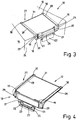
- the holder 18 At the in Fig. 3 illustrated embodiment of the device 10, the holder 18 on two terminals 19, which can be pushed onto the lowered vehicle window 13.
- the vehicle window 13 In order to strengthen the attachment of the device 10, the vehicle window 13 can be closed again, so that the terminals 19 are additionally clamped between the vehicle window 13 and a door frame.
- the holder 18 has no further clamping means, but only between the vehicle window 13 and door frame is clamped.
- a control element 22 is pivotally connected to the terminals 19 via rod-shaped pivoting means 21.
- the control element 22 is used for operation, in particular the control of the device 10 and the signal element 12. For this purpose, it has not shown operating means, such as buttons or switches.
- this has a plurality of LEDs 23.
- These LEDs 23 can be controlled by the operating element 22.
- 22 differently colored LEDs 23 are associated with the control element, which can be operated either continuously or in a flash-like manner.
- the LEDs 23 radiate into the signal element 12 through a transparent base 24 of the triangular signal element 12 and thus illuminate the transparent regions on the side surface 16 of the signal element 12.
- the control element 22 does not slip during operation of the LEDs 23, is the Control element 22 associated with a rubber lip 25, which is intended to fix the control element 22 to the vehicle window 13.
- the open end 20 of the clamp 19 is further associated with an air supply device 26 as an extension of the pivot axis of the pivot means 21.
- This air supply device 26 may be, for example, a fan which blows air into the signal element 12 via an air line or a thin tube (not shown). For discharging the air from the signal element 12, the blower can be operated backwards so that it sucks in air.
- the invention also provides that in the air supply device 26 compressed air cartridges are integrated, which conduct air when using the device 10 via a thin tube in the signal element 12.
- the air supply device 26 is also controlled via the operating element 22.
- the air supply device 26 and / or the control element 22 and the LEDs 23 are batteries that are associated with the air supply device 26 and / or the control element 22.
- the control element 22 is associated with a connection socket, not shown, via which the device 10 can be powered by the 12 volt on-board connection of the vehicle 11.
- the holder 18 is assigned a retaining means 27.
- This retaining means 27 consists of two parallel brackets 28 which are laterally pushed with a first end 29 on the holder 18 and, if appropriate, engage.
- the second ends 30 of the bracket 28 are connected via a connecting means, in particular a rubber band 31 with each other.
- This rubber band 31 is supplied to the two second ends 30 under mechanical tension (residual stress), so that the clamps 28 are held together by the tension of the rubber band 31.
- the brackets 28 describe relative to a horizontal 32 an angle of preferably 30 ° to 60 °.
- the signal element 12 which is preferably made of a plastic bag, is firmly connected to the holder 18.
- the signal element 12th additionally having a valve that can be manually opened by the vehicle occupant.
- the air is discharged from the signal element 12, the rubber band 31 removed from the bracket 28, the bracket 28 is pulled from the bracket 18 and rolled together with the bracket 18 and the control element 22 in the signal element 12, then in a Bag to be stowed.
Landscapes
- Engineering & Computer Science (AREA)
- Mechanical Engineering (AREA)
- Lighting Device Outwards From Vehicle And Optical Signal (AREA)
Applications Claiming Priority (1)
| Application Number | Priority Date | Filing Date | Title |
|---|---|---|---|
| DE102015001898.1A DE102015001898A1 (de) | 2015-02-18 | 2015-02-18 | Vorrichtung, insbesondere Signalmittel zum Anbringen an eine Fahrzeugscheibe |
Publications (1)
| Publication Number | Publication Date |
|---|---|
| EP3059122A1 true EP3059122A1 (fr) | 2016-08-24 |
Family
ID=55409665
Family Applications (1)
| Application Number | Title | Priority Date | Filing Date |
|---|---|---|---|
| EP16000377.8A Withdrawn EP3059122A1 (fr) | 2015-02-18 | 2016-02-16 | Dispositif, en particulier moyen de signalement destine a etre monte sur une vitre de vehicule |
Country Status (2)
| Country | Link |
|---|---|
| EP (1) | EP3059122A1 (fr) |
| DE (1) | DE102015001898A1 (fr) |
Cited By (3)
| Publication number | Priority date | Publication date | Assignee | Title |
|---|---|---|---|---|
| DE102016014025A1 (de) | 2016-11-24 | 2017-08-17 | Daimler Ag | Warnvorrichtung zum automatischen Aufstellen eines Warnsignalelements, insbesondere Warndreiecks |
| IL261288A (en) * | 2016-03-21 | 2018-10-31 | Moshe Kilim | Standing car warning system |
| GB2629780A (en) * | 2023-05-09 | 2024-11-13 | Car Love Heart Ltd | Vehicle protection and visibility enhancement |
Citations (7)
| Publication number | Priority date | Publication date | Assignee | Title |
|---|---|---|---|---|
| US5195264A (en) * | 1988-12-13 | 1993-03-23 | Johanson Lars Gunnar | Distress stop warning information sign for vehicles |
| US5278735A (en) * | 1993-03-19 | 1994-01-11 | Her Yih S | Distress signal lamp assembly |
| US6178676B1 (en) * | 2000-01-14 | 2001-01-30 | Cortina Tool & Molding Co. | Warning device for use with vehicles |
| US6276080B1 (en) * | 1999-06-01 | 2001-08-21 | Satellite Manufacturing Company | Auto emergency warning marker |
| US6435127B1 (en) * | 1998-10-21 | 2002-08-20 | Leora H Saviano | Flexible structural barrier |
| WO2004107287A2 (fr) * | 2003-05-27 | 2004-12-09 | Michael Lenke | Dispositif de signalisation gonflable, airbag approprie, utilisation comme dispositif d'indication de panne ou comme distributeur de bulles de savon |
| JP2008176249A (ja) * | 2007-01-16 | 2008-07-31 | Yoshiharu Komatsu | 空気注入型三角表示器 |
Family Cites Families (6)
| Publication number | Priority date | Publication date | Assignee | Title |
|---|---|---|---|---|
| DE1934022U (de) * | 1965-07-15 | 1966-03-03 | Imanuel Espenlaub | Aufblasbares warn-, bzw. hinweisgeraet zur verwendung im strassenverkehr. |
| DE2004954A1 (de) * | 1969-02-12 | 1970-09-17 | Adorni, Jolanda, Rom | Bedienungseinrichtung zum Anzeigen an der Aussenseite der Gegenwart von Verwundeten im Inneren eines Fahrzeuges |
| DE2459335A1 (de) * | 1974-12-16 | 1976-07-01 | Friedel Barth | Vorrichtung zur sicherung von fahrzeugen gegen auffahrunfaelle |
| DE19963693A1 (de) * | 1999-12-29 | 2001-07-05 | Roland M Ziegaus | Vorrichtung zur Übermittlung von Informationen an Verkehrsteilnehmer |
| DE202009004430U1 (de) * | 2009-03-30 | 2009-07-23 | Balzer, Bernd | Pneumatische Figur aus Plastikfolie zur Absicherung von Fahrzeugen im Pannenfall |
| DE102013107656B4 (de) * | 2013-07-18 | 2016-10-13 | Matthias Borst | Warndreieck-Vorrichtung |
-
2015
- 2015-02-18 DE DE102015001898.1A patent/DE102015001898A1/de not_active Withdrawn
-
2016
- 2016-02-16 EP EP16000377.8A patent/EP3059122A1/fr not_active Withdrawn
Patent Citations (7)
| Publication number | Priority date | Publication date | Assignee | Title |
|---|---|---|---|---|
| US5195264A (en) * | 1988-12-13 | 1993-03-23 | Johanson Lars Gunnar | Distress stop warning information sign for vehicles |
| US5278735A (en) * | 1993-03-19 | 1994-01-11 | Her Yih S | Distress signal lamp assembly |
| US6435127B1 (en) * | 1998-10-21 | 2002-08-20 | Leora H Saviano | Flexible structural barrier |
| US6276080B1 (en) * | 1999-06-01 | 2001-08-21 | Satellite Manufacturing Company | Auto emergency warning marker |
| US6178676B1 (en) * | 2000-01-14 | 2001-01-30 | Cortina Tool & Molding Co. | Warning device for use with vehicles |
| WO2004107287A2 (fr) * | 2003-05-27 | 2004-12-09 | Michael Lenke | Dispositif de signalisation gonflable, airbag approprie, utilisation comme dispositif d'indication de panne ou comme distributeur de bulles de savon |
| JP2008176249A (ja) * | 2007-01-16 | 2008-07-31 | Yoshiharu Komatsu | 空気注入型三角表示器 |
Cited By (4)
| Publication number | Priority date | Publication date | Assignee | Title |
|---|---|---|---|---|
| IL261288A (en) * | 2016-03-21 | 2018-10-31 | Moshe Kilim | Standing car warning system |
| GB2564289B (en) * | 2016-03-21 | 2021-02-17 | Smart Tri Ltd | Warning System for Standing Vehicles |
| DE102016014025A1 (de) | 2016-11-24 | 2017-08-17 | Daimler Ag | Warnvorrichtung zum automatischen Aufstellen eines Warnsignalelements, insbesondere Warndreiecks |
| GB2629780A (en) * | 2023-05-09 | 2024-11-13 | Car Love Heart Ltd | Vehicle protection and visibility enhancement |
Also Published As
| Publication number | Publication date |
|---|---|
| DE102015001898A1 (de) | 2016-08-18 |
Similar Documents
| Publication | Publication Date | Title |
|---|---|---|
| DE19841493A1 (de) | Spannvorrichtung für einen Gassack | |
| DE102015001898A1 (de) | Vorrichtung, insbesondere Signalmittel zum Anbringen an eine Fahrzeugscheibe | |
| DE20001311U1 (de) | Warnvorrichtung für Fahrzeuge, insbesondere Kfz | |
| DE102011113711A1 (de) | Vorrichtung zur Beleuchtung eines Kraftfahrzeuginnenraums | |
| WO1999026808A1 (fr) | Systeme et dispositif de securite, ainsi que procede approprie ameliorant la securite | |
| DE102017124232B4 (de) | Transportvorrichtung | |
| US9315154B1 (en) | Adjustable rearview mirror | |
| EP3299217A1 (fr) | Dispositif de recouvrement, système, élément de carrosserie, système d'éléments de carrosserie et véhicule | |
| DE102022001640A1 (de) | Crashschutzvorrichtung für einen Insassen eines Fahrzeuges | |
| EP1451027B1 (fr) | Vehicule equipe d'un compresseur et d'un dispositif de rallonge pour un tuyau de pression | |
| DE102005018591A1 (de) | Dachsystem für ein Kraftfahrzeug | |
| DE10062561A1 (de) | Sicherheitseinrichtung an einem Fahrzeug, insbesondere an einem Kraftfahrzeug, zum Schutz von Fußgängern | |
| DE102006032023A1 (de) | Verfahren und Vorrichtung zum Beleuchten eines Kraftfahrzeuges | |
| DE10333720A1 (de) | Hagelschutzdecke | |
| DE10211239A1 (de) | Warn- und Rettungsballon zum Warnen von Straßenverkehrsteilnehmern | |
| DE202014007441U1 (de) | Außenspiegel | |
| DE9411780U1 (de) | Bremsleuchte für Kraftfahrzeuge | |
| DE3006181A1 (de) | Warneinrichtung fuer liegengebliebene kraftfahrzeuge | |
| DE102004041314A1 (de) | Markise | |
| DE10039804A1 (de) | Fahrzeugdach, insbesondere für ein Kraftfahrzeug | |
| DE102007052617A1 (de) | Kraftfahrzeug mit einer Kamera | |
| DE102006059978A1 (de) | Kraftwagen | |
| DE7913845U1 (de) | Warnschild | |
| DE102005061544A1 (de) | Dachhimmel für einen Fahrzeuginnenraum eines Kraftfahrzeugs | |
| DE102014016765A1 (de) | Kindersitz |
Legal Events
| Date | Code | Title | Description |
|---|---|---|---|
| PUAI | Public reference made under article 153(3) epc to a published international application that has entered the european phase |
Free format text: ORIGINAL CODE: 0009012 |
|
| AK | Designated contracting states |
Kind code of ref document: A1 Designated state(s): AL AT BE BG CH CY CZ DE DK EE ES FI FR GB GR HR HU IE IS IT LI LT LU LV MC MK MT NL NO PL PT RO RS SE SI SK SM TR |
|
| AX | Request for extension of the european patent |
Extension state: BA ME |
|
| 17P | Request for examination filed |
Effective date: 20170124 |
|
| RBV | Designated contracting states (corrected) |
Designated state(s): AL AT BE BG CH CY CZ DE DK EE ES FI FR GB GR HR HU IE IS IT LI LT LU LV MC MK MT NL NO PL PT RO RS SE SI SK SM TR |
|
| GRAP | Despatch of communication of intention to grant a patent |
Free format text: ORIGINAL CODE: EPIDOSNIGR1 |
|
| RIC1 | Information provided on ipc code assigned before grant |
Ipc: B60Q 1/26 20060101AFI20170829BHEP Ipc: B60Q 1/52 20060101ALI20170829BHEP |
|
| GRAJ | Information related to disapproval of communication of intention to grant by the applicant or resumption of examination proceedings by the epo deleted |
Free format text: ORIGINAL CODE: EPIDOSDIGR1 |
|
| INTG | Intention to grant announced |
Effective date: 20171004 |
|
| INTC | Intention to grant announced (deleted) | ||
| RAP1 | Party data changed (applicant data changed or rights of an application transferred) |
Owner name: GEMO D.G. MORITZ GMBH & CO. KG |
|
| RAP1 | Party data changed (applicant data changed or rights of an application transferred) |
Owner name: GEMO D. G. MORITZ GMBH & CO. KG |
|
| GRAP | Despatch of communication of intention to grant a patent |
Free format text: ORIGINAL CODE: EPIDOSNIGR1 |
|
| INTG | Intention to grant announced |
Effective date: 20180117 |
|
| STAA | Information on the status of an ep patent application or granted ep patent |
Free format text: STATUS: THE APPLICATION IS DEEMED TO BE WITHDRAWN |
|
| 18D | Application deemed to be withdrawn |
Effective date: 20180529 |