EP3059399A1 - Configuration de trame de mi-turbine de moteur à turbine à gaz - Google Patents
Configuration de trame de mi-turbine de moteur à turbine à gaz Download PDFInfo
- Publication number
- EP3059399A1 EP3059399A1 EP16156096.6A EP16156096A EP3059399A1 EP 3059399 A1 EP3059399 A1 EP 3059399A1 EP 16156096 A EP16156096 A EP 16156096A EP 3059399 A1 EP3059399 A1 EP 3059399A1
- Authority
- EP
- European Patent Office
- Prior art keywords
- flow path
- mid
- turbine
- turbine frame
- exit
- Prior art date
- Legal status (The legal status is an assumption and is not a legal conclusion. Google has not performed a legal analysis and makes no representation as to the accuracy of the status listed.)
- Withdrawn
Links
Images

Classifications
-
- F—MECHANICAL ENGINEERING; LIGHTING; HEATING; WEAPONS; BLASTING
- F01—MACHINES OR ENGINES IN GENERAL; ENGINE PLANTS IN GENERAL; STEAM ENGINES
- F01D—NON-POSITIVE DISPLACEMENT MACHINES OR ENGINES, e.g. STEAM TURBINES
- F01D25/00—Component parts, details, or accessories, not provided for in, or of interest apart from, other groups
- F01D25/16—Arrangement of bearings; Supporting or mounting bearings in casings
- F01D25/162—Bearing supports
-
- F—MECHANICAL ENGINEERING; LIGHTING; HEATING; WEAPONS; BLASTING
- F01—MACHINES OR ENGINES IN GENERAL; ENGINE PLANTS IN GENERAL; STEAM ENGINES
- F01D—NON-POSITIVE DISPLACEMENT MACHINES OR ENGINES, e.g. STEAM TURBINES
- F01D9/00—Stators
- F01D9/02—Nozzles; Nozzle boxes; Stator blades; Guide conduits, e.g. individual nozzles
- F01D9/04—Nozzles; Nozzle boxes; Stator blades; Guide conduits, e.g. individual nozzles forming ring or sector
- F01D9/041—Nozzles; Nozzle boxes; Stator blades; Guide conduits, e.g. individual nozzles forming ring or sector using blades
-
- F—MECHANICAL ENGINEERING; LIGHTING; HEATING; WEAPONS; BLASTING
- F01—MACHINES OR ENGINES IN GENERAL; ENGINE PLANTS IN GENERAL; STEAM ENGINES
- F01D—NON-POSITIVE DISPLACEMENT MACHINES OR ENGINES, e.g. STEAM TURBINES
- F01D11/00—Preventing or minimising internal leakage of working-fluid, e.g. between stages
- F01D11/005—Sealing means between non relatively rotating elements
-
- F—MECHANICAL ENGINEERING; LIGHTING; HEATING; WEAPONS; BLASTING
- F01—MACHINES OR ENGINES IN GENERAL; ENGINE PLANTS IN GENERAL; STEAM ENGINES
- F01D—NON-POSITIVE DISPLACEMENT MACHINES OR ENGINES, e.g. STEAM TURBINES
- F01D25/00—Component parts, details, or accessories, not provided for in, or of interest apart from, other groups
- F01D25/24—Casings; Casing parts, e.g. diaphragms, casing fastenings
-
- F—MECHANICAL ENGINEERING; LIGHTING; HEATING; WEAPONS; BLASTING
- F01—MACHINES OR ENGINES IN GENERAL; ENGINE PLANTS IN GENERAL; STEAM ENGINES
- F01D—NON-POSITIVE DISPLACEMENT MACHINES OR ENGINES, e.g. STEAM TURBINES
- F01D25/00—Component parts, details, or accessories, not provided for in, or of interest apart from, other groups
- F01D25/28—Supporting or mounting arrangements, e.g. for turbine casing
-
- F—MECHANICAL ENGINEERING; LIGHTING; HEATING; WEAPONS; BLASTING
- F01—MACHINES OR ENGINES IN GENERAL; ENGINE PLANTS IN GENERAL; STEAM ENGINES
- F01D—NON-POSITIVE DISPLACEMENT MACHINES OR ENGINES, e.g. STEAM TURBINES
- F01D9/00—Stators
- F01D9/02—Nozzles; Nozzle boxes; Stator blades; Guide conduits, e.g. individual nozzles
- F01D9/04—Nozzles; Nozzle boxes; Stator blades; Guide conduits, e.g. individual nozzles forming ring or sector
- F01D9/042—Nozzles; Nozzle boxes; Stator blades; Guide conduits, e.g. individual nozzles forming ring or sector fixing blades to stators
-
- F—MECHANICAL ENGINEERING; LIGHTING; HEATING; WEAPONS; BLASTING
- F01—MACHINES OR ENGINES IN GENERAL; ENGINE PLANTS IN GENERAL; STEAM ENGINES
- F01D—NON-POSITIVE DISPLACEMENT MACHINES OR ENGINES, e.g. STEAM TURBINES
- F01D9/00—Stators
- F01D9/06—Fluid supply conduits to nozzles or the like
- F01D9/065—Fluid supply or removal conduits traversing the working fluid flow, e.g. for lubrication-, cooling-, or sealing fluids
-
- F—MECHANICAL ENGINEERING; LIGHTING; HEATING; WEAPONS; BLASTING
- F02—COMBUSTION ENGINES; HOT-GAS OR COMBUSTION-PRODUCT ENGINE PLANTS
- F02C—GAS-TURBINE PLANTS; AIR INTAKES FOR JET-PROPULSION PLANTS; CONTROLLING FUEL SUPPLY IN AIR-BREATHING JET-PROPULSION PLANTS
- F02C7/00—Features, components parts, details or accessories, not provided for in, or of interest apart form groups F02C1/00 - F02C6/00; Air intakes for jet-propulsion plants
- F02C7/20—Mounting or supporting of plant; Accommodating heat expansion or creep
-
- F—MECHANICAL ENGINEERING; LIGHTING; HEATING; WEAPONS; BLASTING
- F05—INDEXING SCHEMES RELATING TO ENGINES OR PUMPS IN VARIOUS SUBCLASSES OF CLASSES F01-F04
- F05D—INDEXING SCHEME FOR ASPECTS RELATING TO NON-POSITIVE-DISPLACEMENT MACHINES OR ENGINES, GAS-TURBINES OR JET-PROPULSION PLANTS
- F05D2220/00—Application
- F05D2220/30—Application in turbines
- F05D2220/32—Application in turbines in gas turbines
- F05D2220/321—Application in turbines in gas turbines for a special turbine stage
- F05D2220/3213—Application in turbines in gas turbines for a special turbine stage an intermediate stage of the turbine
-
- F—MECHANICAL ENGINEERING; LIGHTING; HEATING; WEAPONS; BLASTING
- F05—INDEXING SCHEMES RELATING TO ENGINES OR PUMPS IN VARIOUS SUBCLASSES OF CLASSES F01-F04
- F05D—INDEXING SCHEME FOR ASPECTS RELATING TO NON-POSITIVE-DISPLACEMENT MACHINES OR ENGINES, GAS-TURBINES OR JET-PROPULSION PLANTS
- F05D2230/00—Manufacture
- F05D2230/20—Manufacture essentially without removing material
- F05D2230/21—Manufacture essentially without removing material by casting
-
- F—MECHANICAL ENGINEERING; LIGHTING; HEATING; WEAPONS; BLASTING
- F05—INDEXING SCHEMES RELATING TO ENGINES OR PUMPS IN VARIOUS SUBCLASSES OF CLASSES F01-F04
- F05D—INDEXING SCHEME FOR ASPECTS RELATING TO NON-POSITIVE-DISPLACEMENT MACHINES OR ENGINES, GAS-TURBINES OR JET-PROPULSION PLANTS
- F05D2240/00—Components
- F05D2240/10—Stators
- F05D2240/12—Fluid guiding means, e.g. vanes
-
- F—MECHANICAL ENGINEERING; LIGHTING; HEATING; WEAPONS; BLASTING
- F05—INDEXING SCHEMES RELATING TO ENGINES OR PUMPS IN VARIOUS SUBCLASSES OF CLASSES F01-F04
- F05D—INDEXING SCHEME FOR ASPECTS RELATING TO NON-POSITIVE-DISPLACEMENT MACHINES OR ENGINES, GAS-TURBINES OR JET-PROPULSION PLANTS
- F05D2240/00—Components
- F05D2240/55—Seals
-
- F—MECHANICAL ENGINEERING; LIGHTING; HEATING; WEAPONS; BLASTING
- F05—INDEXING SCHEMES RELATING TO ENGINES OR PUMPS IN VARIOUS SUBCLASSES OF CLASSES F01-F04
- F05D—INDEXING SCHEME FOR ASPECTS RELATING TO NON-POSITIVE-DISPLACEMENT MACHINES OR ENGINES, GAS-TURBINES OR JET-PROPULSION PLANTS
- F05D2240/00—Components
- F05D2240/80—Platforms for stationary or moving blades
-
- F—MECHANICAL ENGINEERING; LIGHTING; HEATING; WEAPONS; BLASTING
- F05—INDEXING SCHEMES RELATING TO ENGINES OR PUMPS IN VARIOUS SUBCLASSES OF CLASSES F01-F04
- F05D—INDEXING SCHEME FOR ASPECTS RELATING TO NON-POSITIVE-DISPLACEMENT MACHINES OR ENGINES, GAS-TURBINES OR JET-PROPULSION PLANTS
- F05D2260/00—Function
- F05D2260/30—Retaining components in desired mutual position
- F05D2260/31—Retaining bolts or nuts
Definitions
- the present disclosure relates to a gas turbine engine and, more particularly, to a mid-turbine frame.
- a mid-turbine frame (MTF) of a gas turbine engine typically includes a plurality of hollow vanes arranged in a ring-vane-ring structure.
- the rings define inner and outer boundaries of a core gas path while the vanes are disposed across the gas path.
- Tie rods extend through the hollow vanes to interconnect an engine mount ring and a bearing compartment. The tie rods transfer loads from a bearing compartment to an outer case structure while permitting the MTF to float.
- the MTF is a typically constructed from multiple arcuate segments brazed to one another to provide a full ring.
- One engine application has used a one-piece cast MTF, however, this application carries the load of the bearing compartment via a bolted joint to the outer case structure.
- the MTF has a shallow cone angle of 15°, which more efficiently transfers the load through the MTF.
- the MTF includes an inner flow path surface provides inlet and exit inner diameters relative to the engine axis that provide an axial length.
- An outer flow path surface provides an exit outer diameter relative to the engine axis. A ratio of an exit outer diameter to the axial length of 2.6 to 1, which provides a compact design suitable for loading the MTF.
- the MTF is subject to thermal stresses from combustion gases along the core gas path, which may reduce operational life thereof.
- the MTF with bolted joint has actively cooled vanes that include serpentine cooling passages provided cooling fluid from a bleed source.
- a gas turbine engine in one exemplary embodiment, includes a core flow path that extends axially about an engine axis.
- a turbine section is arranged in the core flow path.
- the turbine section includes a high pressure turbine and a low pressure turbine that is arranged downstream from the high pressure turbine.
- a mid-turbine frame is arranged in the core flow path between the high and low pressure turbines.
- the mid-turbine frame includes multiple circumferentially spaced vanes that extend radially between and interconnect inner and outer flow path surfaces that define a portion of the core flow path.
- the vanes and inner and outer flow path surfaces are provided by a unitary, one-piece cast structure.
- the inner flow path surface provides inlet and exit inner diameters relative to the engine axis.
- the outer flow path surface provides inlet and exit outer diameters relative to the engine axis.
- the inner flow path surface extends an axial length from the inlet inner diameter to the exit inner diameter. A ratio of the exit outer diameter to the axial length is greater than 3.
- a mid-turbine frame module includes inner and outer cases.
- the mid-turbine frame is arranged radially between the inner and outer cases. Tie rods extend through the vanes and are secured to the inner and outer cases.
- the mid-turbine frame is configured to float relative to the inner and outer cases.
- a bearing compartment is mounted to the inner case.
- the outer case supports multiple circumferentially spaced centering pins that engage corresponding bosses on the mid-turbine frame.
- the mid-turbine frame is configured to float relative centering pins.
- the ratio is 3.0-4.5 to 1.
- the ratio is 3.5-4.0 to 1.
- the ratio is 3.6-3.9 to 1.
- the mid-turbine frame includes an outer platform that provides the outer flow path surface.
- First and second seals are mounted on the outer platform opposite the outer flow path surface and engage the outer case.
- the mid-turbine frame includes an inner platform that provides the inner flow path surface.
- Third and fourth seals are mounted on the inner platform opposite the inner flow path surface and engage the inner case.
- the inner flow path surface and the engine axis are at an angle of 20°-35°.
- a mid-turbine frame module in another exemplary embodiment, includes inner and outer cases arranged about an engine axis.
- a mid-turbine frame is arranged radially between the inner and outer cases.
- the mid-turbine frame includes multiple circumferentially spaced vanes that extend radially between and interconnect inner and outer flow path surfaces that define a portion of a core flow path.
- the vanes and inner and outer flow path surfaces are provided by a unitary, one-piece cast structure.
- Tie rods extend through the vanes and are secured to the inner and outer cases.
- the mid-turbine frame is configured to float relative to the inner and outer cases about an engine axis. Multiple circumferentially spaced centering pins are supported by the outer case and engage corresponding bosses on the mid-turbine frame.
- the mid-turbine frame is configured to float relative centering pins.
- the inner flow path surface provides inlet and exit inner diameters relative to the engine axis.
- the outer flow path surface provides inlet and exit outer diameters relative to the engine axis.
- the inner flow path surface extends an axial length from the inlet inner diameter to the exit inner diameter. A ratio of the exit outer diameter to the axial length is greater than 3.0 to 1.
- the ratio is 3.0-4.5 to 1.
- the ratio is 3.5-4.0 to 1.
- the ratio is 3.6-3.9 to 1.
- the inner flow path surface and the engine axis are at an angle of 20°-35°.
- a mid-turbine frame in another exemplary embodiment, includes a mid-turbine frame that is arranged about an engine axis.
- the mid-turbine frame includes multiple circumferentially spaced vanes that extend radially between and interconnect inner and outer flow path surfaces that define a portion of a core flow path.
- the vanes and inner and outer flow path surfaces are provided by a unitary, one-piece cast structure.
- the inner flow path surface provides inlet and exit inner diameters relative to the engine axis.
- the outer flow path surface provides inlet and exit outer diameters relative to the engine axis.
- the inner flow path surface extends an axial length from the inlet inner diameter to the exit inner diameter. A ratio of the exit outer diameter to the axial length is greater than 3.0 to 1.
- the ratio is 3.0-4.5 to 1.
- the ratio is 3.5-4.0 to 1.
- the ratio is 3.6-3.9 to 1.
- the inner flow path surface and the engine axis are at an angle of 20°-35°.
- FIG. 1 schematically illustrates a gas turbine engine 20.
- the gas turbine engine 20 is disclosed herein as a two-spool turbofan that generally incorporates a fan section 22, a compressor section 24, a combustor section 26 and a turbine section 28.
- Alternative engines architectures such as a low-bypass turbofan may include an augmentor section (not shown) among other systems or features.
- turbofan Although schematically illustrated as a turbofan in the disclosed non-limiting embodiment, it should be understood that the concepts described herein are not limited to use with turbofans as the teachings may be applied to other types of turbine engines to include but not limited to a three-spool (plus fan) engine wherein an intermediate spool includes an intermediate pressure compressor (IPC) between a low pressure compressor and a high pressure compressor with an intermediate pressure turbine (IPT) between a high pressure turbine and a low pressure turbine as well as other engine architectures such as turbojets, turboshafts, open rotors and industrial gas turbines.
- IPC intermediate pressure compressor
- IPT intermediate pressure turbine
- the fan section 22 drives air along a bypass flowpath and a core flowpath while the compressor section 24 drives air along the core flowpath for compression and communication into the combustor section 26, and subsequent expansion through the turbine section 28.
- the engine 20 generally includes a low-speed spool 30 and a high-speed spool 32 mounted for rotation about an engine central longitudinal axis A relative to an engine case assembly 36 via several bearing compartments 38-1, 38-2, 38-3, 38-4.
- the bearing compartments 38-1, 38-2, 38-3, 38-4 in the disclosed non-limiting embodiment are defined herein as a forward bearing compartment 38-1, a mid-bearing compartment 38-2 axially aft of the forward bearing compartment 38-1, a mid-turbine bearing compartment 38-3 axially aft of the mid-bearing compartment 38-2 and a rear bearing compartment 38-4 axially aft of the mid-turbine bearing compartment 38-3. It should be appreciated that additional or alternative bearing compartments may be provided.
- the low spool 30 generally includes an inner shaft 40 that interconnects a fan 42, a low-pressure compressor 44 ("LPC”) and a low-pressure turbine 46 (“LPT”).
- the inner shaft 40 drives the fan 42 through a geared architecture 48 to drive the fan 42 at a lower speed than the low spool 30.
- the high spool 32 includes an outer shaft 50 that interconnects a high-pressure compressor 52 ("HPC") and high-pressure turbine 54 (“HPT").
- a combustor 56 is arranged between the HPC 52 and the HPT 54.
- the inner shaft 40 and the outer shaft 50 are concentric and rotate about the engine central longitudinal axis A, which is collinear with longitudinal axes of inner and outer shafts 40, 50.
- Core airflow is compressed by the LPC 44 then the HPC 52, mixed with the fuel and burned in the combustor 56, then expanded over the HPT 54 and the LPT 46.
- the HPT 54 and the LPT 46 drive the respective high spool 32 and low spool 30 in response to the expansion.
- the gas turbine engine 20 is a high-bypass geared architecture engine in which the bypass ratio is greater than about six (6:1).
- the geared architecture 48 can include an epicyclic gear system, such as a planetary gear system, star gear system or other system.
- the example epicyclic gear train has a gear reduction ratio of greater than about 2.3, and in another example is greater than about 2.5 with a gear system efficiency greater than approximately 98%.
- the geared turbofan enables operation of the low spool 30 at higher speeds which can increase the operational efficiency of the LPC 44 and LPT 46 and render increased pressure in a fewer number of stages.
- a pressure ratio associated with the LPT 46 is pressure measured prior to the inlet of the LPT 46 as related to the pressure at the outlet of the LPT 46 prior to an exhaust nozzle of the gas turbine engine 20.
- the bypass ratio of the gas turbine engine 20 is greater than about ten (10:1)
- the fan diameter is significantly larger than that of the LPC 44
- the LPT 46 has a pressure ratio that is greater than about five (5:1). It should be understood, however, that the above parameters are only exemplary of embodiments of a geared architecture engine, and that the present disclosure is applicable to other gas turbine engines, including, for example, direct drive turbofans.
- the fan section 22 of the gas turbine engine 20 is designed for a particular flight condition - typically cruise at about 0.8 Mach and about 35,000 feet. This flight condition, with the gas turbine engine 20 at its best fuel consumption, is also known as bucket cruise Thrust Specific Fuel Consumption (TSFC). TSFC is an industry standard parameter of fuel consumption per unit of thrust.
- Fan Pressure Ratio is the pressure ratio across a blade of the fan section 22 without a Fan Exit Guide Vane system.
- the low Fan Pressure Ratio according to one non-limiting embodiment of the example gas turbine engine 20 is less than 1.45.
- Low Corrected Fan Tip Speed is the actual fan tip speed divided by an industry standard temperature correction of ("T" / 518.7) 0.5 .
- the Low Corrected Fan Tip Speed according to one non-limiting embodiment of the example gas turbine engine 20 is less than about 1150 fps (351 m/s).
- the engine case assembly 36 generally includes a plurality of modules, including a fan case module 60, an intermediate case module 62, a Low Pressure Compressor (LPC) module 64, a High Pressure Compressor (HPC) module 66, a diffuser module 68, a High Pressure Turbine (HPT) module 70, a mid-turbine frame (MTF) module 72, a Low Pressure Turbine (LPT) module 74, and a Turbine Exhaust Case (TEC) module 76.
- LPC Low Pressure Compressor
- HPC High Pressure Compressor
- HPT High Pressure Turbine
- MTF mid-turbine frame
- LPT Low Pressure Turbine
- TEC Turbine Exhaust Case
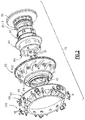
- the MTF module 72 generally includes an outer turbine case 80, a mid-turbine frame (MTF) 82 which defines a plurality of hollow vanes 84, a plurality of tie rods 86, multiple of tie rod nuts 88, an inner case 90, a HPT seal 92, a heat shield 94, a LPT seal 96, multiple of centering pins 98 and a borescope plug assembly 100.
- the MTF module 72 supports the mid-bearing compartment 38-3 through which the inner and outer shafts 40, 50 are rotationally supported.
- the mid-turbine frame 82 itself is not loaded by the bearing compartment 38-3.
- the LPT seal 96 may alternatively be referred to as an intermediate seal in other engine architectures.
- Each of the tie rods 86 are mounted to the inner case 90 and extend through a respective vanes 84 to be fastened to the outer turbine case 80 with the multiple of tie rod nuts 88. That is, each tie rod 86 is typically sheathed by a vane 84 through which the tie rod 86 passes ( Figure 3 ), and the MTF 82 is permitted to float relative to the inner and outer cases 90, 80.
- the other vanes 84 may alternatively or additionally provide other service paths.
- the multiple of centering pins 98 are circumferentially distributed between the vanes 84 to engage bosses 102 on the MTF 82 to locate the MTF 82 with respect to the inner case 90 and the outer turbine case 80. It should be understood that various attachment arrangements may alternatively or additionally be utilized.
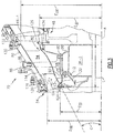
- the MTF 82 is arranged in the core flow path between the high and low pressure turbines 54, 46.
- the vanes 84 interconnect inner and outer platforms 112, 114 that respectively include inner and outer flow path surfaces 113, 115, which define a portion of the core flow path.
- the MTF 82 in one disclosed non-limiting embodiment is cast as a unitary, one-piece component such that the vanes 84 and inner and outer flow path surfaces 113, 115 are provided by a unitary, one-piece cast structure.
- the inner flow path surface 113 and the engine axis A are at an angle G of 20°-35° in the example embodiment.
- the MTF 82 may be cast from a high temperature nickel alloy or other suitable material.
- the inner flow path surface 113 provides inlet and exit inner diameters I ID , E ID relative to the engine axis A.
- the outer flow path surface 115 provides inlet and exit outer diameters I OD , E OD relative to the engine axis A.
- the inner flow path surface 113 extends an axial length L from the inlet inner diameter I ID to the exit inner diameter E ID .
- the ratio (E OD /L) is 3.0-4.5 to 1.
- the ratio (E OD /L) is 3.5-4.0 to 1
- the ratio (E OD /L) is 3.6-3.9 to 1.
- the MTF 82 is sealed to the outer turbine case 80 at an outer forward seal interface 120 and an outer aft seal interface 122.
- the MTF 82 is also sealed to the LPT seal 96, which is attached to the inner case 90 at an inner forward seal interface 124 and an inner aft seal interface 126.
- Each seal interface 120, 122, 124, 126 includes a seal 128, 130, 132, 134 mounted to the inner and outer platforms 112, 114 such as a ring seal, W-seal, C-seal or other seal to seal the MTF 82 relative to the inner and outer cases 90, 80 from a secondary airflow.
Landscapes
- Engineering & Computer Science (AREA)
- Mechanical Engineering (AREA)
- General Engineering & Computer Science (AREA)
- Turbine Rotor Nozzle Sealing (AREA)
Applications Claiming Priority (1)
| Application Number | Priority Date | Filing Date | Title |
|---|---|---|---|
| US14/629,090 US9920641B2 (en) | 2015-02-23 | 2015-02-23 | Gas turbine engine mid-turbine frame configuration |
Publications (1)
| Publication Number | Publication Date |
|---|---|
| EP3059399A1 true EP3059399A1 (fr) | 2016-08-24 |
Family
ID=55453014
Family Applications (1)
| Application Number | Title | Priority Date | Filing Date |
|---|---|---|---|
| EP16156096.6A Withdrawn EP3059399A1 (fr) | 2015-02-23 | 2016-02-17 | Configuration de trame de mi-turbine de moteur à turbine à gaz |
Country Status (2)
| Country | Link |
|---|---|
| US (1) | US9920641B2 (fr) |
| EP (1) | EP3059399A1 (fr) |
Families Citing this family (15)
| Publication number | Priority date | Publication date | Assignee | Title |
|---|---|---|---|---|
| USD793452S1 (en) * | 2014-11-03 | 2017-08-01 | Turbonetics Holdings, Inc. | Compressor inlet for turbocharger |
| US10247035B2 (en) | 2015-07-24 | 2019-04-02 | Pratt & Whitney Canada Corp. | Spoke locking architecture |
| CA2936182C (fr) | 2015-07-24 | 2023-08-15 | Pratt & Whitney Canada Corp. | Systeme et methode de refroidissement multi ailette de chassis mi-turbine |
| US10443449B2 (en) | 2015-07-24 | 2019-10-15 | Pratt & Whitney Canada Corp. | Spoke mounting arrangement |
| US10393381B2 (en) | 2017-01-27 | 2019-08-27 | General Electric Company | Unitary flow path structure |
| US10253643B2 (en) | 2017-02-07 | 2019-04-09 | General Electric Company | Airfoil fluid curtain to mitigate or prevent flow path leakage |
| US10247019B2 (en) | 2017-02-23 | 2019-04-02 | General Electric Company | Methods and features for positioning a flow path inner boundary within a flow path assembly |
| US10385709B2 (en) | 2017-02-23 | 2019-08-20 | General Electric Company | Methods and features for positioning a flow path assembly within a gas turbine engine |
| US10378373B2 (en) | 2017-02-23 | 2019-08-13 | General Electric Company | Flow path assembly with airfoils inserted through flow path boundary |
| US10253641B2 (en) | 2017-02-23 | 2019-04-09 | General Electric Company | Methods and assemblies for attaching airfoils within a flow path |
| US10385731B2 (en) | 2017-06-12 | 2019-08-20 | General Electric Company | CTE matching hanger support for CMC structures |
| US10605119B2 (en) | 2017-09-25 | 2020-03-31 | United Technologies Corporation | Turbine frame assembly for gas turbine engines |
| CN108590786A (zh) * | 2018-04-04 | 2018-09-28 | 中国航发沈阳发动机研究所 | 一种级间机匣承力框架 |
| DE102018222827A1 (de) | 2018-12-21 | 2020-06-25 | MTU Aero Engines AG | Statische Dichtungsanordnung und Strömungsmaschine |
| US11415009B2 (en) * | 2021-01-15 | 2022-08-16 | Raytheon Technologies Corporation | Vane with pin mount and anti-rotation stabilizer rod |
Citations (5)
| Publication number | Priority date | Publication date | Assignee | Title |
|---|---|---|---|---|
| US5160251A (en) * | 1991-05-13 | 1992-11-03 | General Electric Company | Lightweight engine turbine bearing support assembly for withstanding radial and axial loads |
| WO2006038842A1 (fr) * | 2004-10-06 | 2006-04-13 | Volvo Aero Corporation | Structure support a paliers et turbine a gaz comprenant ladite structure |
| EP1921253A2 (fr) * | 2006-10-31 | 2008-05-14 | General Electric Company | Assemblage de moteur de réacteur à double flux et procédé d'assemblage de celui-ci |
| WO2014105577A1 (fr) * | 2012-12-29 | 2014-07-03 | United Technologies Corporation | Canalisation de dalot dans des modules de turbine à gaz |
| WO2014171994A2 (fr) * | 2013-02-01 | 2014-10-23 | United Technologies Corporation | Ensemble fiche d'endoscope pour moteur à turbine à gaz |
Family Cites Families (14)
| Publication number | Priority date | Publication date | Assignee | Title |
|---|---|---|---|---|
| US3902314A (en) * | 1973-11-29 | 1975-09-02 | Avco Corp | Gas turbine engine frame structure |
| US4987736A (en) * | 1988-12-14 | 1991-01-29 | General Electric Company | Lightweight gas turbine engine frame with free-floating heat shield |
| US7870719B2 (en) * | 2006-10-13 | 2011-01-18 | General Electric Company | Plasma enhanced rapidly expanded gas turbine engine transition duct |
| US8347500B2 (en) | 2008-11-28 | 2013-01-08 | Pratt & Whitney Canada Corp. | Method of assembly and disassembly of a gas turbine mid turbine frame |
| US20100132377A1 (en) | 2008-11-28 | 2010-06-03 | Pratt & Whitney Canada Corp. | Fabricated itd-strut and vane ring for gas turbine engine |
| US8061969B2 (en) | 2008-11-28 | 2011-11-22 | Pratt & Whitney Canada Corp. | Mid turbine frame system for gas turbine engine |
| US8500392B2 (en) | 2009-10-01 | 2013-08-06 | Pratt & Whitney Canada Corp. | Sealing for vane segments |
| WO2013047945A1 (fr) | 2011-09-26 | 2013-04-04 | 주식회사 세코닉스 | Film optique ayant un motif atypique, son procédé de fabrication et ensemble de rétroéclairage auquel le film optique est appliqué |
| US8424313B1 (en) * | 2012-01-31 | 2013-04-23 | United Technologies Corporation | Gas turbine engine mid turbine frame with flow turning features |
| JP5221780B1 (ja) | 2012-02-03 | 2013-06-26 | シャープ株式会社 | 映像表示装置およびテレビ受信装置 |
| US10619496B2 (en) | 2013-06-14 | 2020-04-14 | United Technologies Corporation | Turbine vane with variable trailing edge inner radius |
| US11111801B2 (en) | 2013-06-17 | 2021-09-07 | Raytheon Technologies Corporation | Turbine vane with platform pad |
| WO2014210496A1 (fr) | 2013-06-28 | 2014-12-31 | United Technologies Corporation | Élément de détournement d'écoulement pour zone d'étanchéité d'aube d'un moteur à turbine à gaz |
| PL3022400T3 (pl) | 2013-07-15 | 2024-04-22 | Rtx Corporation | Łopatki turbin o zmiennym zaokrągleniu |
-
2015
- 2015-02-23 US US14/629,090 patent/US9920641B2/en active Active
-
2016
- 2016-02-17 EP EP16156096.6A patent/EP3059399A1/fr not_active Withdrawn
Patent Citations (5)
| Publication number | Priority date | Publication date | Assignee | Title |
|---|---|---|---|---|
| US5160251A (en) * | 1991-05-13 | 1992-11-03 | General Electric Company | Lightweight engine turbine bearing support assembly for withstanding radial and axial loads |
| WO2006038842A1 (fr) * | 2004-10-06 | 2006-04-13 | Volvo Aero Corporation | Structure support a paliers et turbine a gaz comprenant ladite structure |
| EP1921253A2 (fr) * | 2006-10-31 | 2008-05-14 | General Electric Company | Assemblage de moteur de réacteur à double flux et procédé d'assemblage de celui-ci |
| WO2014105577A1 (fr) * | 2012-12-29 | 2014-07-03 | United Technologies Corporation | Canalisation de dalot dans des modules de turbine à gaz |
| WO2014171994A2 (fr) * | 2013-02-01 | 2014-10-23 | United Technologies Corporation | Ensemble fiche d'endoscope pour moteur à turbine à gaz |
Also Published As
| Publication number | Publication date |
|---|---|
| US20160245105A1 (en) | 2016-08-25 |
| US9920641B2 (en) | 2018-03-20 |
Similar Documents
| Publication | Publication Date | Title |
|---|---|---|
| US9920641B2 (en) | Gas turbine engine mid-turbine frame configuration | |
| US10352191B2 (en) | Gas turbine engine with air-oil cooler oil tank | |
| EP3808947B1 (fr) | Système de distribution de fluide de turbomachine à engrenage | |
| EP2951404B1 (fr) | Moteur à turbine à gaz et procédé | |
| EP2964935B1 (fr) | Agencement de joint refroidi par fluide pour un moteur à turbine à gaz | |
| US10815891B2 (en) | Inner diffuser case struts for a combustor of a gas turbine engine | |
| US9879558B2 (en) | Low leakage multi-directional interface for a gas turbine engine | |
| US10107118B2 (en) | Flow discourager for vane sealing area of a gas turbine engine | |
| US11649737B2 (en) | Forged cast forged outer case for a gas turbine engine | |
| EP2971677B1 (fr) | Agencement de trois brides pour un moteur à turbine à gaz | |
| US20160047259A1 (en) | Gas turbine engine stress isolation scallop | |
| EP3026222B1 (fr) | Carter pour un moteur à turbine à gaz et procédé de post-usinage associé d'un tel carter | |
| EP3102808B1 (fr) | Tube composite de fluide de refroidissement d'une turbine à gaz | |
| US10502062B2 (en) | Integrally bladed rotor having axial arm and pocket | |
| US10823069B2 (en) | Internal heat exchanger system to cool gas turbine engine components |
Legal Events
| Date | Code | Title | Description |
|---|---|---|---|
| PUAI | Public reference made under article 153(3) epc to a published international application that has entered the european phase |
Free format text: ORIGINAL CODE: 0009012 |
|
| AK | Designated contracting states |
Kind code of ref document: A1 Designated state(s): AL AT BE BG CH CY CZ DE DK EE ES FI FR GB GR HR HU IE IS IT LI LT LU LV MC MK MT NL NO PL PT RO RS SE SI SK SM TR |
|
| AX | Request for extension of the european patent |
Extension state: BA ME |
|
| RAP1 | Party data changed (applicant data changed or rights of an application transferred) |
Owner name: UNITED TECHNOLOGIES CORPORATION |
|
| STAA | Information on the status of an ep patent application or granted ep patent |
Free format text: STATUS: REQUEST FOR EXAMINATION WAS MADE |
|
| 17P | Request for examination filed |
Effective date: 20170222 |
|
| RBV | Designated contracting states (corrected) |
Designated state(s): AL AT BE BG CH CY CZ DE DK EE ES FI FR GB GR HR HU IE IS IT LI LT LU LV MC MK MT NL NO PL PT RO RS SE SI SK SM TR |
|
| STAA | Information on the status of an ep patent application or granted ep patent |
Free format text: STATUS: EXAMINATION IS IN PROGRESS |
|
| 17Q | First examination report despatched |
Effective date: 20180808 |
|
| STAA | Information on the status of an ep patent application or granted ep patent |
Free format text: STATUS: THE APPLICATION IS DEEMED TO BE WITHDRAWN |
|
| 18D | Application deemed to be withdrawn |
Effective date: 20191210 |