EP3059498B1 - Mélangeur principal incliné pour chambre de combustion de stoechiométrie axialement contrôlée - Google Patents
Mélangeur principal incliné pour chambre de combustion de stoechiométrie axialement contrôlée Download PDFInfo
- Publication number
- EP3059498B1 EP3059498B1 EP15201373.6A EP15201373A EP3059498B1 EP 3059498 B1 EP3059498 B1 EP 3059498B1 EP 15201373 A EP15201373 A EP 15201373A EP 3059498 B1 EP3059498 B1 EP 3059498B1
- Authority
- EP
- European Patent Office
- Prior art keywords
- combustor
- fuel delivery
- delivery system
- radial
- fuel
- Prior art date
- Legal status (The legal status is an assumption and is not a legal conclusion. Google has not performed a legal analysis and makes no representation as to the accuracy of the status listed.)
- Active
Links
Images


Classifications
-
- F—MECHANICAL ENGINEERING; LIGHTING; HEATING; WEAPONS; BLASTING
- F23—COMBUSTION APPARATUS; COMBUSTION PROCESSES
- F23R—GENERATING COMBUSTION PRODUCTS OF HIGH PRESSURE OR HIGH VELOCITY, e.g. GAS-TURBINE COMBUSTION CHAMBERS
- F23R3/00—Continuous combustion chambers using liquid or gaseous fuel
- F23R3/28—Continuous combustion chambers using liquid or gaseous fuel characterised by the fuel supply
- F23R3/286—Continuous combustion chambers using liquid or gaseous fuel characterised by the fuel supply having fuel-air premixing devices
-
- F—MECHANICAL ENGINEERING; LIGHTING; HEATING; WEAPONS; BLASTING
- F23—COMBUSTION APPARATUS; COMBUSTION PROCESSES
- F23R—GENERATING COMBUSTION PRODUCTS OF HIGH PRESSURE OR HIGH VELOCITY, e.g. GAS-TURBINE COMBUSTION CHAMBERS
- F23R3/00—Continuous combustion chambers using liquid or gaseous fuel
- F23R3/28—Continuous combustion chambers using liquid or gaseous fuel characterised by the fuel supply
- F23R3/34—Feeding into different combustion zones
- F23R3/346—Feeding into different combustion zones for staged combustion
-
- F—MECHANICAL ENGINEERING; LIGHTING; HEATING; WEAPONS; BLASTING
- F23—COMBUSTION APPARATUS; COMBUSTION PROCESSES
- F23R—GENERATING COMBUSTION PRODUCTS OF HIGH PRESSURE OR HIGH VELOCITY, e.g. GAS-TURBINE COMBUSTION CHAMBERS
- F23R3/00—Continuous combustion chambers using liquid or gaseous fuel
- F23R3/42—Continuous combustion chambers using liquid or gaseous fuel characterised by the arrangement or form of the flame tubes or combustion chambers
- F23R3/50—Combustion chambers comprising an annular flame tube within an annular casing
-
- F—MECHANICAL ENGINEERING; LIGHTING; HEATING; WEAPONS; BLASTING
- F23—COMBUSTION APPARATUS; COMBUSTION PROCESSES
- F23R—GENERATING COMBUSTION PRODUCTS OF HIGH PRESSURE OR HIGH VELOCITY, e.g. GAS-TURBINE COMBUSTION CHAMBERS
- F23R3/00—Continuous combustion chambers using liquid or gaseous fuel
- F23R3/28—Continuous combustion chambers using liquid or gaseous fuel characterised by the fuel supply
- F23R3/283—Attaching or cooling of fuel injecting means including supports for fuel injectors, stems, or lances
Definitions
- the present invention relates to combustion systems for gas turbine engines, and, more specifically, to an angled radial fuel/air mixture delivery system for a combustor.
- Gas turbine engines may comprise a compressor for pressurizing an air supply, a combustor for burning a fuel, and a turbine for converting the energy from combustion into mechanical energy.
- the combustor may have an inner liner and an outer liner that define a combustion chamber.
- a fuel injector would typically introduce fuel into the front section of the combustor.
- NOx nitrogen oxide
- Such emissions are subject to administrative regulation.
- a fuel staged lean burn combustor may be used.
- axially staged combustors may include pilot fuel injectors and radial main mixers. The pilot fuel injectors introduce fuel into the front section of the combustor, while the radial main mixers located downstream of the pilot injectors deliver fuel/air mixture radially at an angle into the combustor.
- the main flame generated by the main radial mixer may have a very long flame length.
- the main flame may either extend to the combustor exit or be quenched by the opposite side liner.
- long flame lengths corresponding to greater combustor lengths may decrease performance.
- quenching the main flame on the opposite side liner may result in a poor burn. Poor mixing will result in poor pattern factor.
- a prior art combustor having the features of the preamble of claim 1 is disclosed in US 2,999,359 .
- Other related combustors of the prior art are known from documents US 4,192,139 , US 2013/0098044 A1 , and EP 0727611 A1 .
- the present invention provides a combustor in accordance with claim 1.
- the axial fuel delivery system may be configured to deliver fuel in a gas flow path.
- the radial fuel delivery system may be configured to direct the mixture of fuel and air into the combustor at an angle between 15 degrees and 75 degrees relative to the normal of gas flow path.
- a liner may have the radial fuel delivery system extending at least partially though the liner.
- the combustor may comprise a plurality of axial fuel delivery systems with one to three radial fuel delivery systems for each axial fuel delivery system.
- the present invention provides a gas turbine engine in accordance with claim 7.
- any reference to singular includes plural embodiments.
- any reference to attached, fixed, connected or the like may include permanent, removable, temporary, partial, full and/or any other possible attachment option.
- Surface shading lines may be used throughout the figures to denote different parts but not necessarily to denote the same or different materials.
- tail refers to the direction associated with the tail (e.g., the back end) of an aircraft, or generally, to the direction of exhaust of the gas turbine.
- forward refers to the direction associated with the nose (e.g., the front end) of an aircraft, or generally, to the direction of flight or motion.
- distal refers to the direction radially outward, or generally, away from the axis of rotation of a turbine engine.
- proximal refers to a direction radially inward, or generally, towards the axis of rotation of a turbine engine.
- Gas turbine engine 20 may be a two-spool turbofan that generally incorporates a fan section 22, a compressor section 24, a combustor section 26 and a turbine section 28.
- Alternative engines may include, for example, an augmentor section among other systems or features.
- fan section 22 can drive coolant (e.g., air) along a bypass flow-path B while compressor section 24 can drive coolant along a core flow-path C for compression and communication into combustor section 26 then expansion through turbine section 28.
- coolant e.g., air
- compressor section 24 can drive coolant along a core flow-path C for compression and communication into combustor section 26 then expansion through turbine section 28.
- Gas turbine engine 20 may generally comprise a low speed spool 30 and a high speed spool 32 mounted for rotation about an engine central longitudinal axis A-A' relative to an engine static structure 36 via several bearing systems 38, 38-1, and 38-2. It should be understood that various bearing systems 38 at various locations may alternatively or additionally be provided, including for example, bearing system 38, bearing system 38-1, and bearing system 38-2.
- Low speed spool 30 may generally comprise an inner shaft 40 that interconnects a fan 42, a low-pressure compressor 44 and a low-pressure turbine 46.
- Inner shaft 40 may be connected to fan 42 through a geared architecture 48 that can drive fan 42 at a lower speed than low speed spool 30.
- Geared architecture 48 may comprise a gear assembly 60 enclosed within a gear housing 62.
- Gear assembly 60 couples inner shaft 40 to a rotating fan structure.
- High speed spool 32 may comprise an outer shaft 50 that interconnects a high-pressure compressor 52 and high-pressure turbine 54.
- a combustor 56 may be located between high-pressure compressor 52 and high-pressure turbine 54.
- Mid-turbine frame 57 may support one or more bearing systems 38 in turbine section 28.
- Inner shaft 40 and outer shaft 50 may be concentric and rotate via bearing systems 38 about the engine central longitudinal axis A-A', which is collinear with their longitudinal axes.
- A-A' the engine central longitudinal axis A-A'
- a "high-pressure” compressor or turbine experiences a higher pressure than a corresponding "low-pressure” compressor or turbine.
- the core airflow C may be compressed by low-pressure compressor 44 then high-pressure compressor 52, mixed and burned with fuel in combustor 56, then expanded over high-pressure turbine 54 and low-pressure turbine 46.
- Mid-turbine frame 57 includes airfoils 59, which are in the core airflow path. Airfoils 59 may be formed integrally into a full-ring, mid-turbine-frame stator and retained by a retention pin. Turbines 46, 54 rotationally drive the respective low speed spool 30 and high speed spool 32 in response to the expansion.
- Gas turbine engine 20 may be, for example, a high-bypass ratio geared aircraft engine.
- the bypass ratio of gas turbine engine 20 may be greater than about six (6:1).
- the bypass ratio of gas turbine engine 20 may be greater than ten (10:1).
- geared architecture 48 may be an epicyclic gear train, such as a star gear system (sun gear in meshing engagement with a plurality of star gears supported by a carrier and in meshing engagement with a ring gear) or other gear system.
- Geared architecture 48 may have a gear reduction ratio of greater than about 2.3 (2:3:1) and low-pressure turbine 46 may have a pressure ratio that is greater than about five (5:1).
- the bypass ratio of gas turbine engine 20 is greater than about ten (10:1).
- the diameter of fan 42 may be significantly larger than that of the low-pressure compressor 44.
- Low-pressure turbine 46 pressure ratio may be measured prior to inlet of low-pressure turbine 46 as related to the pressure at the outlet of low-pressure turbine 46 prior to an exhaust nozzle. It should be understood, however, that the above parameters are exemplary of various embodiments of a suitable geared architecture engine and that the present disclosure contemplates other turbine engines including direct drive turbofans.
- Combustor 56 includes both radial and axial fuel delivery systems, as discussed in further detail below.
- the radial fuel delivery systems are angled relative to the axial gas flow through combustor 56. Angling the radial duel delivery systems of combustor 56 may impact the completeness of the fuel burn and thus emissions. Angling the radial fuel delivery system may also impact the length of ignited gasses ejected from the radial fuel delivery system.
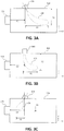
- a combustor 56 having an axial fuel delivery system 106 at a forward location of the combustor and a radial fuel delivery system 112 aft of axial fuel delivery system 106 is described.
- a xy axis is provided for ease of description.
- Radial fuel delivery system 112 delivers fuel into combustion chamber 104 in an at least partially radial direction (i.e., the y direction).
- Radial fuel delivery system 112 has nozzle 113 in cavity 116 defined by bluff body 118 and mixer 110.
- Mixer 110 mixes the fuel delivered by radial fuel delivery system 112 with air and provides a stable burn pattern.
- Mixer 110 comprises a bluff body 118 extending from inner walls of mixer 110, as described in further detail below. Mixer 110 may rest in opening 108 defined by combustor liner 102. Mixer 110 may be secured to combustor 56 by tabs 114.
- radial fuel delivery system 112 may deliver fuel into combustor 56 in direction 120.
- Fuel delivery direction 120 is the direction that fuel is traveling when leaving nozzle 113 and/or mixer 110.
- Fuel delivery direction 120 may have a radial component (i.e., in the y direction) and an axial component (i.e., in the x direction).
- Gas flow direction 122 is the direction of compressed gas in core flowpath C (of FIG. 1 ) entering combustor 56. Fuel delivered by axial fuel delivery system 106 moves in gas flow direction 122.
- fuel delivery direction 120 is selected relative to a gas flow direction 122.
- the angle between the gas flow direction 122 and fuel delivery direction 120 may be described as negative, neutral, or positive.
- Radial fuel delivery system 112 is at a "negative angle" when gas flow direction 122 and fuel delivery direction 120 are oriented with angle ⁇ being acute (i.e., less than 90°) and angle ⁇ being obtuse (i.e., greater than 90°).
- radial fuel delivery system 112 at a negative angle directs a fuel/air mixture at least partially upstream or in a direction opposite gas flow direction 122.
- Radial fuel delivery system 112 is at a "positive angle" when gas flow direction 122 and fuel delivery direction 120 are oriented with angle ⁇ being obtuse (i.e., greater than 90°) and angle ⁇ being acute (i.e., less than 90°). Radial fuel delivery system 112 is at a "neutral angle" when both angles ⁇ and ⁇ are approximately 90°.
- a radial fuel delivery system 112 oriented so that fuel delivery direction 120 is oriented relative to gas flow direction 122 with angle ⁇ being between 5° and 85° or in various embodiments between 15° and 75°.
- angle ⁇ being between 5° and 85° or in various embodiments between 15° and 75°.
- a combustor 150 is shown with axial fuel delivery system 152 oriented at a positive angle, not according to the invention.
- Radial fuel delivery system 154 may be aft of axial fuel delivery system 152 and separated from axial fuel delivery system 152 by a distance D 1 .
- Gas in combustor 150 may flow generally in an aft direction (i.e., a direction along the x axis).
- Radial fuel delivery system may deliver fuel into combustor 150 at an angle relative to gas flow direction defined by the x axis.
- Radial fuel delivery system 154 may also deliver fuel at an angle relative to a radial direction (i.e., a direction along the y axis).
- Axial fuel delivery system 152 oriented at a positive angle may produce flame 156 with large X 1 (width) and Y 1 (height) dimensions relative to an axial fuel delivery system oriented at a negative angle, as described in further detail below.
- a combustor 160 is shown with axial fuel delivery system 162 oriented at a neutral angle (i.e., a right angle), not according to the invention.
- Radial fuel delivery system 164 may be aft of axial fuel delivery system 162 and separated from axial fuel delivery system 162 by a distance D 2 .
- Gas in combustor 160 may flow generally in an aft direction (i.e., a direction along the x axis).
- Radial fuel delivery system may deliver fuel into combustor 160 perpendicular to gas flow direction defined by the x axis.
- Radial fuel delivery system 164 may also deliver fuel perpendicular to a radial direction (i.e., a direction along the y axis).
- Axial fuel delivery system 162 oriented at a positive angle may produce flame 166 with large X 2 (width) and Y 2 (height) dimensions relative to an axial fuel delivery system oriented at a negative angle, as described in further detail below.
- a combustor 170 is shown with axial fuel delivery system 172 oriented at a negative angle, in accordance with various embodiments of the invention.
- Radial fuel delivery system 174 is aft of axial fuel delivery system 172 and separated from axial fuel delivery system 172 by a distance D 1 .
- Gas in combustor 170 flows generally in an aft direction (i.e., a direction along the x axis).
- Radial fuel delivery system 172 delivers fuel into combustor 170 at an angle relative to the direction of the gas flow in combustor 170 defined by the x axis as depicted.
- radial fuel delivery system 172 delivers a fuel mixture in at least a partially upstream direction relative to the flow of gas in combustor 170 (i.e., moving at least partially forward towards axial fuel delivery system 172 as depicted).
- Radial fuel delivery system 174 may also deliver fuel at an angle relative to a radial direction (i.e., a direction along the y axis).
- Axial fuel delivery system 172 oriented at a negative angle may produce flame 176 with small X 3 (width) and Y 3 (height) dimensions relative to an axial fuel delivery system oriented at a positive or neutral angle, as described above.
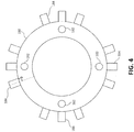
- annular combustor 180 is shown as viewed from forward to aft with axial fuel delivery systems 182 and radial fuel delivery systems 184.
- Annular combustor 180 may have multiple radial fuel delivery systems 184 for each axial fuel delivery system 182.
- Axial fuel delivery systems 182 may serve as pilot lights. The combustion supported by axial fuel delivery system 182 ignites fuel mixture exiting radial fuel delivery system 184.
- annular combustor 180 may include one or more radial fuel delivery systems 184 for each axial fuel delivery system 182 (e.g., one to three radial fuel delivery systems 184 for each axial fuel delivery system 182).
- Each radial fuel delivery system 184 may be oriented at radial angle ⁇ relative to a radial direction. Radial fuel delivery system 184 may be oriented at a negative axial angle ⁇ (as shown in FIG. 2 ) with a radial angle ⁇ (in a circumferential direction) between -90° and 90°. Radial fuel delivery system 184 oriented at a negative axial angle ⁇ may tend to provide improved fuel burn and a short flame length for any radial angle ⁇ .
Landscapes
- Engineering & Computer Science (AREA)
- Chemical & Material Sciences (AREA)
- Combustion & Propulsion (AREA)
- Mechanical Engineering (AREA)
- General Engineering & Computer Science (AREA)
- Pre-Mixing And Non-Premixing Gas Burner (AREA)
Claims (7)
- Chambre de combustion (56), comprenant :un système d'alimentation en carburant axial (106 ; 152 ; 162 ; 172 ; 182) ; etun système d'alimentation en carburant radial (112 ; 154 ; 164 ; 174 ; 184) à l'arrière ou en aval du système d'alimentation en carburant axial (106 ; 152 ; 162 ; 172 ; 182), dans laquelle le système d'alimentation en carburant radial (112 ; 154 ; 164 ; 174 ; 184) est configuré pour diriger le carburant au moins partiellement dans une direction amont par rapport à une direction d'écoulement de gaz (122), dans laquelle la direction d'écoulement de gaz (122) est la direction du gaz comprimé dans un trajet d'écoulement principal (C) entrant dans la chambre de combustion (56) ; caractérisée en ce quele système d'alimentation en carburant radial (112 ; 154 ; 164 ; 174 ; 184) est configuré pour diriger un mélange de carburant et d'air dans la chambre de combustion (56) à un angle axial (α) compris entre 5 degrés et 85 degrés par rapport à la direction d'écoulement de gaz (122) ;dans laquelle le système d'alimentation en carburant radial (112 ; 154 ; 164 ; 174 ; 184) comprend :un mélangeur (110) comportant un corps non profilé (118) s'étendant à partir de parois internes du mélangeur (110) ; etune buse (113) dans une cavité (116) définie par le corps non profilé (118) et le mélangeur (110), dans laquelle le carburant du mélange de carburant et d'air quitte la buse (113) se déplaçant à l'angle axial (α) compris entre 5 degrés et 85 degrés par rapport à la direction d'écoulement de gaz (122), et le système d'alimentation en carburant axial (106 ; 152 ; 162 ; 172 ; 182) allume le mélange de carburant et d'air sortant du système d'alimentation en carburant radial (112 ; 154 ; 164 ; 174 ; 184).
- Chambre de combustion selon la revendication 1, dans laquelle le système d'alimentation en carburant axial (106 ; 152 ; 162 ; 172 ; 182) est configuré pour fournir du carburant dans la direction d'écoulement de gaz (122).
- Chambre de combustion selon la revendication 1 ou 2, dans laquelle le système d'alimentation en carburant radial (112 ; 154 ; 164 ; 174 ; 184) est configuré pour diriger le mélange de carburant et d'air dans la chambre de combustion (56) à un angle axial (α) compris entre 15 degrés et 75 degrés par rapport à la direction d'écoulement de gaz (122).
- Chambre de combustion selon une quelconque revendication précédente, comprenant en outre une chemise (102) avec le système d'alimentation en carburant radial (112 ; 154 ; 164 ; 174 ; 184) s'étendant au moins partiellement à travers la chemise (102).
- Chambre de combustion selon une quelconque revendication précédente, dans laquelle le mélangeur (110) repose dans une ouverture (108) définie par une/la chemise de chambre de combustion (102).
- Chambre de combustion selon une quelconque revendication précédente, dans laquelle la chambre de combustion (56) comprend en outre une pluralité de systèmes d'alimentation en carburant axiaux (106 ; 152 ; 162 ; 172 ; 182) ayant entre un et trois, ou au moins un à trois, systèmes d'alimentation en carburant radiaux (112 ; 154 ; 164 ; 174 ; 184) pour chaque système d'alimentation en carburant axial (106 ; 152 ; 162 ; 172 ; 182).
- Moteur à turbine à gaz (20), comprenant :un compresseur (24) ; etla chambre de combustion selon une quelconque revendication précédente à l'arrière du compresseur (24).
Applications Claiming Priority (1)
| Application Number | Priority Date | Filing Date | Title |
|---|---|---|---|
| US14/627,709 US10060629B2 (en) | 2015-02-20 | 2015-02-20 | Angled radial fuel/air delivery system for combustor |
Publications (2)
| Publication Number | Publication Date |
|---|---|
| EP3059498A1 EP3059498A1 (fr) | 2016-08-24 |
| EP3059498B1 true EP3059498B1 (fr) | 2020-10-21 |
Family
ID=54850482
Family Applications (1)
| Application Number | Title | Priority Date | Filing Date |
|---|---|---|---|
| EP15201373.6A Active EP3059498B1 (fr) | 2015-02-20 | 2015-12-18 | Mélangeur principal incliné pour chambre de combustion de stoechiométrie axialement contrôlée |
Country Status (2)
| Country | Link |
|---|---|
| US (1) | US10060629B2 (fr) |
| EP (1) | EP3059498B1 (fr) |
Families Citing this family (14)
| Publication number | Priority date | Publication date | Assignee | Title |
|---|---|---|---|---|
| CN103917826B (zh) * | 2011-11-17 | 2016-08-24 | 通用电气公司 | 涡轮机燃烧器组件和操作涡轮机的方法 |
| US20150159877A1 (en) * | 2013-12-06 | 2015-06-11 | General Electric Company | Late lean injection manifold mixing system |
| US10139111B2 (en) * | 2014-03-28 | 2018-11-27 | Siemens Energy, Inc. | Dual outlet nozzle for a secondary fuel stage of a combustor of a gas turbine engine |
| US10954859B2 (en) | 2017-07-25 | 2021-03-23 | Raytheon Technologies Corporation | Low emissions combustor assembly for gas turbine engine |
| US11156164B2 (en) | 2019-05-21 | 2021-10-26 | General Electric Company | System and method for high frequency accoustic dampers with caps |
| US11174792B2 (en) | 2019-05-21 | 2021-11-16 | General Electric Company | System and method for high frequency acoustic dampers with baffles |
| CN111396927B (zh) * | 2020-03-27 | 2021-06-08 | 中国科学院工程热物理研究所 | 二维阵列无传统旋流器的低污染燃烧装置 |
| US11619172B1 (en) | 2022-03-01 | 2023-04-04 | General Electric Company | Detonation combustion systems |
| US12196422B2 (en) * | 2022-05-25 | 2025-01-14 | General Electric Company | Combustor with secondary fuel nozzle in dilution fence |
| US20240401811A1 (en) * | 2023-05-31 | 2024-12-05 | General Electric Company | Turbine engine including a combustor |
| US12130016B1 (en) | 2023-05-31 | 2024-10-29 | General Electric Company | Turbine engine including a combustor |
| US12429220B2 (en) * | 2023-06-14 | 2025-09-30 | General Electric Company | Combustion section with a primary combustor and a set of secondary combustors |
| US12173898B1 (en) * | 2023-09-01 | 2024-12-24 | General Electric Company | Combustion section with a primary combustor and a set of secondary combustors |
| EP4517173A1 (fr) | 2023-09-01 | 2025-03-05 | General Electric Company | Section de combustion avec une chambre de combustion primaire et un ensemble de chambres de combustion secondaires |
Citations (3)
| Publication number | Priority date | Publication date | Assignee | Title |
|---|---|---|---|---|
| US4192139A (en) * | 1976-07-02 | 1980-03-11 | Volkswagenwerk Aktiengesellschaft | Combustion chamber for gas turbines |
| EP0727611A1 (fr) * | 1995-02-20 | 1996-08-21 | ABB Management AG | Chambre de combustion avec combustion en deux étages |
| US20130098044A1 (en) * | 2011-10-19 | 2013-04-25 | General Electric Company | Flashback resistant tubes in tube lli design |
Family Cites Families (51)
| Publication number | Priority date | Publication date | Assignee | Title |
|---|---|---|---|---|
| US1793640A (en) * | 1926-04-26 | 1931-02-24 | Holzwarth Gas Turbine Co | Combustion engine |
| US2999359A (en) * | 1956-04-25 | 1961-09-12 | Rolls Royce | Combustion equipment of gas-turbine engines |
| GB834975A (en) | 1957-07-23 | 1960-05-18 | Robert Archibald Brown Lang | Afterburner installation |
| US3872664A (en) * | 1973-10-15 | 1975-03-25 | United Aircraft Corp | Swirl combustor with vortex burning and mixing |
| US4045956A (en) * | 1974-12-18 | 1977-09-06 | United Technologies Corporation | Low emission combustion chamber |
| US3977186A (en) * | 1975-07-24 | 1976-08-31 | General Motors Corporation | Impinging air jet combustion apparatus |
| US4265615A (en) * | 1978-12-11 | 1981-05-05 | United Technologies Corporation | Fuel injection system for low emission burners |
| US4420929A (en) * | 1979-01-12 | 1983-12-20 | General Electric Company | Dual stage-dual mode low emission gas turbine combustion system |
| US5205117A (en) * | 1989-12-21 | 1993-04-27 | Sundstrand Corporation | High altitude starting two-stage fuel injection |
| US5259184A (en) * | 1992-03-30 | 1993-11-09 | General Electric Company | Dry low NOx single stage dual mode combustor construction for a gas turbine |
| US5487275A (en) * | 1992-12-11 | 1996-01-30 | General Electric Co. | Tertiary fuel injection system for use in a dry low NOx combustion system |
| CA2124069A1 (fr) * | 1993-05-24 | 1994-11-25 | Boris M. Kramnik | Chambre de combustion de turbine a gaz a geometrie invariable, a faible niveau de pollution |
| US5454221A (en) * | 1994-03-14 | 1995-10-03 | General Electric Company | Dilution flow sleeve for reducing emissions in a gas turbine combustor |
| JPH08270950A (ja) * | 1995-02-01 | 1996-10-18 | Mitsubishi Heavy Ind Ltd | ガスタービン燃焼器 |
| US5647215A (en) * | 1995-11-07 | 1997-07-15 | Westinghouse Electric Corporation | Gas turbine combustor with turbulence enhanced mixing fuel injectors |
| US5924276A (en) * | 1996-07-17 | 1999-07-20 | Mowill; R. Jan | Premixer with dilution air bypass valve assembly |
| US6530223B1 (en) * | 1998-10-09 | 2003-03-11 | General Electric Company | Multi-stage radial axial gas turbine engine combustor |
| US6286298B1 (en) * | 1998-12-18 | 2001-09-11 | General Electric Company | Apparatus and method for rich-quench-lean (RQL) concept in a gas turbine engine combustor having trapped vortex cavity |
| US6311471B1 (en) * | 1999-01-08 | 2001-11-06 | General Electric Company | Steam cooled fuel injector for gas turbine |
| US6925809B2 (en) * | 1999-02-26 | 2005-08-09 | R. Jan Mowill | Gas turbine engine fuel/air premixers with variable geometry exit and method for controlling exit velocities |
| US6298667B1 (en) * | 2000-06-22 | 2001-10-09 | General Electric Company | Modular combustor dome |
| US6536216B2 (en) * | 2000-12-08 | 2003-03-25 | General Electric Company | Apparatus for injecting fuel into gas turbine engines |
| US7003961B2 (en) * | 2001-07-23 | 2006-02-28 | Ramgen Power Systems, Inc. | Trapped vortex combustor |
| US6868676B1 (en) * | 2002-12-20 | 2005-03-22 | General Electric Company | Turbine containing system and an injector therefor |
| US7093441B2 (en) * | 2003-10-09 | 2006-08-22 | United Technologies Corporation | Gas turbine annular combustor having a first converging volume and a second converging volume, converging less gradually than the first converging volume |
| US7954325B2 (en) * | 2005-12-06 | 2011-06-07 | United Technologies Corporation | Gas turbine combustor |
| US8387390B2 (en) * | 2006-01-03 | 2013-03-05 | General Electric Company | Gas turbine combustor having counterflow injection mechanism |
| EP1847778A1 (fr) * | 2006-04-21 | 2007-10-24 | Siemens Aktiengesellschaft | Système de combustion à prémélange d'une turbine à gaz et son procédé de fonctionnement |
| US7886545B2 (en) * | 2007-04-27 | 2011-02-15 | General Electric Company | Methods and systems to facilitate reducing NOx emissions in combustion systems |
| US8387398B2 (en) * | 2007-09-14 | 2013-03-05 | Siemens Energy, Inc. | Apparatus and method for controlling the secondary injection of fuel |
| US7665309B2 (en) * | 2007-09-14 | 2010-02-23 | Siemens Energy, Inc. | Secondary fuel delivery system |
| US8112216B2 (en) * | 2009-01-07 | 2012-02-07 | General Electric Company | Late lean injection with adjustable air splits |
| US8707707B2 (en) * | 2009-01-07 | 2014-04-29 | General Electric Company | Late lean injection fuel staging configurations |
| US8701418B2 (en) * | 2009-01-07 | 2014-04-22 | General Electric Company | Late lean injection for fuel flexibility |
| JP4797079B2 (ja) * | 2009-03-13 | 2011-10-19 | 川崎重工業株式会社 | ガスタービン燃焼器 |
| US8991192B2 (en) * | 2009-09-24 | 2015-03-31 | Siemens Energy, Inc. | Fuel nozzle assembly for use as structural support for a duct structure in a combustor of a gas turbine engine |
| US20110289929A1 (en) * | 2010-05-28 | 2011-12-01 | General Electric Company | Turbomachine fuel nozzle |
| US8479521B2 (en) * | 2011-01-24 | 2013-07-09 | United Technologies Corporation | Gas turbine combustor with liner air admission holes associated with interspersed main and pilot swirler assemblies |
| US9068748B2 (en) * | 2011-01-24 | 2015-06-30 | United Technologies Corporation | Axial stage combustor for gas turbine engines |
| EP2742291B1 (fr) * | 2011-08-11 | 2020-07-08 | General Electric Company | Système pour injecter du carburant dans un moteur à turbine à gaz |
| DE112011105655B4 (de) * | 2011-09-22 | 2023-05-25 | General Electric Company | Brenner und Verfahren zur Brennstoffzufuhr zu einem Brenner |
| CN103917826B (zh) * | 2011-11-17 | 2016-08-24 | 通用电气公司 | 涡轮机燃烧器组件和操作涡轮机的方法 |
| US20130318991A1 (en) * | 2012-05-31 | 2013-12-05 | General Electric Company | Combustor With Multiple Combustion Zones With Injector Placement for Component Durability |
| JP5949363B2 (ja) * | 2012-09-13 | 2016-07-06 | 株式会社Ihi | 可変ノズルユニット及び可変容量型過給機 |
| US20140301820A1 (en) * | 2013-04-03 | 2014-10-09 | Uwe Lohse | Turbine engine shutdown temperature control system with nozzle injection for a gas turbine engine |
| EP3008391B1 (fr) | 2013-06-11 | 2020-05-06 | United Technologies Corporation | Chambre de combustion à étagement axial pour un moteur à turbine à gaz |
| EP3060850B1 (fr) * | 2013-10-24 | 2020-05-13 | United Technologies Corporation | Chambre de combustion annulaire étagée circonférentiellement et axialement pour chambre de combustion de moteur à turbine à gaz |
| US9551490B2 (en) * | 2014-04-08 | 2017-01-24 | General Electric Company | System for cooling a fuel injector extending into a combustion gas flow field and method for manufacture |
| EP2955445B1 (fr) * | 2014-06-12 | 2019-11-27 | Kawasaki Jukogyo Kabushiki Kaisha | Chambre de combustion de turbine a gaz operant avec differents types de carburants |
| US20160047317A1 (en) * | 2014-08-14 | 2016-02-18 | General Electric Company | Fuel injector assemblies in combustion turbine engines |
| US9797601B2 (en) * | 2015-01-21 | 2017-10-24 | United Technologies Corporation | Bluff body fuel mixer |
-
2015
- 2015-02-20 US US14/627,709 patent/US10060629B2/en active Active
- 2015-12-18 EP EP15201373.6A patent/EP3059498B1/fr active Active
Patent Citations (3)
| Publication number | Priority date | Publication date | Assignee | Title |
|---|---|---|---|---|
| US4192139A (en) * | 1976-07-02 | 1980-03-11 | Volkswagenwerk Aktiengesellschaft | Combustion chamber for gas turbines |
| EP0727611A1 (fr) * | 1995-02-20 | 1996-08-21 | ABB Management AG | Chambre de combustion avec combustion en deux étages |
| US20130098044A1 (en) * | 2011-10-19 | 2013-04-25 | General Electric Company | Flashback resistant tubes in tube lli design |
Also Published As
| Publication number | Publication date |
|---|---|
| US10060629B2 (en) | 2018-08-28 |
| EP3059498A1 (fr) | 2016-08-24 |
| US20160245523A1 (en) | 2016-08-25 |
Similar Documents
| Publication | Publication Date | Title |
|---|---|---|
| EP3059498B1 (fr) | Mélangeur principal incliné pour chambre de combustion de stoechiométrie axialement contrôlée | |
| US11719158B2 (en) | Low emissions combustor assembly for gas turbine engine | |
| US10816209B2 (en) | Bluff body fuel mixer | |
| EP3301361B1 (fr) | Décalage de carburant pilote/principal dans une chambre de combustion à étage axial pour un moteur à turbine à gaz | |
| US10465909B2 (en) | Mini mixing fuel nozzle assembly with mixing sleeve | |
| EP3008391B1 (fr) | Chambre de combustion à étagement axial pour un moteur à turbine à gaz | |
| US11365884B2 (en) | Radial fuel shifting and biasing in an axial staged combustor for a gas turbine engine | |
| US11788725B2 (en) | Trapped vortex combustor for a gas turbine engine with a driver airflow channel | |
| EP3301372B1 (fr) | Polarisation et décalage de carburant circonférentiels dans une chambre de combustion étagée axiale pour un moteur à turbine à gaz | |
| US10907833B2 (en) | Axial staged combustor with restricted main fuel injector | |
| US20160312631A1 (en) | Multiple Injector Holes for Gas Turbine Engine Vane | |
| US12152779B1 (en) | Combustor | |
| WO2013138050A1 (fr) | Dispositif de prémélange de carburant et d'air pour turbine à gaz | |
| US12130016B1 (en) | Turbine engine including a combustor | |
| US20240401808A1 (en) | Turbine Engine Including a Combustor | |
| Kim et al. | Angled Radial Fuel/Air Delivery System for Combustor | |
| Cheung et al. | Bluff Body Fuel Mixer |
Legal Events
| Date | Code | Title | Description |
|---|---|---|---|
| PUAI | Public reference made under article 153(3) epc to a published international application that has entered the european phase |
Free format text: ORIGINAL CODE: 0009012 |
|
| AK | Designated contracting states |
Kind code of ref document: A1 Designated state(s): AL AT BE BG CH CY CZ DE DK EE ES FI FR GB GR HR HU IE IS IT LI LT LU LV MC MK MT NL NO PL PT RO RS SE SI SK SM TR |
|
| AX | Request for extension of the european patent |
Extension state: BA ME |
|
| RAP1 | Party data changed (applicant data changed or rights of an application transferred) |
Owner name: UNITED TECHNOLOGIES CORPORATION |
|
| STAA | Information on the status of an ep patent application or granted ep patent |
Free format text: STATUS: REQUEST FOR EXAMINATION WAS MADE |
|
| 17P | Request for examination filed |
Effective date: 20170223 |
|
| RBV | Designated contracting states (corrected) |
Designated state(s): AL AT BE BG CH CY CZ DE DK EE ES FI FR GB GR HR HU IE IS IT LI LT LU LV MC MK MT NL NO PL PT RO RS SE SI SK SM TR |
|
| STAA | Information on the status of an ep patent application or granted ep patent |
Free format text: STATUS: EXAMINATION IS IN PROGRESS |
|
| 17Q | First examination report despatched |
Effective date: 20190508 |
|
| GRAJ | Information related to disapproval of communication of intention to grant by the applicant or resumption of examination proceedings by the epo deleted |
Free format text: ORIGINAL CODE: EPIDOSDIGR1 |
|
| STAA | Information on the status of an ep patent application or granted ep patent |
Free format text: STATUS: GRANT OF PATENT IS INTENDED |
|
| GRAP | Despatch of communication of intention to grant a patent |
Free format text: ORIGINAL CODE: EPIDOSNIGR1 |
|
| INTG | Intention to grant announced |
Effective date: 20200507 |
|
| GRAS | Grant fee paid |
Free format text: ORIGINAL CODE: EPIDOSNIGR3 |
|
| GRAA | (expected) grant |
Free format text: ORIGINAL CODE: 0009210 |
|
| STAA | Information on the status of an ep patent application or granted ep patent |
Free format text: STATUS: THE PATENT HAS BEEN GRANTED |
|
| AK | Designated contracting states |
Kind code of ref document: B1 Designated state(s): AL AT BE BG CH CY CZ DE DK EE ES FI FR GB GR HR HU IE IS IT LI LT LU LV MC MK MT NL NO PL PT RO RS SE SI SK SM TR |
|
| REG | Reference to a national code |
Ref country code: GB Ref legal event code: FG4D |
|
| REG | Reference to a national code |
Ref country code: CH Ref legal event code: EP |
|
| REG | Reference to a national code |
Ref country code: IE Ref legal event code: FG4D |
|
| REG | Reference to a national code |
Ref country code: DE Ref legal event code: R096 Ref document number: 602015060726 Country of ref document: DE |
|
| REG | Reference to a national code |
Ref country code: AT Ref legal event code: REF Ref document number: 1326207 Country of ref document: AT Kind code of ref document: T Effective date: 20201115 |
|
| REG | Reference to a national code |
Ref country code: AT Ref legal event code: MK05 Ref document number: 1326207 Country of ref document: AT Kind code of ref document: T Effective date: 20201021 |
|
| RAP2 | Party data changed (patent owner data changed or rights of a patent transferred) |
Owner name: RAYTHEON TECHNOLOGIES CORPORATION |
|
| REG | Reference to a national code |
Ref country code: NL Ref legal event code: MP Effective date: 20201021 |
|
| PG25 | Lapsed in a contracting state [announced via postgrant information from national office to epo] |
Ref country code: GR Free format text: LAPSE BECAUSE OF FAILURE TO SUBMIT A TRANSLATION OF THE DESCRIPTION OR TO PAY THE FEE WITHIN THE PRESCRIBED TIME-LIMIT Effective date: 20210122 Ref country code: RS Free format text: LAPSE BECAUSE OF FAILURE TO SUBMIT A TRANSLATION OF THE DESCRIPTION OR TO PAY THE FEE WITHIN THE PRESCRIBED TIME-LIMIT Effective date: 20201021 Ref country code: FI Free format text: LAPSE BECAUSE OF FAILURE TO SUBMIT A TRANSLATION OF THE DESCRIPTION OR TO PAY THE FEE WITHIN THE PRESCRIBED TIME-LIMIT Effective date: 20201021 Ref country code: PT Free format text: LAPSE BECAUSE OF FAILURE TO SUBMIT A TRANSLATION OF THE DESCRIPTION OR TO PAY THE FEE WITHIN THE PRESCRIBED TIME-LIMIT Effective date: 20210222 Ref country code: NO Free format text: LAPSE BECAUSE OF FAILURE TO SUBMIT A TRANSLATION OF THE DESCRIPTION OR TO PAY THE FEE WITHIN THE PRESCRIBED TIME-LIMIT Effective date: 20210121 Ref country code: NL Free format text: LAPSE BECAUSE OF FAILURE TO SUBMIT A TRANSLATION OF THE DESCRIPTION OR TO PAY THE FEE WITHIN THE PRESCRIBED TIME-LIMIT Effective date: 20201021 |
|
| REG | Reference to a national code |
Ref country code: LT Ref legal event code: MG4D |
|
| PG25 | Lapsed in a contracting state [announced via postgrant information from national office to epo] |
Ref country code: IS Free format text: LAPSE BECAUSE OF FAILURE TO SUBMIT A TRANSLATION OF THE DESCRIPTION OR TO PAY THE FEE WITHIN THE PRESCRIBED TIME-LIMIT Effective date: 20210221 Ref country code: SE Free format text: LAPSE BECAUSE OF FAILURE TO SUBMIT A TRANSLATION OF THE DESCRIPTION OR TO PAY THE FEE WITHIN THE PRESCRIBED TIME-LIMIT Effective date: 20201021 Ref country code: LV Free format text: LAPSE BECAUSE OF FAILURE TO SUBMIT A TRANSLATION OF THE DESCRIPTION OR TO PAY THE FEE WITHIN THE PRESCRIBED TIME-LIMIT Effective date: 20201021 Ref country code: PL Free format text: LAPSE BECAUSE OF FAILURE TO SUBMIT A TRANSLATION OF THE DESCRIPTION OR TO PAY THE FEE WITHIN THE PRESCRIBED TIME-LIMIT Effective date: 20201021 Ref country code: BG Free format text: LAPSE BECAUSE OF FAILURE TO SUBMIT A TRANSLATION OF THE DESCRIPTION OR TO PAY THE FEE WITHIN THE PRESCRIBED TIME-LIMIT Effective date: 20210121 Ref country code: AT Free format text: LAPSE BECAUSE OF FAILURE TO SUBMIT A TRANSLATION OF THE DESCRIPTION OR TO PAY THE FEE WITHIN THE PRESCRIBED TIME-LIMIT Effective date: 20201021 Ref country code: ES Free format text: LAPSE BECAUSE OF FAILURE TO SUBMIT A TRANSLATION OF THE DESCRIPTION OR TO PAY THE FEE WITHIN THE PRESCRIBED TIME-LIMIT Effective date: 20201021 |
|
| PG25 | Lapsed in a contracting state [announced via postgrant information from national office to epo] |
Ref country code: HR Free format text: LAPSE BECAUSE OF FAILURE TO SUBMIT A TRANSLATION OF THE DESCRIPTION OR TO PAY THE FEE WITHIN THE PRESCRIBED TIME-LIMIT Effective date: 20201021 |
|
| REG | Reference to a national code |
Ref country code: DE Ref legal event code: R097 Ref document number: 602015060726 Country of ref document: DE |
|
| PG25 | Lapsed in a contracting state [announced via postgrant information from national office to epo] |
Ref country code: SK Free format text: LAPSE BECAUSE OF FAILURE TO SUBMIT A TRANSLATION OF THE DESCRIPTION OR TO PAY THE FEE WITHIN THE PRESCRIBED TIME-LIMIT Effective date: 20201021 Ref country code: RO Free format text: LAPSE BECAUSE OF FAILURE TO SUBMIT A TRANSLATION OF THE DESCRIPTION OR TO PAY THE FEE WITHIN THE PRESCRIBED TIME-LIMIT Effective date: 20201021 Ref country code: LT Free format text: LAPSE BECAUSE OF FAILURE TO SUBMIT A TRANSLATION OF THE DESCRIPTION OR TO PAY THE FEE WITHIN THE PRESCRIBED TIME-LIMIT Effective date: 20201021 Ref country code: SM Free format text: LAPSE BECAUSE OF FAILURE TO SUBMIT A TRANSLATION OF THE DESCRIPTION OR TO PAY THE FEE WITHIN THE PRESCRIBED TIME-LIMIT Effective date: 20201021 Ref country code: EE Free format text: LAPSE BECAUSE OF FAILURE TO SUBMIT A TRANSLATION OF THE DESCRIPTION OR TO PAY THE FEE WITHIN THE PRESCRIBED TIME-LIMIT Effective date: 20201021 Ref country code: CZ Free format text: LAPSE BECAUSE OF FAILURE TO SUBMIT A TRANSLATION OF THE DESCRIPTION OR TO PAY THE FEE WITHIN THE PRESCRIBED TIME-LIMIT Effective date: 20201021 |
|
| REG | Reference to a national code |
Ref country code: CH Ref legal event code: PL |
|
| PLBE | No opposition filed within time limit |
Free format text: ORIGINAL CODE: 0009261 |
|
| STAA | Information on the status of an ep patent application or granted ep patent |
Free format text: STATUS: NO OPPOSITION FILED WITHIN TIME LIMIT |
|
| PG25 | Lapsed in a contracting state [announced via postgrant information from national office to epo] |
Ref country code: DK Free format text: LAPSE BECAUSE OF FAILURE TO SUBMIT A TRANSLATION OF THE DESCRIPTION OR TO PAY THE FEE WITHIN THE PRESCRIBED TIME-LIMIT Effective date: 20201021 Ref country code: MC Free format text: LAPSE BECAUSE OF FAILURE TO SUBMIT A TRANSLATION OF THE DESCRIPTION OR TO PAY THE FEE WITHIN THE PRESCRIBED TIME-LIMIT Effective date: 20201021 |
|
| REG | Reference to a national code |
Ref country code: BE Ref legal event code: MM Effective date: 20201231 |
|
| 26N | No opposition filed |
Effective date: 20210722 |
|
| PG25 | Lapsed in a contracting state [announced via postgrant information from national office to epo] |
Ref country code: AL Free format text: LAPSE BECAUSE OF FAILURE TO SUBMIT A TRANSLATION OF THE DESCRIPTION OR TO PAY THE FEE WITHIN THE PRESCRIBED TIME-LIMIT Effective date: 20201021 Ref country code: IE Free format text: LAPSE BECAUSE OF NON-PAYMENT OF DUE FEES Effective date: 20201218 Ref country code: IT Free format text: LAPSE BECAUSE OF FAILURE TO SUBMIT A TRANSLATION OF THE DESCRIPTION OR TO PAY THE FEE WITHIN THE PRESCRIBED TIME-LIMIT Effective date: 20201021 Ref country code: LU Free format text: LAPSE BECAUSE OF NON-PAYMENT OF DUE FEES Effective date: 20201218 |
|
| PG25 | Lapsed in a contracting state [announced via postgrant information from national office to epo] |
Ref country code: SI Free format text: LAPSE BECAUSE OF FAILURE TO SUBMIT A TRANSLATION OF THE DESCRIPTION OR TO PAY THE FEE WITHIN THE PRESCRIBED TIME-LIMIT Effective date: 20201021 Ref country code: CH Free format text: LAPSE BECAUSE OF NON-PAYMENT OF DUE FEES Effective date: 20201231 Ref country code: LI Free format text: LAPSE BECAUSE OF NON-PAYMENT OF DUE FEES Effective date: 20201231 |
|
| PG25 | Lapsed in a contracting state [announced via postgrant information from national office to epo] |
Ref country code: IS Free format text: LAPSE BECAUSE OF FAILURE TO SUBMIT A TRANSLATION OF THE DESCRIPTION OR TO PAY THE FEE WITHIN THE PRESCRIBED TIME-LIMIT Effective date: 20210221 Ref country code: TR Free format text: LAPSE BECAUSE OF FAILURE TO SUBMIT A TRANSLATION OF THE DESCRIPTION OR TO PAY THE FEE WITHIN THE PRESCRIBED TIME-LIMIT Effective date: 20201021 Ref country code: MT Free format text: LAPSE BECAUSE OF FAILURE TO SUBMIT A TRANSLATION OF THE DESCRIPTION OR TO PAY THE FEE WITHIN THE PRESCRIBED TIME-LIMIT Effective date: 20201021 Ref country code: CY Free format text: LAPSE BECAUSE OF FAILURE TO SUBMIT A TRANSLATION OF THE DESCRIPTION OR TO PAY THE FEE WITHIN THE PRESCRIBED TIME-LIMIT Effective date: 20201021 |
|
| PG25 | Lapsed in a contracting state [announced via postgrant information from national office to epo] |
Ref country code: MK Free format text: LAPSE BECAUSE OF FAILURE TO SUBMIT A TRANSLATION OF THE DESCRIPTION OR TO PAY THE FEE WITHIN THE PRESCRIBED TIME-LIMIT Effective date: 20201021 |
|
| PG25 | Lapsed in a contracting state [announced via postgrant information from national office to epo] |
Ref country code: BE Free format text: LAPSE BECAUSE OF NON-PAYMENT OF DUE FEES Effective date: 20201231 |
|
| P01 | Opt-out of the competence of the unified patent court (upc) registered |
Effective date: 20230520 |
|
| PGFP | Annual fee paid to national office [announced via postgrant information from national office to epo] |
Ref country code: DE Payment date: 20241121 Year of fee payment: 10 |
|
| PGFP | Annual fee paid to national office [announced via postgrant information from national office to epo] |
Ref country code: GB Payment date: 20241122 Year of fee payment: 10 |
|
| PGFP | Annual fee paid to national office [announced via postgrant information from national office to epo] |
Ref country code: FR Payment date: 20241121 Year of fee payment: 10 |
|
| REG | Reference to a national code |
Ref country code: DE Ref legal event code: R081 Ref document number: 602015060726 Country of ref document: DE Owner name: RTX CORPORATION (N.D.GES.D. STAATES DELAWARE),, US Free format text: FORMER OWNER: UNITED TECHNOLOGIES CORPORATION, FARMINGTON, CONN., US |